EP2462679B1 - Inductive power transfer system - Google Patents
Inductive power transfer system Download PDFInfo
- Publication number
- EP2462679B1 EP2462679B1 EP10806691.1A EP10806691A EP2462679B1 EP 2462679 B1 EP2462679 B1 EP 2462679B1 EP 10806691 A EP10806691 A EP 10806691A EP 2462679 B1 EP2462679 B1 EP 2462679B1
- Authority
- EP
- European Patent Office
- Prior art keywords
- coils
- pad
- power supply
- magnetic flux
- coil
- Prior art date
- Legal status (The legal status is an assumption and is not a legal conclusion. Google has not performed a legal analysis and makes no representation as to the accuracy of the status listed.)
- Active
Links
- 238000012546 transfer Methods 0.000 title claims description 27
- 230000001939 inductive effect Effects 0.000 title claims description 7
- 230000004907 flux Effects 0.000 claims description 33
- 230000008878 coupling Effects 0.000 claims description 15
- 238000010168 coupling process Methods 0.000 claims description 15
- 238000005859 coupling reaction Methods 0.000 claims description 15
- 239000000463 material Substances 0.000 claims description 4
- XAGFODPZIPBFFR-UHFFFAOYSA-N aluminium Chemical compound [Al] XAGFODPZIPBFFR-UHFFFAOYSA-N 0.000 claims description 3
- 229910052782 aluminium Inorganic materials 0.000 claims description 3
- 239000004411 aluminium Substances 0.000 claims description 3
- 230000001360 synchronised effect Effects 0.000 claims description 3
- 230000004044 response Effects 0.000 claims description 2
- 229910000859 α-Fe Inorganic materials 0.000 description 51
- 238000010276 construction Methods 0.000 description 14
- 238000004804 winding Methods 0.000 description 12
- 230000005540 biological transmission Effects 0.000 description 6
- 125000006850 spacer group Chemical group 0.000 description 6
- 239000004020 conductor Substances 0.000 description 4
- 238000004088 simulation Methods 0.000 description 4
- 230000008859 change Effects 0.000 description 3
- 230000001419 dependent effect Effects 0.000 description 3
- 238000013461 design Methods 0.000 description 3
- 238000006073 displacement reaction Methods 0.000 description 3
- 230000005672 electromagnetic field Effects 0.000 description 3
- 230000001965 increasing effect Effects 0.000 description 3
- 230000009467 reduction Effects 0.000 description 3
- 238000011156 evaluation Methods 0.000 description 2
- 238000005259 measurement Methods 0.000 description 2
- 238000000926 separation method Methods 0.000 description 2
- 230000008901 benefit Effects 0.000 description 1
- 230000033228 biological regulation Effects 0.000 description 1
- 238000006243 chemical reaction Methods 0.000 description 1
- 230000003247 decreasing effect Effects 0.000 description 1
- 230000000694 effects Effects 0.000 description 1
- 230000005674 electromagnetic induction Effects 0.000 description 1
- 238000000605 extraction Methods 0.000 description 1
- 230000003993 interaction Effects 0.000 description 1
- 238000000034 method Methods 0.000 description 1
- 238000012986 modification Methods 0.000 description 1
- 230000004048 modification Effects 0.000 description 1
- PEGJUOKGCQTYPH-UHFFFAOYSA-N n-(1,3-dimethylpyrazolo[3,4-b]quinolin-4-yl)-n',n'-dimethylpropane-1,3-diamine Chemical compound C1=CC=C2C(NCCCN(C)C)=C(C(C)=NN3C)C3=NC2=C1 PEGJUOKGCQTYPH-UHFFFAOYSA-N 0.000 description 1
- 238000005191 phase separation Methods 0.000 description 1
- 238000010200 validation analysis Methods 0.000 description 1
- 239000002023 wood Substances 0.000 description 1
Images


Classifications
-
- H—ELECTRICITY
- H01—ELECTRIC ELEMENTS
- H01F—MAGNETS; INDUCTANCES; TRANSFORMERS; SELECTION OF MATERIALS FOR THEIR MAGNETIC PROPERTIES
- H01F38/00—Adaptations of transformers or inductances for specific applications or functions
- H01F38/14—Inductive couplings
-
- B—PERFORMING OPERATIONS; TRANSPORTING
- B60—VEHICLES IN GENERAL
- B60L—PROPULSION OF ELECTRICALLY-PROPELLED VEHICLES; SUPPLYING ELECTRIC POWER FOR AUXILIARY EQUIPMENT OF ELECTRICALLY-PROPELLED VEHICLES; ELECTRODYNAMIC BRAKE SYSTEMS FOR VEHICLES IN GENERAL; MAGNETIC SUSPENSION OR LEVITATION FOR VEHICLES; MONITORING OPERATING VARIABLES OF ELECTRICALLY-PROPELLED VEHICLES; ELECTRIC SAFETY DEVICES FOR ELECTRICALLY-PROPELLED VEHICLES
- B60L5/00—Current collectors for power supply lines of electrically-propelled vehicles
- B60L5/005—Current collectors for power supply lines of electrically-propelled vehicles without mechanical contact between the collector and the power supply line
-
- B—PERFORMING OPERATIONS; TRANSPORTING
- B60—VEHICLES IN GENERAL
- B60L—PROPULSION OF ELECTRICALLY-PROPELLED VEHICLES; SUPPLYING ELECTRIC POWER FOR AUXILIARY EQUIPMENT OF ELECTRICALLY-PROPELLED VEHICLES; ELECTRODYNAMIC BRAKE SYSTEMS FOR VEHICLES IN GENERAL; MAGNETIC SUSPENSION OR LEVITATION FOR VEHICLES; MONITORING OPERATING VARIABLES OF ELECTRICALLY-PROPELLED VEHICLES; ELECTRIC SAFETY DEVICES FOR ELECTRICALLY-PROPELLED VEHICLES
- B60L53/00—Methods of charging batteries, specially adapted for electric vehicles; Charging stations or on-board charging equipment therefor; Exchange of energy storage elements in electric vehicles
- B60L53/10—Methods of charging batteries, specially adapted for electric vehicles; Charging stations or on-board charging equipment therefor; Exchange of energy storage elements in electric vehicles characterised by the energy transfer between the charging station and the vehicle
- B60L53/12—Inductive energy transfer
- B60L53/122—Circuits or methods for driving the primary coil, e.g. supplying electric power to the coil
-
- B—PERFORMING OPERATIONS; TRANSPORTING
- B60—VEHICLES IN GENERAL
- B60L—PROPULSION OF ELECTRICALLY-PROPELLED VEHICLES; SUPPLYING ELECTRIC POWER FOR AUXILIARY EQUIPMENT OF ELECTRICALLY-PROPELLED VEHICLES; ELECTRODYNAMIC BRAKE SYSTEMS FOR VEHICLES IN GENERAL; MAGNETIC SUSPENSION OR LEVITATION FOR VEHICLES; MONITORING OPERATING VARIABLES OF ELECTRICALLY-PROPELLED VEHICLES; ELECTRIC SAFETY DEVICES FOR ELECTRICALLY-PROPELLED VEHICLES
- B60L53/00—Methods of charging batteries, specially adapted for electric vehicles; Charging stations or on-board charging equipment therefor; Exchange of energy storage elements in electric vehicles
- B60L53/10—Methods of charging batteries, specially adapted for electric vehicles; Charging stations or on-board charging equipment therefor; Exchange of energy storage elements in electric vehicles characterised by the energy transfer between the charging station and the vehicle
- B60L53/12—Inductive energy transfer
- B60L53/126—Methods for pairing a vehicle and a charging station, e.g. establishing a one-to-one relation between a wireless power transmitter and a wireless power receiver
-
- H—ELECTRICITY
- H01—ELECTRIC ELEMENTS
- H01F—MAGNETS; INDUCTANCES; TRANSFORMERS; SELECTION OF MATERIALS FOR THEIR MAGNETIC PROPERTIES
- H01F27/00—Details of transformers or inductances, in general
- H01F27/28—Coils; Windings; Conductive connections
- H01F27/288—Shielding
- H01F27/2885—Shielding with shields or electrodes
-
- H—ELECTRICITY
- H01—ELECTRIC ELEMENTS
- H01F—MAGNETS; INDUCTANCES; TRANSFORMERS; SELECTION OF MATERIALS FOR THEIR MAGNETIC PROPERTIES
- H01F27/00—Details of transformers or inductances, in general
- H01F27/34—Special means for preventing or reducing unwanted electric or magnetic effects, e.g. no-load losses, reactive currents, harmonics, oscillations, leakage fields
- H01F27/346—Preventing or reducing leakage fields
-
- H—ELECTRICITY
- H01—ELECTRIC ELEMENTS
- H01F—MAGNETS; INDUCTANCES; TRANSFORMERS; SELECTION OF MATERIALS FOR THEIR MAGNETIC PROPERTIES
- H01F41/00—Apparatus or processes specially adapted for manufacturing or assembling magnets, inductances or transformers; Apparatus or processes specially adapted for manufacturing materials characterised by their magnetic properties
- H01F41/02—Apparatus or processes specially adapted for manufacturing or assembling magnets, inductances or transformers; Apparatus or processes specially adapted for manufacturing materials characterised by their magnetic properties for manufacturing cores, coils, or magnets
- H01F41/04—Apparatus or processes specially adapted for manufacturing or assembling magnets, inductances or transformers; Apparatus or processes specially adapted for manufacturing materials characterised by their magnetic properties for manufacturing cores, coils, or magnets for manufacturing coils
-
- B—PERFORMING OPERATIONS; TRANSPORTING
- B60—VEHICLES IN GENERAL
- B60L—PROPULSION OF ELECTRICALLY-PROPELLED VEHICLES; SUPPLYING ELECTRIC POWER FOR AUXILIARY EQUIPMENT OF ELECTRICALLY-PROPELLED VEHICLES; ELECTRODYNAMIC BRAKE SYSTEMS FOR VEHICLES IN GENERAL; MAGNETIC SUSPENSION OR LEVITATION FOR VEHICLES; MONITORING OPERATING VARIABLES OF ELECTRICALLY-PROPELLED VEHICLES; ELECTRIC SAFETY DEVICES FOR ELECTRICALLY-PROPELLED VEHICLES
- B60L2200/00—Type of vehicles
- B60L2200/26—Rail vehicles
-
- H—ELECTRICITY
- H02—GENERATION; CONVERSION OR DISTRIBUTION OF ELECTRIC POWER
- H02J—CIRCUIT ARRANGEMENTS OR SYSTEMS FOR SUPPLYING OR DISTRIBUTING ELECTRIC POWER; SYSTEMS FOR STORING ELECTRIC ENERGY
- H02J50/00—Circuit arrangements or systems for wireless supply or distribution of electric power
- H02J50/005—Mechanical details of housing or structure aiming to accommodate the power transfer means, e.g. mechanical integration of coils, antennas or transducers into emitting or receiving devices
-
- H—ELECTRICITY
- H02—GENERATION; CONVERSION OR DISTRIBUTION OF ELECTRIC POWER
- H02J—CIRCUIT ARRANGEMENTS OR SYSTEMS FOR SUPPLYING OR DISTRIBUTING ELECTRIC POWER; SYSTEMS FOR STORING ELECTRIC ENERGY
- H02J50/00—Circuit arrangements or systems for wireless supply or distribution of electric power
- H02J50/10—Circuit arrangements or systems for wireless supply or distribution of electric power using inductive coupling
- H02J50/12—Circuit arrangements or systems for wireless supply or distribution of electric power using inductive coupling of the resonant type
-
- H—ELECTRICITY
- H02—GENERATION; CONVERSION OR DISTRIBUTION OF ELECTRIC POWER
- H02J—CIRCUIT ARRANGEMENTS OR SYSTEMS FOR SUPPLYING OR DISTRIBUTING ELECTRIC POWER; SYSTEMS FOR STORING ELECTRIC ENERGY
- H02J50/00—Circuit arrangements or systems for wireless supply or distribution of electric power
- H02J50/40—Circuit arrangements or systems for wireless supply or distribution of electric power using two or more transmitting or receiving devices
- H02J50/402—Circuit arrangements or systems for wireless supply or distribution of electric power using two or more transmitting or receiving devices the two or more transmitting or the two or more receiving devices being integrated in the same unit, e.g. power mats with several coils or antennas with several sub-antennas
-
- H—ELECTRICITY
- H02—GENERATION; CONVERSION OR DISTRIBUTION OF ELECTRIC POWER
- H02J—CIRCUIT ARRANGEMENTS OR SYSTEMS FOR SUPPLYING OR DISTRIBUTING ELECTRIC POWER; SYSTEMS FOR STORING ELECTRIC ENERGY
- H02J50/00—Circuit arrangements or systems for wireless supply or distribution of electric power
- H02J50/70—Circuit arrangements or systems for wireless supply or distribution of electric power involving the reduction of electric, magnetic or electromagnetic leakage fields
-
- H—ELECTRICITY
- H02—GENERATION; CONVERSION OR DISTRIBUTION OF ELECTRIC POWER
- H02J—CIRCUIT ARRANGEMENTS OR SYSTEMS FOR SUPPLYING OR DISTRIBUTING ELECTRIC POWER; SYSTEMS FOR STORING ELECTRIC ENERGY
- H02J50/00—Circuit arrangements or systems for wireless supply or distribution of electric power
- H02J50/80—Circuit arrangements or systems for wireless supply or distribution of electric power involving the exchange of data, concerning supply or distribution of electric power, between transmitting devices and receiving devices
-
- H—ELECTRICITY
- H02—GENERATION; CONVERSION OR DISTRIBUTION OF ELECTRIC POWER
- H02J—CIRCUIT ARRANGEMENTS OR SYSTEMS FOR SUPPLYING OR DISTRIBUTING ELECTRIC POWER; SYSTEMS FOR STORING ELECTRIC ENERGY
- H02J50/00—Circuit arrangements or systems for wireless supply or distribution of electric power
- H02J50/90—Circuit arrangements or systems for wireless supply or distribution of electric power involving detection or optimisation of position, e.g. alignment
-
- Y—GENERAL TAGGING OF NEW TECHNOLOGICAL DEVELOPMENTS; GENERAL TAGGING OF CROSS-SECTIONAL TECHNOLOGIES SPANNING OVER SEVERAL SECTIONS OF THE IPC; TECHNICAL SUBJECTS COVERED BY FORMER USPC CROSS-REFERENCE ART COLLECTIONS [XRACs] AND DIGESTS
- Y02—TECHNOLOGIES OR APPLICATIONS FOR MITIGATION OR ADAPTATION AGAINST CLIMATE CHANGE
- Y02T—CLIMATE CHANGE MITIGATION TECHNOLOGIES RELATED TO TRANSPORTATION
- Y02T10/00—Road transport of goods or passengers
- Y02T10/60—Other road transportation technologies with climate change mitigation effect
- Y02T10/70—Energy storage systems for electromobility, e.g. batteries
-
- Y—GENERAL TAGGING OF NEW TECHNOLOGICAL DEVELOPMENTS; GENERAL TAGGING OF CROSS-SECTIONAL TECHNOLOGIES SPANNING OVER SEVERAL SECTIONS OF THE IPC; TECHNICAL SUBJECTS COVERED BY FORMER USPC CROSS-REFERENCE ART COLLECTIONS [XRACs] AND DIGESTS
- Y02—TECHNOLOGIES OR APPLICATIONS FOR MITIGATION OR ADAPTATION AGAINST CLIMATE CHANGE
- Y02T—CLIMATE CHANGE MITIGATION TECHNOLOGIES RELATED TO TRANSPORTATION
- Y02T10/00—Road transport of goods or passengers
- Y02T10/60—Other road transportation technologies with climate change mitigation effect
- Y02T10/7072—Electromobility specific charging systems or methods for batteries, ultracapacitors, supercapacitors or double-layer capacitors
-
- Y—GENERAL TAGGING OF NEW TECHNOLOGICAL DEVELOPMENTS; GENERAL TAGGING OF CROSS-SECTIONAL TECHNOLOGIES SPANNING OVER SEVERAL SECTIONS OF THE IPC; TECHNICAL SUBJECTS COVERED BY FORMER USPC CROSS-REFERENCE ART COLLECTIONS [XRACs] AND DIGESTS
- Y02—TECHNOLOGIES OR APPLICATIONS FOR MITIGATION OR ADAPTATION AGAINST CLIMATE CHANGE
- Y02T—CLIMATE CHANGE MITIGATION TECHNOLOGIES RELATED TO TRANSPORTATION
- Y02T90/00—Enabling technologies or technologies with a potential or indirect contribution to GHG emissions mitigation
- Y02T90/10—Technologies relating to charging of electric vehicles
- Y02T90/12—Electric charging stations
-
- Y—GENERAL TAGGING OF NEW TECHNOLOGICAL DEVELOPMENTS; GENERAL TAGGING OF CROSS-SECTIONAL TECHNOLOGIES SPANNING OVER SEVERAL SECTIONS OF THE IPC; TECHNICAL SUBJECTS COVERED BY FORMER USPC CROSS-REFERENCE ART COLLECTIONS [XRACs] AND DIGESTS
- Y02—TECHNOLOGIES OR APPLICATIONS FOR MITIGATION OR ADAPTATION AGAINST CLIMATE CHANGE
- Y02T—CLIMATE CHANGE MITIGATION TECHNOLOGIES RELATED TO TRANSPORTATION
- Y02T90/00—Enabling technologies or technologies with a potential or indirect contribution to GHG emissions mitigation
- Y02T90/10—Technologies relating to charging of electric vehicles
- Y02T90/14—Plug-in electric vehicles
Definitions
- This invention relates to apparatus for generating or receiving magnetic flux.
- the invention has particular, but not sole, application to a low profile, substantially flat device such as a pad for power transfer using an inductive power transfer (IPT) system.
- IPT inductive power transfer
- IPT systems and the use of a pad which includes one or more windings which may comprise the primary or secondary windings for inductive power transfer, are reproduced in our published international patent application WO 2008/14033 .
- IPT power transfer pads are electric vehicle charging, and that application is discussed in this section to provide the background to one application of the invention.
- electric vehicle charging is an example of only one application, and the invention has application to inductive power transfer in general.
- Electric vehicle charging may occur while the vehicle is stationary, or alternatively while the vehicle is moving along a roadway, for example.
- IPT power transfer pads can be used both in the vehicle as a power "pickup" (i.e. the secondary side winding of the IPT system), and at a stationary location such as a garage floor or a roadway for example as the “charging pad” (i.e. the primary side winding) from which power is sourced.
- the purpose of an IPT roadway system is to wirelessly transfer power to a stationary or moving vehicle without physical contact to the vehicle.
- the transmitting part of the system consists of a power supply supplying a lumped coil (for example a pad as described above) or a track, with many similar lumped coils where such a system is tuned for operation at a suitable frequency, usually anywhere from 10 kHz to 150 kHz.
- a suitable frequency usually anywhere from 10 kHz to 150 kHz.
- the pickup receiver also typically comprises a lumped coil (such as a pad described above) which is connected to a converter and appropriate controller within the vehicle to regulate power.
- a track For convenience, the part of a roadway from which power may be received inductively is referred to herein as a track.
- the track may be formed by placing a plurality of pads along the centre of a lane in a roadway. This results in the possibility of an essentially continuous supply of power to the vehicle as it moves along the roadway in the immediate vicinity of the track.
- the power transfer profile in the pick-up pad is ideally a smooth power profile which is essentially constant (and sufficient) over as wide as possible a distance laterally, with smooth drop-offs at each end.
- Such a power transfer profile eases the demands on the electronic (primary and secondary) regulators in the system, enabling improved operating performance for a comparable coupling over a system where during operation significant variations are experienced in the coupling between the primary and receiver pads.
- JP2009 164293 is directed to the provision of non-contact power transmission device that achieves reduction in interaction between primary-side coils (reduction in coupling coefficient), decrease in size of dead points incapable of performing transmission, and reduction of the dead points incapable of performing transmission, and consequently, achieves stable power transmission in a wide range.
- Each power transmission device is configured to transmit power from a primary-side coil to a secondary-side coil via an air gap 3 in a non-contact manner by using electromagnetic induction between coils facing each other.
- the non-contact power transmission device is configured such that the primary side is composed of a plurality of planar winding coils while the secondary side is composed of one or more planar winding coils .
- WO2007/031897 relates to a device for recharging batteries, the device having a circuit, which comprises at least a first coil in a first layer and at least a second coil in a second layer.
- the coils have magnetic fields in opposite directions. The magnetic fields in opposite directions cancel each other out in the remote range. Hence, an unintentional effect on biological and electromechanical systems is avoided.
- US2005/140482 is directed to a system and method for transferring power without requiring direct electrical conductive contacts.
- a primary unit having a power supply and a substantially laminar charging surface having at least one conductor that generates an electromagnetic field when a current flows therethrough and having an charging area defined within a perimeter of the surface, the at least one conductor being arranged such that electromagnetic field lines generated by the at least one conductor are substantially parallel to the plane of the surface or at least subtend an angle of 45° or less to the surface within the charging area; and at least one secondary device including at least one conductor that may be wound about a core.
- the flux pad is adapted to receive currents from a power supply which are out of phase with each other to produce a time varying magnetic field which also varies spatially.
- the field produced by the out-of-phase currents in the coils produces a time varying magnetic field which moves spatially and ultimately between the poles.
- the magnetic flux pad produces a sliding time varying magnetic field.
- a magnetic flux pad construction is shown.
- this general construction is referred to herein as a DDP pad, and is generally referenced DDP in the relevant drawing figures.
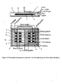
- the DDP pad shown in Figure 1 generally comprises two substantially coplanar coils referenced 2 and 3 which are magnetically associated with and sit on top of, a core 4.
- the core 4 consists of a plurality of individual lengths of permeable material such as ferrite strips or bars 5 which are arranged parallel to each other but spaced apart.
- the pad construction may include a spacer 6 on which the core is located, and a plate 7 below the spacer.
- a cover 8 may be provided on the other surface of the flat coils 2 and 3.
- Padding 9 may be provided about the periphery of the pad.
- the coils 2 and 3 each define a pole area 10 and 11 respectively.
- This DDP pad construction as shown in Figure 1 shows very good characteristics suitable for IPT power transfer applications such as vehicle charging.
- the coils 2, 3 may be connected out of phase and driven by a single inverter to produce a stationary time varying magnetic field to couple to a receiver (which may for example be of substantially the same magnetic design) at distances suitable for electric vehicle power transfer with good coupling.
- FIG. 2 the DDP construction of Figure 1 is shown but further including a quadrature coil 12 (referred to herein as a DDPQ pad).
- the quadrature coil extends the power transfer profile when there is lateral movement of the construction shown in Figure 2 with respect to a flux generator such as the DDP pad of Figure 1 when energised by an appropriate inverter.
- the quadrature coil allows power to be extracted from the "vertical" component of the magnetic field that the receiver pad intercepts while the other coils 2, 3 facilitate power extraction from the "horizontal" component of the flux intercepted. Therefore, the construction of Figure 2 is suited as a flux receiver.
- FIG. 3 another construction is shown which is referred to in this document as a bi-polar pad or, alternatively, as a BPP pad.
- the BPP pad has a similar construction to the DDP pad discussed with respect to Figures 1 and 2 above as it enables excellent coupling to secondary receivers at distances suitable for charging and powering of electric vehicles.
- the pad BPP consists, from bottom up, of an aluminium plate 7, a dielectric spacer 6, a core 4 comprising four rows of ferrite bars 5 (referred to herein as ferrites), two flat substantially coplanar, yet overlapping and ideally "rectangular" shaped coils 2, 3 (although in practice these are more oval due to the ease in winding Litz wire) spread out in the lateral direction, and a dielectric cover 8.
- the core 4 acts as a shield so that ideally all flux is directed away form the core 4 through the top of the pad.
- the plate 7 merely acts to a) eliminate and small stray or spurious fields that may be presnt beneath the core 4 in certain environments, and b) provide additional structural strength.
- Table A1 defines the actual dimensions investigated in simulation and for one experimental prototype.
- the magnetic structure of the BPP is designed so that there is substantially no mutual coupling between either of the coils 2, 3 in the primary, as described later. This allows the coils to be driven independently at any magnitude or phase without coupling voltage into each other which if present would oppose the power output of such a coil.
- the two coils within the BPP can be driven using two separate but synchronised inverters operating with known current magnitude and phase difference. If the coils are completely magnetically decoupled ideally there will be no power transfer between the primary inverters to limit power transfer to the secondary receiver.
- the two inverters are synchronised but operated so as to produce currents with the same RMS magnitude, but operating 90 degrees out of phase in each of the coils 2, 3.
- a spatially varying and time varying magnetic field is created rather than the stationary time varying magnetic field of the DDP.
- Figure 7 shows the left column represents a DDP pad and the right column represents a BPP pad. The spatial variation in the field of the BPP and appears as a sliding movement in alternate directions between the poles of the coils 2, 3.
- the field may be directed in response to the output of a sensor for example which may sense where greater field strength is required, or where the field strength should be reduced. Also, the field strength may be time varying but spatially stationary dependent on where across the pad the field is required.
- the power transfer profile of a BPP with a sliding time varying magnetic field is evaluated against the power transfer profile of a DDP magnetic structure driven from a single phase primary supply at identical current and frequency (the dimensions of which are defined in Tables A2.). Both systems are evaluated under identical conditions being coupled to an identical DDQP receiver (i.e. a DDP pad including a quadrative coil such as that of Figure 2 used as a flux receiver) at identical height and offsets (the dimensions of which are defined in Table A3).
- an identical DDQP receiver i.e. a DDP pad including a quadrative coil such as that of Figure 2 used as a flux receiver
- the BPP creates what may be termed a sliding time varying magnetic field it is desirable to determine the preferred length of the four ferrite strips 5 used in its base above which the coils 2, 3 are placed.
- these ferrite strips 5 are used to enhance the power transfer and ensure that a predominately single sided flux field is created to best couple to the secondary power receiver, while ensuring that a minimal amount of ferrite is used to keep weight to a minimum and restrict the inductance of the pad.
- the ferrite strips should preferably extend under the winding coils otherwise the field may not be forced upwards towards the receiver.
- the ferrite strips 5 were constructed using readily available slabs that are each a standard length of 93 mm. Each strip was conveniently chosen to be multiples of this length. Configurations with six (558 mm), eight (744 mm) and ten (930 mm) slabs lumped together were investigated. In all designs (apart from the 10 slab ferrite configuration) the external dimensions of the pad size of the BPP are identical to the DDP enabling a fair comparison. The ten piece ferrite configuration however forces the overall length (in the x direction) of the transmitter (or generator) pad to be increased beyond the standard length by 200 mm (compared to all other pads including the DDP configurations compared) and therefore is only included in evaluations to consider the impact of extensions to the ferrite beyond the coil dimensions. As indicated in Table A1 the distance between the ends of the two coils in all three BPP setups is identical although the overlap between the coils is set to that required to avoid mutual coupling arising between the primary coils.
- the ideal configuration can be set.
- the optimal overlap is dependent on the length of the ferrite strips underneath the coils.
- the overlapping ratio, r 0 was found to be 0.53, 0.34 and 0.25 respectively.
- the finite element solver JMAG Studio TM version 10.0 was used to simulate all proposed magnetic structures. Validation of the simulator outputs was confirmed by constructing a prototype BPP in the laboratory using ferrite strips comprised of 6 ferrite slabs in the base and compared against simulations. This scaled model used the external dimensions of table A1 for the BPP but simplified coils with only 10 turns each to simplify the construction.
- the receiver was a DDQP as described in table A3. The comparison between measurement and simulation of Figure 5 shows excellent correlation.
- the power profiles given here are the total uncompensated VA power output which is determined using separate measurements of the receiver open circuit voltage ( V oc ) and short circuit current ( I sc ).
- the DDQP reciever has two sets of coils, the coils 2, 3 (assuming they are in series) and the quadrature (Q) coil 12. In this case the uncompensated power is found for both sets of coils separately and the total uncompensated power available from the pickup is referred to as the total power which is simply calculated as the sum of the power from the two sets of coils. It is this total power which underlies the power transfer profile.
- each BPP design can therefore be confidently determined using 3D simulation and is shown in Figure 6 .
- the BPP is excited with a 20kHz current with 23A rms while the receiver is the DDQP.
- the parameters governing their relative position are referred to as the offset distances, in Cartesian coordinates, that is: x os (lateral), y os (longitudinal) and z os (vertical).
- the configuration of the two pads lying on top of each other with their dielectric covers 8 touching is (0,0,0).
- the vertical offset z os is 200 mm.
- the flux density appears qualitatively different, especially around the right edge where the flux density is high for the eight and ten ferrite setups, but not for the six ferrite setup.
- the flux is even better confined, with less of the field "wrapping around" the side of the track pad, again a factor responsible for decreasing the power transfer, since the field will not be pushed towards the pickup (i.e. the receiver pad) as desired.
- the BPP with the eight ferrite slabs in each ferrite base strip (BPP8) is compared to the DDP in Figure 9 .
- the power transfer profile of the BPP8 compared against the profile of the DDP reveals the very evident differences in shape and maximum.
- the BPP8 yields around 70% of the DDP's maximum power and has similar power profile shapes.
- the power levels shown and coupling achieved is however sufficient to deliver suitable levels of power to an electric vehicle for example, at distances required for practical application and furthermore do not exhibit as significant a rate of change of variation of power around the peak with offset as that seen in the DDP power profile. This limited rate of charge of power is an advantage when considering power highway applications given there will not be severe fluctuations in power with lateral movement.
- Table A1 Dimensions of the BPP Common Dimensions Winding width 80 mm Ferrite spacing 32 mm Ferrite width 28 mm Y coil spacing 50 mm Y padding 46 mm Cover thickness 6 mm Coil height 4 mm Ferrite height 16 mm Spacer thickness 6 mm Plate thickness 4 mm Variations based on number of ferrites
- BBP6 using 6 ferrite slabs to make each ferrite strip (BPP6) Ferrite length 558 mm (BBP6) Overlap 156 mm X coil spacing 10 mm X padding 10 mm
- C BBP10: using 10 ferrite slabs to make each ferrite strip Ferrite length 930 mm
- Overlap 39 mm X coil spacing -174 mm (- represents an overlap) X padding 110 mm (nb: 200mm added
Description
- This invention relates to apparatus for generating or receiving magnetic flux. The invention has particular, but not sole, application to a low profile, substantially flat device such as a pad for power transfer using an inductive power transfer (IPT) system.
- IPT systems, and the use of a pad which includes one or more windings which may comprise the primary or secondary windings for inductive power transfer, are reproduced in our published international patent application
WO 2008/14033 - One particular application of IPT power transfer pads is electric vehicle charging, and that application is discussed in this section to provide the background to one application of the invention. However, electric vehicle charging is an example of only one application, and the invention has application to inductive power transfer in general. Electric vehicle charging may occur while the vehicle is stationary, or alternatively while the vehicle is moving along a roadway, for example. IPT power transfer pads can be used both in the vehicle as a power "pickup" (i.e. the secondary side winding of the IPT system), and at a stationary location such as a garage floor or a roadway for example as the "charging pad" (i.e. the primary side winding) from which power is sourced.
- The purpose of an IPT roadway system is to wirelessly transfer power to a stationary or moving vehicle without physical contact to the vehicle. The transmitting part of the system consists of a power supply supplying a lumped coil (for example a pad as described above) or a track, with many similar lumped coils where such a system is tuned for operation at a suitable frequency, usually anywhere from 10 kHz to 150 kHz. Where the receiver is placed underneath a vehicle and coupled to receive power either when the vehicle is stationary above or near (in sufficiently close proximity to couple power) to the primary transmitter. The pickup receiver also typically comprises a lumped coil (such as a pad described above) which is connected to a converter and appropriate controller within the vehicle to regulate power. For convenience, the part of a roadway from which power may be received inductively is referred to herein as a track.
- The track may be formed by placing a plurality of pads along the centre of a lane in a roadway. This results in the possibility of an essentially continuous supply of power to the vehicle as it moves along the roadway in the immediate vicinity of the track.
- In recent years such systems have received increasing attention due to their potential to allow sustainable wireless powered personal transportation. For such a system to be useful it must not only be able to transfer sufficient power over an airgap of reasonable size (e.g. 100-300mm) it must also prove tolerant to any displacements between track and pickup, to avoid dependency on a vehicle-to-track guidance system. In a roadway system such displacement will most likely occur in the lateral direction (orthogonal to both vertical and the direction of movement) for moving vehicles. For stationary vehicle charging the ability to transfer acceptable levels of power with suitable longitudinal displacement is of particular concern in order to ensure ease of parking. The power transfer profile in the pick-up pad is ideally a smooth power profile which is essentially constant (and sufficient) over as wide as possible a distance laterally, with smooth drop-offs at each end. Such a power transfer profile eases the demands on the electronic (primary and secondary) regulators in the system, enabling improved operating performance for a comparable coupling over a system where during operation significant variations are experienced in the coupling between the primary and receiver pads.
-
JP2009 164293 -
WO2007/031897 relates to a device for recharging batteries, the device having a circuit, which comprises at least a first coil in a first layer and at least a second coil in a second layer. The coils have magnetic fields in opposite directions. The magnetic fields in opposite directions cancel each other out in the remote range. Hence, an unintentional effect on biological and electromechanical systems is avoided. -
US2005/140482 is directed to a system and method for transferring power without requiring direct electrical conductive contacts. There is provided a primary unit having a power supply and a substantially laminar charging surface having at least one conductor that generates an electromagnetic field when a current flows therethrough and having an charging area defined within a perimeter of the surface, the at least one conductor being arranged such that electromagnetic field lines generated by the at least one conductor are substantially parallel to the plane of the surface or at least subtend an angle of 45° or less to the surface within the charging area; and at least one secondary device including at least one conductor that may be wound about a core. - Because the electromagnetic field is spread over the charging area and is generally parallel or near-parallel thereto, coupling with flat secondary devices such as mobile telephones and the like is significantly improved in various orientations thereof.
- It is an object of the present invention to provide apparatus for generating and/or receiving magnetic flux for the purposes of inductive power transfer, or to at least provide the public or the industry with a useful choice.
- An invention is out in claim 1, dependent claims 2 to 13 define preferred embodiments of the invention.
- Preferably the flux pad is adapted to receive currents from a power supply which are out of phase with each other to produce a time varying magnetic field which also varies spatially. Preferably the field produced by the out-of-phase currents in the coils produces a time varying magnetic field which moves spatially and ultimately between the poles.
- Preferably the magnetic flux pad produces a sliding time varying magnetic field.
- Further aspects of the invention will become apparent from the following description.
- One or more embodiments of the invention will be described with reference to the accompanying drawings in which:
- Figure 1
- is a side view and a plan view respectively of a magnetic flux pad;
- Figure 2:
- is a side view and plan view respectively of the pad of
Figure 1 including a quadrature coil; - Figure 3:
- is a side view and plan view respectively of an alternative form of magnetic flux pad;
- Figure 4:
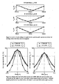
- is a series of graphs of open circuit voltage coupled in one coil of the pad of the preceding figure as a function of overlap with the other coil when that other coil is energised;
- Figure 5:
- shows graphs of uncompensated power against offset for a vertical space of 150 mm and 250 mm respectively;
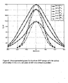
- Figure 6:
- is a graph of uncompensated power for three different flux pad constructions (according to
Figure 3 ) with the receiver pad offset either in the x or y direction at a vertical separation of 200 mm; - Figure 7:
- illustrates field plots for the pad construction of
Figure 3 andFigure 1 respectively at various instances of time over a full cycle of primary resonant current; - Figure 8:
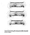
- shows the field plot of the pad construction of
Figure 3 with an increasing amount of ferrite in the core (from the top to the bottom direction); - Figure 9:
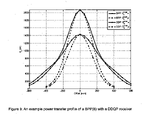
- shows a graph of an example of a power transfer profile of a pad construction according to that shown in
Figure 3 with a receiver pad that accords with that shown in the example ofFigure 2 . - Referring to
Figure 1 , a magnetic flux pad construction is shown. For convenience, this general construction is referred to herein as a DDP pad, and is generally referenced DDP in the relevant drawing figures. - The DDP pad shown in
Figure 1 generally comprises two substantially coplanar coils referenced 2 and 3 which are magnetically associated with and sit on top of, a core 4. As can be seen from the drawing figure, the core 4 consists of a plurality of individual lengths of permeable material such as ferrite strips or bars 5 which are arranged parallel to each other but spaced apart. The pad construction may include a spacer 6 on which the core is located, and a plate 7 below the spacer. In some embodiments a cover 8 may be provided on the other surface of the flat coils 2 and 3. Padding 9 may be provided about the periphery of the pad. As can be seen, the coils 2 and 3 each define a pole area 10 and 11 respectively. This DDP pad construction as shown inFigure 1 shows very good characteristics suitable for IPT power transfer applications such as vehicle charging. The coils 2, 3 may be connected out of phase and driven by a single inverter to produce a stationary time varying magnetic field to couple to a receiver (which may for example be of substantially the same magnetic design) at distances suitable for electric vehicle power transfer with good coupling. - Turning now to
Figure 2 , the DDP construction ofFigure 1 is shown but further including a quadrature coil 12 (referred to herein as a DDPQ pad). The quadrature coil extends the power transfer profile when there is lateral movement of the construction shown inFigure 2 with respect to a flux generator such as the DDP pad ofFigure 1 when energised by an appropriate inverter. The quadrature coil allows power to be extracted from the "vertical" component of the magnetic field that the receiver pad intercepts while the other coils 2, 3 facilitate power extraction from the "horizontal" component of the flux intercepted. Therefore, the construction ofFigure 2 is suited as a flux receiver. - Turning now to
Figure 3 , another construction is shown which is referred to in this document as a bi-polar pad or, alternatively, as a BPP pad. The BPP pad has a similar construction to the DDP pad discussed with respect toFigures 1 and2 above as it enables excellent coupling to secondary receivers at distances suitable for charging and powering of electric vehicles. - The pad BPP consists, from bottom up, of an aluminium plate 7, a dielectric spacer 6, a core 4 comprising four rows of ferrite bars 5 (referred to herein as ferrites), two flat substantially coplanar, yet overlapping and ideally "rectangular" shaped coils 2, 3 (although in practice these are more oval due to the ease in winding Litz wire) spread out in the lateral direction, and a dielectric cover 8. The core 4 acts as a shield so that ideally all flux is directed away form the core 4 through the top of the pad. The plate 7 merely acts to a) eliminate and small stray or spurious fields that may be presnt beneath the core 4 in certain environments, and b) provide additional structural strength. The BPP is shown in
Figure 3 , and Table A1 defines the actual dimensions investigated in simulation and for one experimental prototype. - The magnetic structure of the BPP is designed so that there is substantially no mutual coupling between either of the coils 2, 3 in the primary, as described later. This allows the coils to be driven independently at any magnitude or phase without coupling voltage into each other which if present would oppose the power output of such a coil.
- In one mode of operation, the two coils within the BPP can be driven using two separate but synchronised inverters operating with known current magnitude and phase difference. If the coils are completely magnetically decoupled ideally there will be no power transfer between the primary inverters to limit power transfer to the secondary receiver.
- In one embodiment the two inverters are synchronised but operated so as to produce currents with the same RMS magnitude, but operating 90 degrees out of phase in each of the coils 2, 3. (In a stationary application this would likely be two H bridge inverters with LCL structures tuned to resonance at the desired operating frequency the last L in each case being partially constructed using the pad inductance, where the primary inverters preferably have a common DC bus to simplify the input electronics from the mains. By having a 90° phase separation between the currents in the coils 2, 3, a spatially varying and time varying magnetic field is created rather than the stationary time varying magnetic field of the DDP. This is shown in
Figure 7 in which the left column represents a DDP pad and the right column represents a BPP pad. The spatial variation in the field of the BPP and appears as a sliding movement in alternate directions between the poles of the coils 2, 3. - It should be noted that other relative phase and/or magnitude variations between the currents in the coils could be used to shape the field if there is a need to reduce the field emissions on one side of the transmitter to avoid leakage during operation due to offset nature of the coupled receiver, for example to meet ICNIRP regulations. Thus the field may be directed in response to the output of a sensor for example which may sense where greater field strength is required, or where the field strength should be reduced. Also, the field strength may be time varying but spatially stationary dependent on where across the pad the field is required.
- In a further embodiment it is also possible to operate the coils 2, 3 180 degrees out of phase so that they can be simply connected to one inverter (as in the DDP operation). This particular single phase operating mode is a second possible mode of operation to simplify the electronic control and power conversion that will produce a stationary time varying field as for the DDP.
- As a means of comparison, the power transfer profile of a BPP with a sliding time varying magnetic field is evaluated against the power transfer profile of a DDP magnetic structure driven from a single phase primary supply at identical current and frequency (the dimensions of which are defined in Tables A2.). Both systems are evaluated under identical conditions being coupled to an identical DDQP receiver (i.e. a DDP pad including a quadrative coil such as that of
Figure 2 used as a flux receiver) at identical height and offsets (the dimensions of which are defined in Table A3). - Given the BPP creates what may be termed a sliding time varying magnetic field it is desirable to determine the preferred length of the four ferrite strips 5 used in its base above which the coils 2, 3 are placed. As in the known DDP these ferrite strips 5 are used to enhance the power transfer and ensure that a predominately single sided flux field is created to best couple to the secondary power receiver, while ensuring that a minimal amount of ferrite is used to keep weight to a minimum and restrict the inductance of the pad. In such a sliding field it is shown that the ferrite strips should preferably extend under the winding coils otherwise the field may not be forced upwards towards the receiver.
- In this evaluation the ferrite strips 5 were constructed using readily available slabs that are each a standard length of 93 mm. Each strip was conveniently chosen to be multiples of this length. Configurations with six (558 mm), eight (744 mm) and ten (930 mm) slabs lumped together were investigated. In all designs (apart from the 10 slab ferrite configuration) the external dimensions of the pad size of the BPP are identical to the DDP enabling a fair comparison. The ten piece ferrite configuration however forces the overall length (in the x direction) of the transmitter (or generator) pad to be increased beyond the standard length by 200 mm (compared to all other pads including the DDP configurations compared) and therefore is only included in evaluations to consider the impact of extensions to the ferrite beyond the coil dimensions. As indicated in Table A1 the distance between the ends of the two coils in all three BPP setups is identical although the overlap between the coils is set to that required to avoid mutual coupling arising between the primary coils.
- When the two primary coils 2, 3 of the BPP are placed with an arbitrary overlap with respect to each other, there will be a mutual coupling between the coils. However for a certain ratio of overlap to coil width, denoted r o, this mutual coupling is almost zero. The ideal overlap required to ensure no mutual coupling exists between each primary coil is not simple due the presence of the ferrite but can be determined by simply fixing one coil and energising this with a predetermined current at fixed frequency (either via a suitable 3D simulator or using a suitable experimental setup, for example). The open circuit voltage induced in the second primary coil can then be measured. If the second coil is moved so as to change the overlap there will be a change in coupled voltage. When this is minimised (ideally zero) the ideal configuration can be set. As shown in
Figure 4 , the optimal overlap is dependent on the length of the ferrite strips underneath the coils. For the six, eight and ten piece ferrite pad the overlapping ratio, r 0 was found to be 0.53, 0.34 and 0.25 respectively. - The finite element solver JMAG Studio™ version 10.0 was used to simulate all proposed magnetic structures. Validation of the simulator outputs was confirmed by constructing a prototype BPP in the laboratory using ferrite strips comprised of 6 ferrite slabs in the base and compared against simulations. This scaled model used the external dimensions of table A1 for the BPP but simplified coils with only 10 turns each to simplify the construction. The receiver was a DDQP as described in table A3. The comparison between measurement and simulation of
Figure 5 shows excellent correlation. - The power profiles given here are the total uncompensated VA power output which is determined using separate measurements of the receiver open circuit voltage (Voc ) and short circuit current (Isc ). The uncompensated VA is a well known measure of the power performance of a pad given by Su =Voc *lsc. The DDQP reciever has two sets of coils, the coils 2, 3 (assuming they are in series) and the quadrature (Q) coil 12. In this case the uncompensated power is found for both sets of coils separately and the total uncompensated power available from the pickup is referred to as the total power which is simply calculated as the sum of the power from the two sets of coils. It is this total power which underlies the power transfer profile.
- The power transfer profile of each BPP design can therefore be confidently determined using 3D simulation and is shown in
Figure 6 . Here the BPP is excited with a 20kHz current with 23A rms while the receiver is the DDQP. The parameters governing their relative position are referred to as the offset distances, in Cartesian coordinates, that is: x os (lateral), y os (longitudinal) and z os (vertical). The configuration of the two pads lying on top of each other with their dielectric covers 8 touching is (0,0,0). The vertical offset z os is 200 mm. - Notably there is a significant increase in power when the ferrite under the coils is extended, and it is clear that the ferrite should extend at least under the entire coil 2, 3 (BPP with 8 ferrite slabs). The reason for the drastic increase in uncompensated power from the BPP as ferrite is added to its base, lies in the non-stationary nature of its magnetic field. The field close to the BPP pad can best be described as a sliding wave across the surface, unlike the DDP which pulsates up and down due to its single phase nature. This sliding nature, and fundamental difference, between the BPP and the single phased DDP, is clearly evident in
Figure 7 , where the magnetic flux density is compared phase by phase for half a period. InFigure 7 field plots of both the BPP8 and DDP coupling to a DDQP receiver are shown, at various instances in time over a full cycle of the primary resonant current. From top to bottom shows 0, 30, 60, 90, 120 and 150 degrees (where in the bipolar the other phase is operated with 90 degree separation). The plots in the left column are for a BPP pad with 8 ferrite slabs. The plots in the right column are for a DDP pad. The flux from the single phase DDP pad pulsates up and down, having a very strong and confined flux centred over the pad, whereas the BPP has a more constant flux pattern-wise, but this pattern shifts over the surface of the pad like a sliding wave as the phase advances. - The sliding wave of the BPP gives rise to very localised high flux on the edge of pad, whereas the DDP pad keeps the strong flux in the centre of the pad. In the six piece version there is no ferrite under the ends of the coils, and the flux is not contained well enough by the dielectric filling material 6 (wood). It is therefore not radiated upwards, but rather inducing eddy currents in the aluminium base plate 7 of the pad. In
Figure 8 the three setups are compared for the same phase.Figure 8 shows field plots for a BPP pad with six (top), eight (middle) and ten (bottom) slabs making up each ferrite strip in the base, in the presence of a vertical offset DDQP receiver at 0 degrees. The flux density appears qualitatively different, especially around the right edge where the flux density is high for the eight and ten ferrite setups, but not for the six ferrite setup. In the ten ferrite version, the flux is even better confined, with less of the field "wrapping around" the side of the track pad, again a factor responsible for decreasing the power transfer, since the field will not be pushed towards the pickup (i.e. the receiver pad) as desired. - The BPP with the eight ferrite slabs in each ferrite base strip (BPP8) is compared to the DDP in
Figure 9 . The power transfer profile of the BPP8 compared against the profile of the DDP reveals the very evident differences in shape and maximum. As configured, the BPP8 yields around 70% of the DDP's maximum power and has similar power profile shapes. The power levels shown and coupling achieved is however sufficient to deliver suitable levels of power to an electric vehicle for example, at distances required for practical application and furthermore do not exhibit as significant a rate of change of variation of power around the peak with offset as that seen in the DDP power profile. This limited rate of charge of power is an advantage when considering power highway applications given there will not be severe fluctuations in power with lateral movement.Table A1: Dimensions of the BPP Common Dimensions Winding width 80 mm Ferrite spacing 32 mm Ferrite width 28 mm Y coil spacing 50 mm Y padding 46 mm Cover thickness 6 mm Coil height 4 mm Ferrite height 16 mm Spacer thickness 6 mm Plate thickness 4 mm Variations based on number of ferrites A: BBP6: using 6 ferrite slabs to make each ferrite strip (BPP6) Ferrite length 558 mm (BBP6) Overlap 156 mm X coil spacing 10 mm X padding 10 mm B: BBP8: using 8 ferrite slabs to make each ferrite strip Ferrite length 774 mm Overlap 74 mm X coil spacing - 83 mm (- represents an overlap) X padding 10 mm C: BBP10: using 10 ferrite slabs to make each ferrite strip Ferrite length 930 mm Overlap 39 mm X coil spacing -174 mm (- represents an overlap) X padding 110 mm (nb: 200mm added overall to padding to fit extra ferrites) Table A2: Dimensions of the DDP Winding width 80 mm Inner winding width 120mm Ferrite spacing 32 mm Ferrite width 28 mm Y coil spacing 10 mm Y padding 46 mm Cover thickness 6 mm Coil height 4 mm Ferrite height 16 mm Spacer thickness 6 mm Plate thickness 4 mm Ferrite length 558 mm X coil spacing 10 mm X padding 10 mm Table A3: Dimensions of the DDQP Winding width 80 mm Inner winding width 120mm Ferrite spacing 32 mm Ferrite width 28 mm Y coil spacing 10 mm Y padding 46 mm Cover thickness 6 mm Coil height 4 mm Ferrite height 16 mm Spacer thickness 6 mm Plate thickness 4 mm Ferrite length 558 mm X coil spacing 10 mm X padding 10 mm Quadrature coil length 534 mm - Although this invention has been described by way of example and with reference to possible embodiments thereof, it is to be understood that modifications or improvements may be made thereto without departing from the scope the claims
Claims (13)
- A magnetic flux pad for generating or receiving magnetic flux, the pad comprising a magnetically permeable core (4), two flat partially overlapping coils (2, 3) magnetically associated with the core (4) whereby there is substantially no mutual coupling between the coils (2, 3),
wherein the magnetically permeable core (4) includes a plurality of individual lengths of permeable material (5) which are arranged parallel to, but spaced apart from, each other and which extend under the entire coils (2, 3). - A magnetic flux pad as claimed in claim 1 wherein an overlap between the coils (2, 3) is set such that the coils (2, 3) are completely magnetically decoupled.
- A magnetic flux pad as claimed in any one of the preceding claims wherein the coils (2, 3) are coplanar.
- A magnetic flux pad as claimed in any one of the preceding claims wherein the coils (2, 3) are provided on one side of the permeable core (4), and a shielding means is provided on the other side of the core (4).
- A magnetic flux pad as claimed in claim 4 wherein the shielding means comprises a shielding plate made of a material suitable to eliminate stray or spurious fields, such as aluminium.
- A magnetic flux pad as claimed in any one of the preceding claims wherein a dielectric cover is provided on the side of the coils (2, 3) opposite the magnetic core (4).
- Power supply apparatus for an inductive power transfer system, the power supply apparatus including:a magnetic flux pad for generating a magnetic flux according to any of claims 1 to 6; anda power supply adapted to provide a current in one coil which has a different phase to a current in the other coil.
- Power supply apparatus as claimed in claim 7 wherein the power supply is adapted to adjust the phase to produce a field that varies with time and with spatial position on the pad.
- Power supply apparatus as claimed in claim 7 or claim 8 including means to detect where a field is or is not required in the vicinity of the pad and adjust the relative phase and/or amplitude of the current in the coils (2, 3) in response to an output of a sensing means.
- Power supply apparatus as claimed in any one of claims 7 to 9 wherein the power supply includes an inverter for each coil.
- Power supply apparatus as claimed in any one of claims 7 to 10 wherein the power supply comprises two inverters which are synchronised with each other to produce a current in one coil which is 90° out of phase with the current in the other coil.
- Power supply apparatus as claimed in any one of claims 7 to 10 wherein the power supply operates the coils (2, 3) 180° out of phase with each other.
- Power supply apparatus as claimed in claim 12 wherein the power supply includes one inverter for energising both coils (2, 3).
Applications Claiming Priority (2)
| Application Number | Priority Date | Filing Date | Title |
|---|---|---|---|
| US27370109P | 2009-08-07 | 2009-08-07 | |
| PCT/NZ2010/000160 WO2011016737A1 (en) | 2009-08-07 | 2010-08-06 | Inductive power transfer system |
Publications (3)
| Publication Number | Publication Date |
|---|---|
| EP2462679A1 EP2462679A1 (en) | 2012-06-13 |
| EP2462679A4 EP2462679A4 (en) | 2017-07-12 |
| EP2462679B1 true EP2462679B1 (en) | 2022-09-28 |
Family
ID=43544512
Family Applications (2)
| Application Number | Title | Priority Date | Filing Date |
|---|---|---|---|
| EP10806691.1A Active EP2462679B1 (en) | 2009-08-07 | 2010-08-06 | Inductive power transfer system |
| EP10806690.3A Pending EP2462001A4 (en) | 2009-08-07 | 2010-08-06 | Roadway powered electric vehicle system |
Family Applications After (1)
| Application Number | Title | Priority Date | Filing Date |
|---|---|---|---|
| EP10806690.3A Pending EP2462001A4 (en) | 2009-08-07 | 2010-08-06 | Roadway powered electric vehicle system |
Country Status (7)
| Country | Link |
|---|---|
| US (3) | US10325717B2 (en) |
| EP (2) | EP2462679B1 (en) |
| JP (6) | JP2013502193A (en) |
| KR (3) | KR20120061085A (en) |
| CN (3) | CN102577011B (en) |
| IN (2) | IN2012DN01947A (en) |
| WO (2) | WO2011016737A1 (en) |
Families Citing this family (174)
| Publication number | Priority date | Publication date | Assignee | Title |
|---|---|---|---|---|
| US11522389B2 (en) * | 2008-09-11 | 2022-12-06 | Auckland Uniservices Limited | Inductively coupled AC power transfer |
| JP4909446B2 (en) * | 2009-05-14 | 2012-04-04 | トヨタ自動車株式会社 | Vehicle charging device |
| EP2462679B1 (en) | 2009-08-07 | 2022-09-28 | Auckland UniServices Limited | Inductive power transfer system |
| US20120313444A1 (en) * | 2009-10-12 | 2012-12-13 | John Talbot Boys | Inductively controlled series resonant ac power transfer |
| JP5941046B2 (en) * | 2010-08-06 | 2016-06-29 | オークランド ユニサービシズ リミテッドAuckland Uniservices Limited | Inductive power receiver device |
| NZ589865A (en) * | 2010-12-10 | 2013-06-28 | Auckland Uniservices Ltd | Inductive power transfer pick-up with separate AC and DC outputs |
| DE102010054848A1 (en) * | 2010-12-16 | 2012-06-21 | Conductix-Wampfler Ag | Device for inductive transmission of electrical energy |
| US20120169131A1 (en) * | 2010-12-29 | 2012-07-05 | Choudhary Vijay N | Phase shift power transfer |
| WO2012101729A1 (en) | 2011-01-26 | 2012-08-02 | パナソニック株式会社 | Non-contact charging module and non-contact charging instrument |
| DE102011004348A1 (en) * | 2011-02-17 | 2012-08-23 | Beckhoff Automation Gmbh | Method and position detection device for detecting a position of a movable element of a drive device |
| EP2694557A4 (en) | 2011-04-08 | 2015-07-15 | Auckland Uniservices Ltd | Local demand side power management for electric utility networks |
| US20120311363A1 (en) * | 2011-05-31 | 2012-12-06 | Nam Yun Kim | Wireless power transmission and charging system, and communication method of wireless power transmission and charging system |
| WO2012172813A1 (en) | 2011-06-14 | 2012-12-20 | パナソニック株式会社 | Communication device |
| DE102011078883A1 (en) * | 2011-07-08 | 2013-01-10 | Robert Bosch Gmbh | Inductive charging device and control method |
| WO2013019122A1 (en) * | 2011-07-08 | 2013-02-07 | Auckland Uniservices Limited | Interoperability of magnetic structures for inductive power transfer systems |
| WO2013019124A1 (en) * | 2011-07-19 | 2013-02-07 | Auckland Uniservices Limited | Double conductor single phase inductive power transfer tracks |
| KR101363950B1 (en) * | 2011-08-26 | 2014-02-20 | 한국과학기술원 | Pickup with Compensation Winding for Electric Vehicle |
| DE102011112610B4 (en) * | 2011-09-05 | 2020-06-04 | Grenzebach Maschinenbau Gmbh | Device and method for the wireless transmission of electrical energy to vehicles in the manner of "mobile petrol pumps", as well as a computer program and machine-readable carrier |
| US10263466B2 (en) | 2011-09-07 | 2019-04-16 | Auckland Uniservices Limited | Magnetic field shaping for inductive power transfer |
| KR101305833B1 (en) | 2011-09-09 | 2013-09-06 | 엘지이노텍 주식회사 | A wireless power realy apparatus and transmission system |
| KR102064473B1 (en) | 2011-10-28 | 2020-01-09 | 오클랜드 유니서비시즈 리미티드 | Non-ferrite structures for inductive power transfer |
| CN103918192A (en) | 2011-11-02 | 2014-07-09 | 松下电器产业株式会社 | Non-contact wireless communication coil, transmission coil, and portable wireless terminal |
| US10204734B2 (en) | 2011-11-02 | 2019-02-12 | Panasonic Corporation | Electronic device including non-contact charging module and near field communication antenna |
| DE102011119259A1 (en) | 2011-11-24 | 2013-05-29 | Bombardier Transportation Gmbh | Doppler rectifier for multiphase contactless power transmission system |
| CN104011962B (en) * | 2011-12-22 | 2017-02-22 | 皇家飞利浦有限公司 | Charging coil system for a drop-in target device such as a toothbrush |
| DE102012000408A1 (en) * | 2012-01-12 | 2013-07-18 | Phoenix Contact Gmbh & Co. Kg | Resonant inductive power supply device |
| DE102012000409A1 (en) | 2012-01-12 | 2013-07-18 | Phoenix Contact Gmbh & Co. Kg | Modular data system with inductive energy transfer |
| US11277027B2 (en) * | 2012-02-02 | 2022-03-15 | Auckland Uniservices Limited | VAR control for inductive power transfer systems |
| KR20140129172A (en) * | 2012-02-16 | 2014-11-06 | 오클랜드 유니서비시즈 리미티드 | Multiple coil flux pad |
| JP2013169122A (en) | 2012-02-17 | 2013-08-29 | Panasonic Corp | Non-contact charge module and portable terminal having the same |
| ES2662449T3 (en) | 2012-02-22 | 2018-04-06 | Toyota Jidosha Kabushiki Kaisha | Contactless electric power transfer device, contactless electric power receiving device, and contactless electric power receiving system |
| CN102611205B (en) * | 2012-03-08 | 2014-12-10 | 重庆大学 | Efficient dynamic-sensing power supply system for electric vehicle |
| US9899145B2 (en) | 2012-03-20 | 2018-02-20 | Auckland Uniservices Ltd. | Winding arrangements in wireless power transfer systems |
| GB2502084A (en) * | 2012-05-14 | 2013-11-20 | Bombardier Transp Gmbh | Arrangement for providing vehicles with energy comprising magnetisable material |
| JP6024195B2 (en) * | 2012-05-15 | 2016-11-09 | スミダコーポレーション株式会社 | Contactless power supply system and power transmission coil for contactless power supply system |
| EP2854145B1 (en) * | 2012-05-21 | 2018-03-28 | Technova Inc. | Contactless electrical-power-supplying transformer for moving body |
| DE102012209898A1 (en) * | 2012-06-13 | 2013-12-19 | Siemens Aktiengesellschaft | Arrangement for inductive wireless delivery of energy |
| GB2503484A (en) * | 2012-06-27 | 2014-01-01 | Bombardier Transp Gmbh | Inductive vehicle charging station and method with lateral electromagnetic shielding |
| JP6112383B2 (en) | 2012-06-28 | 2017-04-12 | パナソニックIpマネジメント株式会社 | Mobile device |
| JP6008237B2 (en) | 2012-06-28 | 2016-10-19 | パナソニックIpマネジメント株式会社 | Mobile device |
| EP2870675A4 (en) * | 2012-07-09 | 2016-04-27 | Auckland Uniservices Ltd | Flux coupling device and magnetic structures therefor |
| KR20220150404A (en) | 2012-08-28 | 2022-11-10 | 오클랜드 유니서비시즈 리미티드 | A polyphase inductive power transfer system with individual control of phases |
| CN105164887B (en) | 2012-08-31 | 2018-12-21 | 奥克兰联合服务有限公司 | Improve the efficiency of non-self-tuning radio energy transmission system |
| EP2893605B1 (en) | 2012-09-06 | 2019-04-24 | Auckland UniServices Limited | Local demand side power management for electric utility networks |
| US9472338B2 (en) | 2012-09-11 | 2016-10-18 | Qualcomm Incorporated | Wireless power transfer system coil arrangements and method of operation |
| KR101976063B1 (en) | 2012-10-05 | 2019-05-09 | 삼성디스플레이 주식회사 | Apparatus and method for sensing bending of a flexible display using mutual inductance |
| US10014104B2 (en) * | 2012-11-02 | 2018-07-03 | Qualcomm Incorporated | Coil arrangements in wireless power transfer systems for low electromagnetic emissions |
| KR102225531B1 (en) | 2012-11-09 | 2021-03-08 | 캘리포니아 인스티튜트 오브 테크놀로지 | Smart rf lensing: efficient, dynamic and mobile wireless power transfer |
| US11843260B2 (en) | 2012-11-09 | 2023-12-12 | California Institute Of Technology | Generator unit for wireless power transfer |
| US10090714B2 (en) | 2013-11-12 | 2018-10-02 | California Institute Of Technology | Wireless power transfer |
| US11616520B2 (en) | 2012-11-09 | 2023-03-28 | California Institute Of Technology | RF receiver |
| CN109017346B (en) * | 2012-11-12 | 2022-01-25 | 奥克兰联合服务有限公司 | Vehicle or moving object detection |
| DE102012023363B4 (en) * | 2012-11-29 | 2014-06-26 | Audi Ag | Subframe for a motor vehicle |
| US20140159673A1 (en) * | 2012-12-07 | 2014-06-12 | Samsung Electronics Co., Ltd. | Wireless charging apparatus and method |
| KR20140076993A (en) * | 2012-12-13 | 2014-06-23 | 엘지이노텍 주식회사 | Wireless power device |
| JP5286445B1 (en) * | 2012-12-28 | 2013-09-11 | 株式会社日立パワーソリューションズ | Wireless power feeder for electric mobile body |
| US9142990B2 (en) | 2013-01-18 | 2015-09-22 | Qualcomm Incorporated | Method of multi-coil operation and optimization |
| JP6164853B2 (en) * | 2013-01-28 | 2017-07-19 | 株式会社テクノバ | Non-contact power supply system while traveling |
| KR102227449B1 (en) | 2013-03-27 | 2021-03-15 | 오클랜드 유니서비시즈 리미티드 | Electromagnetic field confinement |
| GB2512855A (en) | 2013-04-09 | 2014-10-15 | Bombardier Transp Gmbh | Receiving device for receiving a magnetic field and for producing electric energy by magnetic induction |
| GB2512862A (en) | 2013-04-09 | 2014-10-15 | Bombardier Transp Gmbh | Receiving device with coil of electric line for receiving a magnetic field and for producing electric energy by magnetic induction |
| US9520748B2 (en) * | 2013-04-17 | 2016-12-13 | El Wha Llc | Systems and methods for providing wireless power to a power-receiving device, and related power-receiving devices |
| ES2761337T3 (en) * | 2013-04-26 | 2020-05-19 | Use System Eng Holding B V | Power transfer system |
| US9676285B2 (en) | 2013-05-01 | 2017-06-13 | Qualcomm Incorporated | Vehicle charging pad having reduced thickness |
| DE102013007971A1 (en) * | 2013-05-10 | 2014-11-27 | Audi Ag | Method for operating a charging device for single and multi-phase charging of an energy storage device of a motor vehicle and charging device |
| US9446674B2 (en) * | 2013-07-15 | 2016-09-20 | Qualcomm Incorporated | Systems, methods, and apparatus related to mutual detection and identification of electric vehicle and charging station |
| KR102125917B1 (en) * | 2013-08-07 | 2020-07-08 | 엘지이노텍 주식회사 | Wireless power transmitting device |
| US9438064B2 (en) * | 2013-08-30 | 2016-09-06 | Qualcomm Incorporated | System and method for alignment and compatibility detection for a wireless power transfer system |
| US10186912B2 (en) | 2013-09-13 | 2019-01-22 | Qualcomm Incorporated | Pickup coil design for tight spaces and asymmetrical coupling |
| DE102013219536A1 (en) * | 2013-09-27 | 2015-04-02 | Siemens Aktiengesellschaft | Charging station for wireless energy-related coupling of an electrically driven vehicle |
| WO2015072863A1 (en) | 2013-11-13 | 2015-05-21 | Powerbyproxi Limited | Transmitter for inductive power transfer systems |
| KR102473074B1 (en) * | 2013-11-22 | 2022-11-30 | 캘리포니아 인스티튜트 오브 테크놀로지 | Generator unit for wireless power transfer |
| JP6156115B2 (en) | 2013-12-13 | 2017-07-05 | トヨタ自動車株式会社 | Power transmission equipment |
| US9837204B2 (en) | 2013-12-17 | 2017-12-05 | Qualcomm Incorporated | Coil topologies for inductive power transfer |
| GB2521676B (en) * | 2013-12-31 | 2016-08-03 | Electric Road Ltd | System and method for powering an electric vehicle on a road |
| JP6226500B2 (en) * | 2014-01-21 | 2017-11-08 | 株式会社テクノバ | Contactless power supply system |
| US9815379B2 (en) * | 2014-01-21 | 2017-11-14 | Qualcomm Incorporated | Systems and methods for electric vehicle induction coil alignment |
| KR102363633B1 (en) | 2014-02-20 | 2022-02-17 | 삼성전자주식회사 | Method for controlling wireless power transmitter and wireless power transmitter |
| WO2015126103A1 (en) * | 2014-02-20 | 2015-08-27 | 삼성전자주식회사 | Wireless power transmitter and method for controlling wireless power transmitter |
| JP2015159693A (en) * | 2014-02-25 | 2015-09-03 | 株式会社豊田自動織機 | Non-contact power transmission system and power reception device |
| EP3128643A4 (en) * | 2014-03-04 | 2018-01-10 | Technova Inc. | System for wirelessly supplying power during moving |
| US9772401B2 (en) | 2014-03-17 | 2017-09-26 | Qualcomm Incorporated | Systems, methods, and apparatus for radar-based detection of objects in a predetermined space |
| JP6303684B2 (en) * | 2014-03-25 | 2018-04-04 | Tdk株式会社 | Coil unit and wireless power transmission device |
| JP6299320B2 (en) * | 2014-03-25 | 2018-03-28 | Tdk株式会社 | Coil unit and wireless power transmission device |
| US10083792B2 (en) * | 2014-05-14 | 2018-09-25 | Qualcomm Incorporated | System, method and apparatus for reducing the height of bipolar transmitters and/or receivers in electric vehicle charging |
| EP3146541B1 (en) | 2014-05-19 | 2020-06-03 | Apple Inc. | Magnetically permeable core and an inductive power transfer coil arrangement |
| WO2015178780A1 (en) | 2014-05-19 | 2015-11-26 | Powerbyproxi Limited | Magnetically permeable core and inductive power transfer coil arrangement |
| US9463705B2 (en) * | 2014-06-10 | 2016-10-11 | Qualcomm Incorporated | System and method for adaptive charging compliance control |
| JP6630716B2 (en) | 2014-07-08 | 2020-01-15 | オークランド ユニサービシズ リミテッドAuckland Uniservices Limited | Inductive power transmission device |
| WO2016007024A1 (en) | 2014-07-09 | 2016-01-14 | Auckland Uniservices Limited | Inductive power system suitable for electric vehicles |
| CN112510856A (en) | 2014-08-12 | 2021-03-16 | 苹果公司 | System and method for power transmission |
| US9819208B2 (en) * | 2014-08-29 | 2017-11-14 | General Electronics Applications, Inc. | Battery management circuit having cell connections for batteries and a plurality of corresponding windings and diodes |
| US9680312B2 (en) * | 2014-09-10 | 2017-06-13 | Qualcomm Incorporated | System and method for reactive power control in dynamic inductive power transfer systems |
| US10513190B2 (en) * | 2014-09-10 | 2019-12-24 | Witricity Corporation | Methods and apparatus for tuning and controlling double couple inductive power transfer systems |
| WO2016039644A2 (en) | 2014-09-11 | 2016-03-17 | Auckland Uniservices Limited | Magnetic flux coupling structures with controlled flux cancellation |
| EP3217513B1 (en) * | 2014-11-06 | 2019-01-16 | Fujitsu Limited | Power receiver and power transmission system |
| CN104539008A (en) * | 2014-12-18 | 2015-04-22 | 曹艺佳 | Electric vehicle road wireless charging system |
| US9960607B2 (en) * | 2014-12-29 | 2018-05-01 | Qualcomm Incorporated | Systems, methods and apparatus for reducing intra-base array network coupling |
| CN112510849A (en) | 2015-02-03 | 2021-03-16 | 苹果公司 | Inductive power transmitter |
| US10566853B2 (en) | 2015-02-03 | 2020-02-18 | Apple Inc. | Inductive power transmitter |
| JP6402819B2 (en) | 2015-02-20 | 2018-10-10 | 富士通株式会社 | Power receiver and power transmission system |
| WO2016132559A1 (en) | 2015-02-20 | 2016-08-25 | 富士通株式会社 | Power receiver and power transmission system |
| CN104901400B (en) * | 2015-04-30 | 2018-01-19 | 徐州凯思特机电科技有限公司 | A kind of electric automobile road surface dynamic high-efficiency induction charging system of rail-free positioner |
| CN108141063B (en) | 2015-08-06 | 2022-06-28 | 奥克兰大学服务有限公司 | Hybrid inductive power transfer system |
| DK3436303T3 (en) * | 2016-03-29 | 2023-01-30 | Elonroad Ab | PROCEDURE FOR ACTIVATING A LIVE SEGMENT IN AN ELECTRIC ROAD SYSTEM AND AN ELECTRIC ROAD SYSTEM |
| WO2017204663A1 (en) | 2016-05-25 | 2017-11-30 | Powerbyproxi Limited | A coil arrangement |
| WO2017209630A1 (en) | 2016-06-01 | 2017-12-07 | Powerbyproxi Limited | A powered joint with wireless transfer |
| US10239415B2 (en) | 2016-06-24 | 2019-03-26 | Qualcomm Incorporated | Base side vehicle identification using vehicle controller switching frequency |
| US20180015836A1 (en) * | 2016-07-17 | 2018-01-18 | Bezan Phiroz Madon | System for Automatically Connecting a Parked Vehicle to a Power Source, Using Intersecting Lines of Contacts |
| US11376966B2 (en) | 2016-07-19 | 2022-07-05 | Auckland Uniservices Limited | Electric vehicle detection for roadway wireless power transfer |
| US10958111B2 (en) | 2016-08-01 | 2021-03-23 | Auckland Uniservices Limited | Power transfer and leakage flux control |
| KR20180016311A (en) | 2016-08-05 | 2018-02-14 | 주식회사 아모센스 | Current transformer module and power supply apparatus having the same |
| US10354794B2 (en) | 2016-08-25 | 2019-07-16 | Witricity Corporation | Multi-coil base pad with angled structure |
| US20190260235A1 (en) * | 2016-09-16 | 2019-08-22 | Tdk Electronics Ag | Wireless Power Transmitter, Wireless Power Transmission System and Method for Driving a Wireless Power Transmission System |
| JP2019535224A (en) * | 2016-09-16 | 2019-12-05 | テーデーカー エレクトロニクス アーゲー | Wireless power transmission device, wireless power transmission system, and method for driving wireless power transmission system |
| CN107839486A (en) * | 2016-09-21 | 2018-03-27 | 天津工业大学 | A kind of energy coupling structure applied to dynamic radio electric power system designs |
| CN107846081A (en) * | 2016-09-21 | 2018-03-27 | 天津工业大学 | A kind of dynamic radio electric power system 3 D electromagnetic coupled structure design |
| US10430026B2 (en) * | 2016-10-05 | 2019-10-01 | Snap-On Incorporated | System and method for providing an interactive vehicle diagnostic display |
| DE102016120108A1 (en) * | 2016-10-21 | 2018-04-26 | Endress+Hauser Process Solutions Ag | Method, communication module and system for transmitting diagnostic data of a field device in a process automation system |
| CN206834025U (en) | 2016-11-18 | 2018-01-02 | 鲍尔拜普罗克西有限公司 | Induction type power transmission line coil assembly |
| US11646152B2 (en) | 2016-11-25 | 2023-05-09 | Auckland Uniservices Limited | Current distribution and thermal regulation in inductive power transfer coupling structures |
| WO2018106124A1 (en) * | 2016-12-05 | 2018-06-14 | Auckland Uniservices Limited | Polyphase hybrid ipt system |
| US10978911B2 (en) | 2016-12-19 | 2021-04-13 | Apple Inc. | Inductive power transfer system |
| US10293700B2 (en) | 2016-12-22 | 2019-05-21 | Hyundai America Technical Center, Inc | Wireless charging system for electric vehicle with adjustable flux angle |
| WO2018151610A1 (en) | 2017-02-14 | 2018-08-23 | Aiguo Hu | Inductive power transfer |
| JP6610583B2 (en) * | 2017-03-09 | 2019-11-27 | Tdk株式会社 | Wireless power transmission system |
| CN107097669A (en) * | 2017-05-03 | 2017-08-29 | 南京农业大学 | A kind of source-series many hairdo wireless charging system for electric automobile of list |
| WO2018218252A1 (en) | 2017-05-26 | 2018-11-29 | California Institute Of Technology | Method and apparatus for dynamic rf lens focusing and tracking of wireless power recovery unit |
| EP3645333A1 (en) * | 2017-06-28 | 2020-05-06 | MUSIC, Salih | Wireless transmission system of electricity for electric vehicles |
| US10507737B2 (en) * | 2017-08-07 | 2019-12-17 | Cisco Technology, Inc. | Gap control for vehicle wireless power transfer (WPT) |
| US10727693B2 (en) * | 2017-09-21 | 2020-07-28 | Utah State University | Dynamic inductive wireless power transmitter system with a power transmitter module |
| CN107972533B (en) * | 2017-10-19 | 2020-07-31 | 北京全路通信信号研究设计院集团有限公司 | In-station bidirectional reflux circuit and implementation method |
| US10850634B2 (en) * | 2017-10-20 | 2020-12-01 | Toyota Motor Engineering & Manufacturing North America, Inc. | Multi-turn configurable grid charging coil |
| US11431196B2 (en) | 2017-12-01 | 2022-08-30 | Auckland Uniservices Limited | Misalignment tolerant hybrid wireless power transfer system |
| PL424628A1 (en) * | 2018-02-20 | 2019-08-26 | Izabela Boroń | Uninterruptible power supply, UPS - preferably in power engineering |
| EP3756268A1 (en) * | 2018-02-23 | 2020-12-30 | Industrieanlagen-Betriebsgesellschaft mbH | Device for generating a magnetic field, in particular for an inductive charging system, and primary device of an inductive charging system for dynamically charging vehicles |
| US10593468B2 (en) | 2018-04-05 | 2020-03-17 | Apple Inc. | Inductive power transfer assembly |
| JP7275648B2 (en) * | 2018-06-26 | 2023-05-18 | 株式会社デンソー | In-motion wireless power supply system |
| US11214163B2 (en) * | 2018-12-04 | 2022-01-04 | Cisco Technology, Inc. | Coil association in multisite stationary wireless power transfer (WPT) and (quasi-)dynamic WPT deployments |
| CN109606145A (en) * | 2019-01-04 | 2019-04-12 | 重庆大学 | Dynamic radio charging system based on grouping control |
| CN109532526A (en) * | 2019-01-04 | 2019-03-29 | 重庆大学 | The electric motor car wireless charging system and control method of ground surface end twin coil position detection |
| KR102249729B1 (en) * | 2019-11-20 | 2021-05-12 | 한국과학기술원 | Wireless charging power supply system and pick-up system during running of electric vehicles and industrial equipment |
| WO2020159324A1 (en) * | 2019-02-01 | 2020-08-06 | 주식회사 와이파워원 | Power feeding and current collecting system for on-road wireless charging of electric vehicle and industrial machine |
| WO2020159323A1 (en) * | 2019-02-01 | 2020-08-06 | 주식회사 와이파워원 | Wireless charging and feeding system during driving of electric vehicle and industrial equipment |
| KR102249722B1 (en) * | 2019-02-01 | 2021-05-11 | 한국과학기술원 | Wireless charging power supply system during running of electric vehicles and industrial equipment |
| WO2020161666A1 (en) * | 2019-02-07 | 2020-08-13 | Powermat Technology Ltd | Wireless power transmission system |
| CN113454875A (en) * | 2019-02-08 | 2021-09-28 | 奥克兰大学服务有限公司 | Inductive power transfer coupler array |
| DE102019109110B4 (en) * | 2019-04-08 | 2023-02-09 | Industrieanlagen-Betriebsgesellschaft Mbh | Bobbin and device with bobbin |
| CN110365123B (en) * | 2019-07-01 | 2023-07-21 | 上海科技大学 | Compensation circuit of two-phase wireless charging system |
| US11034252B2 (en) | 2019-07-31 | 2021-06-15 | Kristopher Barnes | Electric vehicle charging assembly |
| CN110406384A (en) * | 2019-08-09 | 2019-11-05 | 攀钢集团工程技术有限公司 | Cover board automatic turnover device and straddle carrier trench cover plate turnover panel power supply system |
| US11310934B2 (en) | 2020-04-30 | 2022-04-19 | Nucurrent, Inc. | Multi-channel cooling for extended distance wireless power transmitter |
| US11482890B2 (en) | 2020-04-30 | 2022-10-25 | Nucurrent, Inc. | Surface mountable wireless power transmitter for transmission at extended range |
| US11239709B2 (en) | 2020-04-30 | 2022-02-01 | Nucurrent, Inc. | Operating frequency based power level altering in extended range wireless power transmitters |
| US11476722B2 (en) * | 2020-04-30 | 2022-10-18 | Nucurrent, Inc. | Precision power level control for extended range wireless power transfer |
| DE102020124496A1 (en) * | 2020-09-21 | 2022-03-24 | Audi Aktiengesellschaft | Method for operating at least two inverters connected to a DC network and a motor vehicle |
| JP7302580B2 (en) * | 2020-12-02 | 2023-07-04 | トヨタ自動車株式会社 | Contactless power supply system, power supply device, and power supply management server |
| US11757311B2 (en) | 2020-12-23 | 2023-09-12 | Nucurrent, Inc. | Wireless power transmitters and associated base stations for transmitting power at extended separation distances |
| US11637459B2 (en) | 2020-12-23 | 2023-04-25 | Nucurrent, Inc. | Wireless power transmitters for transmitting power at extended separation distances utilizing T-Core shielding |
| US11387684B1 (en) | 2020-12-23 | 2022-07-12 | Nucurrent, Inc. | Wireless power transmitters and associated base stations for transmitting power at extended separation distances |
| US11476711B2 (en) | 2020-12-23 | 2022-10-18 | Nucurrent, Inc. | Wireless power transmitters and associated base stations for through-structure charging |
| US11387674B1 (en) | 2020-12-23 | 2022-07-12 | Nucurrent, Inc. | Wireless power transmitters for transmitting power at extended separation distances utilizing concave shielding |
| US11791667B2 (en) | 2021-04-30 | 2023-10-17 | Nucurrent, Inc. | Power capability detection for wireless power transmission based on receiver power request |
| US11532956B2 (en) | 2021-04-30 | 2022-12-20 | Nucurrent, Inc. | Power capability detection with verification load in power level control systems for wireless power transmission |
| US11482891B1 (en) | 2021-04-20 | 2022-10-25 | Nucurrent, Inc. | Timing verification in precision power level control systems for wireless power transmission |
| US11539247B2 (en) | 2021-04-30 | 2022-12-27 | Nucurrent, Inc. | Power capability detection in precision power level control systems for wireless power transmission |
| US11942799B2 (en) | 2021-04-30 | 2024-03-26 | Nucurrent, Inc. | False notification suppression in wireless power transfer system |
| US11845347B2 (en) * | 2021-05-12 | 2023-12-19 | David Alan Copeland | Precision charging control of an untethered vehicle with a modular vehicle charging roadway |
| WO2022258566A1 (en) * | 2021-06-08 | 2022-12-15 | B&R Industrial Automation GmbH | Method for inductive energy transmission |
| JP7468468B2 (en) * | 2021-06-23 | 2024-04-16 | トヨタ自動車株式会社 | Power supply device and power supply method |
| WO2023047380A1 (en) * | 2021-09-24 | 2023-03-30 | Auckland Uniservices Limited | High power magnetics in wireless charging systems |
| US11637448B1 (en) | 2021-10-12 | 2023-04-25 | Nucurrent, Inc. | Wireless power transmitter with removable magnetic connector panel for vehicular use |
| CN114537196B (en) * | 2022-02-11 | 2024-03-05 | 上海临港电力电子研究有限公司 | Multi-target control charging optimization method and device for vehicle electric drive system |
| CN115062572B (en) * | 2022-08-19 | 2022-11-22 | 北京全路通信信号研究设计院集团有限公司 | Method and system for determining outer boundary condition for calculating equivalent inductance of steel rail |
Family Cites Families (113)
| Publication number | Priority date | Publication date | Assignee | Title |
|---|---|---|---|---|
| US4331225A (en) | 1978-04-25 | 1982-05-25 | Bolger John G | Power control system for electrically driven vehicle |
| JPS5678430U (en) * | 1979-11-19 | 1981-06-25 | ||
| US4836344A (en) * | 1987-05-08 | 1989-06-06 | Inductran Corporation | Roadway power and control system for inductively coupled transportation system |
| JPH02133102A (en) | 1988-11-11 | 1990-05-22 | Nippon Steel Corp | Method and device for rolling channel shape and similar shape |
| JP2593534B2 (en) | 1988-11-11 | 1997-03-26 | 株式会社日立製作所 | Hot rolling equipment |
| JPH02133101U (en) * | 1989-04-10 | 1990-11-05 | ||
| JP2521522Y2 (en) * | 1989-04-10 | 1996-12-25 | 東京電力株式会社 | Power supply control device for non-contact current collection electric vehicle |
| JP2556722Y2 (en) * | 1990-07-19 | 1997-12-08 | 東京電力株式会社 | Wireless power supply |
| JP2846090B2 (en) * | 1990-09-12 | 1999-01-13 | ユニチカ株式会社 | Non-contact type transformer |
| US5293308A (en) | 1991-03-26 | 1994-03-08 | Auckland Uniservices Limited | Inductive power distribution system |
| US5207304A (en) | 1991-12-03 | 1993-05-04 | The Regents Of The University Of California | Inductive energization system and method for vehicles |
| JPH05317434A (en) * | 1992-05-21 | 1993-12-03 | Nozomi Hoshimiya | Non-contact type power supply coil for in vivo buried type functional electric stimulator and power supply method and signal transmission method using the same |
| US5311973A (en) | 1992-07-31 | 1994-05-17 | Ling-Yuan Tseng | Inductive charging of a moving electric vehicle's battery |
| US5519262A (en) * | 1992-11-17 | 1996-05-21 | Wood; Mark B. | Near field power coupling system |
| JPH0761350A (en) | 1993-08-26 | 1995-03-07 | Sumitomo Electric Ind Ltd | Information transmitting device for non-contact feeding device for moving body |
| JPH0767206A (en) * | 1993-08-26 | 1995-03-10 | Sumitomo Electric Ind Ltd | Noncontact intermittent power supply for mobile body |
| JPH07170612A (en) | 1993-12-10 | 1995-07-04 | Fujitsu Ten Ltd | Battery charging system |
| US5573090A (en) | 1994-05-05 | 1996-11-12 | H. R. Ross Industries, Inc. | Raodway-powered electric vehicle system having onboard power metering and communication channel features |
| US6421600B1 (en) | 1994-05-05 | 2002-07-16 | H. R. Ross Industries, Inc. | Roadway-powered electric vehicle system having automatic guidance and demand-based dispatch features |
| JPH08194443A (en) * | 1995-01-17 | 1996-07-30 | Kensuke Hasegawa | Stereoscopic display device |
| US5821728A (en) | 1996-07-22 | 1998-10-13 | Schwind; John P. | Armature induction charging of moving electric vehicle batteries |
| JP2002508916A (en) * | 1997-05-06 | 2002-03-19 | オークランド ユニサービシズ リミテッド | Induction power transfer across the widening gap |
| JPH10322247A (en) * | 1997-05-21 | 1998-12-04 | Mitsubishi Electric Corp | Wireless transmitter |
| PT929926E (en) | 1997-08-08 | 2007-03-30 | Jurgen G Meins | Method and apparatus for supplying contactless power |
| DE19746919A1 (en) * | 1997-10-24 | 1999-05-06 | Daimler Chrysler Ag | Electrical transmission device |
| US6040697A (en) * | 1997-11-26 | 2000-03-21 | Medrad, Inc. | Magnetic resonance imaging receiver/transmitter coils |
| CN100436418C (en) | 1997-12-12 | 2008-11-26 | Osi制药公司 | N-Benzyl-3-indenylacetamides derivatives for treating neoplasia |
| US7212414B2 (en) * | 1999-06-21 | 2007-05-01 | Access Business Group International, Llc | Adaptive inductive power supply |
| DE19930412C1 (en) * | 1999-07-02 | 2000-12-21 | Bruker Ag Faellanden | Actively shielded superconducting magnet arrangement with field interference compensation |
| JP2001028801A (en) * | 1999-07-13 | 2001-01-30 | Nippon Shooter Ltd | Charging method of carrier, its charger, and carriage system |
| JP3856078B2 (en) * | 1999-12-09 | 2006-12-13 | 株式会社椿本チエイン | Power supply system |
| JP2001177916A (en) * | 1999-12-10 | 2001-06-29 | Toyota Motor Corp | Energy-supplying apparatus |
| AU2000251049A1 (en) | 2000-06-02 | 2001-12-17 | Yamatake Corporation | Electromagnetic induction coupling apparatus |
| JP2002272134A (en) * | 2001-03-08 | 2002-09-20 | Mitsubishi Heavy Ind Ltd | Non-contact feeding device of high frequency power, and method therefor |
| JP4172160B2 (en) * | 2001-03-15 | 2008-10-29 | 株式会社豊田自動織機 | Dolly traveling system |
| CN1281436C (en) * | 2001-08-21 | 2006-10-25 | 藤冈一路 | Power supply device |
| GB0210886D0 (en) * | 2002-05-13 | 2002-06-19 | Zap Wireless Technologies Ltd | Improvements relating to contact-less power transfer |
| GB2388716B (en) * | 2002-05-13 | 2004-10-20 | Splashpower Ltd | Improvements relating to contact-less power transfer |
| AU2003229145A1 (en) | 2002-06-10 | 2003-12-22 | City University Of Hong Kong | Planar inductive battery charger |
| AU2003282214A1 (en) | 2002-10-28 | 2004-05-13 | Splashpower Limited | Unit and system for contactless power transfer |
| JP2004229406A (en) * | 2003-01-23 | 2004-08-12 | Sony Corp | Isolation transformer |
| EP1634355B1 (en) * | 2003-05-23 | 2018-10-10 | Auckland Uniservices Limited | Methods and apparatus for control of inductively coupled power transfer systems |
| EP1634366B1 (en) | 2003-05-23 | 2017-05-03 | Auckland Uniservices Limited | Frequency controlled resonant converter |
| JP4222115B2 (en) * | 2003-06-13 | 2009-02-12 | セイコーエプソン株式会社 | Non-contact power transmission device |
| CA2537197C (en) * | 2003-08-28 | 2012-01-31 | Jeffrey T. Cheung | Electrical power generation by coupled magnets |
| US20070222426A1 (en) * | 2004-05-04 | 2007-09-27 | Koninklijke Philips Electronics, N.V. | Wireless Powering Device, an Energiable Load, a Wireless System and a Method For a Wireless Energy Transfer |
| CN1595765A (en) * | 2004-06-22 | 2005-03-16 | 陈远鸿 | Battery-free wireless motor driving device capable of continuous longtime exertion |
| JP4852829B2 (en) | 2004-07-28 | 2012-01-11 | セイコーエプソン株式会社 | Non-contact power transmission device |
| JP2006288034A (en) * | 2005-03-31 | 2006-10-19 | Matsushita Electric Ind Co Ltd | Transmitter-receiver |
| NZ539770A (en) | 2005-04-29 | 2007-10-26 | Auckland Uniservices Ltd | Inductively coupled power transfer system |
| JP2006335289A (en) * | 2005-06-03 | 2006-12-14 | National Traffic Safety & Environment Laboratory | Electricity feeding method and device to electric drive vehicle |
| KR100819604B1 (en) | 2005-07-27 | 2008-04-03 | 엘에스전선 주식회사 | Wireless Charger Decreased in Variation of Charging Efficiency |
| EP1927176B1 (en) * | 2005-09-12 | 2019-11-20 | Philips Intellectual Property & Standards GmbH | Device for recharging batteries |
| US7521890B2 (en) * | 2005-12-27 | 2009-04-21 | Power Science Inc. | System and method for selective transfer of radio frequency power |
| KR100792308B1 (en) * | 2006-01-31 | 2008-01-07 | 엘에스전선 주식회사 | A contact-less power supply, contact-less charger systems and method for charging rechargeable battery cell |
| US7952322B2 (en) | 2006-01-31 | 2011-05-31 | Mojo Mobility, Inc. | Inductive power source and charging system |
| NZ545664A (en) * | 2006-02-28 | 2008-07-31 | Auckland Uniservices Ltd | Single phase power supply for inductively coupled power transfer systems |
| US8193767B2 (en) * | 2006-03-24 | 2012-06-05 | Kabushiki Kaisha Toshiba | Power receiving device, and electronic apparatus and non-contact charger using the same |
| US7336074B2 (en) * | 2006-05-05 | 2008-02-26 | Quality Electrodynamics | Active decoupling of MRI RF transmit coils |
| US7876917B2 (en) | 2006-08-28 | 2011-01-25 | Youngtack Shim | Generic electromagnetically-countered systems and methods |
| US7948208B2 (en) | 2006-06-01 | 2011-05-24 | Mojo Mobility, Inc. | Power source, charging system, and inductive receiver for mobile devices |
| JP2008011681A (en) * | 2006-06-30 | 2008-01-17 | Mazda Motor Corp | Vehicle power supply system and on-vehicle machine |
| US7471582B2 (en) | 2006-07-28 | 2008-12-30 | Freescale Semiconductor, Inc. | Memory circuit using a reference for sensing |
| JP4836899B2 (en) * | 2006-09-05 | 2011-12-14 | パナソニック株式会社 | Magnetic striped array sheet, RFID magnetic sheet, electromagnetic shielding sheet, and manufacturing method thereof |
| JP4999089B2 (en) | 2006-09-29 | 2012-08-15 | 一般財団法人電力中央研究所 | Contactless power transmission system for moving objects |
| US7880337B2 (en) * | 2006-10-25 | 2011-02-01 | Laszlo Farkas | High power wireless resonant energy transfer system |
| JP4209437B2 (en) * | 2006-11-10 | 2009-01-14 | 三菱重工業株式会社 | Non-contact power feeding device for mobile body and protection device therefor |
| JP5075455B2 (en) * | 2007-04-11 | 2012-11-21 | オリンパス株式会社 | Wireless power supply system |
| EP2156532A4 (en) | 2007-05-10 | 2014-04-30 | Auckland Uniservices Ltd | Multi power sourced electric vehicle |
| US8030888B2 (en) | 2007-08-13 | 2011-10-04 | Pandya Ravi A | Wireless charging system for vehicles |
| GB0716679D0 (en) | 2007-08-28 | 2007-10-03 | Fells J | Inductive power supply |
| JP5054113B2 (en) * | 2007-09-17 | 2012-10-24 | 秀雄 菊地 | Inductive power transmission circuit |
| KR20100054846A (en) | 2007-09-28 | 2010-05-25 | 액세스 비지니스 그룹 인터내셔날 엘엘씨 | Multiphase inductive power supply system |
| JP4453741B2 (en) * | 2007-10-25 | 2010-04-21 | トヨタ自動車株式会社 | Electric vehicle and vehicle power supply device |
| US20090115406A1 (en) * | 2007-11-01 | 2009-05-07 | General Electric Company | System and method for minimizing mutual inductance coupling between coils in an electromagnetic tracking system |
| JP5224442B2 (en) * | 2007-12-28 | 2013-07-03 | Necトーキン株式会社 | Non-contact power transmission device |
| US8855554B2 (en) | 2008-03-05 | 2014-10-07 | Qualcomm Incorporated | Packaging and details of a wireless power device |
| US8810071B2 (en) | 2008-04-03 | 2014-08-19 | Koninklijke Philips N.V. | Wireless power transmission system |
| GB2461578A (en) * | 2008-07-04 | 2010-01-06 | Bombardier Transp Gmbh | Transferring electric energy to a vehicle |
| GB2461577A (en) * | 2008-07-04 | 2010-01-06 | Bombardier Transp Gmbh | System and method for transferring electric energy to a vehicle |
| JP2010035300A (en) * | 2008-07-28 | 2010-02-12 | Showa Aircraft Ind Co Ltd | Non-contact power supply apparatus |
| GB2463692A (en) * | 2008-09-19 | 2010-03-24 | Bombardier Transp Gmbh | An arrangement for providing a vehicle with electric energy |
| GB2463693A (en) * | 2008-09-19 | 2010-03-24 | Bombardier Transp Gmbh | A system for transferring electric energy to a vehicle |
| US8401469B2 (en) | 2008-09-26 | 2013-03-19 | Hewlett-Packard Development Company, L.P. | Shield for use with a computing device that receives an inductive signal transmission |
| US20120119698A1 (en) * | 2008-09-27 | 2012-05-17 | Aristeidis Karalis | Wireless energy transfer for vehicles |
| CN105109359B (en) | 2009-02-05 | 2018-10-16 | 奥克兰联合服务有限公司 | induction type power transmitting device |
| US9283858B2 (en) | 2009-02-05 | 2016-03-15 | Auckland Uniservices Ltd | Inductive power transfer apparatus |
| KR101745735B1 (en) | 2009-04-08 | 2017-06-12 | 액세스 비지니스 그룹 인터내셔날 엘엘씨 | Selectable coil array |
| EP2462679B1 (en) | 2009-08-07 | 2022-09-28 | Auckland UniServices Limited | Inductive power transfer system |
| EP2293411B1 (en) | 2009-09-03 | 2021-12-15 | TDK Corporation | Wireless power feeder and wireless power transmission system |
| JP5691458B2 (en) | 2010-03-31 | 2015-04-01 | 日産自動車株式会社 | Non-contact power feeding apparatus and non-contact power feeding method |
| JP5941046B2 (en) | 2010-08-06 | 2016-06-29 | オークランド ユニサービシズ リミテッドAuckland Uniservices Limited | Inductive power receiver device |
| GB2485617A (en) * | 2010-11-22 | 2012-05-23 | Bombardier Transp Gmbh | Conductor arrangement for inductively transferring electric energy to a vehicle |
| GB2485616A (en) * | 2010-11-22 | 2012-05-23 | Bombardier Transp Gmbh | Route for transferring electric energy to vehicles |
| GB2491651A (en) * | 2011-06-10 | 2012-12-12 | Bombardier Transp Gmbh | System and Method for Transferring Electric Energy to a Vehicle Using Constant Current Operation of Segments of a Conductor Arrangement at resonance frequency |
| WO2013019122A1 (en) | 2011-07-08 | 2013-02-07 | Auckland Uniservices Limited | Interoperability of magnetic structures for inductive power transfer systems |
| GB2492825A (en) * | 2011-07-13 | 2013-01-16 | Bombardier Transp Gmbh | Protection for conductor arrangement for producing an inductive electromagnetic field for power transfer in a roadway |
| WO2013019124A1 (en) * | 2011-07-19 | 2013-02-07 | Auckland Uniservices Limited | Double conductor single phase inductive power transfer tracks |
| US10263466B2 (en) | 2011-09-07 | 2019-04-16 | Auckland Uniservices Limited | Magnetic field shaping for inductive power transfer |
| GB2496187A (en) * | 2011-11-04 | 2013-05-08 | Bombardier Transp Gmbh | Providing a vehicle with electric energy using a receiving device for an alternating electromagnetic field |
| GB2496433A (en) * | 2011-11-10 | 2013-05-15 | Bombardier Transp Gmbh | Inductively transferring energy to an electric vehicle |
| GB2496436A (en) * | 2011-11-10 | 2013-05-15 | Bombardier Transp Gmbh | Inductively transferring energy to an electric vehicle |
| DE102011086849A1 (en) | 2011-11-22 | 2013-05-23 | Funkwerk Dabendorf-Gmbh | Charging circuit for an energy store of a portable electrical device |
| KR20140129172A (en) * | 2012-02-16 | 2014-11-06 | 오클랜드 유니서비시즈 리미티드 | Multiple coil flux pad |
| US9160205B2 (en) | 2012-03-20 | 2015-10-13 | Qualcomm Incorporated | Magnetically permeable structures |
| GB2501483A (en) * | 2012-04-23 | 2013-10-30 | Bombardier Transp Gmbh | Providing a vehicle with electric energy by magnetic induction using tapered coils |
| GB2503693A (en) * | 2012-07-03 | 2014-01-08 | Bombardier Transp Gmbh | Using impedance to control energy transfer in an inductively powered vehicle |
| GB2507533A (en) * | 2012-11-02 | 2014-05-07 | Bombardier Transp Gmbh | Inductive power receiver having compensating arrangement |
| GB2508222A (en) * | 2012-11-26 | 2014-05-28 | Bombardier Transp Gmbh | Inductive power receiver having drain and source elements |
| GB2508923A (en) * | 2012-12-17 | 2014-06-18 | Bombardier Transp Gmbh | Inductive power transfer system having inductive sensing array |
| GB2520348A (en) * | 2013-11-19 | 2015-05-20 | Bombardier Transp Gmbh | A method of operating a three phase primary winding structure and a primary unit |
| WO2016007024A1 (en) * | 2014-07-09 | 2016-01-14 | Auckland Uniservices Limited | Inductive power system suitable for electric vehicles |
| GB2530730A (en) * | 2014-09-29 | 2016-04-06 | Bombardier Transp Gmbh | Method of and control system for operating a circuit arrangement |
-
2010
- 2010-08-06 EP EP10806691.1A patent/EP2462679B1/en active Active
- 2010-08-06 CN CN201080042400.9A patent/CN102577011B/en active Active
- 2010-08-06 US US13/389,210 patent/US10325717B2/en active Active
- 2010-08-06 IN IN1947DEN2012 patent/IN2012DN01947A/en unknown
- 2010-08-06 CN CN201080042396.6A patent/CN102625750B/en active Active
- 2010-08-06 KR KR1020127006120A patent/KR20120061085A/en active Application Filing
- 2010-08-06 WO PCT/NZ2010/000160 patent/WO2011016737A1/en active Application Filing
- 2010-08-06 EP EP10806690.3A patent/EP2462001A4/en active Pending
- 2010-08-06 US US13/389,090 patent/US10566838B2/en active Active
- 2010-08-06 WO PCT/NZ2010/000159 patent/WO2011016736A2/en active Application Filing
- 2010-08-06 IN IN1935DEN2012 patent/IN2012DN01935A/en unknown
- 2010-08-06 KR KR1020187026916A patent/KR20180105747A/en active IP Right Grant
- 2010-08-06 CN CN201910050946.1A patent/CN109703393A/en active Pending
- 2010-08-06 JP JP2012523583A patent/JP2013502193A/en active Pending
- 2010-08-06 KR KR1020127006121A patent/KR101780758B1/en active IP Right Grant
- 2010-08-06 JP JP2012523582A patent/JP2013501665A/en active Pending
-
2014
- 2014-10-16 JP JP2014212113A patent/JP2015071413A/en active Pending
-
2015
- 2015-10-22 JP JP2015208300A patent/JP6193329B2/en active Active
-
2017
- 2017-01-25 JP JP2017010860A patent/JP6585104B2/en active Active
-
2018
- 2018-01-18 JP JP2018006491A patent/JP2018079932A/en active Pending
-
2019
- 2019-06-13 US US16/440,296 patent/US11651891B2/en active Active
Also Published As
Similar Documents
| Publication | Publication Date | Title |
|---|---|---|
| EP2462679B1 (en) | Inductive power transfer system | |
| US10424967B2 (en) | Inductive power receiver apparatus | |
| US11581124B2 (en) | Multiple coil flux pad | |
| KR101944476B1 (en) | Interoperability of magnetic structures for inductive power transfer systems | |
| US9948358B2 (en) | Inductive power supply | |
| Zhong et al. | A novel single-layer winding array and receiver coil structure for contactless battery charging systems with free-positioning and localized charging features | |
| NZ609482A (en) | Multiple coil flux pad | |
| NZ609482B2 (en) | Multiple coil flux pad |
Legal Events
| Date | Code | Title | Description |
|---|---|---|---|
| PUAI | Public reference made under article 153(3) epc to a published international application that has entered the european phase |
Free format text: ORIGINAL CODE: 0009012 |
|
| 17P | Request for examination filed |
Effective date: 20120307 |
|
| AK | Designated contracting states |
Kind code of ref document: A1 Designated state(s): AL AT BE BG CH CY CZ DE DK EE ES FI FR GB GR HR HU IE IS IT LI LT LU LV MC MK MT NL NO PL PT RO SE SI SK SM TR |
|
| DAX | Request for extension of the european patent (deleted) | ||
| RA4 | Supplementary search report drawn up and despatched (corrected) |
Effective date: 20170614 |
|
| RIC1 | Information provided on ipc code assigned before grant |
Ipc: H02J 5/00 20160101ALN20170606BHEP Ipc: B60L 11/18 20060101ALN20170606BHEP Ipc: H01F 38/14 20060101AFI20170606BHEP |
|
| 111L | Licence recorded |
Designated state(s): AL AT BE BG CH CY CZ DE DK EE ES FI FR GB GR HR HU IE IS IT LT LU LV MC MK MT NL NO PL PT RO SE SI SK SM TR Free format text: EXCLUSIVE LICENSE Name of requester: QUALCOMM INCORPORATED, US Effective date: 20171018 |
|
| STAA | Information on the status of an ep patent application or granted ep patent |
Free format text: STATUS: REQUEST FOR EXAMINATION WAS MADE |
|
| STAA | Information on the status of an ep patent application or granted ep patent |
Free format text: STATUS: EXAMINATION IS IN PROGRESS |
|
| 17Q | First examination report despatched |
Effective date: 20200401 |
|
| STAA | Information on the status of an ep patent application or granted ep patent |
Free format text: STATUS: EXAMINATION IS IN PROGRESS |
|
| REG | Reference to a national code |
Ref country code: DE Ref legal event code: R079 Ref document number: 602010068491 Country of ref document: DE Free format text: PREVIOUS MAIN CLASS: H02J0007000000 Ipc: B60L0053126000 |
|
| GRAP | Despatch of communication of intention to grant a patent |
Free format text: ORIGINAL CODE: EPIDOSNIGR1 |
|
| STAA | Information on the status of an ep patent application or granted ep patent |
Free format text: STATUS: GRANT OF PATENT IS INTENDED |
|
| RIC1 | Information provided on ipc code assigned before grant |
Ipc: B60L 53/126 20190101AFI20220307BHEP |
|
| INTG | Intention to grant announced |
Effective date: 20220331 |
|
| GRAS | Grant fee paid |
Free format text: ORIGINAL CODE: EPIDOSNIGR3 |
|
| GRAA | (expected) grant |
Free format text: ORIGINAL CODE: 0009210 |
|
| STAA | Information on the status of an ep patent application or granted ep patent |
Free format text: STATUS: THE PATENT HAS BEEN GRANTED |
|
| 111L | Licence recorded |
Designated state(s): AL AT BE BG CH CY CZ DE DK EE ES FI FR GB GR HR HU IE IS IT LT LU LV MC MK MT NL NO PL PT RO SE SI SK SM TR Free format text: EXCLUSIVE LICENSE Name of requester: QUALCOMM INCORPORATED, US Effective date: 20171018 |
|
| AK | Designated contracting states |
Kind code of ref document: B1 Designated state(s): AL AT BE BG CH CY CZ DE DK EE ES FI FR GB GR HR HU IE IS IT LI LT LU LV MC MK MT NL NO PL PT RO SE SI SK SM TR |
|
| REG | Reference to a national code |
Ref country code: GB Ref legal event code: FG4D |
|
| REG | Reference to a national code |
Ref country code: CH Ref legal event code: EP |
|
| REG | Reference to a national code |
Ref country code: AT Ref legal event code: REF Ref document number: 1521036 Country of ref document: AT Kind code of ref document: T Effective date: 20221015 |
|
| REG | Reference to a national code |
Ref country code: DE Ref legal event code: R096 Ref document number: 602010068491 Country of ref document: DE |
|
| REG | Reference to a national code |
Ref country code: IE Ref legal event code: FG4D |
|
| REG | Reference to a national code |
Ref country code: LT Ref legal event code: MG9D |
|
| PG25 | Lapsed in a contracting state [announced via postgrant information from national office to epo] |
Ref country code: SE Free format text: LAPSE BECAUSE OF FAILURE TO SUBMIT A TRANSLATION OF THE DESCRIPTION OR TO PAY THE FEE WITHIN THE PRESCRIBED TIME-LIMIT Effective date: 20220928 Ref country code: NO Free format text: LAPSE BECAUSE OF FAILURE TO SUBMIT A TRANSLATION OF THE DESCRIPTION OR TO PAY THE FEE WITHIN THE PRESCRIBED TIME-LIMIT Effective date: 20221228 Ref country code: LV Free format text: LAPSE BECAUSE OF FAILURE TO SUBMIT A TRANSLATION OF THE DESCRIPTION OR TO PAY THE FEE WITHIN THE PRESCRIBED TIME-LIMIT Effective date: 20220928 Ref country code: LT Free format text: LAPSE BECAUSE OF FAILURE TO SUBMIT A TRANSLATION OF THE DESCRIPTION OR TO PAY THE FEE WITHIN THE PRESCRIBED TIME-LIMIT Effective date: 20220928 Ref country code: FI Free format text: LAPSE BECAUSE OF FAILURE TO SUBMIT A TRANSLATION OF THE DESCRIPTION OR TO PAY THE FEE WITHIN THE PRESCRIBED TIME-LIMIT Effective date: 20220928 |
|
| REG | Reference to a national code |
Ref country code: NL Ref legal event code: MP Effective date: 20220928 |
|
| REG | Reference to a national code |
Ref country code: AT Ref legal event code: MK05 Ref document number: 1521036 Country of ref document: AT Kind code of ref document: T Effective date: 20220928 |
|
| PG25 | Lapsed in a contracting state [announced via postgrant information from national office to epo] |
Ref country code: HR Free format text: LAPSE BECAUSE OF FAILURE TO SUBMIT A TRANSLATION OF THE DESCRIPTION OR TO PAY THE FEE WITHIN THE PRESCRIBED TIME-LIMIT Effective date: 20220928 Ref country code: GR Free format text: LAPSE BECAUSE OF FAILURE TO SUBMIT A TRANSLATION OF THE DESCRIPTION OR TO PAY THE FEE WITHIN THE PRESCRIBED TIME-LIMIT Effective date: 20221229 |
|
| PG25 | Lapsed in a contracting state [announced via postgrant information from national office to epo] |
Ref country code: SM Free format text: LAPSE BECAUSE OF FAILURE TO SUBMIT A TRANSLATION OF THE DESCRIPTION OR TO PAY THE FEE WITHIN THE PRESCRIBED TIME-LIMIT Effective date: 20220928 Ref country code: RO Free format text: LAPSE BECAUSE OF FAILURE TO SUBMIT A TRANSLATION OF THE DESCRIPTION OR TO PAY THE FEE WITHIN THE PRESCRIBED TIME-LIMIT Effective date: 20220928 Ref country code: PT Free format text: LAPSE BECAUSE OF FAILURE TO SUBMIT A TRANSLATION OF THE DESCRIPTION OR TO PAY THE FEE WITHIN THE PRESCRIBED TIME-LIMIT Effective date: 20230130 Ref country code: ES Free format text: LAPSE BECAUSE OF FAILURE TO SUBMIT A TRANSLATION OF THE DESCRIPTION OR TO PAY THE FEE WITHIN THE PRESCRIBED TIME-LIMIT Effective date: 20220928 Ref country code: CZ Free format text: LAPSE BECAUSE OF FAILURE TO SUBMIT A TRANSLATION OF THE DESCRIPTION OR TO PAY THE FEE WITHIN THE PRESCRIBED TIME-LIMIT Effective date: 20220928 Ref country code: AT Free format text: LAPSE BECAUSE OF FAILURE TO SUBMIT A TRANSLATION OF THE DESCRIPTION OR TO PAY THE FEE WITHIN THE PRESCRIBED TIME-LIMIT Effective date: 20220928 |
|
| PG25 | Lapsed in a contracting state [announced via postgrant information from national office to epo] |
Ref country code: SK Free format text: LAPSE BECAUSE OF FAILURE TO SUBMIT A TRANSLATION OF THE DESCRIPTION OR TO PAY THE FEE WITHIN THE PRESCRIBED TIME-LIMIT Effective date: 20220928 Ref country code: PL Free format text: LAPSE BECAUSE OF FAILURE TO SUBMIT A TRANSLATION OF THE DESCRIPTION OR TO PAY THE FEE WITHIN THE PRESCRIBED TIME-LIMIT Effective date: 20220928 Ref country code: IS Free format text: LAPSE BECAUSE OF FAILURE TO SUBMIT A TRANSLATION OF THE DESCRIPTION OR TO PAY THE FEE WITHIN THE PRESCRIBED TIME-LIMIT Effective date: 20230128 Ref country code: EE Free format text: LAPSE BECAUSE OF FAILURE TO SUBMIT A TRANSLATION OF THE DESCRIPTION OR TO PAY THE FEE WITHIN THE PRESCRIBED TIME-LIMIT Effective date: 20220928 |
|
| REG | Reference to a national code |
Ref country code: DE Ref legal event code: R097 Ref document number: 602010068491 Country of ref document: DE |
|
| PG25 | Lapsed in a contracting state [announced via postgrant information from national office to epo] |
Ref country code: NL Free format text: LAPSE BECAUSE OF FAILURE TO SUBMIT A TRANSLATION OF THE DESCRIPTION OR TO PAY THE FEE WITHIN THE PRESCRIBED TIME-LIMIT Effective date: 20220928 Ref country code: AL Free format text: LAPSE BECAUSE OF FAILURE TO SUBMIT A TRANSLATION OF THE DESCRIPTION OR TO PAY THE FEE WITHIN THE PRESCRIBED TIME-LIMIT Effective date: 20220928 |
|
| P01 | Opt-out of the competence of the unified patent court (upc) registered |
Effective date: 20230529 |
|
| PG25 | Lapsed in a contracting state [announced via postgrant information from national office to epo] |
Ref country code: DK Free format text: LAPSE BECAUSE OF FAILURE TO SUBMIT A TRANSLATION OF THE DESCRIPTION OR TO PAY THE FEE WITHIN THE PRESCRIBED TIME-LIMIT Effective date: 20220928 |
|
| PLBE | No opposition filed within time limit |
Free format text: ORIGINAL CODE: 0009261 |
|
| STAA | Information on the status of an ep patent application or granted ep patent |
Free format text: STATUS: NO OPPOSITION FILED WITHIN TIME LIMIT |
|
| 26N | No opposition filed |
Effective date: 20230629 |
|
| PG25 | Lapsed in a contracting state [announced via postgrant information from national office to epo] |
Ref country code: SI Free format text: LAPSE BECAUSE OF FAILURE TO SUBMIT A TRANSLATION OF THE DESCRIPTION OR TO PAY THE FEE WITHIN THE PRESCRIBED TIME-LIMIT Effective date: 20220928 |
|
| PGFP | Annual fee paid to national office [announced via postgrant information from national office to epo] |
Ref country code: DE Payment date: 20230705 Year of fee payment: 14 |
|
| PG25 | Lapsed in a contracting state [announced via postgrant information from national office to epo] |
Ref country code: MC Free format text: LAPSE BECAUSE OF FAILURE TO SUBMIT A TRANSLATION OF THE DESCRIPTION OR TO PAY THE FEE WITHIN THE PRESCRIBED TIME-LIMIT Effective date: 20220928 |
|
| REG | Reference to a national code |
Ref country code: CH Ref legal event code: PL |
|
| PG25 | Lapsed in a contracting state [announced via postgrant information from national office to epo] |
Ref country code: MC Free format text: LAPSE BECAUSE OF FAILURE TO SUBMIT A TRANSLATION OF THE DESCRIPTION OR TO PAY THE FEE WITHIN THE PRESCRIBED TIME-LIMIT Effective date: 20220928 |
|
| PG25 | Lapsed in a contracting state [announced via postgrant information from national office to epo] |
Ref country code: LU Free format text: LAPSE BECAUSE OF NON-PAYMENT OF DUE FEES Effective date: 20230806 |