KR20140129172A - Multiple coil flux pad - Google Patents
Multiple coil flux pad Download PDFInfo
- Publication number
- KR20140129172A KR20140129172A KR1020147025625A KR20147025625A KR20140129172A KR 20140129172 A KR20140129172 A KR 20140129172A KR 1020147025625 A KR1020147025625 A KR 1020147025625A KR 20147025625 A KR20147025625 A KR 20147025625A KR 20140129172 A KR20140129172 A KR 20140129172A
- Authority
- KR
- South Korea
- Prior art keywords
- coils
- coil
- phase
- pad
- power supply
- Prior art date
Links
- 230000004907 flux Effects 0.000 title claims abstract description 91
- 230000005291 magnetic effect Effects 0.000 claims abstract description 80
- 238000004804 winding Methods 0.000 claims abstract description 19
- 238000000034 method Methods 0.000 claims description 38
- 230000005540 biological transmission Effects 0.000 claims description 24
- 230000001939 inductive effect Effects 0.000 claims description 12
- 230000001360 synchronised effect Effects 0.000 claims description 4
- 230000004044 response Effects 0.000 claims description 3
- 229910000859 α-Fe Inorganic materials 0.000 description 111
- 230000008878 coupling Effects 0.000 description 38
- 238000010168 coupling process Methods 0.000 description 38
- 238000005859 coupling reaction Methods 0.000 description 38
- 239000000463 material Substances 0.000 description 19
- 230000003213 activating effect Effects 0.000 description 11
- 125000006850 spacer group Chemical group 0.000 description 7
- XAGFODPZIPBFFR-UHFFFAOYSA-N aluminium Chemical compound [Al] XAGFODPZIPBFFR-UHFFFAOYSA-N 0.000 description 6
- 229910052782 aluminium Inorganic materials 0.000 description 6
- 238000003491 array Methods 0.000 description 6
- 230000001976 improved effect Effects 0.000 description 6
- 230000001965 increasing effect Effects 0.000 description 6
- 239000003990 capacitor Substances 0.000 description 5
- 230000008859 change Effects 0.000 description 5
- 238000006073 displacement reaction Methods 0.000 description 5
- 230000033001 locomotion Effects 0.000 description 5
- 230000004913 activation Effects 0.000 description 4
- 230000002441 reversible effect Effects 0.000 description 4
- 230000004048 modification Effects 0.000 description 2
- 238000012986 modification Methods 0.000 description 2
- PEGJUOKGCQTYPH-UHFFFAOYSA-N n-(1,3-dimethylpyrazolo[3,4-b]quinolin-4-yl)-n',n'-dimethylpropane-1,3-diamine Chemical compound C1=CC=C2C(NCCCN(C)C)=C(C(C)=NN3C)C3=NC2=C1 PEGJUOKGCQTYPH-UHFFFAOYSA-N 0.000 description 2
- 230000000630 rising effect Effects 0.000 description 2
- 238000000926 separation method Methods 0.000 description 2
- RYGMFSIKBFXOCR-UHFFFAOYSA-N Copper Chemical compound [Cu] RYGMFSIKBFXOCR-UHFFFAOYSA-N 0.000 description 1
- 241001465754 Metazoa Species 0.000 description 1
- 230000009471 action Effects 0.000 description 1
- 230000006978 adaptation Effects 0.000 description 1
- 230000009286 beneficial effect Effects 0.000 description 1
- 230000008901 benefit Effects 0.000 description 1
- 230000015572 biosynthetic process Effects 0.000 description 1
- 238000006243 chemical reaction Methods 0.000 description 1
- 239000004020 conductor Substances 0.000 description 1
- 229910052802 copper Inorganic materials 0.000 description 1
- 239000010949 copper Substances 0.000 description 1
- 230000003247 decreasing effect Effects 0.000 description 1
- 230000000694 effects Effects 0.000 description 1
- 238000000605 extraction Methods 0.000 description 1
- 230000009931 harmful effect Effects 0.000 description 1
- 230000006698 induction Effects 0.000 description 1
- 238000007689 inspection Methods 0.000 description 1
- 230000010354 integration Effects 0.000 description 1
- 230000002452 interceptive effect Effects 0.000 description 1
- 238000002955 isolation Methods 0.000 description 1
- 230000002093 peripheral effect Effects 0.000 description 1
- 238000005191 phase separation Methods 0.000 description 1
- 239000011148 porous material Substances 0.000 description 1
- 239000002356 single layer Substances 0.000 description 1
Images


Classifications
-
- H—ELECTRICITY
- H01—ELECTRIC ELEMENTS
- H01F—MAGNETS; INDUCTANCES; TRANSFORMERS; SELECTION OF MATERIALS FOR THEIR MAGNETIC PROPERTIES
- H01F27/00—Details of transformers or inductances, in general
- H01F27/28—Coils; Windings; Conductive connections
- H01F27/288—Shielding
-
- H02J7/025—
-
- H—ELECTRICITY
- H02—GENERATION; CONVERSION OR DISTRIBUTION OF ELECTRIC POWER
- H02J—CIRCUIT ARRANGEMENTS OR SYSTEMS FOR SUPPLYING OR DISTRIBUTING ELECTRIC POWER; SYSTEMS FOR STORING ELECTRIC ENERGY
- H02J50/00—Circuit arrangements or systems for wireless supply or distribution of electric power
- H02J50/40—Circuit arrangements or systems for wireless supply or distribution of electric power using two or more transmitting or receiving devices
-
- H—ELECTRICITY
- H01—ELECTRIC ELEMENTS
- H01F—MAGNETS; INDUCTANCES; TRANSFORMERS; SELECTION OF MATERIALS FOR THEIR MAGNETIC PROPERTIES
- H01F27/00—Details of transformers or inductances, in general
- H01F27/28—Coils; Windings; Conductive connections
- H01F27/2871—Pancake coils
-
- H—ELECTRICITY
- H01—ELECTRIC ELEMENTS
- H01F—MAGNETS; INDUCTANCES; TRANSFORMERS; SELECTION OF MATERIALS FOR THEIR MAGNETIC PROPERTIES
- H01F38/00—Adaptations of transformers or inductances for specific applications or functions
- H01F38/14—Inductive couplings
-
- H02J5/005—
-
- H—ELECTRICITY
- H02—GENERATION; CONVERSION OR DISTRIBUTION OF ELECTRIC POWER
- H02J—CIRCUIT ARRANGEMENTS OR SYSTEMS FOR SUPPLYING OR DISTRIBUTING ELECTRIC POWER; SYSTEMS FOR STORING ELECTRIC ENERGY
- H02J50/00—Circuit arrangements or systems for wireless supply or distribution of electric power
- H02J50/005—Mechanical details of housing or structure aiming to accommodate the power transfer means, e.g. mechanical integration of coils, antennas or transducers into emitting or receiving devices
-
- H—ELECTRICITY
- H02—GENERATION; CONVERSION OR DISTRIBUTION OF ELECTRIC POWER
- H02J—CIRCUIT ARRANGEMENTS OR SYSTEMS FOR SUPPLYING OR DISTRIBUTING ELECTRIC POWER; SYSTEMS FOR STORING ELECTRIC ENERGY
- H02J50/00—Circuit arrangements or systems for wireless supply or distribution of electric power
- H02J50/10—Circuit arrangements or systems for wireless supply or distribution of electric power using inductive coupling
- H02J50/12—Circuit arrangements or systems for wireless supply or distribution of electric power using inductive coupling of the resonant type
-
- H—ELECTRICITY
- H02—GENERATION; CONVERSION OR DISTRIBUTION OF ELECTRIC POWER
- H02J—CIRCUIT ARRANGEMENTS OR SYSTEMS FOR SUPPLYING OR DISTRIBUTING ELECTRIC POWER; SYSTEMS FOR STORING ELECTRIC ENERGY
- H02J50/00—Circuit arrangements or systems for wireless supply or distribution of electric power
- H02J50/70—Circuit arrangements or systems for wireless supply or distribution of electric power involving the reduction of electric, magnetic or electromagnetic leakage fields
-
- H—ELECTRICITY
- H02—GENERATION; CONVERSION OR DISTRIBUTION OF ELECTRIC POWER
- H02J—CIRCUIT ARRANGEMENTS OR SYSTEMS FOR SUPPLYING OR DISTRIBUTING ELECTRIC POWER; SYSTEMS FOR STORING ELECTRIC ENERGY
- H02J50/00—Circuit arrangements or systems for wireless supply or distribution of electric power
- H02J50/90—Circuit arrangements or systems for wireless supply or distribution of electric power involving detection or optimisation of position, e.g. alignment
-
- H—ELECTRICITY
- H02—GENERATION; CONVERSION OR DISTRIBUTION OF ELECTRIC POWER
- H02J—CIRCUIT ARRANGEMENTS OR SYSTEMS FOR SUPPLYING OR DISTRIBUTING ELECTRIC POWER; SYSTEMS FOR STORING ELECTRIC ENERGY
- H02J2310/00—The network for supplying or distributing electric power characterised by its spatial reach or by the load
- H02J2310/40—The network being an on-board power network, i.e. within a vehicle
- H02J2310/48—The network being an on-board power network, i.e. within a vehicle for electric vehicles [EV] or hybrid vehicles [HEV]
-
- H—ELECTRICITY
- H02—GENERATION; CONVERSION OR DISTRIBUTION OF ELECTRIC POWER
- H02J—CIRCUIT ARRANGEMENTS OR SYSTEMS FOR SUPPLYING OR DISTRIBUTING ELECTRIC POWER; SYSTEMS FOR STORING ELECTRIC ENERGY
- H02J7/00—Circuit arrangements for charging or depolarising batteries or for supplying loads from batteries
- H02J7/0042—Circuit arrangements for charging or depolarising batteries or for supplying loads from batteries characterised by the mechanical construction
- H02J7/0044—Circuit arrangements for charging or depolarising batteries or for supplying loads from batteries characterised by the mechanical construction specially adapted for holding portable devices containing batteries
-
- Y—GENERAL TAGGING OF NEW TECHNOLOGICAL DEVELOPMENTS; GENERAL TAGGING OF CROSS-SECTIONAL TECHNOLOGIES SPANNING OVER SEVERAL SECTIONS OF THE IPC; TECHNICAL SUBJECTS COVERED BY FORMER USPC CROSS-REFERENCE ART COLLECTIONS [XRACs] AND DIGESTS
- Y02—TECHNOLOGIES OR APPLICATIONS FOR MITIGATION OR ADAPTATION AGAINST CLIMATE CHANGE
- Y02T—CLIMATE CHANGE MITIGATION TECHNOLOGIES RELATED TO TRANSPORTATION
- Y02T10/00—Road transport of goods or passengers
- Y02T10/60—Other road transportation technologies with climate change mitigation effect
- Y02T10/70—Energy storage systems for electromobility, e.g. batteries
-
- Y—GENERAL TAGGING OF NEW TECHNOLOGICAL DEVELOPMENTS; GENERAL TAGGING OF CROSS-SECTIONAL TECHNOLOGIES SPANNING OVER SEVERAL SECTIONS OF THE IPC; TECHNICAL SUBJECTS COVERED BY FORMER USPC CROSS-REFERENCE ART COLLECTIONS [XRACs] AND DIGESTS
- Y02—TECHNOLOGIES OR APPLICATIONS FOR MITIGATION OR ADAPTATION AGAINST CLIMATE CHANGE
- Y02T—CLIMATE CHANGE MITIGATION TECHNOLOGIES RELATED TO TRANSPORTATION
- Y02T10/00—Road transport of goods or passengers
- Y02T10/60—Other road transportation technologies with climate change mitigation effect
- Y02T10/7072—Electromobility specific charging systems or methods for batteries, ultracapacitors, supercapacitors or double-layer capacitors
-
- Y—GENERAL TAGGING OF NEW TECHNOLOGICAL DEVELOPMENTS; GENERAL TAGGING OF CROSS-SECTIONAL TECHNOLOGIES SPANNING OVER SEVERAL SECTIONS OF THE IPC; TECHNICAL SUBJECTS COVERED BY FORMER USPC CROSS-REFERENCE ART COLLECTIONS [XRACs] AND DIGESTS
- Y02—TECHNOLOGIES OR APPLICATIONS FOR MITIGATION OR ADAPTATION AGAINST CLIMATE CHANGE
- Y02T—CLIMATE CHANGE MITIGATION TECHNOLOGIES RELATED TO TRANSPORTATION
- Y02T90/00—Enabling technologies or technologies with a potential or indirect contribution to GHG emissions mitigation
- Y02T90/10—Technologies relating to charging of electric vehicles
- Y02T90/12—Electric charging stations
-
- Y—GENERAL TAGGING OF NEW TECHNOLOGICAL DEVELOPMENTS; GENERAL TAGGING OF CROSS-SECTIONAL TECHNOLOGIES SPANNING OVER SEVERAL SECTIONS OF THE IPC; TECHNICAL SUBJECTS COVERED BY FORMER USPC CROSS-REFERENCE ART COLLECTIONS [XRACs] AND DIGESTS
- Y02—TECHNOLOGIES OR APPLICATIONS FOR MITIGATION OR ADAPTATION AGAINST CLIMATE CHANGE
- Y02T—CLIMATE CHANGE MITIGATION TECHNOLOGIES RELATED TO TRANSPORTATION
- Y02T90/00—Enabling technologies or technologies with a potential or indirect contribution to GHG emissions mitigation
- Y02T90/10—Technologies relating to charging of electric vehicles
- Y02T90/14—Plug-in electric vehicles
Landscapes
- Engineering & Computer Science (AREA)
- Power Engineering (AREA)
- Computer Networks & Wireless Communication (AREA)
- Physics & Mathematics (AREA)
- Electromagnetism (AREA)
- Electric Propulsion And Braking For Vehicles (AREA)
- Current-Collector Devices For Electrically Propelled Vehicles (AREA)
- Inverter Devices (AREA)
- Coils Or Transformers For Communication (AREA)
- Charge And Discharge Circuits For Batteries Or The Like (AREA)
Abstract
본 발명은 자속을 생성하거나 또는 수신하기 위한 자속 패드를 제공하며, 상기 자속 패드는 적어도 3개의 코일들로서 상기 코일들의 권선들이 실질적으로 동일한 평면에 있도록 위치된 적어도 3개의 코일들, 및 자기장이 상기 적어도 3개의 코일들 중 복수의 쌍들의 적어도 하나에 의해 생성되거나 또는 수신되도록 상기 코일들 중 둘 이상으로부터 전력을 선택적으로 활성화시키거나 또는 수신하도록 동작 가능한 파워 서플라이 또는 픽업 제어기를 포함한다. 바람직한 실시예들에서, 3개 이상의 코일들은 실질적으로 상호 분리되고, 중첩하며, 그리고/또는 서로 같은 거리로 이격된다. The present invention provides a magnetic flux pad for generating or receiving a magnetic flux comprising at least three coils positioned such that the windings of the coils are in substantially the same plane, And a power supply or pickup controller operable to selectively activate or receive power from at least two of the coils to be generated or received by at least one of the plurality of pairs of the three coils. In preferred embodiments, the three or more coils are substantially mutually isolated, overlapping, and / or spaced from one another by the same distance.
Description
본 발명은 자속(magnetic flux)를 생성하거나 또는 수신하기 위한 장치에 관한 것이다. 본 발명은 특히, 유일하지는 않지만, 유도 전력 전송(IPT) 시스템을 사용하여 전력 전송을 위한 패드와 같이 저 프로파일, 실질적으로 편평한 디바이스에 대한 애플리케이션을 가진다. The present invention relates to an apparatus for generating or receiving a magnetic flux. The present invention particularly has application to a low profile, substantially flat device, such as a pad for power transmission using an inductive power transfer (IPT) system, although it is not unique.
IPT 시스템들, 및 유도 전력 전송을 위한 1차 또는 2차 권선들을 포함할 수 있는 하나 이상의 권선들을 포함하는 패드의 사용은 그 콘텐트들이 여기에 참조로서 통합되는, 우리의 국제 특허 공개 번호 WO 2008/14033호에서 재생된다. The use of pads comprising one or more windings, which may include IPT systems, and primary or secondary windings for inductive power transmission, is disclosed in our International Patent Publication No. WO 2008 / 14033.
IPT 전력 전송 패드들의 하나의 특정한 예시적인 애플리케이션은 전기 자동차 충전이며, 상기 애플리케이션은 본 발명의 하나의 애플리케이션에 배경을 제공하기 위해 이 섹션에 논의된다. 그러나, 전기 자동차 충전은 단지 하나의 애플리케이션의 일 예이며, 본 발명은 일반적으로 유도 전력 전송에 대한 애플리케이션을 가진다. 전기 자동차 충전은 자동차가 정지된 동안, 또는 대안적으로 자동차가 예를 들면 도로를 따라 이동하는 동안 발생할 수 있다. IPT 전력 전송 패드들은 전력 "픽업"(즉, IPT 시스템의 2차 측 권선)으로서 차량, 및 예를 들면 전력이 소싱되는 "충전 패드"(즉, 1차 측 권선)로서 차고 층 또는 도로와 같은 정지된 위치 양쪽 모두에서 사용될 수 있다. One particular exemplary application of the IPT power transmission pads is electric vehicle charging, which is discussed in this section to provide a background to one application of the present invention. However, electric vehicle charging is only one example of an application, and the present invention generally has an application for inductive power transmission. Electric vehicle charging may occur while the vehicle is stationary, or alternatively, while the vehicle is moving, for example along the road. The IPT power transmission pads are used as vehicles " charging pads "(i.e., primary side windings) where power is" picked up "(i.e., secondary side windings of the IPT system) It can be used in both stationary positions.
IPT 도로 시스템의 목적은 차량에 대한 물리적 접촉 없이 정지되거나 또는 이동하는 차량에 전력을 무선으로 전송하는 것이다. 시스템의 송신 부분은 집중 코일(예를 들면, 상기 설명된 바와 같은 패드) 또는 이러한 시스템이 적절한 주파수에서, 보통 10 kHz에서 150 kHz까지의 어딘가에서 동작을 위해 동조되는 많은 유사한 집중 코일들을 가진 트랙을 공급하는 파워 서플라이로 이루어진다. 차량이 1차 송신기 위에 또는 그 가까이에(전력을 결합시키기 위해 충분히 아주 근접하여) 정지될 때 수신기가 차량의 밑에 위치되며 전력을 수신하기 위해 결합된다. 픽업 수신기는 또한 통상적으로 전력을 조절하기 위해 차량 내에서의 변환기 및 적절한 제어기에 연결되는 집중 코일(상기 설명된 패드와 같은)을 포함한다. 편리함을 위해, 전력이 유도적으로 수신될 수 있는 도로의 일부가 여기에서 트랙으로서 불리운다. The purpose of the IPT road system is to transmit power wirelessly to vehicles that are stationary or moving without physical contact to the vehicle. The transmitting portion of the system may include a central coil (e.g., a pad as described above) or a track with many similar concentric coils tuned for operation somewhere between 10 kHz and 150 kHz, Power supply. When the vehicle is stationed on or near the primary transmitter (very close enough to combine power), the receiver is located below the vehicle and is coupled to receive power. The pick-up receiver also typically includes a central coil (such as the pad described above) which is connected to the transducer and appropriate controller in the vehicle to regulate power. For convenience, a portion of the road on which power can be inductively received is referred to herein as a track.
트랙은 도로에서의 레인의 중심을 따라 복수의 패드들을 위치시킴으로써 형성될 수 있다. The track can be formed by positioning a plurality of pads along the center of the lane in the road.
이것은 그것이 트랙의 바로 부근에서의 도로를 따라 이동하는 바와 같이 차량으로의 전력의 근본적으로 계속되는 공급의 가능성을 야기한다.This causes the possibility of essentially continuous supply of power to the vehicle as it travels along the road in the immediate vicinity of the track.
최근에, 이러한 시스템들은 지속 가능한 무선 동력 개인 교통수단을 허용하기 위한 그것들의 가능성으로 인해 증가하는 주목을 받고 있다. 유용할 이러한 시스템에 대해, 그것은 뿐만 아니라 적정한 크기(예로서, 100 내지 300mm)의 공극에 걸쳐 충분한 전력을 전달할 수 있어야 한다. 그것은 또한 차량-대-트랙 유도 시스템에 대한 의존성을 회피하기 위해, 트랙 및 픽업 사이에서의 임의의 변위들에 대해 허용함을 증명해야 한다. 도로 시스템에서, 이러한 변위는 이동하는 차량들에 대해 횡 방향으로(수직 및 움직임의 방향 모두에 직교하는) 발생할 가능성이 가장 높을 것이다. 정지된 차량 충전에 대해, 적절한 종 방향 변위를 가진 수용 가능한 레벨들의 전력을 전송하기 위한 능력은 주차의 용이함을 보장하기 위해 특히 우려된다. 픽-업 패드에서의 전력 전송 프로파일은 이상적으로 각각의 단부에 평활한 드롭-오프들을 갖고, 횡 방향으로 가능한 한 넓은 거리에 걸쳐 근본적으로 일정한(및 충분한) 평활한 전력 프로파일이다. 이러한 전력 전송 프로파일은 시스템에서 전자(1차 및 2차) 조절기들에 대한 요구들을 용이하게 하여, 동작 동안 상당한 변화들이 1차 및 수신기 패드들 사이에서의 결합들에서 경험되는 시스템에 걸쳐 비교 가능한 결합에 대한 개선된 동작 성능을 가능하게 한다. In recent years, these systems have received increasing attention due to their potential for allowing sustainable wireless power private transportation. For such a system to be useful, it must also be capable of delivering sufficient power over the pores of a reasonable size (e.g., 100 to 300 mm) as well. It should also demonstrate that it is permissible for any displacements between tracks and pickups to avoid dependence on the vehicle-to-track guidance system. In road systems, this displacement will most likely occur in transverse directions (perpendicular to both vertical and motion directions) relative to moving vehicles. For stationary vehicle charging, the ability to transmit acceptable levels of power with appropriate longitudinal displacement is of particular concern to ensure ease of parking. The power transfer profile at the pick-up pad is ideally a smooth (and sufficient) smooth power profile over as wide a distance as possible with smooth drop-offs at each end. This power transfer profile facilitates the requirements for the electronic (primary and secondary) regulators in the system such that significant changes during operation are achieved through a comparable combination over the system experienced in the couplings between the primary and receiver pads Lt; / RTI >
해결될 추가 문제점은 접지 상에 또는 1차 구조(매트 또는 다른 표면과 같은)의 일부로서 충전 패드 및 특정한 차량 또는 다른 디바이스의 2차 패드 사이에서의 거리를 주로 결정하는, 가변 최저 지상고들(ground clearances)을 가진 기기들 또는 차량들에 결합할 수 있도록 하는 요구이다. 이러한 애플리케이션들에서, 전력 요구를 충족시키기 위해 상당히 증가된 VA와 함께 동작하도록 1차 유도 장치에 요구할 수 있는 두 개의 패드들 사이에서의 결합에서의 상당한 변화들이 있을 것이다. 이러한 동작은 또한 조절들에 의해 정의된 허용 가능한 제한들을 초과할 수 있는, 시스템에 존재하는 자기장 누설을 증가시킬 것이다.A further problem to be solved is the use of variable ground surfaces (e.g. ground) that primarily determines the distance between the charging pad and the secondary pad of a particular vehicle or other device on the ground or as part of the primary structure (such as a mat or other surface) clearances to vehicles or vehicles. In these applications, there will be significant changes in the coupling between the two pads that may require the primary inductive device to operate with a significantly increased VA to meet the power demand. This action will also increase the magnetic field leakage present in the system, which may exceed the allowable limits defined by the adjustments.
추가 문제점은 어떤 결합도 없으며, 따라서 어떤 전력 전송의 가능성도 없도록 1차 및 2차 유도 패드들이 양극화되지만 서로에 대하여 90 도들의 각도로 배향된다면 발생할 수 있다.A further problem is that no coupling is present and thus the primary and secondary induction pads are polarized but oriented at an angle of 90 degrees relative to each other so that there is no possibility of any power transmission.
추가 문제점은 많은 상이한 가능한 패드 설계들 및 동작 방법들, 및 충전 및 픽업 패드들 사이에서의 잠재적인 불일치로 인해 발생한다. 예를 들면, 접지 상에서의 패드는 차량 픽업에 완전히 상이한 구조를 가질 수 있으며, 및/또는 시변 상태들 하에서 두 개의 결합된 패드들 사이에서의 공간 내에서 실질적으로 상이한 필드 플럭스 형태들을 생성하기 위해 단일 상, 2상, 또는 다상 시스템으로서 동작될 수 있다. 이러한 상태들 하에서, 전력을 캡처하기 위한 고정된 자기 구조의 능력은 제한된다.Additional problems arise due to the many different possible pad designs and methods of operation, and potential inconsistencies between charge and pick-up pads. For example, the pad on the ground may have a completely different structure to the vehicle pickup, and / or may have a single structure to produce substantially different field flux shapes in space between two coupled pads under time varying conditions. Phase, two-phase, or polyphase system. Under these conditions, the ability of the fixed magnetic structure to capture power is limited.
상기 문제점들 중 몇몇을 처리하기 위해 적어도 조금 도움이 되는 유도 전력 전송 장치가, 그 콘텐트들이 여기에 참조로서 통합되는, 우리의 국제 특허 공개 번호 WO 2011/16737호에 설명된다. WO 2011/16737호의 실시예들은 자속을 생성하거나 또는 수신하기 위한 자속 패드를 제공하고, 상기 패드는 자기 투과성 코어, 그에 의해 실질적으로 코일들 사이에서의 상호 결합이 없는 상기 코어와 자기적으로 연관된 두 개의 자기적으로 편평한 중첩 코일들을 포함한다.An inductive power transfer device that is at least somewhat helpful to address some of these problems is described in our International Patent Publication No. WO 2011/16737, the contents of which are incorporated herein by reference. Embodiments of WO 2011/16737 provide magnetic flux pads for generating or receiving magnetic fluxes, said pads comprising a magnetically permeable core, two of which are magnetically associated with said core substantially free of mutual coupling between the coils Lt; RTI ID = 0.0 > magnetically < / RTI >
본 발명의 목적은 유도 전력 전송의 목적들을 위해 자속을 생성하고 및/또는 수신하기 위한 개선된 장치를 제공하거나, 또는 적어도 유용한 선택을 대중 또는 산업에 제공하는 것이다. It is an object of the present invention to provide an improved apparatus for generating and / or receiving a magnetic flux for the purposes of inductive power transfer, or at least to provide a useful choice to the public or industry.
일 양상에서, 본 발명은 대략 자속을 생성하거나 또는 수신하기 위한 자속 패드를 제공하며, 상기 패드는:In one aspect, the present invention provides a flux pad for generating or receiving a magnetic flux substantially comprising:
자기 투과성 코어, 및Permeable core, and
상기 코어와 자기적으로 연관된 적어도 3개의 중첩 코일들로서, 상기 적어도 3개의 코일들 모두는 그 권선들이 실질적으로 동일한 평면에 있도록 위치되며, 그에 의해 사용 중인 상기 코일들 사이에 실질적으로 어떤 상호 결합도 없는, 상기 적어도 3개의 중첩 코일들을 포함한다.Wherein at least three coils are magnetically associated with said core such that all of said at least three coils are positioned so that their windings are in substantially the same plane thereby causing substantially no mutual coupling between said coils in use , And at least three superimposed coils.
상기 코일들은 바람직하게는 상기 코어에 인접해 있는 코일들의 표면이 실질적으로 편평하도록 상기 코어에 근접하거나 또는 그것에 인접하여 위치된다. 의구심을 피하기 위해, 상기 코일들은 상기 코일들이 전체적으로 단일 평면 내에 있지 않도록 두께를 가질 수 있다. 또한, 이해될 바와 같이, 적어도 상기 코일들이 중첩하는 영역에서, 평면-외 몇몇 편차(deviation)가 있을 것이다. "실질적으로 동일한 평면에" 있다는 것에 대한 참조들은 명세서 전체에 걸쳐 이들 제한들에 대한 대상으로 해석된다. The coils are preferably located adjacent to or adjacent to the core such that the surfaces of the coils adjacent to the core are substantially flat. To avoid doubt, the coils may have a thickness such that the coils are not entirely in a single plane. Also, as will be appreciated, there will be some out-of-plane deviation in at least the areas where the coils overlap. References to "in substantially the same plane" are construed as subject to these limitations throughout the specification.
바람직하게는 사용 중인 각각의 코일은 상기 적어도 3개의 코일들의 모든 다른 코일들로부터 실질적으로 분리된다.Preferably each coil in use is substantially separated from all other coils of said at least three coils.
바람직하게는 상기 코일들은 사용 중에 실질적으로 완전히 자기적으로 분리된다.Preferably, the coils are substantially completely magnetically separated during use.
바람직하게는 상기 코일들은 부분적으로 중첩한다. Preferably, the coils partially overlap.
바람직하게는 상기 코일들은 실질적으로 동일 평면이다.Preferably, the coils are substantially coplanar.
바람직하게는 상기 코일들은 상기 투과성 코어의 일 측면 상에 제공되며, 차폐 수단이 상기 코어의 다른 측면 상에 제공된다.Preferably, the coils are provided on one side of the transmissive core, and a shielding means is provided on the other side of the core.
바람직하게는 상기 차폐 수단은 알루미늄과 같은 적절한 재료로 이루어진 차폐 판을 포함한다.Preferably, the shielding means comprises a shielding plate made of a suitable material such as aluminum.
바람직하게는 유전체 커버가 상기 자기 코어의 맞은편에 있는 상기 코일들의 측면 상에 제공된다. Preferably a dielectric cover is provided on the side of the coils opposite the magnetic core.
바람직하게는 상기 플럭스 패드는 또한 공간적으로 변화하는 시간 변화 자기장을 생성하기 위해 서로와 역 위상인 파워 서플라이로부터 전류들을 수신하도록 적응된다.Preferably, the flux pads are also adapted to receive currents from a power supply that is anti-phase to each other to produce a spatially varying time-varying magnetic field.
바람직하게는, 상기 코일들에서 상기 역-위상 전류들에 의해 생성된 상기 필드는 상기 자기장의 극들 사이에서 공간적으로 및 궁극적으로 이동하는 시간 변화 자기장을 생성한다.Advantageously, the field generated by the reverse-phase currents in the coils produces a time-varying magnetic field spatially and ultimately moving between the poles of the magnetic field.
제 2 양상에서, 자기장을 생성하기 위한 자속 패드가 제공되고 있으며, 상기 자속 패드는 그에 의해 생성된 상기 자속을 제어하기 위해 복수의 모드들에서 동작 가능하도록 구성된다.In a second aspect, a magnetic flux pad for generating a magnetic field is provided, and the flux pad is configured to be operable in a plurality of modes to control the magnetic flux generated thereby.
바람직하게는, 상기 자속 패드는 3개 이상의 코일들을 포함하며, 상기 코일들 중 임의의 하나 이상은 선택적으로 활성화될 수 있으며, 그에 의해 상기 제어가 실시될 수 있게 한다. Preferably, the flux pad comprises three or more coils, and any one or more of the coils may be selectively activated, thereby allowing the control to be carried out.
바람직하게는, 상기 코일들은 서로 실질적으로 자기적으로 분리된다. Preferably, the coils are substantially magnetically separate from one another.
상기 코일들 중 임의의 하나 또는 조합(그 모두를 포함한)은 원하는 대로 및 특정한 구현에 의존하여 선택적으로 활성화될 수 있다.Any one or combination (including all of them) of the coils may be selectively activated as desired and depending on the particular implementation.
여기에 사용될 때, "모드" 등은 말하자면, 상기 패드가 활성화된 두 개의 코일들 및 활성화된 3개의 코일들 사이에서 스위칭할 수 있음을 의미할 뿐만 아니라, 또한 부가적으로 또는 대안적으로 코일들의 상이한 것들(그러나 동일한 숫자)이 활성화될 수 있음을 의미하는 것으로서 대략 해석된다는 것을 주의하자. 예를 들면, 상이한 것들 또는 상이한 쌍들의 3개의 코일 패드가 선택적으로 활성화될 수 있다.As used herein, "mode" or the like means not only that the pad can switch between two activated coils and three activated coils, but also additionally or alternatively, Note that different things (but the same number) are interpreted roughly as meaning that they can be activated. For example, three coil pads of different or different pairs may be selectively activated.
현재 바람직한 실시예들에 따르면, 플럭스 패드는 3개의 상기 코일들을 포함한다. 3개의 코일들의 공급은 부가적인 성능 및 가요성(플럭스의 적응성에 의해 제공된) 및 부가적인 부품 및 그것의 복잡도(특히 다수의 코일들의 위치 결정시) 사이에서의 균형을 유지한다. According to presently preferred embodiments, the flux pad comprises three such coils. The supply of the three coils maintains a balance between additional performance and flexibility (provided by the adaptability of the flux) and additional components and their complexity (especially when positioning a number of coils).
제 2 양상의 추가 특징들은 제 1 양상에 관하여 시작된 특징들로부터 취해질 수 있다.Additional features of the second aspect can be taken from features that were initiated with respect to the first aspect.
제 3 양상에 따르면, 적어도 3개의 코일들을 가진 자속 패드에 대한 페라이트 배열이 제공되고 있으며, 상기 페라이트 배열은 소자들이 상기 코일들 중 적어도 2개의 중심들 사이에서 연장되는 가상 선에 맞게 함께 정렬되고 및/또는 그것에 평행하도록 구성된 복수의 가늘고 긴 페라이트 소자들을 포함한다. According to a third aspect, there is provided a ferrite arrangement for a magnetic flux pad having at least three coils, wherein the ferrite arrangement is aligned along an imaginary line in which the elements extend between at least two centers of the coils, / RTI > and / or a plurality of elongated ferrite elements configured to be parallel thereto.
바람직하게는 소자들의 복수의 어레이들이 제공되며, 각각의 어레이는 상이한 쌍의 코일들 사이에서 가상 선에 맞게 정렬된다. 이해될 바와 같이, 상이한 코일 중심들 사이에서의 가상 선들은 몇몇 배열들에서 평행할 수 있다(예를 들면 도 5 참조). 결과적으로, 동일한 어레이(그러나 페라이트 소자 길이들의 배향에 수직으로 연장된)는 상이한 쌍들의 코일들을 위해 사용될 수 있다.Preferably, a plurality of arrays of elements are provided, each array being aligned with a virtual line between the different pairs of coils. As will be appreciated, imaginary lines between different coil centers may be parallel in some arrangements (see, e.g., FIG. 5). As a result, the same array (but extending perpendicular to the orientation of the ferrite element lengths) can be used for different pairs of coils.
몇몇 실시예들에 따르면, 배열은 코일들을 수용하도록 구성된 페라이트들의 표면상에 제공된 하나 이상의 상승 및/또는 오목 부분들을 포함한다(또는 조립될 때 형성한다). 예를 들면, 참조의 용이함을 위해, 코일들이 페라이트 배열의 상부 표면상에 위치되는 배열을 고려하면, 상승 페라이트 부분(들)은 코일들 중 하나 이상의 외부 에지에서 제공될 수 있다. 부가적으로 또는 대안적으로, 상승 부분은 하나 이상의 상기 코일들의 중심에서 제공될 수 있다. 상승 부분들의 다른 위치들이, 오목 부분들인 것처럼 가능하다. 상승 및/또는 오목 부분들의 공급은 원하는 패턴을 따르도록 플럭스를 추가로 적응시키기 위해 사용될 수 있다. According to some embodiments, the arrangement includes (or forms when assembled) one or more raised and / or recessed portions provided on the surface of the ferrites configured to receive the coils. For example, for ease of reference, the raised ferrite portion (s) may be provided at one or more of the outer edges of the coils, assuming that the coils are located on the upper surface of the ferrite array. Additionally or alternatively, a rising portion may be provided at the center of one or more of the coils. Other positions of the rising portions are possible as if they were concave portions. The elevation and / or supply of the recessed portions may be used to further adapt the flux to follow the desired pattern.
일 실시예에 따르면, 페라이트 배열의 범위 또는 조합된 동작 면적은 상기 코일들의 것에 비례한다.According to one embodiment, the range of the ferrite arrangement or the combined operating area is proportional to the coils.
일 실시예에 따르면, 페라이트 재료는 코일들의 범위를 넘어 연장된다. 바람직하게는, 페라이트들의 공급의 증가된 범위는 가상 선을 교차하지만(또는 그것에 근접하지만) 코일/페라이트 배열의 외부 말단부들에 있는 코일들의 에지들에서 제공된다. 다른 곳에서, 코일들은 페라이트들의 정도를 넘어 연장될 수 있다. 페라이트들 및 코일들의 이러한 배열들은, 실질적으로 가상 선들을 따라 제공된 페라이트만이 상호 인덕턴스에 부가하며 다른 곳에서의 페라이트 재료를 간단히 인덕턴스에 부가한다고 믿기 때문에 효율성을 증가시키며 요구된 페라이트 재료의 양을 감소시킬 수 있다. 가상 선들을 따라 코일들의 정도를 넘어 페라이트 재료를 연장시키는 것은 스필 아웃 또는 오버된 플럭스를 캡처하도록 작용할 수 있다. 본 발명의 이러한 양상은 단지 2개의 코일들만을 포함할 수 있으며 3개 이상의 코일들을 요구하는 바와 같이 제한되지 않는다.According to one embodiment, the ferrite material extends beyond the range of the coils. Preferably, an increased range of the supply of ferrites is provided at the edges of the coils at the outer ends of the coil / ferrite arrangement, although crossing (or near) the imaginary line. Elsewhere, the coils can extend beyond the extent of the ferrites. These arrangements of ferrites and coils increase efficiency and reduce the amount of ferrite material required because only ferrites provided along substantially imaginary lines add to the mutual inductance and simply add the ferritic material elsewhere simply to the inductance . Extending the ferrite material beyond the extent of the coils along the imaginary lines can serve to capture the spill-out or over flux. This aspect of the invention may include only two coils and is not limited to requiring three or more coils.
바람직하게는 페라이트 배열은 제 1 및 제 2 양상들의 자속 패드에서의 사용을 위해 구성된다. Preferably the ferrite arrangement is configured for use in the magnetic flux pads of the first and second aspects.
제 4 양상에서 본 발명은 유도 전력 전송 시스템을 위한 파워 서플라이를 제공하며, 상기 파워 서플라이 장치는:In a fourth aspect, the present invention provides a power supply for an inductive power transmission system, the power supply apparatus comprising:
자속을 생성하기 위한 자속 패드로서, 상기 패드는:A magnetic flux pad for generating magnetic flux, the pad comprising:
자기 투과성 코어, 및Permeable core, and
상기 코어와 자기적으로 연관된 적어도 3개의 중첩 코일들로서, 상기 적어도 3개의 코일들 모두가 그 권선들이 실질적으로 동일한 평면에 있도록 위치되는, 상기 적어도 3개의 중첩 코일들; 및At least three superimposed coils magnetically associated with the core, the at least three coils being positioned so that their windings are in substantially the same plane; And
상이한 상을 가진 하나의 코일에서의 전류를 다른 코일들에서의 전류에 제공하도록 적응된 파워 서플라이를 포함한다. And a power supply adapted to provide current in one coil with a different phase to current in the other coils.
바람직하게는, 상기 파워 서플라이는 상이한 위상을 갖도록 임의의 하나의 코일에서의 전류를 사용 중인 모든 각각의 다른 코일들에 제공하도록 적응된다.Advantageously, the power supply is adapted to provide current to any one of the other coils in use so that the power supply has a different phase.
각각의 코일에서 상이한 위상들을 전류들에 제공하는 것 및 코일들 사이에서의 중첩을 조정하는 것은 각각의 코일이 모든 다른 코일들로부터 실질적으로 분리될 수 있게 한다.Providing different phases to the currents in each coil and adjusting the overlap between the coils allows each coil to be substantially separated from all other coils.
바람직하게는, 상기 파워 서플라이는 시간에 따라 및 패드 상에서의 공간 위치에 따라 변화하는 필드를 생성하기 위해 위상을 조정하도록 적응된다. Advantageously, the power supply is adapted to adjust the phase to produce a field that varies with time and spatial position on the pad.
바람직하게는 상기 장치는 필드가 패드의 부근에 있도록 요구되거나 또는 요구되지 않는 경우를 검출하며 그에 응답하여 상기 코일들 중 적어도 하나에서 전류의 위상 및/또는 진폭을 조정하기 위한 수단을 포함한다. Preferably, the apparatus comprises means for detecting the case where the field is required or not required to be in the vicinity of the pad and for adjusting the phase and / or amplitude of the current in at least one of the coils in response thereto.
보다 바람직하게는, 검출하기 위한 수단은 상기 코일들 중 적어도 제 1의 것 및 상기 코일들 중 적어도 제 2의 것 사이에서의 상대적인 위상을 조정하도록 적응된다.More preferably, the means for detecting is adapted to adjust the relative phase between at least the first of the coils and at least the second of the coils.
바람직하게는 상기 파워 서플라이는 각각의 코일에 대한 인버터를 포함한다.Preferably, the power supply includes an inverter for each coil.
일 실시예에 따르면, 상기 파워 서플라이는 동작의 일 모드에서, 파워 서플라이가 상기 코일들 중 제 2의 것에서의 전류와 90°다른 위상(out of phase)인 상기 코일들 중 제 1의 것(바람직하게는 임의의 하나의 상기 코일들)에서의 전류를 생성하기 위해 서로와 동기화되도록 3개의 인버터들 중 두 개를 동작시킨다. According to one embodiment, the power supply is configured to operate in a mode of operation such that the power supply is in a first one of the coils that is 90 out of phase with the current in the second one of the coils Operate any two of the three inverters to be synchronized with each other to produce a current in one of the coils (e.g., any one of the coils).
또 다른 실시예에 따르면, 상기 파워 서플라이는 상기 코일들 중 하나, 바람직하게는 임의의 하나의 상기 코일들에서의 전류를 생성하도록 3개의 인버터들 중 하나를 동작시킨다. 상기 코일들 중 상이한 것들이 다른 코일들에 상관없이 구동될 수 있지만, 바람직하게는 상기 전류는 차량 상에서의 코일에 가장 근접하는 코일에서 생성된다.According to yet another embodiment, the power supply operates one of the three inverters to produce a current in one of the coils, preferably any one of the coils. Although different ones of the coils may be driven regardless of other coils, preferably the current is generated in a coil closest to the coils on the vehicle.
바람직하게는, 상기 자속 패드는 슬라이딩 시간 변화 자기장을 생성한다. Preferably, the flux pads create a sliding time varying magnetic field.
일 실시예에 따르면, 상기 파워 서플라이는 서로와 180°다른 위상인 적어도 하나의 쌍의 적어도 3개의 코일들을 동작시킨다. 이 실시예에서, 공통 인버터가 사용될 수 있거나, 또는 하나가 각각의 코일을 구동하는 두 개의 인버터들이 사용될 수 있다. According to one embodiment, the power supply operates at least three coils of at least one pair that are 180 degrees out of phase with each other. In this embodiment, a common inverter may be used, or two inverters, one of which drives each coil, may be used.
따라서, 본 발명은 WO 2011/16737호에 설명된 가요성 및 기능의 모두를 제공하지만, 부가적인 단일 코일들 또는 쌍들의 코일들이 활성화될 수 있게 함으로써, 뿐만 아니라 보다 많은 수들의 코일들이 활성화되게 함으로서 부가적인 기능 및 가요성을 제공하여, 그에 의해 플럭스가 보다 양호하게 맞춰질 수 있게 하고 전략 전달을 개선한다. 예를 들면, 활성화된 코일들은 적어도 부분적으로 픽업 및 충전 패드 사이에서의 상대적인 위치 또는 전력 전송의 요구된 속도에 대해 선택될 수 있다.Thus, while the present invention provides both flexibility and functionality as described in WO 2011/16737, it is also possible to enable the coils of additional single coils or pairs to be activated, as well as to activate a greater number of coils Additional functionality and flexibility are provided, thereby allowing for a better fit of the flux and improved delivery of the strategy. For example, the activated coils may be selected at least partially for the relative position between the pick-up and charge pads, or for the required speed of power transmission.
제 5 양상에서, 본 발명은 유도 전력 전송 시스템을 위한 파워 서플라이 장치를 제공하며, 상기 파워 서플라이 장치는:In a fifth aspect, the present invention provides a power supply device for an inductive power transmission system, the power supply device comprising:
자속을 생성하기 위한 자속 패드로서, 상기 자속 패드는 그에 의해 생성된 상기 자속을 제어하도록 복수의 모드들에서 동작 가능하도록 구성되는, 상기 자속 패드; 및10. A magnetic flux pad for generating a magnetic flux, the flux pad being configured to be operable in a plurality of modes to control the magnetic flux generated thereby; And
상기 자속 패드에 전류를 제공하도록 적응된 파워 서플라이를 포함한다. And a power supply adapted to provide current to the magnetic flux pads.
제 5 양상의 다른 특징들이 여기에서의 개시를 고려하여 발명 없이 제 1 내지 제 4 양상들의 특징들로부터 쉽게 도출 가능하다. 의구심을 피하기 위해, 자속 패드는 상기 자속 패드의 적어도 3개의 코일들 중 임의의 하나 또는 조합을 선택적으로 활성화함으로써 복수의 모드들에서 동작 가능하도록 구성될 수 있다. 또한, 활성화된 특정한 코일들이 변화될 수 있다. Other features of the fifth aspect can be easily derived from the features of the first to fourth aspects without the invention in view of the disclosure herein. To avoid doubt, the magnetic flux pads may be configured to be operable in a plurality of modes by selectively activating any one or combination of at least three coils of the magnetic flux pads. In addition, the specific coils activated may be changed.
제 6 양상에서, 본 발명은 대략 코일들 사이에 어떤 상호 자기 결합도 없는 적어도 3개의 코일들을 가진 IPT 자속 패드를 제공하기 위한 방법을 제공하며, 상기 방법은:In a sixth aspect, the present invention provides a method for providing an IPT flux pad having at least three coils substantially free of any mutual magnetic coupling between the coils, the method comprising:
상기 코일들을 중첩시키는 단계; 및Overlapping the coils; And
그에 의해 상기 코일들 사이에 실질적으로 어떤 상호 결합도 없는 중첩 위치가 달성되도록 상기 코일들 사이에서 상기 중첩을 변화시키는 단계를 포함한다.Thereby changing the overlap between the coils so that an overlap position is achieved without substantially any mutual coupling between the coils.
바람직하게는 상호 결합의 부재는 개방 회로 전압이 다른 코일들 중 적어도 하나(또는 바람직하게는 모두)의 활성화에 의해 코일들 중 제 1의 것에 유도될 때를 검출함으로써 검출된다.Preferably the absence of mutual coupling is detected by detecting when the open circuit voltage is induced to the first one of the coils by activation of at least one (or preferably all) of the other coils.
다른 코일들의 활성화는 차례대로 각각의 코일을 활성화시키는 것 및/또는 동시에 다수의 코일들을 활성화시키는 것 및/또는 코일들 사이에서의 가변 위상들과 함께 포함하여, 정상 사용시 그것들이 활성화되는 바와 같이 각각의 코일을 활성화시키는 것을 포함할 수 있다.Activation of the other coils may be accomplished by activating each coil in turn and / or activating multiple coils at the same time and / or with variable phases between the coils, such that they are activated Lt; RTI ID = 0.0 > a < / RTI >
일 실시예에 따르면, 중첩 결정은 차례로 상기 적어도 3개의 코일들의 쌍들을 고려함으로써 달성된다(즉, 3개의 코일들을 가진 배열에 대해, 코일 2에 대하여 코일 1, 코일 3에 대하여 코일 2, 및 코일 1에 대하여 코일 3을 평가함으로써).According to one embodiment, the overlapping determinations are achieved in turn by considering pairs of said at least three coils (i.e., for an arrangement with three coils, coil 1 for
일 실시예에 따르면, 상기 방법은 개방 회로 전압이 제 1 코일에 대해 검출될 때처럼 상기 코일들 중 제 2의 것에 유도된 개방 회로 전압을 실질적으로 동시에(또는 적어도 동일한 동작 상태들의 대상이 되는) 검출하는 단계를 포함한다. According to one embodiment, the method is characterized in that the open circuit voltage induced in the second one of the coils is applied substantially simultaneously (or at least subject to the same operating conditions) as the open circuit voltage is detected for the first coil, And detecting.
제 7 양상에서, 본 발명은 자속을 생성하는 방법을 제공하며, 상기 방법은:In a seventh aspect, the present invention provides a method of generating a magnetic flux, the method comprising:
자속 패드의 적어도 3개의 코일들 중 하나 이상의 코일들을 선택적으로 활성화시키는 단계를 포함한다.And selectively activating one or more coils of at least three coils of the magnetic flux pads.
의구심을 회피하기 위해, 상기 선택적으로 활성화시키는 단계는 상기 코일들의 임의의 서브세트, 또는 상기 코일들의 모두를 활성화시키는 단계를 포함할 수 있다. To avoid doubt, the selectively activating may comprise activating any subset of the coils, or all of the coils.
바람직하게는 상기 선택적으로 활성화시키는 단계는 제 1 서브세트의 코일(들) 및 제 2 서브세트의 코일(들)을 활성화시키는 것 사이에서 스위칭하는 단계를 포함한다. Advantageously, said selectively activating comprises switching between activating the coil (s) of the first subset and the coil (s) of the second subset.
상기 제 1 및 제 2 서브세트들은 동일한 또는 상이한 수의 코일들을 포함할 수 있다. 또한, 하나 이상의 코일들은 양쪽 서브세트들 모두에 공통적일 수 있다.The first and second subsets may comprise the same or different numbers of coils. Further, the one or more coils may be common to both subsets.
부가적인 또는 대안적인 서브세트들의 코일들은 부가적으로 또는 대안적으로 활성화될 수 있다. 또한, 상기 서브세트들 중 하나 이상은 상기 코일들 모두를 포함할 수 있다.The coils of the additional or alternative subsets may additionally or alternatively be activated. Also, one or more of the subsets may include all of the coils.
제 7 양상의 방법의 추가 특징들은 제 1 내지 제 6 양상들의 유사한 특징들로부터 도출될 수 있다. Additional features of the method of the seventh aspect can be derived from similar features of the first to sixth aspects.
제 8 양상에서, 본 발명은 대략 자속을 생성하거나 또는 수신하기 위한 자속 패드에 있다고 말하여질 수 있으며, 상기 패드는:In an eighth aspect, the present invention can be said to be in a flux pad for generating or receiving a flux, said pad comprising:
그 권선들이 실질적으로 동일한 평면에 있도록 위치된 적어도 3개의 코일들; 및At least three coils positioned such that the windings are in substantially the same plane; And
자기장이 생성되거나 또는 전력이 상기 적어도 3개의 코일들 중 복수의 쌍들의 적어도 하나에 의해 수신되도록 상기 코일들 중 둘 이상과 선택적으로 전도하도록 동작 가능한 파워 서플라이 또는 픽업 제어기를 포함한다. And a power supply or pickup controller operable to selectively conduct at least two of the coils such that a magnetic field is generated or power is received by at least one of the plurality of pairs of the at least three coils.
바람직하게는 상기 파워 서플라이 또는 픽업 제어기는 상기 코일들 중 임의의 하나 이상으로부터 전력을 활성화시키거나 또는 수신하기 위해 상기 코일들과 선택적으로 전도하도록 동작 가능하다.Preferably the power supply or pickup controller is operable to selectively conduct with the coils to activate or receive power from any one or more of the coils.
바람직하게는 상기 파워 서플라이 또는 픽업 제어기는 상기 적어도 3개의 코일들로부터 전력을 순차적으로 활성화시키거나 또는 수신하도록 동작 가능하다.Preferably the power supply or pickup controller is operable to sequentially activate or receive power from the at least three coils.
바람직하게는 상기 파워 서플라이 또는 픽업 제어기는 상기 적어도 3개의 코일들의 각각에서 전류의 위상, 크기, 및/또는 주파수를 독립적으로 제어하도록 동작 가능하다. Preferably, the power supply or pickup controller is operable to independently control the phase, magnitude, and / or frequency of the current in each of the at least three coils.
바람직하게는 상기 적어도 3개의 코일들은 서로 실질적으로 상호 분리된다.Preferably, said at least three coils are substantially mutually separated from one another.
바람직하게는 상기 적어도 3개의 코일들은 부분적으로 중첩한다.Preferably, said at least three coils partially overlap.
바람직하게는 상기 적어도 3개의 코일들은 서로 실질적으로 같은 거리로 이격된다.Advantageously, said at least three coils are spaced substantially the same distance from each other.
바람직하게는, 상기 자속 패드는 3개의 실질적으로 상호 분리된 코일들을 포함한다.Advantageously, said flux pad comprises three substantially mutually separated coils.
바람직하게는 상기 자속 패드는 복수의 모드들로 동작 가능하며, 상기 복수의 모드들은:Preferably, the magnetic flux pad is operable in a plurality of modes,
단일-상 모드들로서, 상기 코일들 중 하나 이상은 서로와 동 위상으로 활성화되는, 상기 단일-상 모드들;Single-phase modes, wherein at least one of the coils is activated in phase with respect to each other;
2-상 모드들로서, 상기 코일들 중 하나 이상은 하나 이상의 다른 코일들과 다른 위상으로 동시에 활성화되는, 상기 2-상 모드들; 및Two-phase modes, wherein at least one of the coils is simultaneously activated in phase with one or more other coils; And
다상 모드로서, 상기 코일들 중 3개 이상이 서로와 다른 위상으로 동시에 활성화되는, 상기 다상 모드 중 적어도 두 개를 포함한다.A multiphase mode, wherein at least two of the coils are simultaneously activated in phases different from each other.
바람직하게는 상기 자속 패드는 자기 투과성 코어를 더 포함하며, 상기 적어도 3개의 코일들은 상기 코어와 자기적으로 연관된다. Preferably, the magnetic flux pads further comprise a magnetically permeable core, wherein the at least three coils are magnetically associated with the core.
바람직하게는 상기 자속 패드는 실질적으로 중심에 배치되며 상기 적어도 3개의 코일들을 둘러싸거나 또는 부분적으로 중첩시키는 추가 코일을 포함한다.Preferably, the magnetic flux pads are substantially centrally located and include additional coils that surround or partially overlap the at least three coils.
바람직하게는 상기 추가 코일은 동작의 적어도 하나의 모드에서 상기 적어도 3개의 코일들로부터 실질적으로 상호 분리된다. Advantageously, said additional coils are substantially mutually separated from said at least three coils in at least one mode of operation.
바람직하게는 상기 자속 패드는:Preferably the flux pads comprise:
각각이 서로 실질적으로 같은 거리로 이격된 3개의 중첩하며 실질적으로 상호 분리된 코일들, 및 Three overlapping, substantially mutually separated coils, each spaced substantially the same distance from each other, and
상기 3개의 코일들의 극들 사이에서 저 저항 자기 경로를 제공하는 자기 투과성 코어를 포함한다. And a magnetic permeable core providing a low resistance magnetic path between the poles of the three coils.
바람직하게는 상기 파워 서플라이 또는 픽업 제어기는 각각의 코일에서 전류의 크기, 위상, 및/또는 주파수를 독립적으로 제어하도록 동작 가능하다.Preferably, the power supply or pickup controller is operable to independently control the magnitude, phase, and / or frequency of the current in each coil.
바람직하게는 상기 플럭스 패드는 적어도 3-상 모드에서 동작 가능하다.Preferably, the flux pads are operable in at least a three-phase mode.
제 9 양상에서, 본 발명은 대략 자속을 수신하며 전력을 로드에 제공하기 위한 자속 패드에 있다고 말하여질 수 있으며, 상기 자속 패드는 그에 의해 수신된 상기 자속을 제어하기 위해 복수의 모드들에서 동작 가능하도록 구성되며, 상기 제어가 실시될 수 있게 하도록 선택적으로 동작될 수 있는 3개 이상의 코일들을 포함한다.In a ninth aspect, the present invention can be said to be in a flux pad for receiving a flux and providing power to the load, the flux pad being operable in a plurality of modes to control the flux received thereby And includes three or more coils that can be selectively operated to enable the control to be performed.
제 9 양상에서, 본 발명은 대략 유도 전력 전송 시스템을 위한 픽업 장치에 있다고 말하여질 수 있으며, 상기 픽업 장치는:In a ninth aspect, the present invention can be said to be roughly for a pickup apparatus for an inductive power transmission system, said pickup apparatus comprising:
자속을 수신하기 위한 자속 패드로서, 그 권선이 실질적으로 동일한 평면에 있도록 위치된 적어도 3개의 코일들을 포함하는, 상기 자속 패드; 및1. A magnetic flux pad for receiving a magnetic flux, comprising: at least three coils positioned such that the windings are in substantially the same plane; And
상기 다른 코일들에 대한 상이한 위상을 갖고 하나의 코일을 동작시키도록 적응된 픽업 제어기를 포함한다.And a pickup controller having different phases for the different coils and adapted to operate one coil.
본 발명의 추가 양상들은 다음의 설명으로부터 명백해질 것이다.Further aspects of the invention will become apparent from the following description.
본 발명의 하나 이상의 실시예들이 첨부한 도면들을 참조하여 설명될 것이다.
도 1은 각각 자속 패드의 측면도 및 평면도이다.
도 2는 각각 구적 코일을 포함한 도 1의 패드의 측면도 및 평면도이다.
도 3은 각각 대안적인 형태의 자속 패드의 측면도 및 평면도이다.
도 4(a)는 본 발명의 제 1 실시예에 따른 자속의 평면도이며; 도 4(b)는 제 1 실시예의 변화의 평면도이다.
도 5는 본 발명의 제 2 실시예에 따른 자속 패드의 평면도이다.
도 6은 상호 분리된 코일들을 가진 알려진 2 코일 패드에 대한 개략적인 파워 서플라이 회로이다.
도 7은 3 코일 상호 분리된 패드에 대한 개략적인 파워 서플라이 회로이다.
도 8은 로드로 및 그로부터 전력 흐름을 수신하고 역전시키는 것 모두를 할 수 있는 상호 분리된 코일들을 가진 3개의 코일 패드에 대한 개략적인 수신기 회로이다.
도 9는 코일들 중 임의의 것을 독립적으로 분리하며 로드에 대한 전력 흐름을 제어할 수 있는 상호 분리된 코일들을 가진 3 코일 패드에 대한 개략적인 회로이다.
도 10은 본 발명의 제 3 실시예에 따른 자속 패드의 평면도이다.
도 11은 본 발명의 제 4 실시예에 따른 자속 패드의 평면도이다.
도 12는 본 발명에 따른 자속 패드들의 두 개의 추가 실시예들의 평면도들을 도시한다.
도 13은 도 4의 실시예들의 변화들을 포함한, 본 발명에 따른 자속 패드들의 5개의 추가 실시예들의 평면도들을 도시한다.
도 14는 도 4의 실시예들의 차선의 변화들을 포함한, 본 발명에 따른 자속 패드들의 4개의 추가 실시예들의 평면도들을 도시한다.One or more embodiments of the present invention will be described with reference to the accompanying drawings.
1 is a side view and plan view of a magnetic flux pad, respectively.
Figure 2 is a side view and plan view of the pad of Figure 1, including a quadrature coil, respectively.
3 is a side view and plan view of an alternate type of magnetic flux pad, respectively.
4 (a) is a plan view of the magnetic flux according to the first embodiment of the present invention; 4 (b) is a plan view of the variation of the first embodiment.
5 is a plan view of a magnetic flux pad according to a second embodiment of the present invention.
6 is a schematic power supply circuit for a known two-coil pad with mutually separated coils.
FIG. 7 is a schematic power supply circuit for three-coil mutually isolated pads.
Figure 8 is a schematic receiver circuit for three coil pads with mutually separated coils capable of both receiving and reversing the power flow to and from the rod.
Figure 9 is a schematic circuit for a three-coil pad with mutually discrete coils that can independently isolate any of the coils and control the power flow to the load.
10 is a plan view of a magnetic flux pad according to a third embodiment of the present invention.
11 is a plan view of a magnetic flux pad according to a fourth embodiment of the present invention.
Figure 12 shows plan views of two further embodiments of flux pads according to the present invention.
Figure 13 shows plan views of five further embodiments of flux pads according to the present invention, including variations of the embodiments of Figure 4;
Figure 14 shows plan views of four further embodiments of flux pads according to the present invention, including variations of the lane of the embodiments of Figure 4;
도 1 내지 도 3은 앞서 언급한 국제 특허 공개 번호 제 WO 2011/16737호로부터 취해진 종래 기술의 배열들이다. 1 to 3 are arrangements of the prior art taken from the above-mentioned International Patent Publication No. WO 2011/16737.
도 1을 참조하면, 종래 기술의 자속 패드 구성이 도시된다. 편리함을 위해, 이러한 일반적인 구성은 여기에서 DDP 패드로서 불리우며, 일반적으로 관련된 도면들에서 DDP로서 언급된다. Referring to Figure 1, a prior art flux pad arrangement is shown. For convenience, this general configuration is referred to herein as a DDP pad, and is generally referred to as DDP in the related drawings.
도 1에 도시된 DDP 패드는 일반적으로 코어(4)와 자기적으로 연관되며 그것의 최상부 상에 있는 2 및 3으로 언급된 두 개의 실질적으로 동일 평면 코일들을 포함한다. 보여질 수 있는 바와 같이, 코어(4)는 서로에 대해 평행하지만 이격되어 배열되는 페라이트 스트립들 또는 바들(5)과 같은 투과성 재료의 복수의 개개의 길이들로 이루어질 수 있다. 패드 구성은 코어가 위치되는 스페이서(6), 및 상기 스페이서 아래에 판(7)을 포함한다. 커버(8)는 플랫 코일들(2, 3)의 다른 표면상에 제공될 수 있다. 패딩(9)는 패드의 주변에 대하여 제공될 수 있다. 보여질 수 있는 바와 같이, 코일들(2, 3) 각각은 각각 극 영역(10, 11)을 정의한다. 이러한 DDP 패드 구성은 차량 충전과 같은 IPT 전력 전송 애플리케이션들에 적합한 매우 양호한 특성들을 보여준다. 코일들(2, 3)은 양호한 결합을 가진 전기 자동차 전력 전송에 적합한 거리들에서 수신기(예를 들면 실질적으로 동일한 자기 설계일 수 있는)에 결합하기 위해 정지된 시간 변화 자기장을 생성하기 위해 단일 변환기에 의해 역위 상으로 연결되고 구동될 수 있다. The DDP pad shown in Figure 1 includes two substantially coplanar coils, generally referred to as 2 and 3, which are magnetically associated with the
도 2로 가면, 도 1의 DDP 구성이 도시되지만 구적 코일(12)(여기에 DDPQ 패드로서 불리우는)을 추가로 포함한다. 구적 코일은 적절한 인버터에 의해 활성화될 때 도 1의 DDP 패드와 같은 플럭스 발생기에 대하여 도 2에 도시된 구성의 횡 방향 움직임이 있을 때 전력 전송 프로파일을 연장시킨다. 구적 코일은 전력이 다른 코일들(2, 3)이 차단된 플럭스의 "수평" 성분으로부터의 전력 추출을 용이하게 하는 동안 수신기 패드가 차단하는 자기장의 "수직" 성분으로부터 추출되도록 허용한다. 그러므로, 도 2의 구성은 플럭스 수신기로서 맞춰진다.Turning to FIG. 2, the DDP configuration of FIG. 1 is shown but additionally includes a quadrature coil 12 (referred to herein as a DDPQ pad). The quadrature coil extends the power transfer profile when there is lateral movement of the configuration shown in FIG. 2 for a flux generator, such as the DDP pad of FIG. 1, when activated by a suitable inverter. The quadrature coil allows power to be extracted from the "vertical" component of the magnetic field that the receiver pad blocks while the
도 3으로 가면, 양극성 패드로서, 또는 대안적으로 BPP 패드로서 본 문서에 불리우는 또 다른 구성이 도시된다. BPP 패드는 그것이 전기 자동차들의 충전 및 동력 공급에 적합한 거리들로 2차 수신기들에 대한 우수한 결합을 가능하게 하기 때문에 상기 도 1 및 도 2에 대하여 논의된 DDP 패드에 대한 유사한 구성을 가진다. Referring now to FIG. 3, there is shown another configuration, referred to herein as a bipolar pad, or alternatively as a BPP pad. The BPP pad has a similar configuration to the DDP pad discussed above with respect to FIGS. 1 and 2 because it allows for good coupling to secondary receivers with distances suitable for charging and powering electric vehicles.
BPP 패드는, 상향식으로부터, 알루미늄 판(7), 유전체 스페이서(6), 4개의 로우들의 페라이트 바들(5)(여기에서 페라이트들로서 불리우는)을 포함한 코어(4), 두 개의 편평한 실질적으로 동일 평면의, 중첩하는 및 이상적으로 횡 방향으로 퍼진 "직사각형" 형태 코일들(2, 3)(실질적으로 이것들은 Litz 와이어를 감을 때의 용이함으로 인해 보다 타원형일지라도), 및 유전체 커버(8)로 이루어진다. 코어(4)는 이상적으로 모든 플럭스가 패드의 최상부에 걸쳐 코어(4)로부터 멀어져 향해지도록 실드로서 동작한다. 판(7)은 단지 a) 특정 환경들에서 코어(4) 아래에 존재할 수 있는 임의의 작은 스트레이 또는 스퓨리어스 필드들을 제거하며, b) 부가적인 구조적 길이를 제공하도록 동작한다. 표(A1)는 BPP 패드의 작업 프로토타입의 예시적인 치수들을 제공한다. 표들(A2, A3)은 각각 도 1의 DPP 패드 및 도 3의 DDPQ 패드의 예시적인 치수들을 제공한다.The BPP pads are formed from a bottom-up, with an
도 3의 BPP의 자기 구조는 나중에 설명되는 바와 같이, 1차에서 코일들(2, 3) 중 하나 사이에 어떤 상호 결합도 없도록 설계된다. 이것은 코일들로 하여금 존재한다면 이러한 코일의 전력 출력에 반대할 서로로의 결합 전압 없이 임의의 크기 또는 위상으로 독립적으로 구동되도록 허용한다. The magnetic structure of the BPP of Fig. 3 is designed such that there is no mutual coupling between one of the
동작의 일 모드에서, BPP 내에서의 두 개의 코일들은 도 6에 개념적으로 도시된 바와 같이 알려진 전류 크기 및 위상 차를 갖고 동작하는 두 개의 분리되지만 동기화된 인버터들을 사용하여 구동될 수 있다. 도 6의 H-브리지 인버터에서의 스위치들은 FET들로서 도시된다. 실제로 이들 스위치들은 적절한 역 병렬 다이오드를 가진 IGBT, 또는 SiC JFET 및 SiC 다이오드 또는 다른 적절한 배열을 원하는 대로 포함할 수 있다. 도 6의 파워 서플라이 동조 배열은 각각의 인버터의 H-브리지의 출력에서 알려진 LCL 토폴로지(예를 들면, WO 2007/100265를 참조)를 사용한다. 도 3의 코일들의 각각에서의 인덕턴스들은 동일한 형태 및 권선비를 가진 것들에 기초하여 동일한 것으로 가정된다. 이러한 인덕턴스(상기 서플라이에 의해 보여지는 바와 같이 및 파워 서플라이 동조 커패시터(Cp)에 걸쳐 전압을 제한하기 위해 요구될 수 있는 직렬 커패시터와 같은 리드 길이들 및 임의의 다른 보상 소자들을 포함하는)가 L1의 값을 제공받는다. 1차 인덕터(Lp)는 L1과 동일한 것으로 선택되며 동조 커패시터(Cp)는 서플라이의 설계된 주파수에서 동일한 리액턴스를 가진다. 첨자들(2, 3)은 도 3의 BPP에서 2 및 3으로 라벨링된 코일들에 부착된 회로를 나타낸다. 코일들이 완전히 자기적으로 분리된다면, 수신기로부터의 코일들에 대한 작은 로딩 차이들로 인해, 작은 잔여 전류가 인버터들 사이에서 흐를 수 있게 하는 몇몇 작은 상호 결합이 있을 수 있을지라도, 이상적으로 2차 수신기로의 전력 전송을 제한하기 위해 1차 인버터들 사이에 어떤 전력 전송도 없을 것이다. 각각의 인버터의 DC 버스가 공통적이기 때문에, 이러한 잔여 전류는 간단히 인버터들 사이에서 순환하며 동작 동안 임의의 이슈 또는 성능의 손실을 야기하지 않는다.In one mode of operation, the two coils in the BPP can be driven using two separate synchronized inverters operating with known current magnitude and phase difference as conceptually shown in FIG. The switches in the H-bridge inverter of FIG. 6 are shown as FETs. Indeed, these switches may include an IGBT, or SiC JFET and SiC diode with a suitable anti-parallel diode, or any other suitable arrangement as desired. The power supply tuning arrangement of Figure 6 uses a known LCL topology at the output of the H-bridge of each inverter (see, for example, WO 2007/100265). The inductances in each of the coils of FIG. 3 are assumed to be the same based on those having the same shape and turns ratio. This inductance (which includes lead lengths and any other compensation elements, such as a series capacitor, which may be required to limit the voltage across the power supply tuning capacitor C p as shown by the supply) and L 1 < / RTI > The primary inductor (L p ) is chosen equal to L 1 and the tuning capacitor (C p ) has the same reactance at the designed frequency of the supply.
도 6에 도시된 두 개의 인버터들은 동기화되지만 동일한 RMS 규모를 갖고 전류들을 생성하도록 동작되지만, 코일들(2, 3)의 각각에서 90도 다른 위상으로 동작할 수 있다. 코일들(2, 3)D서의 전류들 사이에서의 90°위상 분리를 가짐으로써, DDP의 고정된 시간 변화 자기장보다 공간 변화 및 시간 변화 자기장이 생성된다. BPP의 필드에서의 공간 변화는 코일들(2, 3)의 극들 사이에서의 대안적인 방향들에서의 슬라이딩 움직임으로서 나타날 수 있다.The two inverters shown in FIG. 6 are synchronized but operate to produce currents with the same RMS scale, but can operate at 90 degrees different phases in each of the
코일들에서의 전류들 사이에서의 다른 상대적인 위상 및/또는 크기 변화들은 예를 들면, ICNIRP 조절들을 충족시키기 위해, 결합된 수신기의 오프셋 특징으로 인해 동작 동안 누설을 회피하기 위해 송신기의 일 측면 상에서의 필드 방출들을 감소시키기 위한 요구가 있다면 필드를 성형하기 위해 사용될 수 있다. 따라서 상기 필드는 예를 들면 보다 큰 필드 세기가 요구되는 경우, 또는 필드 세기가 감소되어야 하는 경우를 감지할 수 있는 센서의 출력에 응답하여 향해질 수 있다. 또한, 필드 세기는 패드에 걸쳐 필드가 요구되는 경우에 의존하여 시간 변화할 수 있지만 정지될 수 있다.Other relative phase and / or magnitude changes between the currents at the coils may be used, for example, to compensate for ICNIRP adjustments, to avoid leakage during operation due to the offset characteristics of the combined receiver If there is a demand to reduce field emissions, it can be used to shape the field. The field may therefore be oriented in response to an output of the sensor, which may for example detect when greater field strength is required, or when the field strength should be reduced. Also, the field strength can be varied over time depending on when a field is required across the pad, but it can be stopped.
도 6의 회로를 사용하여 180도 다른 위상인 코일들(2, 3)을 동작시키는 것이 또한 가능하거나 또는 그것들은 하나의 인버터(DDP 동작에서처럼)에 간단히 연결될 수 있다. 이러한 특정한 단일 상 동작 모드는 DDP에 대해서 정지된 시간 변화 필드를 생성할 전자 제어 및 전력 변환을 간소화하기 위한 동작의 제 2 가능한 모드이다. It is also possible to operate the
WO 2011/16737호는 추가로 그 위에 코일들(2, 3)이 BPP 패드에 위치되는 페라이트 스트립들(5)의 바람직한 구성들에 대한 지도를 제공한다. 페라이트 스트립들(5)은 최소 양의 페라이트가 무게를 최소로 유지하며 패드의 인덕턴스를 제한하기 위해 사용됨을 보장하면서, 전력 전송을 강화하며 대개 단일 측면 플럭스 필드가 2차 전력 수신기에 최상으로 결합하기 위해 생성됨을 보장하기 위해 사용된다. 이러한 슬라이딩 필드에서, 페라이트 스트립들은 바람직하게는 권선 코일들 아래로 연장되어야 하며 그렇지 않다면 상기 필드는 수신기를 향해 위쪽으로 힘이 가해지지 않을 수 있다는 것이 도시된다. WO 2011/16737 further provides guidance on the preferred configurations of
BPP의 두 개의 1차 코일들(2, 3)이 서로에 대하여 임의의 중첩(또는 실질적으로 중첩 없이 인접한)을 갖고 위치될 때, 코일들 사이에서의 상호 결합이 있을 것이다. 그러나, ro로 나타내어진 중첩 대 코일 폭의 특정 비에 대하여, 이러한 상호 결합은 거의 0이다. 어떤 상호 결합도 각각의 1차 코일 사이에서 존재하지 않음을 보장하기 위해 요구된 이상적인 중첩은 페라이트의 존재로 인해 간단하지 않지만 하나의 코일을 간단히 고정시키고 고정된 주파수에서 미리 결정된 전류를 갖고 이를 활성화시킴으로써(적절한 3D 시뮬레이터를 통해 또는 예를 들면 적절한 실험적 셋업을 사용하여) 결정될 수 있다. 제 2 1차 코일에 유도된 개방 회로 전압이 그 후 측정될 수 있다. 제 2 코일이 중첩을 변경하기 위해 이동된다면, 결합된 전압에서의 변화가 있을 것이다. 이것이 최소화될 때(이상적으로 0), 이상적인 구성이 설정될 수 있다. 최적의 중첩은 코일들 밑에서의 페라이트 스트립들의 길이에 의존한다.There will be mutual coupling between the coils when the two
WO 2011/16737호에서, 코일들 아래에서의 페라이트가 연장될 때 전력에서의 상당한 증가가 있었다는 것이 주의되며, 페라이트는 적어도 도 3의 BPP 패드 배열에 대한 코일들(2, 3)의 전체 범위 아래에서 연장되어야 한다. 이에 대한 이유는 BPP 패드에 가까운 필드가 표면에 걸쳐 슬라이딩 파로서 가장 잘 설명될 수 있다는 것이다. It is noted that in WO 2011/16737 there was a significant increase in power when the ferrite under the coils was extended and the ferrite was at least under the full range of the
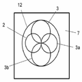
도 4(a)는 본 발명의 실시예에 따른 도 3 배열의 변화의 평면도를 도시한다. 도 4(a)의 자속 패드는 3개의 코일들(2, 3, 3a) 및 수정된 페라이트(5) 배열을 포함한다. 그 외, 도 4(a)의 패드의 구성은 일반적으로, 아래에서 위로(도 3의 상부 도면과 비교할 때), 베이스 판(7)(바람직하게는 알루미늄), 스페이서(6)(바람직하게는 유전체), 페라이트 재료(5)를 포함한 코어(4), 실질적으로 동일 평면 코일들(2, 3, 3a) 및 커버(8)(바람직하게는 유전체)를 포함한, 도 3의 BPP 패드의 것에 따른다. 주요 차이는 모든 3개의 코일들의 중심들 또는 극들이 삼각형 배열로 서로 실질적으로 동일 거리로 이격되도록 부가 코일(3a)이 코일(2) 위 또는 아래에 또는 코일(3) 위에 위치된다는 것이다. 더욱이, 코어(4)의 구성이 적응되며 각각의 세트 사이에서 60°의 오프셋 또는 실질적으로 60°를 갖고 배열된 페라이트들(5)의 3개의 세트들을 포함하며, 여기에서 각각 3개의 페라이트 세트들은 각각의 쌍들의 코일들(2, 3, 및 3a)의 중심 사이에서 연장된 축과 실질적으로 평행하여 연장된다.Figure 4 (a) shows a top view of the variation of the arrangement of Figure 3 according to an embodiment of the invention. The flux pad of Figure 4 (a) includes three
도 4(b)는 도 4(a)의 실시예의 변화를 예시하며, 여기에서 상기 코어는 중심에서의 등변 삼각형에 형성하는, 코일들의 중심들 사이에서 가상선들의 각각을 따라 단일 페라이트 스트립 또는 바(5)를 포함한다. 이 실시예에서 판(7)은 패딩을 포함하여, 실질적으로 중첩 코일들(2, 3, 및 3a)의 외주와 부합하는 형태를 가진다. Fig. 4 (b) illustrates a variation of the embodiment of Fig. 4 (a) wherein the core is a single ferrite strip or bar along each of the imaginary lines between the centers of the coils, (5). In this embodiment, the
도 5는 본 발명의 또 다른 실시예의 평면도를 도시한다. 도 5의 배열은 도 4의 것들과 실질적으로 동일하지만 코어(4) 내에 4개의 코일들(2, 3, 3a, 3b) 및 수정된 페라이트(5) 배열을 포함한다. 부가 코일(3b)은 코일들(2, 3, 및 3a) 위에, 아래에 또는 그 사이에 위치될 수 있다. 도시된 배열에서, 페라이트 격자는 그리드를 형성하기 위해 90°만큼 또는 실질적으로 90°만큼 다른 것으로부터 오프셋된 일 세트의 페라이트들과 함께 사용된다.Figure 5 shows a top view of yet another embodiment of the present invention. The arrangement of FIG. 5 is substantially identical to that of FIG. 4, but includes four coils (2, 3, 3a, 3b) and a modified ferrite (5) arrangement in the core (4). The
도 3의 배열과 마찬가지로, 코일들 사이에서의 중첩의 범위는 원하는 분리를 획득하기 위해 변경될 수 있다. 보다 특히, 적어도 3개의 코일들 중 하나 이상은 고정된 또는 각각의 고정된 주파수로 미리 결정된 전류를 갖고 및 적어도 3개의 코일들 중 다른 또는 다른 것들에서의 전압을 최소화하기 위해 변경된 적어도 3개의 코일들 중 다른 또는 다른 것들을 갖고 활성화될 수 있다. 실제로 이러한 중첩을 달성하기 위해, 바람직하게는 페라이트들(5)은 먼저 제자리에 고정되어야 한다(페라이트들(5)의 위치 및 형태에 대한 임의의 변화는 상호 결합이 최소화됨을 보장하기 위해 필요한 코일들 사이에 요구된 중첩에 영향을 줄 것이기 때문에). 코일들(2, 3, 및 3A)의 각각의 형태 및 크기는 바람직하게는 동일해야 한다(본 발명이 이에 제한되지 않을지라도). 코일(2)이 위치가 고정된다면, 코일(3)은 코일(2)을 활성화시키는 동안 도시된 상대적인 위치로 이동될 수 있다. 양쪽 코일들의 이상적인 상대적 위치를 결정하기 위해, 코일 2의 활성화로부터 코일(3)로 결합된 개방 회로 전압은 쉽게 측정될 수 있으며 코일 2에 대한 코일 3의 적절한 움직임을 갖고 최소로(이상적으로 0) 감소될 수 있다. 일단 코일들(2, 3)의 위치가 고정된다면, 코일(3a)은 일반적으로 도 4(a)에 도시된 위치에 부가될 수 있다. 코일(3a)이 이제 활성화될 수 있으며 코일들(2, 3)에 결합된 전압들이 모니터링될 수 있다. 양쪽 코일들(2, 3) 모두에 대한 코일(3a)의 위치를 조정함으로써, 결합된 전압들은 최소(이상적으로 0)로 감소되어야 하며, 이 포인트에서 그것의 위치가 고정된다.As with the arrangement of FIG. 3, the range of overlap between the coils can be varied to obtain the desired separation. More particularly, at least one of the at least three coils has a predetermined current at a fixed or respective fixed frequency and at least three coils that have been modified to minimize the voltage at the other or at least one of the three coils Lt; RTI ID = 0.0 > and / or < / RTI > In practice, in order to achieve this superposition, preferably the
원형 코일들이 도 4 및 도 5에 도시되지만, 본 발명은 상기 형태의 코일들에 제한되지 않는다. 단지 예로서, 코일들은 대안적으로 일반적으로 타원형, 정사각형 또는 직사각형 구성을 가질 수 있다. 또한, 동일한 패드 내에서의 상이한 코일들은 상이한 구성들을 가질 수 있다. 예를 들면, 도 4(a) 배열을 참조하면, 코일(2)은 타원형이며 코일들(3, 3a)은 원형일 수 있다. 더욱이, 도면들의 원형 코일들의 횡 방향 간격은 인접한 코일들의 중심들 사이에서 연장된 가상 선들 또는 축들이 실질적으로 등변 삼각형 또는 정사각형 형태를 형성할 수 있도록 실질적으로 동일 거리일 수 있지만, 이것은 반드시 그 경우이도록 요구하지 않는다. Circular coils are shown in Figures 4 and 5, but the invention is not limited to coils of this type. By way of example only, the coils may alternatively have a generally elliptical, square or rectangular configuration. Also, different coils within the same pad may have different configurations. For example, referring to the arrangement of Fig. 4 (a), the
또한, 특정한 페라이트(5) 배열들이 도 4 및 도 5에 도시되지만, 본 발명은 이에 제한되지 않는다. 다른 배열들이 원하는 방식으로 상기 필드를 향하게 하도록, 또는 보다 특히 충분한 크기의 페라이트 재료의 단일 시트를 포함하여, 3개 이상의 상호 분리된 코일들의 극들 사이에서의 낮은 자기 저항이 경로를 제공하도록 고안될 수 있다. 그러나, 페라이트 재료의 시트와 대조적으로 페라이트 스트립들의 사용은 플럭스를 제어하는 것에 대하여 유사한 성능을 제공하며 따라서 적절하게 구성된 스트립들은 비용 및 그 무게를 감소시키기 위해 선호될 수 있다는 것이 발견되었다. 다른 한편으로, 페라이트 재료의 시트를 포함한 코어는 더 얇을 수 있으며 다른 애플레이션들에서 선호될 수 있고, 그것이 단지 극들 사이에서만 낮은 자기 저항의 경로를 제공한다는 것을 보장하기 위해 성형될 수 있다. Further, although specific ferrite (5) arrays are shown in Figs. 4 and 5, the present invention is not limited thereto. The low magnetoresistance between the poles of three or more mutually separated coils, including a single sheet of ferrite material, more particularly of sufficient size, can be designed to direct the other arrays in the field in a desired manner, or more particularly, have. However, it has been found that the use of ferrite strips in contrast to sheets of ferrite material provides similar performance for controlling flux, and thus suitably constructed strips can be preferred to reduce cost and its weight. On the other hand, a core comprising a sheet of ferrite material may be thinner and may be preferred in other applications, and it may be molded to ensure that it only provides a path of low magnetoresistance between the poles.
도 4 및 도 5에 도시된 바와 같이, 페라이트 스트립들이 사용되면, 이것들은 인접한 코일들의 중심들 사이에서 연장된 가상 선 또는 축을 통과하거나 또는 그에 평행하도록 배열되는 것이 바람직하다. 따라서, 페라이트 스트립들의 어레이들이 제공될 수 있으며, 각각의 어레이는 그렇게 하나 이상의 쌍들의 상기 코일들에 맞게 정렬되도록 구성된다(즉, 코일 중심들 사이에서 연장된 가상 선들 또는 축들과).As shown in FIGS. 4 and 5, if ferrite strips are used, they are preferably arranged to pass through or parallel to imaginary lines or axes extending between the centers of adjacent coils. Thus, arrays of ferrite strips may be provided, and each array is thus configured to align with one or more of the pairs of coils (i.e., with imaginary lines or axes extending between the coil centers).
일반적으로, 페라이트 재료가 코일들의 에지들을 넘어 연장되는 것이 바람직하다(적어도 도 4 및 도 5에 도시된 바와 같이). 그러나, 본 발명은 이에 제한되지 않으며 특정한 애플리케이션에 의존하여 상이하게 구성될 수 있고 상기 코일들은 사실상 페라이트 재료보다 더 큰 면적에 걸쳐 연장될 수 있다. Generally, it is desirable that the ferrite material extend beyond the edges of the coils (at least as shown in Figures 4 and 5). However, the present invention is not so limited and may be configured differently depending on the particular application, and the coils may extend substantially over a larger area than the ferrite material.
일 실시예에 따르면, 페라이트 재료는 단지 코일들의 선택된 영역들에서 코일들의 외부 말단부를 넘어 연장되며, 상기 선택된 영역들은 상기 가상 선들이 상기 코일들을 교차하는 곳에 있거나 또는 그에 근접한다(도 3 참조). 부가적으로 또는 대안적으로, 상기 코일들 중 하나 이상은 페라이트들의 범위를 넘어, 바람직하게는 상기 이전에 언급된 선택된 영역들의 바깥쪽으로 연장될 수 있다(다시, 도 3 참조).According to one embodiment, the ferrite material extends beyond the outer ends of the coils only in selected areas of the coils, and the selected areas are at or near the imaginary lines intersecting the coils (see FIG. 3). Additionally or alternatively, one or more of the coils may extend beyond the range of ferrites, preferably outwardly of the previously mentioned selected regions (again, see FIG. 3).
도 4 및 도 5를 참조하면, 페라이트들이 도시된 바와 같이 스트립들의 어레이들을 하나를 다른 것 위에 포함하는 것이 가능하지만, 바람직하게는, 페라이트들은 단일 층에서 원하는 패턴을 형성하도록 구성된다. 예를 들면, 도 5를 참조하면, 페라이트들은 페이지(수직 페라이트들) 위 및 아래로 연장된 페라이트들이 도시된 바와 같으며 좌측에서 우측으로 페라이트들(수평 페라이트들)이 그 후 각각 수직 페라이트들 사이에서의 갭에 걸쳐 연장되는 복수의 보다 짧은 페라이트들에 의해 형성되도록, 바람직하게는 수평 소자들의 단부들이 인접한 수직 페라이트들에 인접하거나 또는 실질적으로 인접하도록 배열될 수 있다.4 and 5, it is preferred that the ferrites are configured to form the desired pattern in a single layer, although it is possible for the ferrites to include arrays of strips one on top of the other as shown. For example, referring to FIG. 5, ferrites are shown as ferrites extending above and below the page (vertical ferrites) and from left to right, ferrites (horizontal ferrites) Such that the ends of the horizontal elements are adjacent or substantially adjacent to adjacent vertical ferrites so that they are formed by a plurality of shorter ferrites extending across the gap in the vertical ferrites.
이러한 방식으로 페라이트들을 형성하는 것은 코어의 두께 및 무게를 감소시킨다.Formation of ferrites in this manner reduces the thickness and weight of the core.
페라이트들이 그 외 구성될 수 있다는 것이 이해될 것이다. 예를 들면, 다시 도 5 예를 참조하면, 스트립들은 그것들이 중첩의 영역들에서 보다 얇도록 가변 두께를 가질 수 있다. 단차로서 두께를 감소시키는 것은 상이한 페라이트 소자들이 서로 맞물리게 할 수 있다.It will be appreciated that the ferrites may be otherwise configured. For example, referring again to Figure 5, the strips may have a variable thickness such that they are thinner in overlapping regions. Reducing the thickness as a step can cause different ferrite elements to engage with each other.
이전 3개의 단락들에서 도 5에 관하여 설명된 페라이트 배열들의 예들은 도 5 배열에 제한되도록 의도되지 않으며 도 4 배열과 유사한 것들 또는 부가 코일들이 부가되는 보다 복잡한 페라이트 배열을 요구하는 것들과 같이 다른 요구된 페라이트 배열들에 대한 발명 없이 적응될 수 있다.5 are not intended to be limited to the arrangement of FIG. 5 and are not intended to limit the scope of the present invention to other arrangements such as those that require a more complex ferrite arrangement, ≪ / RTI > ferrite arrays.
또한, 페라이트의 각각의 스트립은 페라이트 재료의 하나 이상의 조각으로부터 형성될 수 있다. 따라서, 페라이트 재료의 보다 작은 스트립들 또는 조각들이 각각 보다 큰 조각을 형성하기 위해 서로 인접하거나 또는 실질적으로 인접할 수 있다.Further, each strip of ferrite may be formed from one or more pieces of ferrite material. Thus, smaller strips or pieces of ferrite material may be adjacent or substantially contiguous to each other to form a larger piece.
부가적으로 또는 대안적으로, 인접한 페라이트 부분들 사이에서의 통합의 정도가 증가될 수 있다. 예를 들면, 페라이트 배열은 원하는 대로 제거된 그것의 부분들을 갖고 하나 이상의 시트들의 페라이트 재료로부터 형성될 수 있다. Additionally or alternatively, the degree of integration between adjacent ferrite portions can be increased. For example, a ferrite arrangement may be formed from a ferrite material of one or more sheets having its portions removed as desired.
추가의 코일들이 또한 원하는 대로 부가될 수 있다.Additional coils may also be added as desired.
도 7은 도 4에 도시된 패드를 구동하기 위해 필요한 가능한 파워 서플라이 배열을 도시한다. 도시된 바와 같이 첨자들(2, 3 및 3A)은 도 4에서의 코일들(2, 3, 및 3A)에 대한 인버터 토폴로지 연결을 나타낸다. FIG. 7 shows a possible power supply arrangement needed to drive the pad shown in FIG. As shown,
본 발명의 적어도 3개의 코일들을 사용하는 이점은 패드가 다중 모드들에서 사용될 수 있다는 것이다. 예를 들면, 정지된 차량 충전 애플리케이션에 대해, 충전 패드의 적어도 3개의 코일들의 단일 코일이 작은 다용도 차량 상에서 작은 수신기에 전력을 결합시키기 위해 활성화될 수 있으며, 여기에서 활성화되도록 선택된 코일은 차량 상에서의 수신기에 최상으로 결합되는(즉, 최상으로 정렬되는) 코일에 의존한다. 대안적으로, 모든 코일들은 서로 동위상으로 활성화될 수 있어서, 대형 차량 또는 보다 빠른 충전을 요구하는 것에 동력을 공급하기 위해 보다 큰 정지된 시간 변화 필드를 생성한다. 또한, 상기 코일들(바람직하게는 3개)은 슬라이딩 공간 변화 및 시간 변화 필드를 생성하기 위해 3 위상 시스템(즉, 각각 120도 다른 위상)에서 사용될 수 있거나 또는 다수의 선택된 코일들이 단일 상 시스템에서 활성화될 수 있다(즉, 정지된 시간 변화 필드를 생성하기 위해).An advantage of using at least three coils of the present invention is that the pad can be used in multiple modes. For example, for a stationary car charging application, a single coil of at least three coils of a charging pad may be activated to couple power to a small receiver on a small utility vehicle, wherein the coil selected to be activated is a Lt; RTI ID = 0.0 > best < / RTI > Alternatively, all the coils can be activated in phase with each other, creating a larger stationary time-varying field to power a large vehicle or requiring a faster charge. In addition, the coils (preferably three) may be used in a three-phase system (i.e., each 120 degrees different phase) to create sliding space change and time varying fields, or multiple selected coils may be used in a single phase system (I.e., to generate a stationary time varying field).
또 다른 모드에서, 충전 패드의 코일들은 픽-업(예로서, 충전될 차량 상에서)의 배향 및/또는 정렬에 의존하여 활성화될 수 있다. 이 모드에서, 코일들의 모두 또는 서브세트가 사용 중에 활성화될 수 있다. 예를 들면, 코일들의 쌍들은 도 3의 BPP 패드 배열마다, 픽업에 의해 가장 효과적으로 수신된 필드를 생성하기 위해 활성화될 수 있다. 활성화된 코일들의 쌍은 예를 들면, 픽업의 움직임을 보상하기 위해 필드를 수정하도록 변화될 수 있다. 일 실시예에 따르면, 적어도 3개의 코일들을 포함한 패드의 코일들의 쌍들은 그것이 가장 유효한 필드를 생성한다면 선택적으로 활성화될 수 있다(순차적으로 포함하여).In another mode, the coils of the charge pad may be activated depending on the orientation and / or alignment of the pick-up (e.g., on the vehicle to be charged). In this mode, all or a subset of the coils can be activated during use. For example, the pairs of coils may be activated to generate the most effectively received field by the pickup, per BPP pad arrangement of FIG. The pair of activated coils may be changed, for example, to modify the field to compensate for the movement of the pickup. According to one embodiment, pairs of coils of a pad including at least three coils may be selectively activated (including sequentially) if it generates the most valid field.
적어도 3개의 코일들의 존재는 또한 충전 패드에 의해 생성된 필드의 개선된 조향을 가능하게 한다. 또한 또는 복수의 코일들의 단지 선택된 코일들만을 활성화시키는 것에 대한 대안으로서, 상이한 코일들이 상이한 레벨들로 활성화될 수 있으며, 그에 의해 말하자면, 충전이 제공되는 차량들의 주차시 변화들로 인해서와 같이, 충전 패드와의 픽업의 오정렬을 수용하기 위해 선택된 방향으로 필드를 "조향시킨다".The presence of at least three coils also enables improved steering of the field generated by the charging pad. Alternatively, or as an alternative to activating only only selected coils of a plurality of coils, different coils may be activated at different levels, thereby causing the charge "Steers" the field in a selected direction to accommodate misalignment of the pickup with the pad.
적어도 3개의 코일들의 사용은 부가적으로 또는 대안적으로 적어도 부분적으로 검출된 위치에 의존하여, 적절한(이상적으로 최적의) 충전 체제가 구현될 수 있도록 차량 픽업의 위치를 감지하는 것을 돕는다. 이것은 WO 2011/16737호에 설명된 배열들을 사용하여 어느 정도로 달성 가능하지만, 부가 코일들의 포함은 검출된 위치의 보다 큰 정확도를 제공하며 위치가 적어도 2개의 치수들에서 결정될 수 있게 한다. The use of at least three coils additionally or alternatively, depending at least partially on the detected position, helps to detect the position of the vehicle pickup so that a suitable (ideally optimal) charging regime can be implemented. This is achievable to some extent using the arrangements described in WO 2011/16737, but the inclusion of additional coils provides greater accuracy of the detected position and allows the position to be determined in at least two dimensions.
따라서, 부가의, 분리된 코일들의 사용은 본 발명의 장치가 코일들의 모두 또는 서브세트로 하여금 사용될 수 있게 함으로써 사용될 수 있는 방식들로 증가된 가요성을 위해 제공하며 동작의 모드를 변경함으로써 및/또는 달성된 필드의 개선된 조향/위치 결정을 통해(다수의 치수들에서 및/또는 보다 큰 면적에 걸쳐 제어 가능하다는 것 및/또는 픽업 위치의 보다 양호한 결정 및/또는 그것의 결과로서 필드의 적응화에 대하여 개선된) 개선된 전력 전송을 위해 추가로 제공한다.Thus, the use of additional, separate coils provides for increased flexibility in such a way that the device of the present invention can be used by making all or a subset of the coils available and by changing the mode of operation and / Or through improved steering / position determination of the achieved field (controllable in multiple dimensions and / or over a larger area and / or better adaptation of the field as a result of the better determination of the pick-up position and / Lt; / RTI > for improved power transmission).
3-상 모드에서 도 4의 삼각형 배열들을 동작시키는 것은, 그것이 높은 전력 전송이 가능하기 때문에, 특히 유용하고, 가변적인 제 2 정렬들에 대처하기 위한 능력을 소유하며, 원거리 장에서 내재된 필드 소거(즉, 누설이 낮고/없는)를 가진다.Operating the triangular arrangements of FIG. 4 in the three-phase mode is particularly beneficial because it allows high power transmission, possesses the ability to cope with the second arrangements that are variable, (I.e., low leakage / no leakage).
본 발명의 실시예들은 "충전 패드"(즉 1차 측면 권선)로서 사용하기 위한 특정한 애플리케이션을 갖지만 동일하거나 또는 유사한 배열들이 다시 픽업의 코일들 사이에서의 분리의 결과로서 개선된 전력 전송 특성들을 갖고, 픽업을 위해 사용될 수 있다는 것이 앞서 말한 것으로부터 주의될 것이다. 이러한 실시예들에서, 코일들은 파워 서플라이보다는, 픽업에 전기적으로 결합되며 그에 의해 제어될 것이고, 상기 픽업 제어기는 픽업 코일들로부터 수신된 전력을 로드에 전달하도록 동작 가능하다. 제어기는 통상적으로 파워 서플라이의 인버터들보다는, 제어 가능한 정류기 또는 정류기들을 포함할 것이다. Embodiments of the present invention have specific applications for use as "charge pads" (i.e., primary side windings), but identical or similar arrangements have improved power transfer characteristics as a result of separation between the coils of the pickup It will be noted from the foregoing that it can be used for pickup. In these embodiments, the coils are electrically coupled to and controlled by the pick-up rather than the power supply, and the pick-up controller is operable to deliver the power received from the pick-up coils to the load. The controller will typically include controllable rectifiers or rectifiers, rather than inverters of the power supply.
예를 들면, 근본적으로 도 7의 것과 동일한 도 8의 회로가 또한 이러한 경우에 또한 전기 자동차의 배터리에 걸칠 수 있는 DC 커패시터에 걸쳐 연결된 로드로의 전력 전송을 가능하게 하기 위해 패드의 출력에서 사용될 수 있다. 각각의 수신기 코일로부터 이용 가능한 전력이 모니터링될 수 있으며, 작다면, 각각의 인버터 브리지에서의 하부 스위치들이 상기 수신기 코일을 분리하며 그 외 그것의 동작으로부터 발생할 임의의 손실들을 제거하기 위해 닫힐 수 있다.For example, essentially the circuit of Fig. 8, which is essentially the same as that of Fig. 7, can also be used at the output of the pad to enable power transfer to the load across the dc capacitor, have. The available power from each receiver coil can be monitored and if it is small, the bottom switches in each inverter bridge can be closed to isolate the receiver coil and to eliminate any losses that may arise from its operation.
본 발명의 다른 실시예들에서, 1차 및/또는 2차 패드들은 가역성일 수 있으며, 여기에서 상기 패드는 또 다른 패드로부터/로 전력을 수신하거나 또는 전달하기 위해 코일들과 선택적으로 전도하도록 동작될 수 있다. 도 8의 회로는 다시 1차로 전력 흐름을 역전시키기 위해 쉽게 사용될 수 있지만, 주 유틸리티 서플라이로 다시 이러한 전력 흐름을 동기화시키기 위해, 도 7의 3상 정류기가 적절한 가역성 정류기로 대체될 필요가 있을 것이다.In other embodiments of the invention, the primary and / or secondary pads may be reversible, wherein the pad is operable to selectively conduct with the coils to receive or transmit power to / from another pad . The circuit of FIG. 8 may be readily used to reverse power flow primarily again, but to synchronize this power flow back to the main utility supply, the three-phase rectifier of FIG. 7 would need to be replaced with a suitable reversible rectifier.
가역성 전력 흐름이 불필요한 경우에, 보다 단순한 2차 회로가 사용될 수 있으며, 그 예가 도 9에 도시된다. 각각의 코일의 출력에서, 동조 커패시터가 각각의 AC 회로를 공진으로 이끌기 위해 직렬 또는 병렬 또는 양쪽 모두로 사용될 수 있다. 여기에서 병렬 공진 회로가 설계시 요구된다면 각각의 코일로부터 전류를 높이기 위해 선택적 직렬 커패시턴스와 함께 도시된다. 이들 동조된 회로들의 각각의 출력은 그 후 로드에 대한 스위치(S)를 사용하여 정류되고, 필터링되며(공통 Ldc 및 Cdc를 사용하여) 조절된다. 코일들 중 임의의 것에 결합된 전력이 낮은 것으로 결정된다면, 각각의 정류기의 기저에서 두 개의 스위치들이 나머지 코일들 중 하나에서의 전력 전송에 영향을 미치지 않고 회로로부터 상기 코일을 분리하기 위해 턴 온되며 사용될 수 있고, 그에 의해 상기 회로와 연관된 임의의 손실을 상당히 제거한다. 각각의 코일로부터의 이러한 전력 전송은 정류기들의 각각에서 AC 전류의 크기를 측정함으로써 쉽게 결정될 수 있다. 출력 다이오드는 Cdc에서의 에너지가 이들 스위치들이 턴 온될 때 회로에서의 스위치들 중 임의의 것을 통해 바람직하지 않게 방전되지 않음을 보장한다. 스위치(S)는 요구된다면 및 요구될 때 총 전력 흐름을 조절하며 모든 3개의 코일들을 분리하는 것 모두를 하기 위해 사용된다. In the case where a reversible power flow is not required, a simpler secondary circuit can be used, an example of which is shown in Fig. At the output of each coil, a tuning capacitor can be used in series, in parallel, or both to drive each AC circuit to resonance. Where a parallel resonant circuit is shown with optional series capacitance to increase current from each coil if required in design. The output of each of these tuned circuits is then rectified, filtered and adjusted (using the common L dc and C dc ) using the switch S for the load. If it is determined that the power coupled to any of the coils is low, then at the base of each rectifier two switches are turned on to disconnect the coil from the circuit without affecting the power transmission in one of the remaining coils , Thereby substantially eliminating any losses associated with the circuit. This power transfer from each coil can be easily determined by measuring the magnitude of the AC current in each of the rectifiers. The output diodes ensure that the energy at C dc is not undesirably discharged through any of the switches in the circuit when these switches are turned on. The switch S is used to both regulate the total power flow when required and required and to isolate all three coils.
본 발명의 IPT 패드가 자기장을 생성하는 1차 측 자기 장치로서 구성되는 임의의 실시예에서, 그것은 바람직하게는 2차 패드의 자기 구성, 배향, 및 변위(횡 방향 또는 그 외)에 관계없이 가능한 한 효과적으로 2차 또는 수신 패드에 전력을 결합한다. 2차 패드는 차량, 이동 전화, 랩탑 또는 다른 이러한 전기 디바이스 내에 통합될 수 있어서, 만약에 있다면 이들 가변 인자들에 걸쳐 적은 제어를 제공한다. 즉, 1차 패드는 바람직하게는 그것이 가능한 2차 패드들의 범위에 및/또는 특정한 애플리케이션에서 적정하게 예상될 수 있는 광범위한 상태들 하에서 전력을 전달하도록 적응된다는 점에서 범용적이거나 또는 근-범용적이도록 설계된다.In any embodiment in which the IPT pad of the present invention is configured as a primary side magnetic device producing a magnetic field, it is preferably capable of generating a magnetic field in any possible manner regardless of the magnetic configuration, orientation, and displacement (transverse or otherwise) One effectively combines power to the secondary or receiving pad. The secondary pads can be integrated into a vehicle, mobile phone, laptop or other such electrical device, providing less control over these variable factors, if any. That is, the primary pad is preferably adapted to be universal or near-universal in that it is preferably adapted to deliver power under a wide range of possible secondary pads and / Is designed.
원형 2차 패드를 가진 디바이스가 1차에 대하여 가변 최저 지상고 또는 변위와 근접할 때, 예를 들면, 1차로부터 2차로 전력을 최상으로 결합시키도록 시스템을 구성하기 위한 요구가 있을 것이다. 디바이스가 접지에 매우 근접하다면, 최상 정렬에 있는 코일이 선택될 수 있는 반면, 2차가 멀러 떨어져 있다면, 코일들의 그룹은 1차 및 2차 사이에서의 보다 양호한 결합을 생성하기 위해 동위상으로 또는 다중상 시스템으로서 함께 활성화될 수 있다. 또 다른 중요한 고려사항은 가열할 수 있는 외부 오브젝트들 또는 이들 누설 필드들의 대상이 될 수 있는 인간들 또는 동물들이 있는 경우와 같이, 관심 거리들에서의 자기장 누설을 제한하거나 또는 최소화한다. There will be a need to configure the system to best match power, for example, from primary to secondary, when a device with a circular secondary pad is close to a variable minimum ground level or displacement for the primary. If the device is very close to ground, the coils in the topmost alignment can be selected, whereas if the secondary is farther away, the group of coils can be in phase or multi-phase to produce better coupling between the primary and secondary Can be activated together as a phase system. Another important consideration is to limit or minimize magnetic field leakage at points of interest, such as when there are humans or animals that can be heated external objects or these leak fields.
국제 특허 공개 번호들(WO 2010/090539호 또는 WO 2010/090538호)에 개시된 것들과 같이 자기학들을 양극화하는 2차 디바이스들에 대해, 이러한 디바이스의 배향은 동일한 관심사이다. 이러한 상황들에서, 1차 코일들은 최상의 결합을 보장하기 위해 활성화될 수 있으며 코일들이 별도로 제어되는 경우에, 최상의 배향을 가진 단일 상 양극화된 코일이 활성화될 수 있거나, 또는 다상 동작이 지정된 애플리케이션에 대한 최소 누설을 갖고 최고 결합 및 전력 전송을 보장하면서 전력을 전송하기 위해 사용될 수 있다. 최저 지상고, 정렬 및 회전에서의 변화들은 모두 어떤 상태들 하에서 어떤 코일들이 선택되는지에 대한 선택에 영향을 미칠 수 있다. 바람직하게는 1차 접지 측에서의 코일들은 그것들 사이에서의 최소 상호 결합을 가지며, 따라서 임의의 구성이 수용 가능하며 가까운 코일들에 나타나며 원하는 플럭스 형태의 생성 및 전력 흐름을 방해하는 이웃 코일들의 활성화로부터의 결합된 전압들과 같은 유해 효과들 없이 사용될 수 있다. 그러나, 장치 사이에서의 전력 결합이 제어 가능하며 누설이 애플리케이션을 위해 요구된 바와 같이 포함되는 경우에만, 몇몇 상호 교차-결합은 충분히 작다면 특정한 구성들에서 허용 가능할 수 있다. For secondary devices polarizing magnetics, such as those disclosed in International Patent Publication Numbers (WO 2010/090539 or WO 2010/090538), the orientation of such devices is of the same concern. In such situations, the primary coils can be activated to ensure the best coupling and, if the coils are separately controlled, a single phase polarized coil with the best orientation can be activated, or a polyphase operation can be activated for a given application Can be used to transmit power with minimal leakage and ensuring maximum coupling and power transmission. The changes in minimum ground clearance, alignment, and rotation all can affect the choice of which coils to select under which conditions. Preferably, the coils at the primary ground side have a minimum mutual coupling therebetween, so that any configuration is acceptable and appears in the near coils and the coupling from the activation of the neighboring coils, which interferes with the generation and power flow of the desired flux form And can be used without harmful effects such as voltages being applied. However, only if the power coupling between the devices is controllable and leakage is included as required for the application, then some inter-crossover coupling may be acceptable in certain configurations if small enough.
도 4 및 도 5의 코일 배열들의 다수의 다른 실시예들 또는 변화들이 본 발명의 범위로부터 벗어나지 않고 가능하다는 것이 이해될 것이다. 다수의 이러한 실시예들 및 변화들은 에로서 이하에 간단히 설명된다. It will be appreciated that many other embodiments or variations of the coil arrangements of Figures 4 and 5 are possible without departing from the scope of the present invention. Many such embodiments and variations are briefly described below as follows.
코어 및/또는 도전성 판을 포함한 백킹은 필드들이 단일 면이며 그것들이 2차 자기 디바이스에 대한 결합을 강화하도록 공간에서 맞춰질 수 있음을 보장하기 위해 유용하지만, 페라이트 스트립들(5)은 본 발명에 필수적이지 않으며, 특히 이중-면 플럭스 필드가 용인 가능하거나 또는 심지어 바람직할 수 있는 경우에 생략될 수 있다.Backing, including cores and / or conductive plates, is useful to ensure that the fields are single-sided and that they can fit in space to enhance bonding to the secondary magnetic device, but the ferrite strips 5 are essential to the present invention And may be omitted, especially where the double-sided flux field is acceptable or even desirable.
도 10 및 도 11은 각각 도 4 및 도 5의 실시예들의 변화들을 도시하며, 여기에서 페라이트 스트립들(5)은 생략된다. 코어 없이 코일들로부터 적절한 거리를 제공받은 알루미늄 또는 구리와 같은 도전성 재료로 만들어진 뒤판은 손실들을 최소화하면서 실드로서 작용할 수 있다. 판(7)은 그러므로 예를 들면 페라이트 로딩된 인쇄 회로 보드(PCB) 및/또는 알루미늄 판을 포함할 수 있다. 대안적으로, 코일들 위 및 아래 양쪽 모두에 위치되는 둘 이상의 2차들에 결합하도록 요구할 수 있는 1차 패드에서와 같이, 양쪽 방향들에서의 필드들을 갖기 위한 바람이 있는 애플리케이션들이 있을 수 있다. 이러한 경우들에서, 페라이트 또는 실드들은 이러한 결합을 가능하게 하기 위해 전체적으로 제거될 수 있다. 다른 경우들에서, 구조 아래의 필드들은 임의의 구조에 바람직하지 않게 결합할 수 없을 것이며 그러므로 임의의 손실들을 야기하지 않을 것이다. 1차의 양쪽 측면들 상에 존재하는 필드들을 갖는 것이 2차 디바이스에 대한 결합을 감소시키지만, 그것은 임의의 상당한 손실을 생성하지 않으며 그러므로 1차 패드를 생성하는 비용을 최소화하기 위해 몇몇 상황들에서 선호될 수 있다.Figures 10 and 11 show variations of the embodiments of Figures 4 and 5, respectively, wherein the ferrite strips 5 are omitted. A backplane made of a conductive material such as aluminum or copper that has been provided with an appropriate distance from the coils without a core can act as a shield while minimizing losses. The
도 12(a) 및 도 12(b)는 페라이트 스트립들(5)을 갖고 및 그것 없이, 본 발명에 따른 IPT 패드의 추가 실시예의 두 개의 변화들을 도시한다. 이 실시예에 따른 패드는 구적 코일(12)과 함께 4개의 코일들(2, 3, 3a, 및 3b)을 포함한다. 4개의 원형 코일들(2, 3, 3a, 및 3b)이 각각 정사각형의 꼭짓점들을 총괄하여 정의하는 중심을 갖는 것으로서 여겨진다면, 정사각형의 대각선으로 대향하는 코일들은 쌍극자들로서 동작하는 두 개의 직교 DDP 쌍들(도 1 및 도 2에 대하여 상기 설명된 바와 같이)을 형성하기 위해 중첩 없이 서로 인접한다. DDP 쌍들의 각각의 코일은 직교 DDP 쌍의 코일들 양쪽 모두를 중첩시키며, 두 개의 DDP 쌍들은 그에 따라 상호 분리된다. 구적 코일(12)은 또한 DDP 쌍들의 양쪽 모두로부터 상호 분리된다. 1차 구조로서, DDP 쌍들 및 구적 코일은 모두 독립적이며 또한 요구된 대로 필드를 성형하기 위해 서로를 간섭하지 않고 상이한 크기, 위상 또는 주파수를 갖고 동작될 수 있다. 2차 구조로서 DDP 또는 구적 코일들은 상이한 또는 유사한 주파수들로 개별적으로 동조될 수 있으며 전력은 애플리케이션에 기초하여 원하는 대로 및 원할 때 추출될 수 있다.Figures 12 (a) and 12 (b) show two variations of a further embodiment of an IPT pad according to the present invention, with and without ferrite strips 5. A pad according to this embodiment includes four
도 12의 실시예들의 동작의 일 가능한 모드에서, DDP 쌍들은 서로 동위상으로 동작될 수 있어서 정지된 시간 변화 자기장을 발생시킨다. 또 다른 모드에서, 한 쌍의 대각선 대향 DDP 코일들은 다른 쌍과 다른 위상으로 활성화될 수 있다. 또 다른 모드에서, 단지 하나의 DDP가 활성화될 수 있다. 추가 모드들에서, 구적 코일(12)은 DDP 쌍들 중 하나 또는 양쪽 모두와 동시에 활성화될 수 있다. 동작의 모드 및 적절한 경우, 활성화된 코일들은 바람직하게는 픽업에 의해 수신된 필드를 가장 효과적으로 생성하기 위해 선택된다. IPT 시스템은 바람직하게는 가장 효율적인 방식으로 동작시키기 위해 요구된 대로 임의의 이러한 모드 사이에서 스위칭할 수 있지만, 파워 서플라이 설계 및/또는 제어를 간소화하기 위해 단일 모드 또는 모드들의 선택에 제한될 수 있다. In a possible mode of operation of the embodiments of FIG. 12, the DDP pairs can be operated in phase with each other, resulting in a stationary time-varying magnetic field. In another mode, a pair of diagonally opposed DDP coils may be activated in a different phase than the other pair. In another mode, only one DDP can be activated. In additional modes, the
도 12(c) 내지 도 12(e)는 도 12(a) 및 도 12(b)의 실시예들의 추가 변화들을 도시한다. 도 12(c)의 실시예는 구적 코일을 생략한다. 도 12(d)는 각각의 DDP 쌍의 코일들이 반드시 동일한 크기일 필요는 없지만, 여전히 상호 분리될 수 있음을 예시한다. 구적 코일(12)은 또한 도 12(e)에 도시된 바와 같이 이 실시예에 부가될 수 있다. 코일들의 DDP 쌍들이 쌍극자들로서 동작되기 때문에, 구적 코일(12)은 이 실시예에서 DDP 상들 모두로부터 상호 분리된다. Figures 12 (c) through 12 (e) show further variations of the embodiments of Figures 12 (a) and 12 (b). The embodiment of Fig. 12 (c) omits the quadrature coil. Figure 12 (d) illustrates that the coils of each DDP pair need not necessarily be the same size, but can still be separated from each other. The
본 발명의 다양한 실시예들에 따른 IPT 패드의 코일들이 이상적으로 서로로부터 완전히 분리되지만, 몇몇 공칭 결합은 불가피할 수 있다. 검사 하에서, 표(A4)에 열거된 치수들을 가진, 도 4(b)의 IPT 패드는 예를 들면, 코일들(2, 3) 사이에서 0.15%, 및 코일들(2, 3a) 사이에서 0.08%의 최고 상호 결합 또는 결합 계수(k)를 갖는 것으로 도시된다. 그러나, 코일들 사이에서의 임의의 중요한 상호 결합은 시스템의 효율성에 심각하게 영향을 줄 것이며 상호 결합은 이상적으로 실질적으로 가능한 0에 가까워야 한다. 코일들 사이에서 측정된 상호 결합은 외부 페라이트 재료의 존재시 또는 부하 하에서 일반적으로 증가할 것이라는 것이 주의되어야 한다. 본 발명에 따른 IPT 패드는 따라서 바람직하게는 로드 또는 외부 페라이트 재료의 부재시 약 10% 미만, 및 보다 특히 약 2% 또는 심지어 1% 미만의 상호 결합을 갖도록 설계된다. 설명 및 청구항들의 목적을 위해, 구절들("상호 분리된", "상호 결합이 없는" 등)은 이러한 상호 결합들을 포함하도록 의도된다.Although the coils of the IPT pads in accordance with various embodiments of the present invention are ideally completely separate from each other, some nominal coupling may be inevitable. Under inspection, the IPT pads of Fig. 4 (b) with the dimensions listed in Table A4 are, for example, 0.15% between the
이러한 장치들에 대해 상호 분리되는 코일들을 갖기 위해 하나의 디바이스로부터 발생된 플럭스가 1차(또는 2차)에서의 이웃 코일들과 대략 등분 비례하여 들어가고 나오도록 서로에 대하여 코일들의 적절한 간격을 필요로 하며, 여기에서 이웃 코일들을 통한 순속(net flux)은 대략 0이다.In order to have coils that are mutually separated for these devices, the flux generated from one device needs a proper spacing of the coils relative to each other so that the flux enters and leaves the neighboring coils at the primary (or secondary) Where the net flux through the neighboring coils is approximately zero.
그럼에도 불구하고, 약 20%까지와 같이, 코일들 사이에서의 보다 높은 레벨의 결합은 본 발명의 범위로부터 벗어나지 않고 적어도 몇몇 애플리케이션들에서 수용 가능할 수 있다. 훨씬 더 높은 레벨들의 상호 분리는 몇몇 애플리케이션들에 대해, 특히 1차 및 2차 패드들 사이에서의 간격이 낮은 경우에 대해 용인 가능할 수 있다. 도 13 및 도 14는 예를 들면 약 20%까지의 낮은 레벨의 상호 결합이 있을 수 있는 본 발명의 실시예들을 도시한다.Nevertheless, a higher level of coupling between the coils, such as up to about 20%, may be acceptable in at least some applications without departing from the scope of the present invention. Much higher levels of mutual isolation may be acceptable for some applications, especially when the spacing between the primary and secondary pads is low. Figures 13 and 14 illustrate embodiments of the present invention that may have low levels of mutual coupling, for example, up to about 20%.
도 13(a) 내지 도 13(e)는 도 4의 3-코일 IPT 패드의 추가 변화들을 포함한 실시예들을 도시한다.Figures 13 (a) through 13 (e) illustrate embodiments including further variations of the 3-coil IPT pad of Figure 4.
도 13(a)의 IPT 패드는 이상적으로 상호 분리되지 않는, 이 경우에 코일들(2, 3, 및 3a)을 전체적으로 둘러싸는, 추가 코일(13)을 더 포함한다. 이 실시예에서 추가 코일(13)은 바람직하게는 그것의 중심 또는 극이 바람직하게는 서로로부터 상호 분리되는 코일들(2, 3, 및 3a)에 대하여 실질적으로 중심이도록 배치된다. 이 실시예에서 중심 코일(13)이 다른 코일들을 둘러싸지만, 다른 실시예들에서 실질적으로 중심 코일(13)은 이하에 설명되는 바와 같이, 3개 이상의 다른 코일들을 제한하거나 또는 부분적으로 중첩시킬 수 있다. The IPT pad of Fig. 13 (a) further comprises an
중심 코일(13)이 다른 코일들의 모두를 둘러싸거나 또는 부분적으로 중첩시킴에 따라, 그것은 동작의 모든 가능한 모드들에서 이들 코일들로부터 상호 분리되지 않을 것이다. 특히, 도 13(a)의 중심 코일(13)은 이들 코일들 중 모두 3개가 활성화될 때 코일들(2, 3 및 3a)로부터 실질적으로 상호 분리될 것이지만, 통상적으로 예를 들면, 단지 코일들(2, 3)만이 활성화될 때 상호 분리되지 않을 것이다. As the
도 13(a)의 IPT 패드는 또한 도 4의 실시예의 코어 또는 페라이트 스트립들(5)을 생략한다. 판(7)의 정사각형 형태는 또한 중심 코일(13)을 수용하기 위해 도 4의 삼각형 판(7)과 상이하게 보여질 수 있다. The IPT pad of Fig. 13 (a) also omits the core or
도 13(b)의 실시예는 도 13(a)의 것과 유사하지만, 실질적으로 직교 페라이트 스트립들(5)의 격자 또는 그리드를 포함한다. 따라서 페라이트 스트립들(5)이 도 4에 도시된 바와 같이 반드시 코일들(2, 3, 및 3a)의 중심들 사이에서의 가상 선들에 평행하여 연장될 필요가 없음이 명백할 것이다. 이전에 설명된 바와 같이, 코어는 대안적으로 페라이트 재료의 시트를 포함할 수 있다. The embodiment of Fig. 13 (b) is similar to that of Fig. 13 (a), but comprises a grating or a grid of substantially orthogonal ferrite strips 5. It will thus be clear that the ferrite strips 5 do not necessarily have to extend parallel to the imaginary lines between the centers of the
도 13(c)의 실시예는 페라이트 스트립들(5)이 중심 코일(13)의 외주면을 넘어 연장된다는 점에서 도 13(b)에 대하여 추가 수정을 포함한다. 페라이트 스트립들(5)이 중심 코일(13) 내에서 종단한다면 필드는 방사할 것이며, 이 실시예의 가늘고 긴 페라이트 스트립들(5)이 그에 따라 일반적으로 선호될 것이다. The embodiment of Figure 13 (c) includes a further modification to Figure 13 (b) in that the ferrite strips 5 extend beyond the outer circumferential surface of the
도 13(d) 및 도 13(e)는 도 4의 3-코일 패드의 추가 변화들을 도시하며, 코일들(2, 3, 및 3a)을 부분적으로 둘러싸는 중심 코일(13)을 더 포함한다. 도 13(d)는 페라이트 스트립들(5) 없이 IPT 패드의 실시예를 도시하는 반면, 도 13(e)는 코일들(2, 3, 및 3a)의 외주면으로, 또는 이를 약간 넘어 연장되는 페라이트 스트립들(5)의 격자를 포함한다.Figures 13 (d) and 13 (e) show further variations of the 3-coil pad of Figure 4 and further include a
도 14(a) 내지 도 14(d)는 예로서, 도 4의 3-코일 실시예들의 몇몇 차선의 변화들을 예시한다. 이들 실시예들에서, 코일들(2, 3, 및 3a)은 중첩하지 않으며, 그러므로 상호 결합을 가질 것이다.Figures 14 (a) - 14 (d) illustrate, by way of example, changes in several lanes of the three-coil embodiments of Figure 4. In these embodiments, coils 2, 3, and 3a do not overlap and therefore will have mutual coupling.
본 발명의 다중-코일 구조가 전력을 수신하기 위해 2차 패드로서 사용되는 경우에, 이상적으로 코일들은 모두 각각의 코일이 선택된 주파수에서 전력을 수신하기 위해 쉽게 동조될 수 있으며, 전력 전송이 최대화됨을 보장하기 위해 서로로부터 상호 분리될 것이다. 이러한 상태들 하에서, 코일이 전력을 수신하지 않을 때, 그것은 임의의 동작 손실을 감소시키기 위해, 다른 코일들의 동작에 영향을 미치지 않고 스위칭 오프될 수 있다. 그럼에도 불구하고, 2차 코일들이 완전히 상호 결합되지(독립적이지) 않는다면, 동작 회로 동조 Q(회로의 로드에 의해 분할된 코일의 리액턴스)가 낮을 경우에만, 공칭 동조가 달성될 수 있으며 동작은 여전히 이웃 코일들 사이에 몇몇 상호 결합이 있음에도 불구하고 발생할 수 있다. 이러한 코일들은 또한 스위칭 아웃될 수 있으며 이것이 인접한 코일들에서의 전력 전송에 약간 영향을 미칠 수 있지만, 이것은 그것의 구동 VA를 증가시키거나 또는 감소시키는 1차 접지 코일들의 동작에 의해 또는 로드에 대한 전력을 수정하기 위해 2차 조절기를 조정함으로써 보상될 수 있다.In the case where the multi-coil structure of the present invention is used as a secondary pad to receive power, ideally the coils can all easily be tuned to receive power at a selected frequency of each coil, Will be separated from each other to ensure that Under these conditions, when the coil does not receive power, it can be switched off without affecting the operation of other coils, to reduce any operating losses. Nevertheless, unless the secondary coils are completely mutually coupled (independent), only if the operating circuit tuning Q (the reactance of the coil divided by the load of the circuit) is low, nominal tuning can be achieved and the operation is still neighbors May occur despite some mutual coupling between the coils. These coils can also be switched out and this may have some effect on the power transmission in the adjacent coils, but this can be achieved by operation of the primary ground coils increasing or decreasing its drive VA, Can be compensated by adjusting the secondary regulator to correct the secondary regulator.
3개 이상의 상호 분리된 코일들을 포함한 본 발명의 추가 실시예에서, 그것은 몇몇 애플리케이션들에서 상이한 동조들을 가진 2차 디바스들과의 결합된 동작을 가능하게 하기 위해 상이한 주파수들로 다양한 코일들 중 하나 이상을 동조시키는 것이 바람직할 수 있다. 예를 들면, 높은 전력 전송을 위해, 코일들 중 몇몇은 다른 것들이 80kHz에서 동조될 수 있는 동안 40kHz에서의 동작을 위해 설계되며 동조될 수 있어서, 상이한 동조 주파수들에서 상이한 자기 구조들에 대한 결합을 가능하게 한다. 대안적으로, 보다 낮은 전력 전송을 위해, 예를 들면 보다 작은 기기들 또는 이동 소비자 전자 디바이스들에 대해 동일하게 달성하기 위해 몇몇 코일들은, 다른 것들이 2.4 GHzfh 동조될 수 있는 동안 800 MHz에서 동조될 수 있다(양쪽 모두 인가되지 않은 대역들)In a further embodiment of the invention involving three or more mutually isolated coils, it may be possible to use one of the various coils at different frequencies to enable combined operation with secondary devices with different tunings in some applications It may be desirable to synchronize the above. For example, for high power transmission, some of the coils may be designed and tuned for operation at 40 kHz while others can be tuned at 80 kHz, so that coupling to different magnetic structures at different tuning frequencies . Alternatively, for lower power transmission, for example, to achieve the same for smaller appliances or mobile consumer electronic devices, some coils can be tuned at 800 MHz while others can be tuned to 2.4 GHz fh (Both unauthorized bands)
표 A1: BPP의 치수들Table A1: Dimensions of BPP
공통 치수들Common dimensions
권선 폭 80 mmWinding width 80 mm
페라이트 간격 32 mmFerrite spacing 32 mm
페라이트 폭 28 mmFerrite width 28 mm
Y 코일 간격 50 mmY Coil spacing 50 mm
Y 패딩 46 mmY padding 46 mm
커버 두께 6 mm
코일 높이 4 mm
페라이트 높이 16 mmFerrite height 16 mm
스페이서 두께 6 mm
판 두께 4 mm
페라이트들의 수에 기초한 변화들Changes based on the number of ferrites
A: BBP6: 각각의 페라이트 스트립을 만들기 위해 6개의 페라이트 슬래브들을 사용함A: BBP6: use six ferrite slabs to make each ferrite strip
(BPP6) 페라이트 길 558 mm(BPP6) Ferrite wire 558 mm
(BPP6) 중첩 156 mm(BPP6) Overlay 156 mm
X 코일 간격 10 mmX Coil spacing 10 mm
X 패딩 10 mm
X padding 10 mm
B: BBP8: 각각의 페라이트 스트립을 만들기 위해 8개의 페라이트 슬래브들을 사용함B: BBP8: uses 8 ferrite slabs to make each ferrite strip
페라이트 길이 774 mmFerrite length 774 mm
중첩 74 mmOverlay 74 mm
X 코일 간격 - 83 mm(-는 중첩을 표현한다)X coil spacing - 83 mm (- represents overlap)
X 패딩 10 mm
X padding 10 mm
C: BBP10: 각각의 페라이트 스트립을 만들기 위해 10개의 페라이트 슬래브들을 사용함C: BBP10: Use 10 ferrite slabs to make each ferrite strip
페라이트 길이 930 mmFerrite length 930 mm
중첩 39 mmOverlay 39 mm
X 코일 간격 - 174 mm(-는 중첩을 표현한다)X coil spacing - 174 mm (- represents overlap)
X 패딩 110 mm(nb: 추가의 페라이트들을 맞추기 위해 패딩에 전부 200mm 부가됨)
X padding 110 mm (nb: 200 mm added to the padding to fit additional ferrites)
표 A2: DDP의 치수들Table A2: Dimensions of DDP
권선 폭 80 mmWinding width 80 mm
내부 권선 폭 120 mmInner winding width 120 mm
페라이트 간격 32 mmFerrite spacing 32 mm
페라이트 폭 28 mmFerrite width 28 mm
Y 코일 간격 10 mmY Coil spacing 10 mm
Y 패딩 46 mmY padding 46 mm
커버 두께 6 mm
코일 높이 4 mm
페라이트 높이 16 mmFerrite height 16 mm
스페이서 두께 6 mm
판 두께 4 mm
페라이트 길이 558 mmFerrite length 558 mm
X 코일 간격 10 mmX Coil spacing 10 mm
X 패 10 mm
표 A3: DDQP의 치수들Table A3: Dimensions of DDQP
권선 폭 80 mmWinding width 80 mm
내부 권선 폭 120 mmInner winding width 120 mm
페라이트 간격 32 mmFerrite spacing 32 mm
페라이트 폭 28 mmFerrite width 28 mm
Y 코일 간격 10 mmY Coil spacing 10 mm
Y 패딩 46 mmY padding 46 mm
커버 두께 6 mm
코일 높이 4 mm
페라이트 높이 16 mmFerrite height 16 mm
스페이서 두께 6 mm
판 두께 4 mm
페라이트 길이 558 mmFerrite length 558 mm
X 코일 간격 10 mmX Coil spacing 10 mm
X 패딩 10 mmX padding 10 mm
구적 코일 길이 534 mm
Quadrature coil length 534 mm
표 A4: 도 12의 IPT 패드의 치수들Table A4: Dimensions of the IPT pad of Figure 12
페라이트 길이 520 mmFerrite length 520 mm
페라이트 폭 28 mmFerrite width 28 mm
페라이트 높이 16 mmFerrite height 16 mm
페라이트 구조에 의해 형성된 등변 삼각형의 각각의 측면 200 mmEach side of the equilateral triangle formed by the ferrite structure is 200 mm
각각의 코일의 내부 직경 130 mmThe inner diameter of each coil is 130 mm
각각의 코일의 외부 직경 150 mmThe outer diameter of each coil is 150 mm
하나의 코일의 중심 포인트로부터 다른 것으로의 최고 거리 172 mmMaximum distance from the center point of one coil to another 172 mm
코일들(2, 3) 사이에서의 상호 결합 k 0.15%Mutual coupling between
코일들(2, 3a) 사이에서의 상호 결합 k 0.08%
Mutual coupling between
본 발명은 주로 전기 자동차들에 동력을 공급하거나 또는 이를 충전할 때 애플리케이션들을 참조하여 설명되지만, 본 발명은 일반적으로 유도 전력 전송에 대한 애플리케이션을 가지며, 그러므로 이에 제한되지 않지만, 이동 전화기들, 컴퓨터 디바이스들, 및/또는 컴퓨터 주변 장치들과 같은 고- 또는 저-전력 기기들 또는 소비자 전자 장치들에 무선으로 동력을 공급하거나 또는 이를 충전하는 것을 포함한 일련의 산업용 또는 소비자 애플리케이션들에 적용될 수 있다는 것이 주의된다. 인간 인터페이스 디바이스(human interface device; HID)를 참조하여 예로서, 본 발명에 따른 1차 자속 패드는 무선 마우스에 동력을 공급하거나 또는 이를 충전하기 위해 마우스 패드에 제공될 수 있거나, 또는 알려진 1차 패드로부터 전력을 수신하기 위해 마우스에 통합될 수 있다.Although the present invention is described primarily with reference to applications when powering or charging electric vehicles, the present invention generally has applications for inductive power transmission, and thus is not limited to mobile phones, computer devices And / or computer peripheral devices, or to a range of industrial or consumer applications including wirelessly powering or charging consumer electronics devices, do. With reference to a human interface device (HID), for example, a primary flux pad in accordance with the present invention may be provided on a mouse pad for powering or charging a wireless mouse, Lt; RTI ID = 0.0 > a < / RTI >
맥락이 달리 명확하게 요구하지 않는다면, 설명 및 청구항들 전체에 걸쳐, 단어들("포함하다", "포함하는 등)은 배타적인 또는 철저한 의미와 대조적으로 포괄적인 의미로, 말하자면 "이에 제한되지 않지만, 포함하는"의 의미로 해석되는 것이다.Throughout the description and the claims, unless the context clearly dictates otherwise, words (including "including", "including", etc.) are intended to be inclusive in a generic sense, as opposed to an exclusive or exhaustive sense, Quot ;, " including ", and " including. &Quot;
본 명세서에서 임의의 종래 기술에 대한 참조는 상기 종래 기술이 세계에서의 임의의 국가에서의 노력의 분야에서 공통적인 일반 지식의 부분을 형성하는 임의의 형태의 제안 또는 인지가 아니며 그것으로서 취해져서는 안된다. Reference herein to any prior art is not a suggestion or acknowledgment of any form that the prior art forms part of the general knowledge common in the field of effort in any country in the world and should not be taken as that .
본 발명은 또한 대략 애플리케이션의 명세서에, 개별적으로 또는 포괄적으로, 또는 부분들, 요소들 또는 특징들 중 하나 이상의 임의의 또는 모든 조합들로 참조되거나 또는 표시된 상기 부분들, 요소들 및 특징들에 있다고 말하여질 수 있다.The invention is also broadly referred to in the appended claims, either individually or collectively, or in the portions, elements and features referred to or indicated in any or all combinations of portions, elements or features It can be said.
앞서 말한 설명에서, 참조는 알려진 등가물들을 가진 본 발명의 특정 구성요소들 또는 정수들로 이루어지지만, 그 후 이러한 등가물들은 여기에서 개별적으로 제시된 것처럼 통합된다.In the foregoing description, reference is made to certain elements or integers of the present invention with known equivalents, but such equivalents are hereafter incorporated as if individually set forth.
본 발명은 예로서 그것의 가능한 실시예들을 참조하여 설명되지만, 수정들 또는 개선들이 본 발명의 범위 또는 사상으로부터 벗어나지 않고 그것에 대해 이루어질 수 있다는 것이 이해될 것이다.While the invention has been described by way of example and with reference to its possible embodiments, it will be understood that modifications and improvements can be made thereto without departing from the scope or spirit of the invention.
Claims (36)
적어도 3개의 코일들로서, 상기 코일들의 권선들이 실질적으로 동일한 평면에 있도록 위치된 적어도 3개의 코일들; 및
자기장이 생성되거나 또는 전력이 상기 적어도 3개의 코일들 중 복수의 쌍들의 적어도 하나에 의해 수신되도록 상기 코일들 중 둘 이상과 선택적으로 전도하도록 동작 가능한 파워 서플라이 또는 픽업 제어기를 포함하는, 자속 패드.In magnetic flux pads for generating or receiving magnetic fluxes,
At least three coils, with at least three coils positioned such that the coils of the coils are in substantially the same plane; And
A power supply or pickup controller operable to selectively conduct at least two of said coils such that a magnetic field is generated or power is received by at least one of said plurality of pairs of said at least three coils.
상기 파워 서플라이 또는 픽업 제어기는 상기 코일들 중 임의의 하나 이상으로부터 전력을 활성화시키거나 또는 수신하기 위해 상기 코일들과 선택적으로 전도하도록 동작 가능한, 자속 패드.The method according to claim 1,
Wherein the power supply or pickup controller is operable to selectively conduct with the coils to activate or receive power from any one or more of the coils.
상기 파워 서플라이 또는 픽업 제어기는 상기 적어도 3개의 코일들로부터 전력을 순차적으로 활성화시키거나 또는 수신하도록 동작 가능한, 자속 패드.The method according to claim 1 or 2,
Wherein the power supply or pickup controller is operable to sequentially activate or receive power from the at least three coils.
상기 파워 서플라이 또는 픽업 제어기는 상기 적어도 3개의 코일들의 각각에서 전류의 위상, 크기 및/또는 주파수를 독립적으로 제어하도록 동작 가능한, 자속 패드.The method according to any one of claims 1 to 3,
Wherein the power supply or pickup controller is operable to independently control the phase, magnitude and / or frequency of the current in each of the at least three coils.
상기 적어도 3개의 코일들은 서로 실질적으로 상호 분리되는, 자속 패드.The method according to any one of claims 1 to 4,
Said at least three coils being substantially mutually separated from each other.
상기 적어도 3개의 코일들은 부분적으로 중첩하는, 자속 패드.The method according to any one of claims 1 to 5,
Said at least three coils partially overlapping.
상기 적어도 3개의 코일들은 서로 실질적으로 같은 거리로 이격되는, 자속 패드.The method according to any one of claims 1 to 6,
Wherein the at least three coils are spaced substantially the same distance from each other.
3개의 실질적으로 상호 분리된 코일들을 포함하는, 자속 패드.The method according to any one of claims 1 to 7,
Comprising three substantially mutually separated coils.
상기 파워 서플라이는 복수의 모드들에서 동작 가능하며, 상기 복수의 모드들은:
단-상 모드들로서, 상기 코일들 중 하나 이상이 서로 동위상으로 활성화되는, 단-상 모드들;
2-상 모드들로서, 상기 코일들 중 하나 이상이 하나 이상의 다른 코일들과 다른 위상(out of phase)으로 동시에 활성화되는, 2-상 모드들; 및
다상 모드로서, 상기 코일들 중 3개 이상이 서로 다른 위상으로 동시에 활성화되는, 다상 모드 중 적어도 두 개를 포함하는, 자속 패드.The method according to any one of claims 1 to 8,
Wherein the power supply is operable in a plurality of modes, the plurality of modes comprising:
End-to-end modes in which at least one of the coils is activated in phase with respect to one another;
Two-phase modes, in which at least one of the coils is simultaneously activated out of phase with one or more other coils; And
A multiphase mode, wherein at least two of the coils are simultaneously activated in different phases.
자기 투과성 코어를 더 포함하며, 상기 적어도 3개의 코일들은 상기 코어와 자기적으로 연관되는, 자속 패드.The method according to any one of claims 1 to 9,
And a magnetic permeable core, wherein the at least three coils are magnetically associated with the core.
실질적으로 중심에 배치되며 상기 적어도 3개의 코일들을 둘러싸거나 또는 부분적으로 중첩하는 추가 코일을 더 포함하는, 자속 패드.The method according to any one of claims 1 to 10,
Further comprising an additional coil disposed substantially centrally and surrounding or partially overlapping the at least three coils.
상기 추가 코일은 동작의 적어도 하나의 모드에서 상기 적어도 3개의 코일들로부터 실질적으로 상호 분리되는, 자속 패드.The method of claim 11,
Wherein the additional coils are substantially mutually separated from the at least three coils in at least one mode of operation.
각각이 서로 실질적으로 동일 거리로 이격된 3개의 중첩하며 실질적으로 상호 분리된 코일들, 및
상기 3개의 코일들의 극들 사이에서 저 저항 자기 경로를 제공하는 자기 투과성 코어를 포함하는, 자속 패드.The method according to claim 1,
Three overlapping and substantially mutually separated coils, each substantially spaced at the same distance from each other, and
And a magnetically permeable core providing a low resistance magnetic path between the poles of the three coils.
상기 파워 서플라이 또는 픽업 제어기는 각각의 코일에서 전류의 크기, 위상, 및/또는 주파수를 독립적으로 제어하도록 동작 가능한, 자속 패드.14. The method of claim 13,
The power supply or pickup controller is operable to independently control magnitude, phase, and / or frequency of current in each coil.
상기 플럭스 패드는 적어도 3-상 모드에서 동작 가능한, 자속 패드.The method according to claim 13 or 14,
Wherein the flux pad is operable in at least a three-phase mode.
상기 자속 패드는 그에 의해 생성된 상기 자속을 제어하도록 복수의 모드들에서 동작 가능하도록 구성되며, 상기 제어가 시행될 수 있게 하기 위해 선택적으로 활성화될 수 있는 3개 이상의 코일들을 포함하는, 자속 패드.A magnetic flux pad for generating magnetic flux,
Wherein the flux pad is configured to be operable in a plurality of modes to control the magnetic flux generated thereby, and wherein the flux pad comprises three or more coils that can be selectively activated to enable the control to be enforced.
상기 코일들은 서로 실질적으로 자기적으로 분리되는, 자속 패드.18. The method of claim 16,
Wherein the coils are substantially magnetically separate from one another.
각각의 코일은 인접한 코일들과 부분적으로 중첩하는, 자속 패드.The method according to claim 16 or 17,
Each coil partially overlapping adjacent coils.
상기 코일들 중 임의의 하나 또는 임의의 조합은 선택적으로 활성화될 수 있는, 자속 패드.The method according to any one of claims 16 to 18,
Wherein any one or any combination of the coils can be selectively activated.
상기 복수의 모드들은:
단-상 모드들로서, 상기 코일들 중 하나 이상이 서로 동위상으로 활성화되는, 단-상 모드들;
2-상 모드들로서, 상기 코일들 중 하나 이상이 하나 이상의 다른 코일들과 다른 위상으로 동시에 활성화되는, 2-상 모드들; 및
다상 모드로서, 상기 코일들 중 3개 이상이 서로 다른 위상으로 동시에 활성화되는, 다상 모드 중 적어도 두 개를 포함하는, 자속 패드.The method according to any one of claims 16 to 19,
The plurality of modes include:
End-to-end modes in which at least one of the coils is activated in phase with respect to one another;
Two-phase modes, in which at least one of the coils is simultaneously activated in phase with one or more other coils; And
A multiphase mode, wherein at least two of the coils are simultaneously activated in different phases.
3개의 실질적으로 동일 거리로 이격된 코일들을 포함하는, 자속 패드.The method according to any one of claims 16 to 20,
And three substantially equidistant spaced coils.
상기 3개의 코일들은 다상 모드에서 서로 120도만큼 다른 위상으로 동작 가능한, 자속 패드.23. The method of claim 21,
Wherein the three coils are operable in phase different by 120 degrees from one another in the polyphase mode.
추가의 실질적으로 중심 코일을 포함하는, 자속 패드.23. The method of claim 21,
And further comprising a substantially central coil.
자속을 생성하기 위한 자속 패드로서, 적어도 3개의 코일들을 포함하며, 상기 적어도 3개의 코일들은 상기 코일들의 권선들이 실질적으로 동일한 평면에 있도록 위치된, 자속 패드; 및
다른 코일들에서의 전류와는 상이한 위상을 가진 하나의 코일에서의 전류를 제공하도록 적응된 파워 서플라이를 포함하는, 파워 서플라이 장치.1. A power supply apparatus for an inductive power transmission system,
A magnetic flux pad for generating magnetic flux comprising at least three coils, said at least three coils being positioned such that the windings of said coils are in substantially the same plane; And
And a power supply adapted to provide current in one of the coils having a phase different from the current in the other coils.
상기 자속 패드는 자기 투과성 코어를 더 포함하며 상기 적어도 3개의 코일들은 상기 코어와 자기적으로 연관되는, 파워 서플라이 장치.27. The method of claim 24,
Wherein the magnetic flux pads further comprise a magnetic permeable core and the at least three coils are magnetically associated with the core.
상기 파워 서플라이는 사용 중인 모든 각각의 다른 코일들에서의 전류와는 상이한 위상을 갖도록 임의의 하나의 코일에서의 전류를 제공하도록 적응되는, 파워 서플라이 장치.The method of claim 24 or 25,
Wherein the power supply is adapted to provide current in any one coil so as to have a phase different from the current in all each of the other coils in use.
상기 파워 서플라이는 시간에 따라 및 상기 패드 상에서의 공간 위치에 따라 변화하는 필드를 생성하기 위해 상기 위상을 조정하도록 적응되는, 파워 서플라이 장치.26. The method of any one of claims 24 to 26,
Wherein the power supply is adapted to adjust the phase to produce a field that varies with time and with spatial position on the pad.
상기 장치는 필드가 상기 패드의 부근에서 요구되거나 또는 요구되지 않는 곳을 검출하며 그것에 응답하여 상기 코일들 중 적어도 하나에서 상기 전류의 위상 및/또는 진폭을 조정하기 위한 수단을 포함하는, 파워 서플라이 장치.27. The method as claimed in any one of claims 24 to 27,
The apparatus includes means for detecting where a field is required or not required near the pad and for adjusting the phase and / or amplitude of the current in at least one of the coils in response thereto. .
상기 검출하기 위한 수단은 상기 코일들 중 적어도 첫번째 코일 및 상기 코일들 중 적어도 두번째 코일 사이에서의 상대적인 위상을 조정하도록 적응되는, 파워 서플라이 장치.29. The method of claim 28,
Wherein the means for detecting is adapted to adjust the relative phase between at least a first one of the coils and at least a second one of the coils.
상기 파워 서플라이는 각각의 코일에 대한 인버터를 포함하는, 파워 서플라이 장치.29. The method of any one of claims 24 to 29,
Wherein the power supply comprises an inverter for each coil.
상기 파워 서플라이는 동작의 일 모드에서 상기 파워 서플라이가 상기 코일들의 두번째 코일에서의 전류와 90°만큼 다른 위상인 상기 코일들 중 첫번째 코일에서의 전류를 생성하도록 서로 동기화되기 위하여 3개의 인버터들 중 두 개를 동작시키는, 파워 서플라이 장치.32. The method of claim 30,
In one mode of operation, the power supply is configured such that in order to be synchronized with one another, the power supply generates a current in the first of the coils that is 90 [deg.] Different from the current in the second coil of the coils Power supply device.
상기 파워 서플라이는 차량에서의 코일에 가장 가까운 상기 코일들 중 하나에서 전류를 생성하도록 3개의 인버터들 중 하나를 동작시키는, 파워 서플라이 장치.32. The method of claim 30,
Wherein the power supply operates one of the three inverters to produce a current in one of the coils closest to the coil in the vehicle.
상기 자속 패드는 슬라이딩 시간 변화 자기장을 생성하는, 파워 서플라이 장치.32. The method according to any one of claims 24 to 30,
Wherein the magnetic flux pads generate a sliding time varying magnetic field.
상기 파워 서플라이는 서로 180°다른 위상으로 상기 적어도 3개의 코일들의 적어도 하나의 쌍을 동작시키는, 파워 서플라이 장치.32. The method according to any one of claims 24 to 30,
Wherein the power supply operates at least one pair of the at least three coils in a phase 180 degrees different from each other.
상기 자속 패드는 그에 의해 수신된 상기 자속을 제어하기 위해 복수의 모드들에서 동작 가능하도록 구성되며, 상기 제어가 시행될 수 있게 하기 위해 선택적으로 동작될 수 있는 3개 이상의 코일들을 포함하는, 자속 패드.A magnetic flux pad for receiving a magnetic flux and for supplying electric power to a load,
Wherein the magnetic flux pads are configured to be operable in a plurality of modes to control the magnetic flux received thereby, the magnetic flux pads comprising at least three coils that can be selectively operated to enable the control to be enforced, .
자속을 수신하기 위한 자속 패드로서, 적어도 3개의 코일들을 포함하며, 상기 적어도 3개의 코일들은 상기 코일들의 권선들이 실질적으로 동일한 평면에 있도록 위치된, 상기 자속 패드; 및
다른 코일들과는 상이한 위상을 갖는 하나의 코일을 동작시키도록 적응된 픽업 제어기를 포함하는, 픽업 장치.A pickup apparatus for an inductive power transmission system,
A magnetic flux pad for receiving a magnetic flux, comprising at least three coils, the at least three coils being positioned such that the windings of the coils are in substantially the same plane; And
And a pickup controller adapted to operate one coil having a phase different from that of the other coils.
Applications Claiming Priority (3)
| Application Number | Priority Date | Filing Date | Title |
|---|---|---|---|
| NZ598253 | 2012-02-16 | ||
| NZ59825312 | 2012-02-16 | ||
| PCT/NZ2013/000016 WO2013122483A1 (en) | 2012-02-16 | 2013-02-15 | Multiple coil flux pad |
Publications (1)
| Publication Number | Publication Date |
|---|---|
| KR20140129172A true KR20140129172A (en) | 2014-11-06 |
Family
ID=48984495
Family Applications (1)
| Application Number | Title | Priority Date | Filing Date |
|---|---|---|---|
| KR1020147025625A KR20140129172A (en) | 2012-02-16 | 2013-02-15 | Multiple coil flux pad |
Country Status (7)
| Country | Link |
|---|---|
| US (2) | US20150236513A1 (en) |
| EP (1) | EP2815484B1 (en) |
| JP (2) | JP2015508940A (en) |
| KR (1) | KR20140129172A (en) |
| CN (2) | CN104380567A (en) |
| IN (1) | IN2014DN07034A (en) |
| WO (1) | WO2013122483A1 (en) |
Cited By (9)
| Publication number | Priority date | Publication date | Assignee | Title |
|---|---|---|---|---|
| KR20170095539A (en) * | 2016-02-15 | 2017-08-23 | 엘지이노텍 주식회사 | Apparatus of mouse pad and mouse including wireless power transceiver and receiver |
| WO2017164525A1 (en) * | 2016-03-22 | 2017-09-28 | 엘지이노텍(주) | Wireless charging system and device therefor |
| KR20170114461A (en) * | 2016-04-05 | 2017-10-16 | 엘지이노텍 주식회사 | Wireless charging system and apparatus thereof |
| KR20190006592A (en) * | 2016-07-06 | 2019-01-18 | 애플 인크. | Wireless charging systems with multiple coil receivers |
| KR20210079884A (en) * | 2019-12-20 | 2021-06-30 | 한국과학기술원 | Apparatus for transmitting and receiving wireless power, apparatus for transmmiting wireless power and apparatus for receiving wireless power |
| KR102274949B1 (en) * | 2020-01-09 | 2021-07-07 | 공주대학교 산학협력단 | Electromagnetic coil system having a triangular structure |
| WO2023191451A1 (en) * | 2022-03-28 | 2023-10-05 | 현대자동차주식회사 | Wireless power transfer apparatus and method comprising coil structure for wireless power transfer |
| KR102690188B1 (en) * | 2023-12-14 | 2024-08-05 | (주)그린파워 | Multi-phase pad, wireless charging system for electric vehicle having the same and control method thereof |
| WO2024205222A1 (en) * | 2023-03-27 | 2024-10-03 | 현대자동차주식회사 | Wireless power transfer device comprising coil structure for wireless power transfer, and method |
Families Citing this family (115)
| Publication number | Priority date | Publication date | Assignee | Title |
|---|---|---|---|---|
| KR20180105747A (en) | 2009-08-07 | 2018-09-28 | 오클랜드 유니서비시즈 리미티드 | Roadway powered electric vehicle system |
| EP2815484B1 (en) | 2012-02-16 | 2022-11-30 | Auckland UniServices Limited | Multiple coil flux pad |
| KR102072533B1 (en) | 2012-05-02 | 2020-02-03 | 애플 인크. | Methods for detecting and identifying a receiver in an inductive power transfer system |
| EP2915233A1 (en) | 2012-11-05 | 2015-09-09 | Powerbyproxi Limited | Inductively coupled power transfer systems |
| EP3080825B1 (en) | 2013-11-13 | 2020-12-23 | Apple Inc. | Transmitter for inductive power transfer systems |
| US11241970B2 (en) | 2013-11-14 | 2022-02-08 | Momentum Dynamics Corporation | Method and apparatus for the alignment of vehicles prior to wireless charging |
| US10040360B1 (en) * | 2013-11-14 | 2018-08-07 | Momentum Dynamics Corporation | Method and apparatus for the alignment of vehicles prior to wireless charging including a transmission line that leaks a signal for alignment |
| US10814729B2 (en) | 2013-11-14 | 2020-10-27 | Momentum Dynamics Corporation | Method and apparatus for the alignment of a vehicle and charging coil prior to wireless charging |
| US9800076B2 (en) * | 2014-02-14 | 2017-10-24 | Massachusetts Institute Of Technology | Wireless power transfer |
| US9882419B2 (en) | 2014-02-14 | 2018-01-30 | Massachusetts Institute Of Technology | Adaptive control of wireless power transfer |
| US10664772B1 (en) | 2014-03-07 | 2020-05-26 | Steelcase Inc. | Method and system for facilitating collaboration sessions |
| US9716861B1 (en) | 2014-03-07 | 2017-07-25 | Steelcase Inc. | Method and system for facilitating collaboration sessions |
| US9469207B2 (en) | 2014-04-18 | 2016-10-18 | Qualcomm Incorporated | Base magnetics and sequence design for dynamic systems |
| WO2015170242A1 (en) * | 2014-05-04 | 2015-11-12 | Powermat Technologies Ltd. | Wireless power outlet and inductive coil thereof |
| US10083792B2 (en) | 2014-05-14 | 2018-09-25 | Qualcomm Incorporated | System, method and apparatus for reducing the height of bipolar transmitters and/or receivers in electric vehicle charging |
| US10269486B2 (en) | 2014-05-19 | 2019-04-23 | Apple Inc. | Magnetically permeable core and inductive power transfer coil arrangement |
| US10325719B2 (en) | 2014-05-19 | 2019-06-18 | Apple Inc. | Magnetically permeable core and an inductive power transfer coil arrangement |
| US9955318B1 (en) | 2014-06-05 | 2018-04-24 | Steelcase Inc. | Space guidance and management system and method |
| US9380682B2 (en) | 2014-06-05 | 2016-06-28 | Steelcase Inc. | Environment optimization for space based on presence and activities |
| US9766079B1 (en) | 2014-10-03 | 2017-09-19 | Steelcase Inc. | Method and system for locating resources and communicating within an enterprise |
| US11744376B2 (en) | 2014-06-06 | 2023-09-05 | Steelcase Inc. | Microclimate control systems and methods |
| US10614694B1 (en) | 2014-06-06 | 2020-04-07 | Steelcase Inc. | Powered furniture assembly |
| US10433646B1 (en) | 2014-06-06 | 2019-10-08 | Steelcaase Inc. | Microclimate control systems and methods |
| KR102222222B1 (en) | 2014-06-20 | 2021-03-03 | 애플 인크. | Foreign object detection in inductive power transfer field |
| DE102014215299A1 (en) * | 2014-08-04 | 2016-02-04 | Robert Bosch Gmbh | Method for the contactless charging or discharging of a battery-powered object |
| EP3180835A4 (en) | 2014-08-12 | 2017-09-13 | PowerbyProxi Limited | System and method for power transfer |
| KR101730157B1 (en) * | 2014-10-02 | 2017-04-26 | 한국과학기술원 | Method and Apparatus for Wide Area Wireless Power Transmission Using Multi Synchronization of Magnetic Field |
| US9852388B1 (en) | 2014-10-03 | 2017-12-26 | Steelcase, Inc. | Method and system for locating resources and communicating within an enterprise |
| KR102237776B1 (en) | 2014-10-07 | 2021-04-09 | 삼성전자주식회사 | Wireless power transmission device |
| US9960607B2 (en) * | 2014-12-29 | 2018-05-01 | Qualcomm Incorporated | Systems, methods and apparatus for reducing intra-base array network coupling |
| KR20160082124A (en) * | 2014-12-31 | 2016-07-08 | 삼성전기주식회사 | Coil structure for power transmiting, and apparatus for wireless power transmiting using the same |
| EP3241223A4 (en) | 2014-12-31 | 2018-06-13 | Massachusetts Institute Of Technology | Adaptive control of wireless power transfer |
| CN112510849A (en) | 2015-02-03 | 2021-03-16 | 苹果公司 | Inductive power transmitter |
| US10566853B2 (en) | 2015-02-03 | 2020-02-18 | Apple Inc. | Inductive power transmitter |
| GB2535463A (en) | 2015-02-16 | 2016-08-24 | Bombardier Transp Gmbh | Power transfer unit of a system for inductive power transfer, a method of manufacturing a power transfer unit and of operating a power transfer unit |
| EP3266092B1 (en) | 2015-03-04 | 2020-06-03 | Apple Inc. | Inductive power transmitter |
| US10581276B2 (en) | 2015-03-29 | 2020-03-03 | Chargedge, Inc. | Tuned resonant microcell-based array for wireless power transfer |
| US10263471B2 (en) | 2015-03-29 | 2019-04-16 | Chargedge, Inc. | Multiple interleaved coil structures for wireless power transfer |
| US10374459B2 (en) | 2015-03-29 | 2019-08-06 | Chargedge, Inc. | Wireless power transfer using multiple coil arrays |
| KR20170132868A (en) | 2015-04-02 | 2017-12-04 | 파워바이프록시 리미티드 | Inductive power transmitter |
| US10923952B2 (en) | 2015-04-05 | 2021-02-16 | Chargedge, Inc. | Secondary-side output boost technique in power converters and wireless power transfer systems |
| US9929606B2 (en) * | 2015-05-11 | 2018-03-27 | Qualcomm Incorporated | Integration of positioning antennas in wireless inductive charging power applications |
| US10242790B2 (en) * | 2015-05-15 | 2019-03-26 | Halliburton Energy Services, Inc. | Geometrically configurable multi-core inductor and methods for tools having particular space constraints |
| US10733371B1 (en) | 2015-06-02 | 2020-08-04 | Steelcase Inc. | Template based content preparation system for use with a plurality of space types |
| US20170063169A1 (en) * | 2015-08-26 | 2017-03-02 | Qualcomm Incorporated | Receiver detuning compensation using transmitter ferrite |
| DE102015221582A1 (en) * | 2015-11-04 | 2017-05-04 | Robert Bosch Gmbh | Method for inductive energy transmission and apparatus for operating an inductive energy transmission device |
| KR102130791B1 (en) | 2015-11-19 | 2020-07-06 | 애플 인크. | Induction power transmitter |
| WO2017100747A1 (en) | 2015-12-11 | 2017-06-15 | Sanjaya Maniktala | System for inductive wireless power transfer for portable devices |
| KR102536829B1 (en) * | 2016-03-22 | 2023-05-25 | 엘지이노텍 주식회사 | Wireless Charging Device Using Multi-Coil and Operational Method Thereof |
| AT518326B1 (en) * | 2016-03-25 | 2017-12-15 | Ing Hermann Stockinger Dipl | Contacting system for establishing an electrical connection between a vehicle and a power supply |
| US11239027B2 (en) | 2016-03-28 | 2022-02-01 | Chargedge, Inc. | Bent coil structure for wireless power transfer |
| US10312745B2 (en) | 2016-03-28 | 2019-06-04 | Chargedge, Inc. | Wireless power transfer system with automatic foreign object rejection |
| JP6700470B2 (en) | 2016-04-04 | 2020-05-27 | アップル インコーポレイテッドApple Inc. | Inductive power transmitter |
| WO2017204663A1 (en) | 2016-05-25 | 2017-11-30 | Powerbyproxi Limited | A coil arrangement |
| WO2017209630A1 (en) | 2016-06-01 | 2017-12-07 | Powerbyproxi Limited | A powered joint with wireless transfer |
| US9921726B1 (en) | 2016-06-03 | 2018-03-20 | Steelcase Inc. | Smart workstation method and system |
| US10923966B2 (en) | 2016-06-05 | 2021-02-16 | Chargedge, Inc. | Coil structures for alignment and inductive wireless power transfer |
| US10566850B2 (en) * | 2016-06-10 | 2020-02-18 | Witricity Corporation | Apparatus and methods for reducing magnetic field emissions between wireless power transmitters |
| CN109874367B (en) * | 2016-08-01 | 2023-08-11 | 奥克兰联合服务有限公司 | Power transmission and leakage flux control |
| CN110192324A (en) * | 2016-09-16 | 2019-08-30 | Tdk电子股份有限公司 | Wireless power transmitter, Wireless power transmission system and the method for driving Wireless power transmission system |
| US20180090998A1 (en) | 2016-09-23 | 2018-03-29 | Apple Inc. | Interconnection structures for wireless charging mats |
| WO2018082769A1 (en) * | 2016-11-02 | 2018-05-11 | Epcos Schweiz Gmbh | Wireless power transmitter, wireless power transmission system and method for driving a wireless power transmission system |
| CN206834025U (en) | 2016-11-18 | 2018-01-02 | 鲍尔拜普罗克西有限公司 | Induction type power transmission line coil assembly |
| US10264213B1 (en) | 2016-12-15 | 2019-04-16 | Steelcase Inc. | Content amplification system and method |
| US10978911B2 (en) | 2016-12-19 | 2021-04-13 | Apple Inc. | Inductive power transfer system |
| US10984946B2 (en) * | 2016-12-20 | 2021-04-20 | Witricity Corporation | Reducing magnetic flux density proximate to a wireless charging pad |
| GB2562447A (en) | 2016-12-22 | 2018-11-21 | Bombardier Primove Gmbh | A secondary-sided arrangement of winding structures and a method for manufacturing a secondary sided arrangement |
| CN106787233A (en) * | 2016-12-22 | 2017-05-31 | 武汉大学 | Cable tunnel inspection robot and charging method with wireless charging device |
| US10804726B2 (en) | 2017-01-15 | 2020-10-13 | Chargedge, Inc. | Wheel coils and center-tapped longitudinal coils for wireless power transfer |
| US10840745B1 (en) | 2017-01-30 | 2020-11-17 | Chargedge, Inc. | System and method for frequency control and foreign object detection in wireless power transfer |
| US11177695B2 (en) | 2017-02-13 | 2021-11-16 | Nucurrent, Inc. | Transmitting base with magnetic shielding and flexible transmitting antenna |
| US10985581B2 (en) * | 2017-02-17 | 2021-04-20 | Shenzhen Yichong Wireless Power Technology Co. Ltd | Multi-coil placement method for power transmitter in wireless charging system |
| US10862337B2 (en) * | 2017-03-17 | 2020-12-08 | Efficient Power Conversion Corporation | Large area scalable highly resonant wireless power coil |
| EP3383136B1 (en) * | 2017-03-30 | 2022-11-30 | BSH Hausgeräte GmbH | Induction cooking hob |
| KR102457491B1 (en) * | 2017-04-21 | 2022-10-21 | 한국전자통신연구원 | 2d circular-array structure wireless power transfer method and apparatus |
| WO2018194223A1 (en) * | 2017-04-21 | 2018-10-25 | 한국전자통신연구원 | Wireless charging method and apparatus using two-dimensional circular array structure forming charging space having uniform energy density |
| WO2019017556A1 (en) * | 2017-07-18 | 2019-01-24 | Korea Advanced Institute Of Science And Technology | Wireless power transfer system including primary coil unit having a plurality of independently controllable coils and pickup coil unit having a plurality of coils |
| US20190027966A1 (en) * | 2017-07-18 | 2019-01-24 | Korea Advanced Institute Of Science And Technology (Kaist) | Wireless power transfer system including primary coil unit having a plurality of independently controllable coils and receiver coil unit having a plurality of coils |
| US10923955B2 (en) * | 2017-08-29 | 2021-02-16 | Apple Inc. | Wireless power system with resonant circuit tuning |
| US10720277B2 (en) * | 2017-09-08 | 2020-07-21 | Witricity Corporation | Ferrite arrangement in a wireless power-transfer structure to mitigate dimensional tolerance effects on performance |
| JP6605007B2 (en) * | 2017-10-12 | 2019-11-13 | 株式会社タムラ製作所 | Current detector |
| US10819156B2 (en) * | 2017-12-05 | 2020-10-27 | Witricity Corporation | Flush-mount wireless charging power-transfer system |
| DE102018103709A1 (en) * | 2018-02-20 | 2019-08-22 | stoba e-Systems GmbH | Powertrain with two different voltage emitting batteries, electric drive system with low-voltage bars surrounding high-voltage windings, electric motor with separate high-voltage pulse inverter and method for operating an electric motor |
| US10593468B2 (en) | 2018-04-05 | 2020-03-17 | Apple Inc. | Inductive power transfer assembly |
| CN108448738B (en) * | 2018-04-17 | 2020-10-02 | 中国矿业大学 | Electromagnetic coupling mechanism of three-phase induction type wireless power transmission system |
| ES2729738A1 (en) * | 2018-05-04 | 2019-11-05 | Bsh Electrodomesticos Espana Sa | Induction device (Machine-translation by Google Translate, not legally binding) |
| CN108711945A (en) * | 2018-06-28 | 2018-10-26 | 江苏紫米电子技术有限公司 | A kind of multi-coil wireless charging device and method |
| US11159054B2 (en) | 2018-07-24 | 2021-10-26 | Apple Inc. | Wireless power transmitting devices |
| KR102702930B1 (en) * | 2018-10-22 | 2024-09-05 | 엘지이노텍 주식회사 | Method and Apparatus for Controlling Wireless Power |
| WO2020159323A1 (en) * | 2019-02-01 | 2020-08-06 | 주식회사 와이파워원 | Wireless charging and feeding system during driving of electric vehicle and industrial equipment |
| CN109995151A (en) * | 2019-03-25 | 2019-07-09 | 浙江大学 | A kind of method for realizing that two coils decouple in wireless charging system |
| CN109831037B (en) * | 2019-04-03 | 2020-10-09 | 杭州电子科技大学温州研究院有限公司 | Omnidirectional wireless power supply method for sensor in brain |
| JP2021036751A (en) * | 2019-08-30 | 2021-03-04 | 株式会社オートネットワーク技術研究所 | Power supply system |
| US11521792B2 (en) * | 2019-09-16 | 2022-12-06 | Utah State University | Wireless power transfer with active field cancellation using multiple magnetic flux sinks |
| EP3940920A1 (en) * | 2020-07-13 | 2022-01-19 | Hilti Aktiengesellschaft | Energy transmission module, transmission unit, energy transmission system and method |
| US11984739B1 (en) | 2020-07-31 | 2024-05-14 | Steelcase Inc. | Remote power systems, apparatus and methods |
| CN115459463A (en) * | 2020-08-21 | 2022-12-09 | 广东希荻微电子股份有限公司 | Wireless transmitting terminal and wireless charger that charge |
| US20220294267A1 (en) * | 2021-02-16 | 2022-09-15 | Wireless Advanced Vehicle Electrification, Llc | Triangular arrangements for wireless power transfer pads |
| CN116982236A (en) | 2021-02-16 | 2023-10-31 | 无线先进车辆电气化有限公司 | Biplane wireless power transmission pad |
| US12103410B1 (en) | 2021-06-30 | 2024-10-01 | Zoox, Inc. | Multi-coil inductive charging for vehicles |
| US11831177B2 (en) | 2021-11-03 | 2023-11-28 | Nucurrent, Inc. | Wireless power transmitter with internal repeater and enhanced uniformity |
| US11831173B2 (en) | 2021-11-03 | 2023-11-28 | Nucurrent, Inc. | Wireless power transmission antenna with series coil molecule configuration |
| US20230134897A1 (en) * | 2021-11-03 | 2023-05-04 | Nucurrent, Inc. | Wireless Power Receiver with Rectifier for Multi-Coil Receiver Antenna |
| US11831176B2 (en) | 2021-11-03 | 2023-11-28 | Nucurrent, Inc. | Wireless power transfer systems with substantial uniformity over a large area |
| US11848566B2 (en) | 2021-11-03 | 2023-12-19 | Nucurrent, Inc. | Dual communications demodulation of a wireless power transmission system having an internal repeater |
| US11962337B2 (en) | 2021-11-03 | 2024-04-16 | Nucurrent, Inc. | Communications demodulation in wireless power transmission system having an internal repeater |
| US11862991B2 (en) | 2021-11-03 | 2024-01-02 | Nucurrent, Inc. | Wireless power transmission antenna with internal repeater and in-coil tuning |
| US11862984B2 (en) | 2021-11-03 | 2024-01-02 | Nucurrent, Inc. | Wireless power receiver with repeater for enhanced power harvesting |
| US11824372B2 (en) | 2021-11-03 | 2023-11-21 | Nucurrent, Inc. | Wireless power transmission antenna with puzzled antenna molecules |
| US20230134561A1 (en) * | 2021-11-03 | 2023-05-04 | Nucurrent, Inc. | Multi-Coil Polygonal Wireless Power Receiver Antenna |
| US11824371B2 (en) | 2021-11-03 | 2023-11-21 | Nucurrent, Inc. | Wireless power transmission antenna with internal repeater and repeater filter |
| US11831175B2 (en) | 2021-11-03 | 2023-11-28 | Nucurrent, Inc. | Wireless power transmission antenna with antenna molecules |
| US11824373B2 (en) | 2021-11-03 | 2023-11-21 | Nucurrent, Inc. | Wireless power transmission antenna with parallel coil molecule configuration |
| US12027880B2 (en) | 2021-11-03 | 2024-07-02 | Nucurrent, Inc. | Wireless power transfer from mouse pad to mouse |
| DE102021132237A1 (en) | 2021-12-08 | 2023-06-15 | Dr. Ing. H.C. F. Porsche Aktiengesellschaft | Charger for inductive energy transfer, method for operating a charger, charging system |
Family Cites Families (48)
| Publication number | Priority date | Publication date | Assignee | Title |
|---|---|---|---|---|
| DE19746919A1 (en) * | 1997-10-24 | 1999-05-06 | Daimler Chrysler Ag | Electrical transmission device |
| US6650213B1 (en) * | 2000-06-02 | 2003-11-18 | Yamatake Corporation | Electromagnetic-induction coupling apparatus |
| WO2003105308A1 (en) | 2002-01-11 | 2003-12-18 | City University Of Hong Kong | Planar inductive battery charger |
| DE10393604T5 (en) * | 2002-10-28 | 2005-11-03 | Splashpower Ltd. | Improvements in non-contact power transmission |
| US7466565B2 (en) * | 2005-06-30 | 2008-12-16 | Tdk Corporation | Switching power supply unit and voltage detection circuit |
| KR100819604B1 (en) * | 2005-07-27 | 2008-04-03 | 엘에스전선 주식회사 | Wireless Charger Decreased in Variation of Charging Efficiency |
| US20070042729A1 (en) * | 2005-08-16 | 2007-02-22 | Baaman David W | Inductive power supply, remote device powered by inductive power supply and method for operating same |
| TWI325217B (en) * | 2006-01-11 | 2010-05-21 | Himax Tech Ltd | An inverter |
| NZ545664A (en) | 2006-02-28 | 2008-07-31 | Auckland Uniservices Ltd | Single phase power supply for inductively coupled power transfer systems |
| US7692936B2 (en) * | 2006-05-05 | 2010-04-06 | Huettinger Elektronik Gmbh + Co. Kg | Medium frequency power generator |
| US7876917B2 (en) * | 2006-08-28 | 2011-01-25 | Youngtack Shim | Generic electromagnetically-countered systems and methods |
| US7948208B2 (en) | 2006-06-01 | 2011-05-24 | Mojo Mobility, Inc. | Power source, charging system, and inductive receiver for mobile devices |
| US7471582B2 (en) | 2006-07-28 | 2008-12-30 | Freescale Semiconductor, Inc. | Memory circuit using a reference for sensing |
| DE102006047620B4 (en) * | 2006-10-09 | 2008-11-27 | Clariant International Limited | Process for the preparation of tertiary amides of alkylphenylcarboxylic acids |
| CN108909463A (en) * | 2007-05-10 | 2018-11-30 | 奥克兰联合服务有限公司 | Multi power sourced electric vehicle |
| CA2687060C (en) | 2007-05-10 | 2019-01-22 | Auckland Uniservices Limited | Multi power sourced electric vehicle |
| GB0716679D0 (en) * | 2007-08-28 | 2007-10-03 | Fells J | Inductive power supply |
| AU2008309020B2 (en) * | 2007-09-28 | 2012-12-20 | Access Business Group International Llc | Multiphase inductive power supply system |
| WO2009069844A1 (en) * | 2007-11-30 | 2009-06-04 | Chun-Kil Jung | Multiple non-contact charging system of wireless power transmision and control method thereof |
| JP5224442B2 (en) * | 2007-12-28 | 2013-07-03 | Necトーキン株式会社 | Non-contact power transmission device |
| US8855554B2 (en) * | 2008-03-05 | 2014-10-07 | Qualcomm Incorporated | Packaging and details of a wireless power device |
| JP5612489B2 (en) * | 2008-03-13 | 2014-10-22 | アクセス ビジネス グループ インターナショナル リミテッド ライアビリティ カンパニー | Inductive charging system having a plurality of primary coils |
| WO2009122355A2 (en) * | 2008-04-03 | 2009-10-08 | Philips Intellectual Property & Standards Gmbh | Wireless power transmission system |
| JP5682992B2 (en) * | 2008-04-04 | 2015-03-11 | Necトーキン株式会社 | Non-contact power transmission device |
| US8401469B2 (en) * | 2008-09-26 | 2013-03-19 | Hewlett-Packard Development Company, L.P. | Shield for use with a computing device that receives an inductive signal transmission |
| EP3185432B1 (en) * | 2008-09-27 | 2018-07-11 | WiTricity Corporation | Wireless energy transfer systems |
| JP6230776B2 (en) * | 2009-02-05 | 2017-11-15 | オークランド ユニサービシズ リミテッドAuckland Uniservices Limited | Inductive power transmission device |
| WO2010090538A1 (en) | 2009-02-05 | 2010-08-12 | Auckland Uniservices Limited | Inductive power transfer apparatus |
| EP2224787B1 (en) * | 2009-02-26 | 2019-01-23 | Electrolux Home Products Corporation N.V. | A method and device for controlling an induction heating cooking apparatus |
| JP5173901B2 (en) * | 2009-03-13 | 2013-04-03 | 三菱電機株式会社 | Contactless power supply / reception device |
| JP5347619B2 (en) * | 2009-03-24 | 2013-11-20 | 日産自動車株式会社 | Non-contact power feeding device and electric vehicle |
| EP2417686A1 (en) * | 2009-04-08 | 2012-02-15 | Access Business Group International LLC | Selectable coil array |
| DE102009033239C5 (en) * | 2009-07-14 | 2023-05-17 | Conductix-Wampfler Gmbh | Device for the inductive transmission of electrical energy |
| KR20180105747A (en) | 2009-08-07 | 2018-09-28 | 오클랜드 유니서비시즈 리미티드 | Roadway powered electric vehicle system |
| US20110049997A1 (en) * | 2009-09-03 | 2011-03-03 | Tdk Corporation | Wireless power feeder and wireless power transmission system |
| KR20110042403A (en) * | 2009-10-19 | 2011-04-27 | 김현민 | Wireless charging system for electric car and charging method therefor |
| JP5691458B2 (en) * | 2010-03-31 | 2015-04-01 | 日産自動車株式会社 | Non-contact power feeding apparatus and non-contact power feeding method |
| CN106953368B (en) * | 2010-05-19 | 2021-10-15 | 奥克兰联合服务有限公司 | Primary track topology structure of inductive power transmission system |
| JP2012034546A (en) * | 2010-08-03 | 2012-02-16 | Panasonic Corp | Wireless power transmission system |
| WO2012018269A1 (en) * | 2010-08-06 | 2012-02-09 | Auckland Uniservices Limited | Inductive power receiver apparatus |
| US9178369B2 (en) * | 2011-01-18 | 2015-11-03 | Mojo Mobility, Inc. | Systems and methods for providing positioning freedom, and support of different voltages, protocols, and power levels in a wireless power system |
| WO2013019122A1 (en) * | 2011-07-08 | 2013-02-07 | Auckland Uniservices Limited | Interoperability of magnetic structures for inductive power transfer systems |
| US20130051082A1 (en) * | 2011-08-25 | 2013-02-28 | Samsung Electro-Mechanics Co., Ltd. | Switching power supply |
| EP2751900B1 (en) * | 2011-09-07 | 2021-08-04 | Auckland UniServices Limited | Magnetic field shaping for inductive power transfer |
| JP2013070477A (en) * | 2011-09-21 | 2013-04-18 | Panasonic Corp | Non-contact power supply system |
| DE102011086849A1 (en) * | 2011-11-22 | 2013-05-23 | Funkwerk Dabendorf-Gmbh | Charging circuit for an energy store of a portable electrical device |
| EP2815484B1 (en) | 2012-02-16 | 2022-11-30 | Auckland UniServices Limited | Multiple coil flux pad |
| US9160205B2 (en) * | 2012-03-20 | 2015-10-13 | Qualcomm Incorporated | Magnetically permeable structures |
-
2013
- 2013-02-15 EP EP13749300.3A patent/EP2815484B1/en active Active
- 2013-02-15 WO PCT/NZ2013/000016 patent/WO2013122483A1/en active Application Filing
- 2013-02-15 JP JP2014557594A patent/JP2015508940A/en active Pending
- 2013-02-15 KR KR1020147025625A patent/KR20140129172A/en not_active Application Discontinuation
- 2013-02-15 US US14/379,068 patent/US20150236513A1/en not_active Abandoned
- 2013-02-15 CN CN201380019993.0A patent/CN104380567A/en active Pending
- 2013-02-15 CN CN202010951421.8A patent/CN112046305A/en active Pending
- 2013-02-15 IN IN7034DEN2014 patent/IN2014DN07034A/en unknown
-
2018
- 2018-09-07 JP JP2018167687A patent/JP6608498B2/en active Active
-
2020
- 2020-07-06 US US16/921,039 patent/US11581124B2/en active Active
Cited By (10)
| Publication number | Priority date | Publication date | Assignee | Title |
|---|---|---|---|---|
| KR20170095539A (en) * | 2016-02-15 | 2017-08-23 | 엘지이노텍 주식회사 | Apparatus of mouse pad and mouse including wireless power transceiver and receiver |
| WO2017164525A1 (en) * | 2016-03-22 | 2017-09-28 | 엘지이노텍(주) | Wireless charging system and device therefor |
| US10763686B2 (en) | 2016-03-22 | 2020-09-01 | Lg Innotek Co., Ltd. | Wireless charging system and device therefor |
| KR20170114461A (en) * | 2016-04-05 | 2017-10-16 | 엘지이노텍 주식회사 | Wireless charging system and apparatus thereof |
| KR20190006592A (en) * | 2016-07-06 | 2019-01-18 | 애플 인크. | Wireless charging systems with multiple coil receivers |
| KR20210079884A (en) * | 2019-12-20 | 2021-06-30 | 한국과학기술원 | Apparatus for transmitting and receiving wireless power, apparatus for transmmiting wireless power and apparatus for receiving wireless power |
| KR102274949B1 (en) * | 2020-01-09 | 2021-07-07 | 공주대학교 산학협력단 | Electromagnetic coil system having a triangular structure |
| WO2023191451A1 (en) * | 2022-03-28 | 2023-10-05 | 현대자동차주식회사 | Wireless power transfer apparatus and method comprising coil structure for wireless power transfer |
| WO2024205222A1 (en) * | 2023-03-27 | 2024-10-03 | 현대자동차주식회사 | Wireless power transfer device comprising coil structure for wireless power transfer, and method |
| KR102690188B1 (en) * | 2023-12-14 | 2024-08-05 | (주)그린파워 | Multi-phase pad, wireless charging system for electric vehicle having the same and control method thereof |
Also Published As
| Publication number | Publication date |
|---|---|
| US20200366132A1 (en) | 2020-11-19 |
| US20150236513A1 (en) | 2015-08-20 |
| JP6608498B2 (en) | 2019-11-20 |
| JP2015508940A (en) | 2015-03-23 |
| CN104380567A (en) | 2015-02-25 |
| WO2013122483A1 (en) | 2013-08-22 |
| IN2014DN07034A (en) | 2015-04-10 |
| EP2815484A1 (en) | 2014-12-24 |
| EP2815484A4 (en) | 2015-09-23 |
| CN112046305A (en) | 2020-12-08 |
| US11581124B2 (en) | 2023-02-14 |
| EP2815484B1 (en) | 2022-11-30 |
| JP2019009461A (en) | 2019-01-17 |
Similar Documents
| Publication | Publication Date | Title |
|---|---|---|
| JP6608498B2 (en) | Multiple coil flux pad | |
| US10424967B2 (en) | Inductive power receiver apparatus | |
| JP6585104B2 (en) | Inductive power transfer system | |
| JP6841760B2 (en) | Flux coupling structure with controlled flux cancellation | |
| KR101888417B1 (en) | Counter wound inductive power supply | |
| US20210036553A1 (en) | Inductive Power Transfer | |
| US10566853B2 (en) | Inductive power transmitter | |
| US11251661B2 (en) | Inductive power transmitter | |
| US11869707B2 (en) | Double conductor single phase inductive power transfer tracks | |
| US20160035486A1 (en) | Secondary-side coil assembly for inductive energy transfer using quadrupoles | |
| NZ609482B2 (en) | Multiple coil flux pad | |
| NZ609482A (en) | Multiple coil flux pad |
Legal Events
| Date | Code | Title | Description |
|---|---|---|---|
| N231 | Notification of change of applicant | ||
| AMND | Amendment | ||
| E902 | Notification of reason for refusal | ||
| AMND | Amendment | ||
| E601 | Decision to refuse application | ||
| X091 | Application refused [patent] | ||
| E601 | Decision to refuse application | ||
| E801 | Decision on dismissal of amendment |