EP2461445A2 - Verfahren und Systeme zum Koppeln von Stromschienenkomponenten - Google Patents
Verfahren und Systeme zum Koppeln von Stromschienenkomponenten Download PDFInfo
- Publication number
- EP2461445A2 EP2461445A2 EP11191455A EP11191455A EP2461445A2 EP 2461445 A2 EP2461445 A2 EP 2461445A2 EP 11191455 A EP11191455 A EP 11191455A EP 11191455 A EP11191455 A EP 11191455A EP 2461445 A2 EP2461445 A2 EP 2461445A2
- Authority
- EP
- European Patent Office
- Prior art keywords
- fastener
- opening
- seal
- busway
- ground busbar
- Prior art date
- Legal status (The legal status is an assumption and is not a legal conclusion. Google has not performed a legal analysis and makes no representation as to the accuracy of the status listed.)
- Granted
Links
- 238000000034 method Methods 0.000 title claims description 42
- 230000008878 coupling Effects 0.000 title claims description 17
- 238000010168 coupling process Methods 0.000 title claims description 17
- 238000005859 coupling reaction Methods 0.000 title claims description 17
- 238000007789 sealing Methods 0.000 claims abstract description 36
- 238000009826 distribution Methods 0.000 claims abstract description 13
- 230000006835 compression Effects 0.000 claims description 32
- 238000007906 compression Methods 0.000 claims description 32
- 230000000452 restraining effect Effects 0.000 claims description 18
- 239000000356 contaminant Substances 0.000 claims description 14
- 125000006850 spacer group Chemical group 0.000 claims description 14
- 239000004020 conductor Substances 0.000 description 13
- XAGFODPZIPBFFR-UHFFFAOYSA-N aluminium Chemical compound [Al] XAGFODPZIPBFFR-UHFFFAOYSA-N 0.000 description 7
- 229910052782 aluminium Inorganic materials 0.000 description 7
- 239000000428 dust Substances 0.000 description 4
- XLYOFNOQVPJJNP-UHFFFAOYSA-N water Substances O XLYOFNOQVPJJNP-UHFFFAOYSA-N 0.000 description 4
- 230000007423 decrease Effects 0.000 description 3
- 238000011109 contamination Methods 0.000 description 2
- 230000006870 function Effects 0.000 description 2
- 238000004519 manufacturing process Methods 0.000 description 2
- 239000000565 sealant Substances 0.000 description 2
- -1 but not limited to Substances 0.000 description 1
- 230000000295 complement effect Effects 0.000 description 1
- 230000003247 decreasing effect Effects 0.000 description 1
- 230000009931 harmful effect Effects 0.000 description 1
- 238000009434 installation Methods 0.000 description 1
- 239000007788 liquid Substances 0.000 description 1
- 239000000463 material Substances 0.000 description 1
- 238000003825 pressing Methods 0.000 description 1
Images


Classifications
-
- H—ELECTRICITY
- H01—ELECTRIC ELEMENTS
- H01R—ELECTRICALLY-CONDUCTIVE CONNECTIONS; STRUCTURAL ASSOCIATIONS OF A PLURALITY OF MUTUALLY-INSULATED ELECTRICAL CONNECTING ELEMENTS; COUPLING DEVICES; CURRENT COLLECTORS
- H01R25/00—Coupling parts adapted for simultaneous co-operation with two or more identical counterparts, e.g. for distributing energy to two or more circuits
- H01R25/14—Rails or bus-bars constructed so that the counterparts can be connected thereto at any point along their length
-
- H—ELECTRICITY
- H02—GENERATION; CONVERSION OR DISTRIBUTION OF ELECTRIC POWER
- H02G—INSTALLATION OF ELECTRIC CABLES OR LINES, OR OF COMBINED OPTICAL AND ELECTRIC CABLES OR LINES
- H02G5/00—Installations of bus-bars
- H02G5/007—Butt joining of bus-bars by means of a common bolt, e.g. splice joint
-
- H—ELECTRICITY
- H02—GENERATION; CONVERSION OR DISTRIBUTION OF ELECTRIC POWER
- H02G—INSTALLATION OF ELECTRIC CABLES OR LINES, OR OF COMBINED OPTICAL AND ELECTRIC CABLES OR LINES
- H02G5/00—Installations of bus-bars
- H02G5/06—Totally-enclosed installations, e.g. in metal casings
-
- H—ELECTRICITY
- H02—GENERATION; CONVERSION OR DISTRIBUTION OF ELECTRIC POWER
- H02B—BOARDS, SUBSTATIONS OR SWITCHING ARRANGEMENTS FOR THE SUPPLY OR DISTRIBUTION OF ELECTRIC POWER
- H02B1/00—Frameworks, boards, panels, desks, casings; Details of substations or switching arrangements
- H02B1/16—Earthing arrangements
-
- Y—GENERAL TAGGING OF NEW TECHNOLOGICAL DEVELOPMENTS; GENERAL TAGGING OF CROSS-SECTIONAL TECHNOLOGIES SPANNING OVER SEVERAL SECTIONS OF THE IPC; TECHNICAL SUBJECTS COVERED BY FORMER USPC CROSS-REFERENCE ART COLLECTIONS [XRACs] AND DIGESTS
- Y10—TECHNICAL SUBJECTS COVERED BY FORMER USPC
- Y10T—TECHNICAL SUBJECTS COVERED BY FORMER US CLASSIFICATION
- Y10T29/00—Metal working
- Y10T29/49—Method of mechanical manufacture
- Y10T29/49002—Electrical device making
- Y10T29/49117—Conductor or circuit manufacturing
Definitions
- the field of the disclosure relates generally to electrical power distribution using a busway system, and more specifically, to methods and systems for coupling components within the busway system.
- a busway system may be included within an electrical power distribution system.
- Busway systems typically include a plurality of busway sections joined together by joint sections to provide an appropriate length of busway.
- Busway systems are typically used in industrial or commercial buildings as an alternative to cable and conduit. Use of busway systems may decrease installation time and cost when compared to cable and conduit, and may also be a lower weight alternative to cable and conduit.
- Tiebolts are used throughout the busway system to secure components within the busway system.
- a tiebolt may be used to secure busway sections at the joint section.
- Each busway section includes a housing that protects an interior of the busway section.
- the tiebolt is inserted through an opening in the housing to, for example, secure a component to the housing and/or provide support to the housing.
- the interior of the busway section is susceptible to potential contamination at the opening from, for example, water or dust. Such contamination may damage components within the housing over time.
- Known busway electrical distribution systems include an aluminum washer positioned between, for example, a ground busbar and the housing.
- the aluminum washer provides a conductive path between the ground busbar and the housing, and since aluminum is relatively soft compared to the materials forming the housing and the ground busbar, the aluminum washer deforms to provide at least some sealing to prevent contaminants from entering the interior of the housing.
- the force pressing together the ground busbar, aluminum washer, and housing is reduced.
- the aluminum washer does not expand to maintain the seal between the ground busbar and the housing, leaving a weak point in the busway system where contaminants may enter the housing.
- an electrical power distribution system in one aspect, includes a ground busbar including a first opening defined therein and a busway housing including a second opening defined therein.
- the system also includes a fastener sealing system that includes a fastener and at least one seal. The fastener is configured to extend through the first opening and the second opening and to couple the ground busbar to the busway housing.
- the ground busbar contacts the busway housing, forming a ground connection therebetween.
- a tiebolt sealing system for coupling a ground busbar and a busway housing.
- the ground busbar and the busway housing each include an opening defined therein.
- the system includes a fastener that includes a body and a restraining portion.
- the fastener body is configured to extend through the openings defined within the ground busbar and the busway housing.
- the system also includes at least one seal configured to extend at least partially around the fastener body and to be positioned at least partially within the opening defined within the ground busbar.
- the at least one seal is configured to seal the opening defined within the busway housing.
- a method for coupling a ground busbar to a busway housing includes a first opening defined therein by a first edge and the busway housing includes a second opening defined therein by a second edge.
- the method includes configuring the ground busbar and the busway housing such that the first opening and the second opening align to define a single fastener opening and the ground busbar contacts the busway housing, providing an electrical ground connection therebetween.
- the method also includes configuring a fastener sealing system to maintain contact between the ground busbar and the busway housing.
- the fastener sealing system includes a fastener and at least one seal. The fastener is configured to extend through the fastener opening and the at least one seal is configured to prevent contaminants from passing through the fastener opening.
- the embodiments described herein include systems and methods for coupling components in a busway system.
- the systems and methods facilitate coupling components in a busway system while sealing an interior of the busway system from contaminants.
- the systems and methods also allow use of a proven seal plane while providing electrical ground contact between the components.
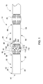
- FIG. 1 is a side view of an exemplary embodiment of a busway electrical distribution system 10.
- Busway electrical distribution system 10 includes a first busway section 12, a second busway section 14, and a third busway section 16.
- First busway section 12 is coupled to second busway section 14 by a first joint 18.
- second busway section 14 is coupled to third busway section 16 by a second joint 20. Joints for coupling busway sections are known in the art.
- First busway section 12 includes multiple components, for example, a first component and a second component.
- a non-limiting example of the first component is a first busway body 22 and a non-limiting example of the second component is a ground conductor or ground busbar 24.
- first busway body 22 includes a first plurality of conductors 32 and a first housing 34.
- the plurality of conductors 32 also referred to herein as busbars, extend from a first end 36 of housing 34 to a second end 38 of housing 34.
- Housing 34 defines an interior 40 of first busway section 12 and an exterior 42 of first busway section 12.
- Interior 40 of a busway section is defined herein as an area within the housing.
- the plurality of conductors 32 are at least partially contained within interior 40 of housing 34.
- ground busbar 24 is coupled to housing 34. Ground busbar 24 facilitates grounding between busway sections, for example, between first busway section 12 and second busway section 14.
- Second busway section 14 also includes multiple components.
- second busway section 14 includes a second busway body 58 and a ground busbar 60.
- second busway body 58 includes a second plurality of conductors 62 and a second housing 64.
- the plurality of conductors 62 also referred to herein as busbars, extend from first end 66 of housing 64 to a second end 68 of housing 64.
- the plurality of conductors 62 are at least partially contained within interior 40 of housing 64.
- ground busbar 60 is coupled to housing 64 and facilitates grounding of busway sections 12 and 14.
- Joint 18 couples first busway section 12 and second busway section 14. More specifically, joint 18 couples first plurality of conductors 32 to second plurality of conductors 62. Joint 18 also couples ground busbar 24 to ground busbar 60, ensuring proper grounding between first busway section 12 and second busway section 14. In an alternative embodiment, a single ground busbar (not shown in Figure 1 ) extends between second end 38 of first housing 34 and first end 66 of second housing 64, and is coupled to first housing 34 and second housing 64.
- the methods and systems described herein facilitate coupling a first component and a second component, for example, ground busbar 24 to first housing 34.
- the methods and systems described herein may also be used to couple other components within busway system 10, such as, but not limited to, joint 18 and first plurality of conductors 32, joint 18 and second plurality of conductors 62, and/or a busway housing to a support structure (e.g., floor, wall, ceiling, and/or hangar).
- a support structure e.g., floor, wall, ceiling, and/or hangar
- FIG. 2 is a perspective view of a portion 88 of busway system 10 (shown in Figure 1 ).
- Figure 3 is a side view of portion 88. Components shown in both Figure 2 and Figure 3 are identified with identical reference numerals.
- busway system 10 includes a fastener sealing system 90.
- fastener sealing system 90 secures a first busway component to a second busway component, for example, ground busbar 60 to second housing 64.
- Housing 64 includes a first panel 92, a second panel 94, a third panel 96, and a fourth panel 98. Although described as including four panels 92, 94, 96, and 98, housing 64 may include any number of panels suitable to define interior 40.
- plurality of conductors 62 includes a first busbar 100, a second busbar 102, a third busbar 104, and a fourth busbar 106 (shown in Figure 1 ).
- First busbar 100 includes a first busbar end 108
- second busbar 102 includes a second busbar end 110
- third busbar 104 includes a third busbar end 112 (shown in Figure 1 )
- fourth busbar 106 includes a fourth busbar end 114 (shown in Figure 1 ).
- plurality of conductors 62 may include any suitable number of busbars that allows system 10 to function as described herein.
- FIG 4 is a cross-sectional view of second busway housing 64, ground busbar 60, and fastener sealing system 90 taken along lines 4-4 (shown in Figure 3 ).
- fastener sealing system 90 includes a fastener 118, a spacing device 120, and a sealing device 130.
- fastener sealing system 90 may include more than one spacing device 120 and/or sealing device 130.
- busway housing 64 includes a first opening 140 defined within first panel 92 by a first edge 142. Opening 140 has an outer diameter 144.
- opening 140 is substantially circular and is centered about a fastener axis 146.
- Ground busbar 60 includes a second opening 150 defined therein by a second edge 152.
- Opening 150 has an outer diameter 154.
- First opening 140 and second opening 150 align to form a fastener opening 156, configured to receive fastener 118.
- fastener 118 is a threaded fastener that includes a restraining portion 158 and a fastener body 160 configured for coupling with a complementary fastening member 162.
- fastener 118 may be a tiebolt configured for coupling with a nut, a threaded opening within a surface, or any other fastening member that allows fastener sealing system 90 to function as described herein.
- a gap 164 is present between an outer surface 166 of fastener 118 and first edge 142 of housing 64. Gap 164 allows fastener 118 to be inserted through opening 140 and may vary depending upon manufacturing tolerances of fastener 118 and/or opening 140 within housing 64.
- sealing is defined as preventing contaminants from entering interior 40 of busway housing 64. Such contaminants typically enter busway housing 64 through spaces around fasteners, for example, gap 164.
- Fastener sealing system 90 is configured to secure ground busbar 60 to second busway body 58 and to prevent contaminants, such as but not limited to, water and dust, from reaching interior 40 of busway housing 64 from exterior 42 of busway housing 64.
- Sealing device 130 seals gap 164 between fastener 118 and opening 140 such that contaminants are prevented from entering housing 64.
- levels of protection provided against intrusion of water and other contaminants are defined in international standards, for example, international standards promulgated by the International Electrotechnical Commission (IEC).
- a busway system installed exterior to a structure may be manufactured to meet an International Protection Rating, also referred to as an IP Code, of IP65.
- IP65 International Protection Rating
- a rating of IP65 is achieved if the seal is "dust tight," that is, the interior is completely protected against contact with dust, and the seal protects the interior from harmful effects caused by water projected in powerful jets against the enclosure from any direction.
- fastener sealing system 90 is not limited to a specific seal rating.
- spacing device 120 includes a compression spacer 170 and a spring washer 172.
- Sealing device 130 includes a gasketed washer 174 that directly contacts an exterior surface 178 of first panel 92 to provide a seal. Although described herein as including a gasketed washer, sealing device 130 may include any type of seal or sealant, for example, but not limited to, a liquid sealant.
- opening 150 extending through ground busbar 60 is configured to receive gasketed washer 174. More specifically, gasketed washer 174 has an outer diameter 180 that is less than diameter 154 of second opening 150. Gasketed washer 174 is positioned within opening 150 such that a radially outward surface 182 of gasketed washer 174 is positioned against edge 152 of ground busbar 60. At least a portion of ground busbar 60 and gasketed washer 174 directly contact housing 64.
- ground busbar 60 includes a projection 184, for example, a half-shear bump, which provides a direct ground path between ground busbar 60 and housing 64.
- compression spacer 170 includes an opening 186 having an inner diameter 188 defined by a first end 190.
- Compression spacer 170 also includes a second end 192 that has an outer diameter 194.
- Compression spacer 170 includes a first notch 196 positioned at first end 190 and configured to receive at least a portion of spring washer 172.
- Compression spacer 170 also includes a second notch 198 positioned at second end 192 and configured to receive at least a portion of ground busbar 60, for example, second edge 152.
- a force applied to fastener 118 during assembly of busway system 10 is applied to ground busbar 60 and to gasketed washer 174 through compression spacer 170.
- a torque applied to a threaded fastener is converted to a compression force.
- the compression force compresses gasketed washer 174 and secures contact between ground busbar 60 and housing 64.
- the compression force is applied to spring washer 172 and gasketed washer 174 is compressed by compression spacer 170 to the greatest extent at first end 190.
- the compression force applied to spring washer 172 is transmitted through compression spacer 170 to ground busbar 60 at second notch 198.
- First notch 196 and second notch 198 are configured to facilitate transferring compression force to properly seal gap 164 and to maintain contact between ground busbar 60 and housing 64.
- compression spacer 170 maintains the compression force on gasketed washer 174 and maintains the ground path between busway housing 64 and ground busbar 60 even when fastener torque has decreased.
- Compression spacer 170 is also utilized to control an amount of compression on gasketed washer 174.
- Spring washer 172 is positioned between compression spacer 170 and restraining portion 158 of fastener 118 to facilitate maintaining torque on fastener 118.
- Gasketed washer 174 is configured to provide an optimum seal at a predefined compression force. This force is applied to gasketed washer 174 during assembly. However, even as torque on fastener 118 decreases over time, gasketed washer 174 maintains the seal. For example, fastener 118 may have an initial torque of fifteen foot-pounds. Unlike other seals, for example, an aluminum washer, gasketed washer 174 maintains the seal even if the torque from fastener 118 is reduced to, for example, three foot-pounds.
- FIG 5 is a flow chart 200 of an exemplary method 210 for coupling a first busway component to a second busway component, for example, ground busbar 60 (shown in Figure 2 ) to housing 64 (shown in Figure 2 ).
- housing 64 includes first opening 140 (shown in Figure 4 ) defined therein and ground busbar 60 includes second opening 150 (shown in Figure 4 ) defined therein.
- method 210 includes configuring 220 ground busbar 60 and housing 64 to align such that first opening 140 and second opening 150 define a single fastener opening, for example, fastener opening 156.
- Configuring 220 further includes configuring ground busbar 60 to contact housing 64, which provides an electrical ground connection therebetween.
- Method 210 further includes configuring 222 a fastener sealing system, for example, fastener sealing system 90 (shown in Figure 2 ) to secure ground busbar 60 to housing 64.
- Fastener sealing system 90 includes a fastener, for example, fastener 118 (shown in Figure 4 ) and at least one seal device, for example, gasketed washer 174 (shown in Figure 4 ).
- Configuring 222 includes configuring fastener 118 to extend through fastener opening 156 and configuring gasketed washer 174 to prevent contaminants from passing through opening 156.
- method 210 may also include configuring 226 at least one spacing device, for example, spacing device 120 (shown in Figure 4 ) for positioning between restraining portion 158 of fastener 118 and gasketed washer 174.
- Fastener 118 is configured to secure ground busbar 60 to housing 64 and compress spacing device 120 and gasketed washer 174.
- Method 210 may also include configuring 228 spacing device 120 to maintain a substantially fixed compression force on gasketed washer 174.
- Described herein are exemplary methods and systems for coupling a first busway component to a second busway component. More specifically, the methods and systems described herein facilitate eliminating leakage in tiebolts closest to the joints while maintaining the necessary ground path contact. Also, by positioning the gasketed washer along a surface of the housing, the gasketed washer permanently deforms to create a seal with the busway housing. Since the gasketed washer rests directly against the busway housing it is able to flow slightly into the tiebolt hole as well as around the tiebolt. This deforms the gasketed washer permanently, which creates a durable seal. Tiebolts tend to lose their torque over time, however, the methods and systems described herein facilitate maintaining the seal even as the torque decreases. The methods and systems described herein also provide a direct ground path connection between a ground busbar and a busway housing.
- the methods and systems described herein facilitate efficient and economical manufacture and assembly of a busway based electrical distribution network. Exemplary embodiments of methods and systems are described and/or illustrated herein in detail. The methods and systems are not limited to the specific embodiments described herein, but rather, components of each system, as well as steps of each method, may be utilized independently and separately from other components and steps described herein. Each component, and each method step, can also be used in combination with other components and/or method steps.
Applications Claiming Priority (1)
| Application Number | Priority Date | Filing Date | Title |
|---|---|---|---|
| US12/960,874 US8785776B2 (en) | 2010-12-06 | 2010-12-06 | Methods and systems for coupling busway components |
Publications (3)
| Publication Number | Publication Date |
|---|---|
| EP2461445A2 true EP2461445A2 (de) | 2012-06-06 |
| EP2461445A3 EP2461445A3 (de) | 2014-02-19 |
| EP2461445B1 EP2461445B1 (de) | 2020-09-02 |
Family
ID=45098920
Family Applications (1)
| Application Number | Title | Priority Date | Filing Date |
|---|---|---|---|
| EP11191455.2A Active EP2461445B1 (de) | 2010-12-06 | 2011-12-01 | Verfahren und Systeme zum Koppeln von Stromschienenkomponenten |
Country Status (5)
| Country | Link |
|---|---|
| US (1) | US8785776B2 (de) |
| EP (1) | EP2461445B1 (de) |
| JP (1) | JP2012124160A (de) |
| KR (1) | KR101816316B1 (de) |
| CN (2) | CN102545118B (de) |
Cited By (1)
| Publication number | Priority date | Publication date | Assignee | Title |
|---|---|---|---|---|
| US20220173584A1 (en) * | 2020-07-06 | 2022-06-02 | Starline Holdings, Llc | Systems and Methods for Dust and Liquid Protected Continuous Access Busway Trunking Systems |
Families Citing this family (7)
| Publication number | Priority date | Publication date | Assignee | Title |
|---|---|---|---|---|
| US8785776B2 (en) * | 2010-12-06 | 2014-07-22 | General Electric Company | Methods and systems for coupling busway components |
| KR101439705B1 (ko) | 2012-12-28 | 2014-09-12 | 대한전선 주식회사 | 부스덕트 도체 접속부에 체결되는 절연팩 블록 |
| KR102439247B1 (ko) * | 2015-09-25 | 2022-08-31 | 엘에스전선 주식회사 | 부스덕트 접속부 및 그 접속방법 |
| CN105449605B (zh) * | 2015-12-23 | 2017-11-14 | 湖北新昇电气有限公司 | 高强度母线桥框架 |
| JP2018116891A (ja) * | 2017-01-20 | 2018-07-26 | 株式会社オートネットワーク技術研究所 | 配線モジュール |
| US20220416351A1 (en) * | 2021-06-28 | 2022-12-29 | Rivian Ip Holdings, Llc | Fasteners and assemblies for servicing high voltage components of a battery system |
| CN117154446A (zh) * | 2023-08-23 | 2023-12-01 | 镇江加勒智慧电力科技股份有限公司 | 一种母线槽单元旋转取电连接器 |
Family Cites Families (11)
| Publication number | Priority date | Publication date | Assignee | Title |
|---|---|---|---|---|
| US3446911A (en) | 1967-04-11 | 1969-05-27 | Square D Co | Bus duct section with ground bus bar |
| US3786394A (en) | 1972-03-22 | 1974-01-15 | Cutler Hammer Inc | Single-bolt joint for feeder and plug-in bus ducts |
| JPH05161236A (ja) * | 1991-12-06 | 1993-06-25 | Hitachi Cable Ltd | 防水形絶縁バスダクト接続部 |
| US5760339A (en) | 1993-03-25 | 1998-06-02 | Siemens Energy & Automation, Inc. | Busway joint |
| US5466889A (en) | 1993-03-25 | 1995-11-14 | Siemens Energy & Automation, Inc. | Electrical power busway and insulator assembly |
| CN2334113Y (zh) * | 1998-04-27 | 1999-08-18 | 上海第四建筑公司武进江南电器公司 | 空气密集型防火母线槽 |
| US7307823B2 (en) * | 2003-05-22 | 2007-12-11 | Eaton Corporation | Modular surge suppressor system and surge suppressor module |
| JP2007278362A (ja) * | 2006-04-05 | 2007-10-25 | Mitsui Home Co Ltd | 防水ワッシャおよびその製造方法 |
| JP4846523B2 (ja) * | 2006-10-26 | 2011-12-28 | 矢崎総業株式会社 | ボルト締結構造 |
| US8378219B2 (en) * | 2009-12-03 | 2013-02-19 | Schneider Electric USA, Inc. | Nesting dielectric insulators |
| US8785776B2 (en) * | 2010-12-06 | 2014-07-22 | General Electric Company | Methods and systems for coupling busway components |
-
2010
- 2010-12-06 US US12/960,874 patent/US8785776B2/en active Active
-
2011
- 2011-12-01 EP EP11191455.2A patent/EP2461445B1/de active Active
- 2011-12-01 JP JP2011263170A patent/JP2012124160A/ja active Pending
- 2011-12-05 KR KR1020110129142A patent/KR101816316B1/ko active IP Right Grant
- 2011-12-06 CN CN201110421063.0A patent/CN102545118B/zh active Active
- 2011-12-06 CN CN2011205762249U patent/CN202633860U/zh not_active Expired - Lifetime
Non-Patent Citations (1)
| Title |
|---|
| None |
Cited By (1)
| Publication number | Priority date | Publication date | Assignee | Title |
|---|---|---|---|---|
| US20220173584A1 (en) * | 2020-07-06 | 2022-06-02 | Starline Holdings, Llc | Systems and Methods for Dust and Liquid Protected Continuous Access Busway Trunking Systems |
Also Published As
| Publication number | Publication date |
|---|---|
| CN102545118B (zh) | 2016-12-21 |
| EP2461445A3 (de) | 2014-02-19 |
| EP2461445B1 (de) | 2020-09-02 |
| US8785776B2 (en) | 2014-07-22 |
| JP2012124160A (ja) | 2012-06-28 |
| KR20120062637A (ko) | 2012-06-14 |
| US20120138331A1 (en) | 2012-06-07 |
| CN102545118A (zh) | 2012-07-04 |
| KR101816316B1 (ko) | 2018-01-08 |
| CN202633860U (zh) | 2012-12-26 |
Similar Documents
| Publication | Publication Date | Title |
|---|---|---|
| US8785776B2 (en) | Methods and systems for coupling busway components | |
| US7862356B1 (en) | Busway water resistant joint pack or plug-in unit joint | |
| US9800030B2 (en) | Conduit receivers | |
| US20130187599A1 (en) | Charging stations for use in charging electrically powered vehicles and related methods | |
| CA2702906C (en) | Integrated insulator seal and shield assemblies | |
| CN111201686B (zh) | 具有加强件的防风雨电气外壳 | |
| US20130045622A1 (en) | Contact region of an electrically conductive member | |
| KR100986678B1 (ko) | 플러그 인 부스 덕트 | |
| EP1571732A1 (de) | Durchführung und gemeinsame Erdung für elektrische Kabel | |
| US20130285329A1 (en) | Conduit clamp | |
| KR20150002120U (ko) | 접지장치 | |
| CA3045499A1 (en) | Press coupler for electrical conduit | |
| US20100200292A1 (en) | Secondary cap | |
| EP2424057B1 (de) | Elektrisches Leitungssystem und Dichtungsvorrichtung dafür | |
| CA2436552A1 (en) | Sealing device | |
| KR101158642B1 (ko) | 플러그 인 버스웨이 | |
| EP3970263A1 (de) | Getriebeeinheit sowie montage einer getriebeeinheit mit klemmenblock | |
| US8366459B2 (en) | Compression style mid-span ground clamp | |
| JP2001280563A (ja) | ガス配管用絶縁継手 | |
| CA3137998A1 (en) | Press fit condulet devices, assemblies systems and methods for electrical raceway fabrication | |
| KR101460298B1 (ko) | 가스 절연 개폐장치의 변류기 고정장치 | |
| JP2016157742A (ja) | ケーブルダクト、静止誘導機器及び系統連系盤 |
Legal Events
| Date | Code | Title | Description |
|---|---|---|---|
| PUAI | Public reference made under article 153(3) epc to a published international application that has entered the european phase |
Free format text: ORIGINAL CODE: 0009012 |
|
| AK | Designated contracting states |
Kind code of ref document: A2 Designated state(s): AL AT BE BG CH CY CZ DE DK EE ES FI FR GB GR HR HU IE IS IT LI LT LU LV MC MK MT NL NO PL PT RO RS SE SI SK SM TR |
|
| AX | Request for extension of the european patent |
Extension state: BA ME |
|
| PUAL | Search report despatched |
Free format text: ORIGINAL CODE: 0009013 |
|
| AK | Designated contracting states |
Kind code of ref document: A3 Designated state(s): AL AT BE BG CH CY CZ DE DK EE ES FI FR GB GR HR HU IE IS IT LI LT LU LV MC MK MT NL NO PL PT RO RS SE SI SK SM TR |
|
| AX | Request for extension of the european patent |
Extension state: BA ME |
|
| RIC1 | Information provided on ipc code assigned before grant |
Ipc: H02G 5/00 20060101AFI20140114BHEP Ipc: H02B 1/16 20060101ALN20140114BHEP |
|
| 17P | Request for examination filed |
Effective date: 20140819 |
|
| RBV | Designated contracting states (corrected) |
Designated state(s): AL AT BE BG CH CY CZ DE DK EE ES FI FR GB GR HR HU IE IS IT LI LT LU LV MC MK MT NL NO PL PT RO RS SE SI SK SM TR |
|
| 17Q | First examination report despatched |
Effective date: 20160816 |
|
| STAA | Information on the status of an ep patent application or granted ep patent |
Free format text: STATUS: EXAMINATION IS IN PROGRESS |
|
| RAP1 | Party data changed (applicant data changed or rights of an application transferred) |
Owner name: ABB SCHWEIZ AG |
|
| RIC1 | Information provided on ipc code assigned before grant |
Ipc: H02B 1/16 20060101ALN20200227BHEP Ipc: H02G 5/00 20060101AFI20200227BHEP |
|
| GRAP | Despatch of communication of intention to grant a patent |
Free format text: ORIGINAL CODE: EPIDOSNIGR1 |
|
| RIC1 | Information provided on ipc code assigned before grant |
Ipc: H02G 5/00 20060101AFI20200303BHEP Ipc: H02B 1/16 20060101ALN20200303BHEP |
|
| STAA | Information on the status of an ep patent application or granted ep patent |
Free format text: STATUS: GRANT OF PATENT IS INTENDED |
|
| INTG | Intention to grant announced |
Effective date: 20200409 |
|
| GRAS | Grant fee paid |
Free format text: ORIGINAL CODE: EPIDOSNIGR3 |
|
| GRAA | (expected) grant |
Free format text: ORIGINAL CODE: 0009210 |
|
| STAA | Information on the status of an ep patent application or granted ep patent |
Free format text: STATUS: THE PATENT HAS BEEN GRANTED |
|
| AK | Designated contracting states |
Kind code of ref document: B1 Designated state(s): AL AT BE BG CH CY CZ DE DK EE ES FI FR GB GR HR HU IE IS IT LI LT LU LV MC MK MT NL NO PL PT RO RS SE SI SK SM TR |
|
| REG | Reference to a national code |
Ref country code: GB Ref legal event code: FG4D |
|
| REG | Reference to a national code |
Ref country code: AT Ref legal event code: REF Ref document number: 1309909 Country of ref document: AT Kind code of ref document: T Effective date: 20200915 Ref country code: CH Ref legal event code: EP |
|
| REG | Reference to a national code |
Ref country code: DE Ref legal event code: R096 Ref document number: 602011068430 Country of ref document: DE |
|
| REG | Reference to a national code |
Ref country code: IE Ref legal event code: FG4D |
|
| REG | Reference to a national code |
Ref country code: FI Ref legal event code: FGE |
|
| REG | Reference to a national code |
Ref country code: LT Ref legal event code: MG4D |
|
| PG25 | Lapsed in a contracting state [announced via postgrant information from national office to epo] |
Ref country code: HR Free format text: LAPSE BECAUSE OF FAILURE TO SUBMIT A TRANSLATION OF THE DESCRIPTION OR TO PAY THE FEE WITHIN THE PRESCRIBED TIME-LIMIT Effective date: 20200902 Ref country code: LT Free format text: LAPSE BECAUSE OF FAILURE TO SUBMIT A TRANSLATION OF THE DESCRIPTION OR TO PAY THE FEE WITHIN THE PRESCRIBED TIME-LIMIT Effective date: 20200902 Ref country code: GR Free format text: LAPSE BECAUSE OF FAILURE TO SUBMIT A TRANSLATION OF THE DESCRIPTION OR TO PAY THE FEE WITHIN THE PRESCRIBED TIME-LIMIT Effective date: 20201203 Ref country code: BG Free format text: LAPSE BECAUSE OF FAILURE TO SUBMIT A TRANSLATION OF THE DESCRIPTION OR TO PAY THE FEE WITHIN THE PRESCRIBED TIME-LIMIT Effective date: 20201202 Ref country code: NO Free format text: LAPSE BECAUSE OF FAILURE TO SUBMIT A TRANSLATION OF THE DESCRIPTION OR TO PAY THE FEE WITHIN THE PRESCRIBED TIME-LIMIT Effective date: 20201202 Ref country code: SE Free format text: LAPSE BECAUSE OF FAILURE TO SUBMIT A TRANSLATION OF THE DESCRIPTION OR TO PAY THE FEE WITHIN THE PRESCRIBED TIME-LIMIT Effective date: 20200902 |
|
| REG | Reference to a national code |
Ref country code: NL Ref legal event code: MP Effective date: 20200902 |
|
| REG | Reference to a national code |
Ref country code: AT Ref legal event code: MK05 Ref document number: 1309909 Country of ref document: AT Kind code of ref document: T Effective date: 20200902 |
|
| PG25 | Lapsed in a contracting state [announced via postgrant information from national office to epo] |
Ref country code: LV Free format text: LAPSE BECAUSE OF FAILURE TO SUBMIT A TRANSLATION OF THE DESCRIPTION OR TO PAY THE FEE WITHIN THE PRESCRIBED TIME-LIMIT Effective date: 20200902 Ref country code: RS Free format text: LAPSE BECAUSE OF FAILURE TO SUBMIT A TRANSLATION OF THE DESCRIPTION OR TO PAY THE FEE WITHIN THE PRESCRIBED TIME-LIMIT Effective date: 20200902 Ref country code: PL Free format text: LAPSE BECAUSE OF FAILURE TO SUBMIT A TRANSLATION OF THE DESCRIPTION OR TO PAY THE FEE WITHIN THE PRESCRIBED TIME-LIMIT Effective date: 20200902 |
|
| PG25 | Lapsed in a contracting state [announced via postgrant information from national office to epo] |
Ref country code: EE Free format text: LAPSE BECAUSE OF FAILURE TO SUBMIT A TRANSLATION OF THE DESCRIPTION OR TO PAY THE FEE WITHIN THE PRESCRIBED TIME-LIMIT Effective date: 20200902 Ref country code: CZ Free format text: LAPSE BECAUSE OF FAILURE TO SUBMIT A TRANSLATION OF THE DESCRIPTION OR TO PAY THE FEE WITHIN THE PRESCRIBED TIME-LIMIT Effective date: 20200902 Ref country code: NL Free format text: LAPSE BECAUSE OF FAILURE TO SUBMIT A TRANSLATION OF THE DESCRIPTION OR TO PAY THE FEE WITHIN THE PRESCRIBED TIME-LIMIT Effective date: 20200902 Ref country code: PT Free format text: LAPSE BECAUSE OF FAILURE TO SUBMIT A TRANSLATION OF THE DESCRIPTION OR TO PAY THE FEE WITHIN THE PRESCRIBED TIME-LIMIT Effective date: 20210104 Ref country code: RO Free format text: LAPSE BECAUSE OF FAILURE TO SUBMIT A TRANSLATION OF THE DESCRIPTION OR TO PAY THE FEE WITHIN THE PRESCRIBED TIME-LIMIT Effective date: 20200902 Ref country code: SM Free format text: LAPSE BECAUSE OF FAILURE TO SUBMIT A TRANSLATION OF THE DESCRIPTION OR TO PAY THE FEE WITHIN THE PRESCRIBED TIME-LIMIT Effective date: 20200902 |
|
| RAP4 | Party data changed (patent owner data changed or rights of a patent transferred) |
Owner name: ABB SCHWEIZ AG |
|
| PG25 | Lapsed in a contracting state [announced via postgrant information from national office to epo] |
Ref country code: AL Free format text: LAPSE BECAUSE OF FAILURE TO SUBMIT A TRANSLATION OF THE DESCRIPTION OR TO PAY THE FEE WITHIN THE PRESCRIBED TIME-LIMIT Effective date: 20200902 Ref country code: AT Free format text: LAPSE BECAUSE OF FAILURE TO SUBMIT A TRANSLATION OF THE DESCRIPTION OR TO PAY THE FEE WITHIN THE PRESCRIBED TIME-LIMIT Effective date: 20200902 Ref country code: IS Free format text: LAPSE BECAUSE OF FAILURE TO SUBMIT A TRANSLATION OF THE DESCRIPTION OR TO PAY THE FEE WITHIN THE PRESCRIBED TIME-LIMIT Effective date: 20210102 Ref country code: ES Free format text: LAPSE BECAUSE OF FAILURE TO SUBMIT A TRANSLATION OF THE DESCRIPTION OR TO PAY THE FEE WITHIN THE PRESCRIBED TIME-LIMIT Effective date: 20200902 |
|
| REG | Reference to a national code |
Ref country code: DE Ref legal event code: R097 Ref document number: 602011068430 Country of ref document: DE |
|
| PG25 | Lapsed in a contracting state [announced via postgrant information from national office to epo] |
Ref country code: SK Free format text: LAPSE BECAUSE OF FAILURE TO SUBMIT A TRANSLATION OF THE DESCRIPTION OR TO PAY THE FEE WITHIN THE PRESCRIBED TIME-LIMIT Effective date: 20200902 |
|
| PLBE | No opposition filed within time limit |
Free format text: ORIGINAL CODE: 0009261 |
|
| STAA | Information on the status of an ep patent application or granted ep patent |
Free format text: STATUS: NO OPPOSITION FILED WITHIN TIME LIMIT |
|
| REG | Reference to a national code |
Ref country code: CH Ref legal event code: PL |
|
| 26N | No opposition filed |
Effective date: 20210603 |
|
| GBPC | Gb: european patent ceased through non-payment of renewal fee |
Effective date: 20201202 |
|
| PG25 | Lapsed in a contracting state [announced via postgrant information from national office to epo] |
Ref country code: SI Free format text: LAPSE BECAUSE OF FAILURE TO SUBMIT A TRANSLATION OF THE DESCRIPTION OR TO PAY THE FEE WITHIN THE PRESCRIBED TIME-LIMIT Effective date: 20200902 Ref country code: MC Free format text: LAPSE BECAUSE OF FAILURE TO SUBMIT A TRANSLATION OF THE DESCRIPTION OR TO PAY THE FEE WITHIN THE PRESCRIBED TIME-LIMIT Effective date: 20200902 Ref country code: DK Free format text: LAPSE BECAUSE OF FAILURE TO SUBMIT A TRANSLATION OF THE DESCRIPTION OR TO PAY THE FEE WITHIN THE PRESCRIBED TIME-LIMIT Effective date: 20200902 |
|
| REG | Reference to a national code |
Ref country code: BE Ref legal event code: MM Effective date: 20201231 |
|
| PG25 | Lapsed in a contracting state [announced via postgrant information from national office to epo] |
Ref country code: IE Free format text: LAPSE BECAUSE OF NON-PAYMENT OF DUE FEES Effective date: 20201201 Ref country code: LU Free format text: LAPSE BECAUSE OF NON-PAYMENT OF DUE FEES Effective date: 20201201 |
|
| PG25 | Lapsed in a contracting state [announced via postgrant information from national office to epo] |
Ref country code: LI Free format text: LAPSE BECAUSE OF NON-PAYMENT OF DUE FEES Effective date: 20201231 Ref country code: GB Free format text: LAPSE BECAUSE OF NON-PAYMENT OF DUE FEES Effective date: 20201202 Ref country code: CH Free format text: LAPSE BECAUSE OF NON-PAYMENT OF DUE FEES Effective date: 20201231 |
|
| PG25 | Lapsed in a contracting state [announced via postgrant information from national office to epo] |
Ref country code: IS Free format text: LAPSE BECAUSE OF FAILURE TO SUBMIT A TRANSLATION OF THE DESCRIPTION OR TO PAY THE FEE WITHIN THE PRESCRIBED TIME-LIMIT Effective date: 20210102 Ref country code: TR Free format text: LAPSE BECAUSE OF FAILURE TO SUBMIT A TRANSLATION OF THE DESCRIPTION OR TO PAY THE FEE WITHIN THE PRESCRIBED TIME-LIMIT Effective date: 20200902 Ref country code: MT Free format text: LAPSE BECAUSE OF FAILURE TO SUBMIT A TRANSLATION OF THE DESCRIPTION OR TO PAY THE FEE WITHIN THE PRESCRIBED TIME-LIMIT Effective date: 20200902 Ref country code: CY Free format text: LAPSE BECAUSE OF FAILURE TO SUBMIT A TRANSLATION OF THE DESCRIPTION OR TO PAY THE FEE WITHIN THE PRESCRIBED TIME-LIMIT Effective date: 20200902 |
|
| PG25 | Lapsed in a contracting state [announced via postgrant information from national office to epo] |
Ref country code: MK Free format text: LAPSE BECAUSE OF FAILURE TO SUBMIT A TRANSLATION OF THE DESCRIPTION OR TO PAY THE FEE WITHIN THE PRESCRIBED TIME-LIMIT Effective date: 20200902 |
|
| PG25 | Lapsed in a contracting state [announced via postgrant information from national office to epo] |
Ref country code: BE Free format text: LAPSE BECAUSE OF NON-PAYMENT OF DUE FEES Effective date: 20201231 |
|
| PGFP | Annual fee paid to national office [announced via postgrant information from national office to epo] |
Ref country code: IT Payment date: 20231228 Year of fee payment: 13 Ref country code: FR Payment date: 20231221 Year of fee payment: 13 Ref country code: FI Payment date: 20231220 Year of fee payment: 13 Ref country code: DE Payment date: 20231214 Year of fee payment: 13 |