EP2460758B1 - Hydraulischer Rotationsantrieb - Google Patents
Hydraulischer Rotationsantrieb Download PDFInfo
- Publication number
- EP2460758B1 EP2460758B1 EP20110009500 EP11009500A EP2460758B1 EP 2460758 B1 EP2460758 B1 EP 2460758B1 EP 20110009500 EP20110009500 EP 20110009500 EP 11009500 A EP11009500 A EP 11009500A EP 2460758 B1 EP2460758 B1 EP 2460758B1
- Authority
- EP
- European Patent Office
- Prior art keywords
- shaft
- rotational drive
- drive according
- contacting device
- sliding contacting
- Prior art date
- Legal status (The legal status is an assumption and is not a legal conclusion. Google has not performed a legal analysis and makes no representation as to the accuracy of the status listed.)
- Active
Links
Images




Classifications
-
- B—PERFORMING OPERATIONS; TRANSPORTING
- B66—HOISTING; LIFTING; HAULING
- B66C—CRANES; LOAD-ENGAGING ELEMENTS OR DEVICES FOR CRANES, CAPSTANS, WINCHES, OR TACKLES
- B66C3/00—Load-engaging elements or devices attached to lifting or lowering gear of cranes or adapted for connection therewith and intended primarily for transmitting lifting forces to loose materials; Grabs
- B66C3/005—Grab supports, e.g. articulations; Oscillation dampers; Orientation
Definitions
- the invention relates to a hydraulic rotary drive for rotating a load-receiving means relative to a crane arm, according to the preamble of claim 1.
- the invention relates to a crane with a rotary drive according to the invention and a harvester with a crane with a rotary drive according to the invention.
- Generic rotational drives such as with an attached gripper as a load-handling device, find application in numerous fields. Often it is the moving load to bulky items such as logs or pipes or the like. Particularly preferred such rotary drives are used in cranes, which are mounted on vehicles such as in Holz meetntern, taken from English also called Harvester. Likewise, such rotary drives are also used stationary, such as in waste incineration plants or in the construction industry.
- the hydraulic rotary drive is operated via a hydraulic device, which usually leads from a crane arm to the rotary drive.
- the object of the invention is to provide an improved hydraulic rotary drive for rotating a lifting device relative to a crane arm, which is characterized by a broader usability.
- the Gleitromeiervoriques is at least partially not disposed outside of the shaft or the shaft bearing and thereby contributes to smaller dimensions of the hydraulic rotary drive, resulting in a more compact design of a hydraulic rotary drive.
- the power supply to Gleitromeiervorides substantially axially in the shaft and / or runs substantially radially in the shaft bearing or vice versa.
- a protective housing for the - preferably axial - power supply and / or the current discharge is provided. Due to the design of a protective housing damage to the power supply during operation can be prevented.
- the current discharge from the Gleitromeiervorraum is formed on the load receiving means facing the end of the rotary drive and leads away laterally from the rotary drive. Due to the lateral routing of the current discharge, this can take place independently of a load-receiving means attached to the first fastening means.
- the Gleitromeiervorraum is formed on the load receiving means facing the end of the shaft. This can be achieved that the Gleitcardiervortechnisch - such as for maintenance purposes - is easily accessible.
- the shaft is designed as a rotor and the shaft bearing as a stator.
- the Gleit.iervorraum has at least one - preferably four - slip ring (s) and at least one - preferably four - sliding contact (s).
- the formation of a Gleit.iervorides with slip ring and sliding contacts is particularly stable and easy to manufacture.
- the - preferably the four - slip ring (s) is (are) attached to a bearing of the protective housing and that the - Preferably, the four - sliding contact (s) is attached to the shaft (are).
- the arrangement of the slip ring on the stationary part of the rotary drive and on the other hand by the arrangement of the sliding contact on the rotating part of the rotary drive lower moving masses can be achieved.
- a connection of the current discharge to the Gleitromeiervorraum is provided, wherein the connection of the current discharge is formed in the recess.
- the direct connection of the current discharge to the Gleitromeiervorides located in the recess also lower moving masses can be achieved because you can do without a plug or the like on the moving part of the rotary drive.
- Protection is also desired for a crane having a hydraulic rotary drive for rotating a load-bearing means relative to a crane arm, wherein a crane arm is connected to the second fastening means of the hydraulic rotary drive.
- FIG. 1 shows the side view of a harvester 100 also known as wood harvesters.
- This harvester 100 has a crane 101.
- the crane 101 has a crane arm 102 to which, via a rotary joint arrangement 103, the load-receiving means 104, in this embodiment a woodworking device for cutting and trimming trees, is fastened.
- the load-receiving means 104 in this embodiment a woodworking device for cutting and trimming trees, is fastened.
- the load receiving means 104 of the hydraulic rotary drive 1 for rotating the load receiving means 104 is arranged relative to the crane arm 102.
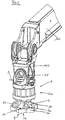
- FIG. 2 shows a crane arm 102, on which a rotary joint assembly 103 is arranged.
- this rotary drive 1 is connected to the crane arm 102.
- the second fastening means 21 are formed as spaced-apart, double tabs, between each of which a crane arm 102 arranged on the counterpart piece can be inserted and rotatably connected by a bolt.
- the rotary joint assembly 103 is formed.
- the rotary joint 103 is formed as a split pivot joint 103, so that there is a free space between the tabs. Of course, this would not have to be this way. Also conceivable would be, for example, a continuous bolt.
- the hydraulic rotary drive 1 has a shaft bearing 20, in whose interior a shaft 10 is formed.
- the shaft 10 has first attachment means 11, via which the load-receiving means 104, not shown, can be fastened to the shaft 10.
- the recess 5, not shown here, and the sliding contacting device 2 arranged therein are formed in this preferred embodiment (see in this regard FIG. 4 and FIG. 5 ).
- FIG. 3 shows a perspective view of a hydraulic rotary drive 1, as just in FIG. 2 described. From this view, it is further clear that the hydraulic connections 51 and 52 are arranged on the shaft 10 for the supply of the load-receiving means 104, not shown. Otherwise, the under FIG. 2 With regard to the rotary drive 1 mentioned.
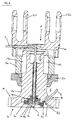
- FIG. 4 shows a hydraulic rotary drive 1 for rotating a load-receiving means 104, not shown here (see FIG. 1 ) relative to a crane arm 102, not shown here (see FIG. 2 ) with a shaft 10 and a shaft bearing 20, first fastening means 11, on the load receiving means 104 facing the end 7 of the shaft 10 for connecting the shaft 10 to the load receiving means 104, and second fastening means 21, which are formed on the shaft bearing 20, for connecting the Shaft bearing 20 with the crane arm 102.
- wings 12 are arranged, which are acted upon to transmit a torque to the shaft 10 via an oil supply and oil removal with oil, as is well known in the art.
- the GleitCountiervorraum 2 is electrically contacted with a power supply 3 and a current drain 4, wherein in this preferred embodiment, the Gleitcardiervorides 2 in the recess 5 of the shaft 10 is substantially completely absorbed.
- the recess 5 is completely encased in this preferred embodiment of the shaft 10 and thus also the Gleitromeiervorides 2 is completely encased by the shaft 10.
- the Gleitromeiervorraum 2 is freely accessible from below, it is also conceivable that you can attach a cover here to close the recess 5 also down.
- the power supply 3 extends in this preferred embodiment, first substantially radially to the shaft bearing 20 and then substantially axially in the shaft 10 to Gleitromeiervorraum 2.
- a protective housing 6 is provided for the axial power supply 3.
- a corresponding protective housing for the radial power supply is possible, but not considered in this embodiment.
- the shaft 10 is in this preferred embodiment on the load receiving means 104 facing the end 7 of the rotary drive 1 on the shaft bearing 20 addition. It can thereby be achieved that the first fastening means 11 are easily accessible in order to establish a connection of the load-receiving means 104 and the shaft 10.
- the load-receiving means 104 is fastened via the fastening means 11 directly below the shaft 10 on the shaft 10.
- the current discharge 4 of the Gleitromeiervoriques is formed in this preferred embodiment of the load receiving means 104 facing the end 7 of the rotary drive 1 and leads of this rotary drive 1 side 8 away.
- the lateral path guide 8 of the current outlet 4 here at an angle of 30 to 60 ° to the longitudinal axis L of the shaft 10.
- the Gleitromeiervorraum 2 is formed on the load receiving means 104 facing the end 7 of the shaft 10, as well as it is of course conceivable - as in the FIG. 6
- the preferred construction is such that the Gleitcardiervoruze 2 at the lower end of the shaft 10th is placed in the recess 5.
- the Gleitcardiervorraum 2 four slip rings 31 and 32 and also corresponding thereto sliding contacts 41 and 42.
- the slip rings 31 and 32 are fixed to a bearing 9 of the protective housing 6 and thus do not rotate with the shaft 10, the sliding contacts 41st and 42 are fixed to the shaft 10 and thus rotate with this. Of course, this could also be done the other way around.
- connection 43 of the current drain 4 takes place here in the interior of the recess 5 of the shaft 10 and not via a connector outside the shaft 10th
- the hydraulic rotary drive 1 is arranged on a crane 101 for rotating the load receiving means 104 relative to the crane arm 102, wherein the crane arm 102 via the second fastening means 21 (see FIG. 2 ) is connected to the hydraulic rotary drive 1.
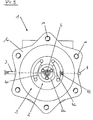
- FIG. 5 shows the bottom view of the hydraulic rotary drive 1, just as in the at FIG. 4 illustrated embodiment.
- FIG. 6 shows an alternative variant for a hydraulic rotary drive 1 for rotating a load-receiving means 104, not shown here relative to a crane arm 102, not shown here, as just in the FIG. 4 and 5 explained.
- the Gleitromeiervorraum 2 is not accessible from the load side medium, but from the crane arm side.
- FIGS. 7 . 8th and 9 will now be discussed in more detail on the drive of the hydraulic rotary drive 1, which is designed for transmitting a torque to the shaft (10) in the interior of the rotary drive 1.
- FIG. 7 shows an exploded perspective view of the hydraulic rotary drive 1 as in the figure description of Figures 2 . 3 . 4 and 5 described. It applies that mentioned there.
- the shaft 10 is formed inside the shaft bearing 20 and inside the stator 50.
- eight wings 12 are formed in this preferred embodiment, as shown in the exploded view of FIG. 8 evident.
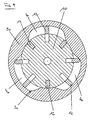
- the wings 12 are spring-loaded (not shown) pushed out of the shaft 10 and extend to the inner wall 30 of the stator 50, wherein the inner wall 30 of the stator 50 has a deviating from the circular cross-section, as shown in the sectional view of FIG. 9 is apparent.
- a preferred guidance of the shaft 10 in the stator ring 50 can be achieved.
- the wings 12 and thus the shaft 10 are driven by oil, which can flow pressurized in the interior 40 between the shaft 10 and the stator ring 50.
Landscapes
- Engineering & Computer Science (AREA)
- Mechanical Engineering (AREA)
- Jib Cranes (AREA)
Description
- Die Erfindung betrifft einen hydraulischen Rotationsantrieb zum Rotieren eines Lastaufnahmemittels relativ zu einem Kranarm, gemäß dem Oberbegriff des Anspruchs 1.
- Weiters betrifft die Erfindung einen Kran mit einem erfindungsgemäßen Rotationsantrieb und einen Harvester mit einem Kran mit einem erfindungsgemäßen Rotationsantrieb.
- Gattungsgemäße Rotationsantriebe, wie zum Beispiel mit einem angebrachten Greifer als Lastaufnahmemittel, finden in zahlreichen Gebieten Anwendung. Oftmals handelt es sich bei dem zu bewegenden Ladegut um sperrige Gegenstände wie Baumstämme oder Rohrleitungen oder Ähnliches. Besonders bevorzugt kommen derartige Rotationsantriebe bei Kränen zum Einsatz, die auf Fahrzeugen montiert sind wie etwa bei Holzvollerntern, aus dem Englischen übernommen auch Harvester genannt. Ebenfalls werden solche Rotationsantriebe auch stationär eingesetzt, wie etwa in Müllverbrennungsanlagen oder in der Bauindustrie. Der hydraulische Rotationsantrieb wird dabei über eine Hydraulikeinrichtung betrieben, die meist von einem Kranarm zum Rotationsantrieb führt.
- So zeigt etwa die
EP 1 889 808 B1 vom 20. Februar 2008 einen Kranarm mit einer Befestigungsvorrichtung für Arbeitsgeräte, wobei die Befestigungsvorrichtung entlang einer vertikalen Achse beabstandete Drehgelenke mit einem kranarmseitigen Drehgelenk und einem arbeitsgeräteseitigen Drehgelenk aufweist, wobei vom Kranarm Schlauchleitungen zu Anschlüssen in einem zwischen Arbeitsgerät und arbeitsgeräteseitigen Drehgelenk angeordneten hydraulischen Rotationsantrieb führen. Dieser Rotationsantrieb ist in seiner Einsetzbarkeit auf solche Lastaufnahmemittel beschränkt, die nicht auf eine elektrische Versorgung angewiesen sind. - Eine solche Vorrichtung ist auch in Dokument
WO 03/057615 A1 - Aufgabe der Erfindung ist es, einen verbesserten hydraulischen Rotationsantrieb zum Rotieren eines Lastaufnahmemittels relativ zu einem Kranarm anzugeben, der sich durch eine breitere Einsetzbarkeit auszeichnet.
- Dies wird durch die Merkmale des Anspruchs 1 gelöst.
- Dies heißt also, dass in der Welle und/oder im Wellenlager eine Ausnehmung vorgesehen ist, in welcher die Gleitkontaktiervorrichtung zumindest teilweise aufgenommen ist. Durch den erfindungsgemäßen hydraulischen Rotationsantrieb sind auch solche Lastaufnahmemittel verwendbar, welche eine elektrische Versorgung benötigen.
- Die Gleitkontaktiervorrichtung ist zumindest teilweise nicht außerhalb der Welle oder dem Wellenlager angeordnet und trägt dadurch zu geringeren Abmessungen des hydraulischen Rotationsantriebes bei, was zu einer kompakteren Bauweise eines hydraulischen Rotationsantriebs führt.
- Ebenfalls wird dadurch erreicht, dass die Gleitkontaktiervorrichtung gegen äußere Krafteinwirkungen geschützt ist, da die Welle oder das Wellenlager die Gleitkontaktiervorrichtung schützend umgibt.
- Weitere vorteilhafte Ausführungen sind in den abhängigen Ansprüchen definiert.
- Als besonders vorteilhaft hat es sich herausgestellt, wenn die Gleitkontaktiervorrichtung im Wesentlichen vollständig in der Ausnehmung aufgenommen ist. Durch das vollständige Einbringen der Gleitkontaktiervorrichtung in die Ausnehmung der Welle oder des Wellenlagers wird eine noch kompaktere Bauweise für einen hydraulischen Rotationsantrieb erzielbar.
- Gemäß einem bevorzugten Ausführungsbeispiel kann vorgesehen sein, dass die Stromzuführung zur Gleitkontaktiervorrichtung im Wesentlichen axial in der Welle verläuft und/oder im Wellenlager im Wesentlichen radial verläuft oder umgekehrt. Dadurch kann eine besonders geschützte Verlegung der Stromzuführung erzielt werden.
- Weiters kann bevorzugt vorgesehen sein, dass ein Schutzgehäuse für die - vorzugsweise axiale - Stromzuführung und/oder die Stromabführung vorgesehen ist. Durch die Ausgestaltung eines Schutzgehäuses kann die Beschädigung der Stromzuführung während des Betriebes verhindert werden.
- Als besonders vorteilhaft hat es sich erwiesen, wenn die Welle an einem dem Lastaufnahmemittel zugewandten Ende des Rotationsantriebs über das Wellenlager vorsteht. Dadurch wird es ermöglicht, dass einerseits das Lastaufnahmemittel auf einfache Art und Weise an einem der Befestigungsmittel befestigt werden kann und andererseits, dass die Stromabführung von der Gleitkontaktiervorrichtung direkt durch die Welle erfolgen kann.
- Besonders bevorzugt kann vorgesehen sein, dass die Stromabführung von der Gleitkontaktiervorrichtung an dem dem Lastaufnahmemittel zugewandten Ende des Rotationsantriebs ausgebildet ist und vom Rotationsantrieb seitlich wegführt. Durch die seitliche Wegführung der Stromabführung kann diese unabhängig von einem an den ersten Befestigungsmitteln befestigten Lastaufnahmemittel erfolgen.
- Als besonders vorteilhaft hat es sich dabei herausgestellt, wenn die seitliche Stromabführung von der Gleitkontaktiervorrichtung im Wesentlichen radial wegführt oder schräg in Richtung des dem Lastaufnahmemittel zugewandten Ende des Rotationsantriebs verläuft.
- Gemäß einem bevorzugten Ausführungsbeispiel kann vorgesehen sein, dass die Gleitkontaktiervorrichtung an dem Lastaufnahmemittel zugewandten Ende der Welle ausgebildet ist. Dadurch kann erzielt werden, dass die Gleitkontaktiervorrichtung - wie etwa für Wartungszwecke - gut zugänglich ist.
- Als vorteilhaft hat es sich weiters herausgestellt, wenn die Welle als Rotor und das Wellenlager als Stator ausgebildet ist.
- Als vorteilhaft hat es sich erwiesen, wenn die Gleitkontaktiervorrichtung mindestens einen - vorzugsweise vier - Schleifring(e) und mindestens einen - vorzugsweise vier - Schleifkontakt(e) aufweist. Die Ausbildung einer Gleitkontaktiervorrichtung mit Schleifring und Schleifkontakten ist besonders stabil und wartungsfreundlich herstellbar.
- Bevorzugt kann weiters vorgesehen sein, dass der - vorzugsweise die vier - Schleifring(e) an einer Lagerung des Schutzgehäuses befestigt ist (sind) und dass der - vorzugsweise die vier - Schleifkontakt(e) an der Welle befestigt ist (sind). Durch die Anordnung des Schleifrings am stehenden Teil des Rotationsantriebs und andererseits durch die Anordnung des Schleifkontakts am rotierenden Teil des Rotationsantriebs können geringer bewegte Massen erzielt werden.
- Gemäß einem möglichen Ausführungsbeispiel kann vorgesehen sein, dass ein Anschluss der Stromabführung an die Gleitkontaktiervorrichtung vorgesehen ist, wobei der Anschluss der Stromabführung in der Ausnehmung ausgebildet ist. Durch den direkten Anschluss der Stromabführung an die in der Ausnehmung befindlichen Gleitkontaktiervorrichtung können ebenfalls geringer bewegte Massen erzielt werden, da man auf einen Stecker oder Ähnliches am bewegten Teil des Rotationsantriebes verzichten kann.
- Schutz wird auch begehrt für einen Kran mit einem hydraulischen Rotationsantrieb zum Rotieren eines Lastaufnahmemittels relativ zu einem Kranarm, wobei ein Kranarm mit dem zweiten Befestigungsmittel des hydraulischen Rotationsantriebes verbunden ist.
- Konkret wird auch Schutz begehrt für einen Harvester mit einem Kran nach Anspruch 13.
- Weitere Einzelheiten und Vorteile der vorliegenden Erfindung werden anhand der Figurenbeschreibung unter Bezugnahme auf die in der Zeichnung dargestellten Ausführungsbeispiele im Folgenden näher erläutert. Darin zeigen:
- Fig. 1
- eine Seitenansicht eines Harvesters
- Fig. 2
- eine perspektivische Ansicht eines hydraulischen Rotationsantriebes an einem Kranarm
- Fig. 3
- eine perspektivische Ansicht eines hydraulischen Rotationsantriebs
- Fig. 4
- ein Schnitt durch eine Vorderansicht eines hydraulischen Rotationsantriebs
- Fig. 5
- eine Untersicht des Rotationsantriebes von
Fig. 4 - Fig.6
- eine Schnitt durch eine Vorderansicht eines weiteren Ausführungsbeispieles eines hydraulischen Rotationsantriebs.
- Fig. 7
- eine perspektivische Explosionsdarstellung eines hydraulischen Rotationsantriebs wie in
Fig. 3 - Fig. 8
- eine perspektivische Explosionsdarstellung einer Welle
- Fig. 9
- eine Schnittdarstellung einer Welle im Wellenlager
-
Figur 1 zeigt die Seitenansicht eines Harvesters 100 auch als Holzvollernter bekannt. Dieser Harvester 100 weist einen Kran 101 auf. Der Kran 101 wiederum hat einen Kranarm 102, an dem über eine Drehgelenksanordnung 103 das Lastaufnahmemittel 104, in diesem Ausführungsbeispiel ein Holzbearbeitungsgerät zum Schneiden und Entasten von Bäumen, befestigt ist. Zwischen der Drehgelenksanordnung 103 und dem Lastaufnahmemittel 104 ist der hydraulische Rotationsantrieb 1 zum Rotieren des Lastaufnahmemittels 104 relativ zum Kranarm 102 angeordnet. -
Figur 2 zeigt einen Kranarm 102, an dem eine Drehgelenksanordnung 103 angeordnet ist. Ober die zweiten Befestigungsmittel 21 des hydraulischen Rotationsantriebs 1 ist dieser Rotationsantrieb 1 mit dem Kranarm 102 verbunden. Hier sind die zweiten Befestigungsmittel 21 als mit Abstand zueinander angeordnete, doppelte Laschen ausgebildet, zwischen denen jeweils ein am Kranarm 102 angeordnetes Gegenstück einführbar und durch einen Bolzen drehbar verbindbar ist. Hierdurch wird die Drehgelenksanordnung 103 gebildet. Im gezeigten Ausführungsbeispiel ist das Drehgelenk 103 als geteiltes Drehgelenk 103 ausgebildet, sodass zwischen den Laschen ein Freiraum besteht. Dies müsste natürlich nicht so sein. Auch vorstellbar wäre zum Beispiel ein durchgehender Bolzen. - Der hydraulische Rotationsantrieb 1 weist ein Wellenlager 20 auf, in dessen Inneren eine Welle 10 ausgebildet ist. Die Welle 10 weist erste Befestigungsmittel 11, über die das nicht dargestellte Lastaufnahmemittel 104 an der Welle 10 befestigt werden kann.
- Im Inneren der Welle 10 ist in diesem bevorzugten Ausführungsbeispiel die hier nicht dargestellte Ausnehmung 5 und die darin angeordnete Gleitkontaktiervorrichtung 2 ausgebildet (siehe dazu
Figur 4 undFigur 5 ). - Zu der hier nicht sichtbaren Gleitkontaktiervorrichtung 2 führt einerseits die Stromzuführung 3 und andererseits die Stromabführung 4 (siehe dazu Figurenbeschreibung der
Figur 4 ). -
Figur 3 zeigt eine perspektivische Darstellung eines hydraulischen Rotationsantriebs 1, wie eben inFigur 2 beschrieben. Aus dieser Ansicht geht weiters gut hervor, dass an der Welle 10 die Hydraulikanschlüsse 51 und 52 zur Versorgung des nicht dargestellten Lastaufnahmemittels 104 angeordnet sind. Ansonsten gilt das unterFigur 2 bezüglich des Rotationsantriebs 1 Erwähnte. -
Figur 4 zeigt einen hydraulischen Rotationsantrieb 1 zum Rotieren eines hier nicht dargestellten Lastaufnahmemittels 104 (sieheFigur 1 ) relativ zu einem hier nicht dargestellten Kranarm 102 (sieheFigur 2 ) mit einer Welle 10 und einem Wellenlager 20, ersten Befestigungsmittel 11, an der dem Lastaufnahmemittel 104 zugewandten Ende 7 der Welle 10 zum Verbinden der Welle 10 mit dem Lastaufnahmemittel 104, und zweiten Befestigungsmittel 21, welche am Wellenlager 20 ausgebildet sind, zum Verbinden des Wellenlagers 20 mit dem Kranarm 102. In der Welle 10 sind Flügel 12 angeordnet, die zur Übertragung eines Drehmoments auf die Welle 10 über eine Ölzufuhr und eine Ölabführung mit Öl beaufschlagbar sind, wie hinreichend aus dem Stande der Technik bekannt. Die Gleitkontaktiervorrichtung 2 ist mit einer Stromzuführung 3 und einer Stromabführung 4 elektrisch kontaktiert, wobei in diesem bevorzugten Ausführungsbeispiel die Gleitkontaktiervorrichtung 2 in der Ausnehmung 5 der Welle 10 im Wesentlichen vollständig aufgenommen ist. - Die Ausnehmung 5 wird in diesem bevorzugten Ausführungsbeispiel völlig von der Welle 10 ummantelt und somit wird auch die Gleitkontaktiervorrichtung 2 vollständig von der Welle 10 ummantelt.
- Zu Wartungszwecken ist die Gleitkontaktiervorrichtung 2 von unten frei zugänglich, ebenso ist es natürlich vorstellbar, dass man hier eine Abdeckung anbringen kann, um die Ausnehmung 5 auch nach unten hin zu verschließen.
- Die Stromzuführung 3 verläuft in diesem bevorzugten Ausführungsbeispiel zuerst im Wesentlichen radial zum Wellenlager 20 und anschließend im Wesentlichen axial in der Welle 10 bis hin zur Gleitkontaktiervorrichtung 2. Bevorzugter Weise ist dabei ein Schutzgehäuse 6 für die axiale Stromzuführung 3 vorgesehen. Ebenso natürlich ist auch ein entsprechendes Schutzgehäuse für die radiale Stromzuführung möglich, in diesem Ausführungsbeispiel aber nicht angedacht.
- Die Welle 10 steht in diesem bevorzugten Ausführungsbeispiel an dem dem Lastaufnahmemittel 104 zugewandten Ende 7 des Rotationsantriebs 1 über das Wellenlager 20 hinaus. Dadurch kann erzielt werden, dass die ersten Befestigungsmittel 11 leicht zugänglich sind, um eine Verbindung des Lastaufnahmemittels 104 und der Welle 10 herzustellen.
- Dabei wird das Lastaufnahmemittel 104 über die Befestigungsmittel 11 unmittelbar unterhalb der Welle 10 an der Welle 10 befestigt.
- Die Stromabführung 4 von der Gleitkontaktiervorrichtung ist in diesem bevorzugten Ausführungsbeispiel an dem dem Lastaufnahmemittel 104 zugewandten Ende 7 des Rotationsantriebs 1 ausgebildet und führt von diesem Rotationsantrieb 1 seitlich 8 weg. Dabei weist die seitliche Wegführung 8 der Stromabführung 4 hier einen Winkel von 30 bis 60° zu der Längsachse L der Welle 10 auf.
- In diesem Ausführungsbeispiel ist die Gleitkontaktiervorrichtung 2 an dem dem Lastaufnahmemittel 104 zugewandten Ende 7 der Welle 10 ausgebildet, ebenso ist es natürlich vorstellbar - wie in der
Figur 6 dargestellt - dass die Gleitkontaktiervorrichtung 2 im Wellenlager 20 ,ausgebildet ist oder an dem dem Kranarm 102 zugewandten Ende der Welle 10. In der Praxis hat es sich jedoch gezeigt, dass die bevorzugte Bauweise so erfolgt, dass die Gleitkontaktiervorrichtung 2 am unteren Ende der Welle 10 in der Ausnehmung 5 platziert wird. In dem in dieserFigur 4 dargestellten Ausführungsbeispiel als auch in dem in derFigur 6 dargestellten Ausführungsbeispiel weist die Gleitkontaktiervorrichtung 2 vier Schleifringe 31 und 32 auf und ebenso damit korrespondierende Schleifkontakte 41 und 42. Dabei sind die Schleifringe 31 und 32 an einer Lagerung 9 des Schutzgehäuses 6 befestigt und drehen sich somit nicht mit der Welle 10 mit, die Schleifkontakte 41 und 42 sind an der Welle 10 befestigt und drehen sich somit mit dieser mit. Dies könnte natürlich auch umgekehrt erfolgen. - Der Anschluss 43 der Stromabführung 4 erfolgt hier im Inneren der Ausnehmung 5 der Welle 10 und nicht über einen Anschlussstecker außen an der Welle 10.
- Besonders bevorzugt kommt der hier dargestellte hydraulische Rotationsantrieb 1 bei einem Holzvollemter 100 - wie in der
Figur 1 dargestellt - zum Einsatz. Dabei wird der hydraulische Rotationsantrieb 1 auf einem Kran 101 zum Rotieren des Lastaufnahmemittels 104 relativ zu dem Kranarm 102 angeordnet, wobei der Kranarm 102 über die zweiten Befestigungsmittel 21 (sieheFigur 2 ) mit dem hydraulischen Rotationsantrieb 1 verbunden ist. -
Figur 5 zeigt die Untersicht des hydraulischen Rotationsantriebs 1, wie eben in dem bei derFigur 4 erläuterten Ausführungsbeispiel. - Aus dieser Ansicht ist gut erkennbar, dass die Gleitkontaktiervorrichtung 2 rundherum von der Welle 10 des Rotationsantriebs 1 umschlossen ist. Dabei ist die Gleitkontaktiervorrichtung 2 und all ihre Bestandteile, wie etwa die Schleifringe 31 und 32 als auch die Schleifkontakte 41 und 42 in der Ausnehmung 5 der Welle 10 angeordnet und werden von der Welle 10 umschlossen und ragen dabei bevorzugter Weise nicht über das untere Ende 7 (siehe
Figur 4 ) der Welle 10 bzw. des Rotationsantriebs 1 hinaus. -
Figur 6 zeigt eine alternative Variante für einen hydraulischen Rotationsantrieb 1 zum Rotieren eines hier nicht dargestellten Lastaufnahmemittels 104 relativ zu einem hier nicht dargestellten Kranarm 102, wie eben in denFigur 4 und5 erläutert. - In dieser Schnittdarstellung ist gut erkennbar, dass sich die Gleitkontaktiervorrichtung 2 zwar ebenfalls in einer Ausnehmung 5 des Rotationsantriebes 1 ausgebildet ist, jedoch ist diese Ausnehmung 5 in dieser Variante nicht in der Welle 10 angeordnet, sondern im Wellenlager 20.
- Somit ist die Gleitkontaktiervorrichtung 2 nicht von der Lastmittelseite her zugänglich, sondern von der Kranarmseite.
- Durch diese Anordnung ergibt sich, dass die Stromzuführung 3 zur Gleitkontaktiervorrichtung 2 radial erfolgt, die Stromabführung 4 hingegen erfolgt in diesem Ausführungsbeispiel zuerst axial geschützt durch eine Schutzgehäuse 6 und anschließend - ebenso wie bei dem Ausführungsbeispiel in
Figur 4 und5 dargestellt - seitlich 8 von der Welle 10 weg. Es wäre natürlich ebenso vorstellbar, dass die Stromabführung 4 nicht seitlich 8, sondern am unteren Ende 7 der Welle 10 erfolgt. Ansonsten gilt auch für dieses Ausführungsbeispiel - wie in derFigur 6 dargestellt - sinngemäß das bezüglich des inFigur 4 dargestellten Ausführungsbeispiels Erwähnte. Anders als inFigur 6 dargestellt, kann die Gleitkontaktiervorrichtung 2 auch noch näher am kranarmseitigen Ende des Rotationsantriebs 1 angeordnet sein, zum Beispiel zwischen den Laschen des geteilt ausgebildeten Drehgelenks 103 (siehe dazu auch die Beschreibung zurFigur 2 ). - In den
Figuren 7 ,8 und9 wird nun näher auf den Antrieb des hydraulischen Rotationsantriebs 1 eingegangen, der zur Übertragung eines Drehmoments auf die Welle (10) im Inneren des Rotationsantriebs 1 ausgebildet ist. -
Figur 7 zeigt eine perspektivische Explosionsdarstellung des hydraulischen Rotationsantriebs 1 wie in der Figurenbeschreibung derFiguren 2 ,3 ,4 und5 beschrieben. Es gilt das dort Erwähnte. - Wie in dieser
Figur 7 gut erkennbar ist, ist die Welle 10 im Inneren des Wellenlagers 20 und im Inneren des Statorrings 50 ausgebildet. An der Welle 10 sind in diesem bevorzugten Ausführungsbeispiel acht Flügel 12 ausgebildet, wie dies aus der Explosionsdarstellung derFigur 8 hervorgeht. - Die Flügel 12 werden federbelastet (nicht dargestellt) aus der Welle 10 hinausgedrückt und erstrecken sich bis zu der Innenwandung 30 des Statorrings 50, wobei die Innenwandung 30 des Statorrings 50 einen von der Kreisform abweichenden Querschnitt aufweist, wie dies aus der Schnittdarstellung der
Figur 9 ersichtlich ist. Durch die federbelastete, axial bewegliche Ausbildung der Flügel 12 wird dadurch eine bevorzugte Führung der Welle 10 in dem Statorring 50 erzielbar. - Angetrieben werden die Flügel 12 und damit die Welle 10 durch Öl, welches im Innenraum 40 zwischen der Welle 10 und dem Statorring 50 druckbeaufschlagt fließen kann.
- Somit wird eine äußerst kompakte Bauweise eines hydraulischen Rotationsantriebes 1 erzielbar.
Claims (14)
- Hydraulischer Rotationsantrieb (1) zum Rotieren eines Lastaufnahmemittels (104) relativ zu einem Kranarm (102), mit- einer Welle (10), welche erste Befestigungsmittel (11) aufweist, zum Verbinden der Welle (10) mit dem Lastaufnahmemittel (104) oder dem Kranarm (102),- einem Wellenlager (20), welches zweite Befestigungsmittel (21) aufweist, zum Verbinden des Wellenlagers (20) mit dem Kranarm (102) oder dem Lastaufnahmemittel (104),- in der Welle (10) angeordnete Flügel (12), die zur Übertragung eines Drehmoments auf die Welle (10) über eine Ölzuführung und eine Ölabführung mit Öl beaufschlagbar sind,- einer Gleitkontaktiervorrichtung (2), die mit einer Stromzuführung (3) und einer Stromabführung (4) elektrisch kontaktiert ist,dadurch gekennzeichnet, dass in der Welle (10) und/oder im Wellenlager (20) eine Ausnehmung (5) vorgesehen ist, in welcher die Gleitkontaktiervorrichtung (2) zumindest teilweise aufgenommen ist
- Rotationsantrieb nach Anspruch 1, dadurch gekennzeichnet, dass die Gleitkontaktiervorrichtung (2) im Wesentlichen vollständig in der Ausnehmung (5) aufgenommen ist.
- Rotationsantrieb nach Anspruch 1 oder 2, dadurch gekennzeichnet, dass die Stromzuführung (3) zur Gleitkontaktiervorrichtung (2) im Wesentlichen axial in der Welle (10) verläuft und/oder im Wellenlager (20) im Wesentlichen radial verläuft oder umgekehrt.
- Rotationsantrieb nach einem der Ansprüche 1 bis 3, dadurch gekennzeichnet, dass ein Schutzgehäuse (6) für die - vorzugsweise axiale - Stromzuführung (3) und/oder die Stromabführung (4) vorgesehen ist.
- Rotationsantrieb nach einem der Ansprüche 1 bis 4, dadurch gekennzeichnet, dass die Welle (10) an einem dem Lastaufnahmemittel (104) zugewandten Ende (7) des Rotationsantriebs (1) über das Wellenlager (20) vorsteht.
- Rotationsantrieb nach einem der Ansprüche 1 bis 5, dadurch gekennzeichnet, dass die Stromabführung (4) von der Gleitkontaktiervorrichtung (2) an dem dem Lastaufnahmemittel (104) zugewandten Ende des Rotationsantriebs (1) ausgebildet ist und vorzugsweise vom Rotationsantrieb (1) seitlich (8) wegführt.
- Rotationsantrieb nach Anspruch 6, dadurch gekennzeichnet, dass die seitliche (8) Stromabführung (4) von der Gleitkontaktiervorrichtung (2) im Wesentlichen radial wegführt oder schräg In Richtung des dem Lastaufnahmemittel (104) zugewandten Ende des Rotationsantriebs (1) verläuft.
- Rotationsantrieb nach einem der Ansprüche 1 bis 7, dadurch gekennzeichnet, dass die Gleitkontaktiervorrichtung (2) an dem Lastaufnahmemittel (104) zugewandten Ende (7) der Welle (10) ausgebildet ist.
- Rotationsantrieb nach einem der Ansprüche 1 bis 8, dadurch gekennzeichnet, dass die Welle (10) als Rotor und das Wellenlager (20) als Stator ausgebildet ist.
- Rotationsantrieb nach einem der Ansprüche 1 bis 9, dadurch gekennzeichnet, dass die Gleitkontaktiervorrichtung (2) mindestens einen - vorzugsweise vier - Schleifring(e) (31, 32) und mindestens einen - vorzugsweise vier - Schleifkontakt(e) (41, 42) aufweist.
- Rotalionsantrieb nach Anspruch 10, dadurch gekennzeichnet, dass der - vorzugsweise die vier - Schleifring(e) (31, 32) an einer Lagerung (9) des Schutzgehäuse (6) befestigt ist(sind) und dass der - vorzugsweise die vier - Schleifkontakt(e) (41, 42) an der Welle (10) befestigt ist(sind).
- Rotationsantrieb einem der Ansprüche 1 bis 11, gekennzeichnet, dass ein Anschluss (43) der Stromabführung (4) an die Gleitkontaktiervorrichtung (2) vorgesehen ist, wobei der Anschluss (43) der Stromabführung (4) in der Ausnehmung (5) ausgebildet ist.
- Kran (101) mit einem hydraulischen Rotationsantrieb (1) zum Rotieren eines Lastaufnahmemittels (104) relativ zu einem Kranarm (102) nach einem der Ansprüche 1 bis 12, wobei der Kranarm (102) mit dem zweiten Befestigungsmittel (21) des hydraulischen Rotationsantriebs (1) verbunden ist.
- Harvester (100) mit einem Kran (101) nach Anspruch 13.
Applications Claiming Priority (1)
| Application Number | Priority Date | Filing Date | Title |
|---|---|---|---|
| AT20112010A AT510764A1 (de) | 2010-12-02 | 2010-12-02 | Hydraulischer rotationsantrieb |
Publications (2)
| Publication Number | Publication Date |
|---|---|
| EP2460758A1 EP2460758A1 (de) | 2012-06-06 |
| EP2460758B1 true EP2460758B1 (de) | 2014-02-12 |
Family
ID=45318762
Family Applications (1)
| Application Number | Title | Priority Date | Filing Date |
|---|---|---|---|
| EP20110009500 Active EP2460758B1 (de) | 2010-12-02 | 2011-12-01 | Hydraulischer Rotationsantrieb |
Country Status (2)
| Country | Link |
|---|---|
| EP (1) | EP2460758B1 (de) |
| AT (1) | AT510764A1 (de) |
Cited By (1)
| Publication number | Priority date | Publication date | Assignee | Title |
|---|---|---|---|---|
| EP3388385B1 (de) | 2017-04-12 | 2021-09-08 | EPSILON Kran GmbH. | Rotationsantrieb |
Families Citing this family (5)
| Publication number | Priority date | Publication date | Assignee | Title |
|---|---|---|---|---|
| FI127285B (fi) | 2016-05-25 | 2018-03-15 | Ponsse Oyj | Pyörityslaitteen rakenne sekä vastaava pyörityslaite ja metsäkone |
| SE541642C2 (en) * | 2016-08-26 | 2019-11-19 | Indexator Rotator Sys Ab | Rotator arrangement with hydraulic coupling through rotor |
| SE541516C2 (en) * | 2016-08-26 | 2019-10-22 | Indexator Rotator Sys Ab | Rotator arrangement with bearing for axial load distribution |
| SE1850692A1 (en) * | 2018-06-08 | 2019-12-09 | Indexator Rotator Sys Ab | Hydraulic rotator aparatus |
| BR112023000011A2 (pt) * | 2020-07-03 | 2023-01-31 | Indexator Rotator Sys Ab | Rotator para uma ferramenta |
Family Cites Families (3)
| Publication number | Priority date | Publication date | Assignee | Title |
|---|---|---|---|---|
| SE520498E8 (sv) * | 2001-11-26 | 2015-10-20 | Komatsu Forest Ab | Anordning för upphängning av ett vridbart arbetsredskap |
| ATE442339T1 (de) * | 2006-04-03 | 2009-09-15 | Epsilon Kran Gmbh | Kranarm mit einer befestigungsvorrichtung für arbeitsgeräte |
| US7735530B1 (en) * | 2006-10-20 | 2010-06-15 | Puma, Llc | Rotary dangle head having continuous rotation |
-
2010
- 2010-12-02 AT AT20112010A patent/AT510764A1/de not_active Application Discontinuation
-
2011
- 2011-12-01 EP EP20110009500 patent/EP2460758B1/de active Active
Cited By (1)
| Publication number | Priority date | Publication date | Assignee | Title |
|---|---|---|---|---|
| EP3388385B1 (de) | 2017-04-12 | 2021-09-08 | EPSILON Kran GmbH. | Rotationsantrieb |
Also Published As
| Publication number | Publication date |
|---|---|
| EP2460758A1 (de) | 2012-06-06 |
| AT510764A1 (de) | 2012-06-15 |
Similar Documents
| Publication | Publication Date | Title |
|---|---|---|
| EP2460758A1 (de) | Hydraulischer Rotationsantrieb | |
| EP2139654B1 (de) | Motorisch angetriebene werkzeugmaschine | |
| EP1889808B1 (de) | Kranarm mit einer Befestigungsvorrichtung für Arbeitsgeräte | |
| WO2015144613A1 (de) | Roboterarm und montageset | |
| WO2011128427A2 (de) | Drehvorrichtung für ein anbaugerät an einer arbeitsmaschine | |
| EP2964853A1 (de) | Arbeitsgerät mit stationärmast und drehkopf | |
| DE202014105072U1 (de) | Hilfshandgriff und damit ausgestattetes Elektrowerkzeug | |
| DE102016212008A1 (de) | Schleifringsystem und Elektromaschine mit solch einem Schleifringsystem | |
| DE202017007033U1 (de) | Struktur einer Drehvorrichtung und eine entsprechende Drehvorrichtung sowie eine Forstmaschine | |
| DE102004063723B4 (de) | Schutzschild für ein Schneidwerkzeug eines Freischneiders | |
| EP2252431B1 (de) | Handwerkzeugmaschine, insbesondere handgeführte schleifmaschine | |
| EP2135333B1 (de) | Verlängerungskabel für elektrische rohrbearbeitungsvorrichtungen | |
| EP3964650B1 (de) | Schnellwechselsystem zum wechseln von anbaugeräten an einer baumaschine | |
| EP1666671A1 (de) | Schlitzwandfräse | |
| WO2006097092A1 (de) | Drehkolbenmaschine | |
| EP3388385B1 (de) | Rotationsantrieb | |
| DE2214666A1 (de) | Elektrisches Werkzeug | |
| DE10261025A1 (de) | Elektrowerkzeugmaschine mit mehreren, in getrennten Gehäusen untergebrachten Funktionsbaugruppen | |
| DE102005063016A1 (de) | Handwerkzeugmaschine mit Drehgriffverstelleinrichtung | |
| EP1382796A2 (de) | Hydraulischer Drehmotor mit Kabeldurchführung und Fahrzeug mit einem derartigen Drehmotor | |
| DE2202340A1 (de) | Dynamoelektrische Maschine | |
| DE202009002205U9 (de) | Astsäge | |
| DE1935432A1 (de) | Greifvorrichtung fuer Langholz od.dgl. | |
| EP1287952A1 (de) | Drehdurchführung endseitig eines Roboterarms | |
| DE3818177B4 (de) | Drehvorrichtung für hängende Lasten |
Legal Events
| Date | Code | Title | Description |
|---|---|---|---|
| PUAI | Public reference made under article 153(3) epc to a published international application that has entered the european phase |
Free format text: ORIGINAL CODE: 0009012 |
|
| AK | Designated contracting states |
Kind code of ref document: A1 Designated state(s): AL AT BE BG CH CY CZ DE DK EE ES FI FR GB GR HR HU IE IS IT LI LT LU LV MC MK MT NL NO PL PT RO RS SE SI SK SM TR |
|
| AX | Request for extension of the european patent |
Extension state: BA ME |
|
| 17P | Request for examination filed |
Effective date: 20121126 |
|
| RIC1 | Information provided on ipc code assigned before grant |
Ipc: B66C 3/00 20060101AFI20130507BHEP |
|
| GRAP | Despatch of communication of intention to grant a patent |
Free format text: ORIGINAL CODE: EPIDOSNIGR1 |
|
| INTG | Intention to grant announced |
Effective date: 20131014 |
|
| GRAS | Grant fee paid |
Free format text: ORIGINAL CODE: EPIDOSNIGR3 |
|
| GRAA | (expected) grant |
Free format text: ORIGINAL CODE: 0009210 |
|
| AK | Designated contracting states |
Kind code of ref document: B1 Designated state(s): AL AT BE BG CH CY CZ DE DK EE ES FI FR GB GR HR HU IE IS IT LI LT LU LV MC MK MT NL NO PL PT RO RS SE SI SK SM TR |
|
| REG | Reference to a national code |
Ref country code: GB Ref legal event code: FG4D Free format text: NOT ENGLISH |
|
| REG | Reference to a national code |
Ref country code: CH Ref legal event code: EP |
|
| REG | Reference to a national code |
Ref country code: AT Ref legal event code: REF Ref document number: 652059 Country of ref document: AT Kind code of ref document: T Effective date: 20140215 |
|
| REG | Reference to a national code |
Ref country code: IE Ref legal event code: FG4D Free format text: LANGUAGE OF EP DOCUMENT: GERMAN |
|
| REG | Reference to a national code |
Ref country code: DE Ref legal event code: R096 Ref document number: 502011002132 Country of ref document: DE Effective date: 20140327 |
|
| REG | Reference to a national code |
Ref country code: SE Ref legal event code: TRGR |
|
| REG | Reference to a national code |
Ref country code: NL Ref legal event code: VDEP Effective date: 20140212 |
|
| REG | Reference to a national code |
Ref country code: LT Ref legal event code: MG4D |
|
| PG25 | Lapsed in a contracting state [announced via postgrant information from national office to epo] |
Ref country code: NO Free format text: LAPSE BECAUSE OF FAILURE TO SUBMIT A TRANSLATION OF THE DESCRIPTION OR TO PAY THE FEE WITHIN THE PRESCRIBED TIME-LIMIT Effective date: 20140512 Ref country code: LT Free format text: LAPSE BECAUSE OF FAILURE TO SUBMIT A TRANSLATION OF THE DESCRIPTION OR TO PAY THE FEE WITHIN THE PRESCRIBED TIME-LIMIT Effective date: 20140212 Ref country code: IS Free format text: LAPSE BECAUSE OF FAILURE TO SUBMIT A TRANSLATION OF THE DESCRIPTION OR TO PAY THE FEE WITHIN THE PRESCRIBED TIME-LIMIT Effective date: 20140612 |
|
| PG25 | Lapsed in a contracting state [announced via postgrant information from national office to epo] |
Ref country code: ES Free format text: LAPSE BECAUSE OF FAILURE TO SUBMIT A TRANSLATION OF THE DESCRIPTION OR TO PAY THE FEE WITHIN THE PRESCRIBED TIME-LIMIT Effective date: 20140212 Ref country code: NL Free format text: LAPSE BECAUSE OF FAILURE TO SUBMIT A TRANSLATION OF THE DESCRIPTION OR TO PAY THE FEE WITHIN THE PRESCRIBED TIME-LIMIT Effective date: 20140212 Ref country code: CY Free format text: LAPSE BECAUSE OF FAILURE TO SUBMIT A TRANSLATION OF THE DESCRIPTION OR TO PAY THE FEE WITHIN THE PRESCRIBED TIME-LIMIT Effective date: 20140212 Ref country code: PT Free format text: LAPSE BECAUSE OF FAILURE TO SUBMIT A TRANSLATION OF THE DESCRIPTION OR TO PAY THE FEE WITHIN THE PRESCRIBED TIME-LIMIT Effective date: 20140612 |
|
| PG25 | Lapsed in a contracting state [announced via postgrant information from national office to epo] |
Ref country code: RS Free format text: LAPSE BECAUSE OF FAILURE TO SUBMIT A TRANSLATION OF THE DESCRIPTION OR TO PAY THE FEE WITHIN THE PRESCRIBED TIME-LIMIT Effective date: 20140212 Ref country code: LV Free format text: LAPSE BECAUSE OF FAILURE TO SUBMIT A TRANSLATION OF THE DESCRIPTION OR TO PAY THE FEE WITHIN THE PRESCRIBED TIME-LIMIT Effective date: 20140212 Ref country code: HR Free format text: LAPSE BECAUSE OF FAILURE TO SUBMIT A TRANSLATION OF THE DESCRIPTION OR TO PAY THE FEE WITHIN THE PRESCRIBED TIME-LIMIT Effective date: 20140212 |
|
| PG25 | Lapsed in a contracting state [announced via postgrant information from national office to epo] |
Ref country code: RO Free format text: LAPSE BECAUSE OF FAILURE TO SUBMIT A TRANSLATION OF THE DESCRIPTION OR TO PAY THE FEE WITHIN THE PRESCRIBED TIME-LIMIT Effective date: 20140212 Ref country code: EE Free format text: LAPSE BECAUSE OF FAILURE TO SUBMIT A TRANSLATION OF THE DESCRIPTION OR TO PAY THE FEE WITHIN THE PRESCRIBED TIME-LIMIT Effective date: 20140212 Ref country code: CZ Free format text: LAPSE BECAUSE OF FAILURE TO SUBMIT A TRANSLATION OF THE DESCRIPTION OR TO PAY THE FEE WITHIN THE PRESCRIBED TIME-LIMIT Effective date: 20140212 Ref country code: DK Free format text: LAPSE BECAUSE OF FAILURE TO SUBMIT A TRANSLATION OF THE DESCRIPTION OR TO PAY THE FEE WITHIN THE PRESCRIBED TIME-LIMIT Effective date: 20140212 |
|
| REG | Reference to a national code |
Ref country code: DE Ref legal event code: R097 Ref document number: 502011002132 Country of ref document: DE |
|
| PG25 | Lapsed in a contracting state [announced via postgrant information from national office to epo] |
Ref country code: SK Free format text: LAPSE BECAUSE OF FAILURE TO SUBMIT A TRANSLATION OF THE DESCRIPTION OR TO PAY THE FEE WITHIN THE PRESCRIBED TIME-LIMIT Effective date: 20140212 Ref country code: PL Free format text: LAPSE BECAUSE OF FAILURE TO SUBMIT A TRANSLATION OF THE DESCRIPTION OR TO PAY THE FEE WITHIN THE PRESCRIBED TIME-LIMIT Effective date: 20140212 |
|
| PLBE | No opposition filed within time limit |
Free format text: ORIGINAL CODE: 0009261 |
|
| STAA | Information on the status of an ep patent application or granted ep patent |
Free format text: STATUS: NO OPPOSITION FILED WITHIN TIME LIMIT |
|
| 26N | No opposition filed |
Effective date: 20141113 |
|
| REG | Reference to a national code |
Ref country code: DE Ref legal event code: R097 Ref document number: 502011002132 Country of ref document: DE Effective date: 20141113 |
|
| PG25 | Lapsed in a contracting state [announced via postgrant information from national office to epo] |
Ref country code: IT Free format text: LAPSE BECAUSE OF FAILURE TO SUBMIT A TRANSLATION OF THE DESCRIPTION OR TO PAY THE FEE WITHIN THE PRESCRIBED TIME-LIMIT Effective date: 20140212 |
|
| PG25 | Lapsed in a contracting state [announced via postgrant information from national office to epo] |
Ref country code: SI Free format text: LAPSE BECAUSE OF FAILURE TO SUBMIT A TRANSLATION OF THE DESCRIPTION OR TO PAY THE FEE WITHIN THE PRESCRIBED TIME-LIMIT Effective date: 20140212 |
|
| PGFP | Annual fee paid to national office [announced via postgrant information from national office to epo] |
Ref country code: FR Payment date: 20141231 Year of fee payment: 4 |
|
| PG25 | Lapsed in a contracting state [announced via postgrant information from national office to epo] |
Ref country code: BE Free format text: LAPSE BECAUSE OF NON-PAYMENT OF DUE FEES Effective date: 20141231 |
|
| PG25 | Lapsed in a contracting state [announced via postgrant information from national office to epo] |
Ref country code: LU Free format text: LAPSE BECAUSE OF FAILURE TO SUBMIT A TRANSLATION OF THE DESCRIPTION OR TO PAY THE FEE WITHIN THE PRESCRIBED TIME-LIMIT Effective date: 20141201 |
|
| REG | Reference to a national code |
Ref country code: CH Ref legal event code: PL |
|
| REG | Reference to a national code |
Ref country code: IE Ref legal event code: MM4A |
|
| PG25 | Lapsed in a contracting state [announced via postgrant information from national office to epo] |
Ref country code: IE Free format text: LAPSE BECAUSE OF NON-PAYMENT OF DUE FEES Effective date: 20141201 Ref country code: CH Free format text: LAPSE BECAUSE OF NON-PAYMENT OF DUE FEES Effective date: 20141231 Ref country code: LI Free format text: LAPSE BECAUSE OF NON-PAYMENT OF DUE FEES Effective date: 20141231 |
|
| PG25 | Lapsed in a contracting state [announced via postgrant information from national office to epo] |
Ref country code: SM Free format text: LAPSE BECAUSE OF FAILURE TO SUBMIT A TRANSLATION OF THE DESCRIPTION OR TO PAY THE FEE WITHIN THE PRESCRIBED TIME-LIMIT Effective date: 20140212 |
|
| PG25 | Lapsed in a contracting state [announced via postgrant information from national office to epo] |
Ref country code: MC Free format text: LAPSE BECAUSE OF FAILURE TO SUBMIT A TRANSLATION OF THE DESCRIPTION OR TO PAY THE FEE WITHIN THE PRESCRIBED TIME-LIMIT Effective date: 20140212 |
|
| PG25 | Lapsed in a contracting state [announced via postgrant information from national office to epo] |
Ref country code: GR Free format text: LAPSE BECAUSE OF FAILURE TO SUBMIT A TRANSLATION OF THE DESCRIPTION OR TO PAY THE FEE WITHIN THE PRESCRIBED TIME-LIMIT Effective date: 20140513 Ref country code: BG Free format text: LAPSE BECAUSE OF FAILURE TO SUBMIT A TRANSLATION OF THE DESCRIPTION OR TO PAY THE FEE WITHIN THE PRESCRIBED TIME-LIMIT Effective date: 20140212 |
|
| PG25 | Lapsed in a contracting state [announced via postgrant information from national office to epo] |
Ref country code: HU Free format text: LAPSE BECAUSE OF FAILURE TO SUBMIT A TRANSLATION OF THE DESCRIPTION OR TO PAY THE FEE WITHIN THE PRESCRIBED TIME-LIMIT; INVALID AB INITIO Effective date: 20111201 Ref country code: TR Free format text: LAPSE BECAUSE OF FAILURE TO SUBMIT A TRANSLATION OF THE DESCRIPTION OR TO PAY THE FEE WITHIN THE PRESCRIBED TIME-LIMIT Effective date: 20140212 Ref country code: MT Free format text: LAPSE BECAUSE OF FAILURE TO SUBMIT A TRANSLATION OF THE DESCRIPTION OR TO PAY THE FEE WITHIN THE PRESCRIBED TIME-LIMIT Effective date: 20140212 |
|
| GBPC | Gb: european patent ceased through non-payment of renewal fee |
Effective date: 20151201 |
|
| REG | Reference to a national code |
Ref country code: FR Ref legal event code: ST Effective date: 20160831 |
|
| PG25 | Lapsed in a contracting state [announced via postgrant information from national office to epo] |
Ref country code: GB Free format text: LAPSE BECAUSE OF NON-PAYMENT OF DUE FEES Effective date: 20151201 |
|
| PG25 | Lapsed in a contracting state [announced via postgrant information from national office to epo] |
Ref country code: FR Free format text: LAPSE BECAUSE OF NON-PAYMENT OF DUE FEES Effective date: 20151231 |
|
| REG | Reference to a national code |
Ref country code: AT Ref legal event code: MM01 Ref document number: 652059 Country of ref document: AT Kind code of ref document: T Effective date: 20161201 |
|
| PG25 | Lapsed in a contracting state [announced via postgrant information from national office to epo] |
Ref country code: AT Free format text: LAPSE BECAUSE OF NON-PAYMENT OF DUE FEES Effective date: 20161201 |
|
| PG25 | Lapsed in a contracting state [announced via postgrant information from national office to epo] |
Ref country code: MK Free format text: LAPSE BECAUSE OF FAILURE TO SUBMIT A TRANSLATION OF THE DESCRIPTION OR TO PAY THE FEE WITHIN THE PRESCRIBED TIME-LIMIT Effective date: 20140212 |
|
| PG25 | Lapsed in a contracting state [announced via postgrant information from national office to epo] |
Ref country code: AL Free format text: LAPSE BECAUSE OF FAILURE TO SUBMIT A TRANSLATION OF THE DESCRIPTION OR TO PAY THE FEE WITHIN THE PRESCRIBED TIME-LIMIT Effective date: 20140212 |
|
| P01 | Opt-out of the competence of the unified patent court (upc) registered |
Effective date: 20230601 |
|
| PGFP | Annual fee paid to national office [announced via postgrant information from national office to epo] |
Ref country code: FI Payment date: 20251222 Year of fee payment: 15 |
|
| PGFP | Annual fee paid to national office [announced via postgrant information from national office to epo] |
Ref country code: SE Payment date: 20251222 Year of fee payment: 15 |
|
| PGFP | Annual fee paid to national office [announced via postgrant information from national office to epo] |
Ref country code: DE Payment date: 20251229 Year of fee payment: 15 |