EP2460679A1 - Elektrisches Hybridfahrzeug und Steuerverfahren dafür - Google Patents
Elektrisches Hybridfahrzeug und Steuerverfahren dafür Download PDFInfo
- Publication number
- EP2460679A1 EP2460679A1 EP11191682A EP11191682A EP2460679A1 EP 2460679 A1 EP2460679 A1 EP 2460679A1 EP 11191682 A EP11191682 A EP 11191682A EP 11191682 A EP11191682 A EP 11191682A EP 2460679 A1 EP2460679 A1 EP 2460679A1
- Authority
- EP
- European Patent Office
- Prior art keywords
- actuator
- fuel burning
- amount
- operable
- engine
- Prior art date
- Legal status (The legal status is an assumption and is not a legal conclusion. Google has not performed a legal analysis and makes no representation as to the accuracy of the status listed.)
- Withdrawn
Links
- 238000000034 method Methods 0.000 title claims description 19
- 239000000446 fuel Substances 0.000 claims abstract description 101
- 230000001172 regenerating effect Effects 0.000 claims abstract description 68
- 238000004146 energy storage Methods 0.000 claims abstract description 44
- 238000002485 combustion reaction Methods 0.000 claims description 12
- 239000012530 fluid Substances 0.000 claims description 9
- 230000003137 locomotive effect Effects 0.000 claims description 4
- 230000001419 dependent effect Effects 0.000 claims 1
- 239000007789 gas Substances 0.000 description 34
- 230000008901 benefit Effects 0.000 description 15
- 230000008569 process Effects 0.000 description 6
- 230000000979 retarding effect Effects 0.000 description 4
- 230000005540 biological transmission Effects 0.000 description 3
- 238000011144 upstream manufacturing Methods 0.000 description 3
- CURLTUGMZLYLDI-UHFFFAOYSA-N Carbon dioxide Chemical compound O=C=O CURLTUGMZLYLDI-UHFFFAOYSA-N 0.000 description 2
- 238000001816 cooling Methods 0.000 description 2
- 230000007423 decrease Effects 0.000 description 2
- 230000000994 depressogenic effect Effects 0.000 description 2
- 230000000694 effects Effects 0.000 description 2
- 230000009467 reduction Effects 0.000 description 2
- 230000004044 response Effects 0.000 description 2
- 230000001133 acceleration Effects 0.000 description 1
- 230000009471 action Effects 0.000 description 1
- 239000000654 additive Substances 0.000 description 1
- 229910002092 carbon dioxide Inorganic materials 0.000 description 1
- 239000001569 carbon dioxide Substances 0.000 description 1
- 239000000567 combustion gas Substances 0.000 description 1
- 238000005516 engineering process Methods 0.000 description 1
- 230000017525 heat dissipation Effects 0.000 description 1
- 230000006872 improvement Effects 0.000 description 1
- 230000001151 other effect Effects 0.000 description 1
- 238000010248 power generation Methods 0.000 description 1
- 238000009987 spinning Methods 0.000 description 1
- 239000007858 starting material Substances 0.000 description 1
- 239000013589 supplement Substances 0.000 description 1
- XLYOFNOQVPJJNP-UHFFFAOYSA-N water Substances O XLYOFNOQVPJJNP-UHFFFAOYSA-N 0.000 description 1
Images

Classifications
-
- B—PERFORMING OPERATIONS; TRANSPORTING
- B60—VEHICLES IN GENERAL
- B60W—CONJOINT CONTROL OF VEHICLE SUB-UNITS OF DIFFERENT TYPE OR DIFFERENT FUNCTION; CONTROL SYSTEMS SPECIALLY ADAPTED FOR HYBRID VEHICLES; ROAD VEHICLE DRIVE CONTROL SYSTEMS FOR PURPOSES NOT RELATED TO THE CONTROL OF A PARTICULAR SUB-UNIT
- B60W20/00—Control systems specially adapted for hybrid vehicles
- B60W20/10—Controlling the power contribution of each of the prime movers to meet required power demand
- B60W20/13—Controlling the power contribution of each of the prime movers to meet required power demand in order to stay within battery power input or output limits; in order to prevent overcharging or battery depletion
-
- B—PERFORMING OPERATIONS; TRANSPORTING
- B60—VEHICLES IN GENERAL
- B60K—ARRANGEMENT OR MOUNTING OF PROPULSION UNITS OR OF TRANSMISSIONS IN VEHICLES; ARRANGEMENT OR MOUNTING OF PLURAL DIVERSE PRIME-MOVERS IN VEHICLES; AUXILIARY DRIVES FOR VEHICLES; INSTRUMENTATION OR DASHBOARDS FOR VEHICLES; ARRANGEMENTS IN CONNECTION WITH COOLING, AIR INTAKE, GAS EXHAUST OR FUEL SUPPLY OF PROPULSION UNITS IN VEHICLES
- B60K6/00—Arrangement or mounting of plural diverse prime-movers for mutual or common propulsion, e.g. hybrid propulsion systems comprising electric motors and internal combustion engines ; Control systems therefor, i.e. systems controlling two or more prime movers, or controlling one of these prime movers and any of the transmission, drive or drive units Informative references: mechanical gearings with secondary electric drive F16H3/72; arrangements for handling mechanical energy structurally associated with the dynamo-electric machine H02K7/00; machines comprising structurally interrelated motor and generator parts H02K51/00; dynamo-electric machines not otherwise provided for in H02K see H02K99/00
- B60K6/20—Arrangement or mounting of plural diverse prime-movers for mutual or common propulsion, e.g. hybrid propulsion systems comprising electric motors and internal combustion engines ; Control systems therefor, i.e. systems controlling two or more prime movers, or controlling one of these prime movers and any of the transmission, drive or drive units Informative references: mechanical gearings with secondary electric drive F16H3/72; arrangements for handling mechanical energy structurally associated with the dynamo-electric machine H02K7/00; machines comprising structurally interrelated motor and generator parts H02K51/00; dynamo-electric machines not otherwise provided for in H02K see H02K99/00 the prime-movers consisting of electric motors and internal combustion engines, e.g. HEVs
- B60K6/42—Arrangement or mounting of plural diverse prime-movers for mutual or common propulsion, e.g. hybrid propulsion systems comprising electric motors and internal combustion engines ; Control systems therefor, i.e. systems controlling two or more prime movers, or controlling one of these prime movers and any of the transmission, drive or drive units Informative references: mechanical gearings with secondary electric drive F16H3/72; arrangements for handling mechanical energy structurally associated with the dynamo-electric machine H02K7/00; machines comprising structurally interrelated motor and generator parts H02K51/00; dynamo-electric machines not otherwise provided for in H02K see H02K99/00 the prime-movers consisting of electric motors and internal combustion engines, e.g. HEVs characterised by the architecture of the hybrid electric vehicle
- B60K6/46—Series type
-
- B—PERFORMING OPERATIONS; TRANSPORTING
- B60—VEHICLES IN GENERAL
- B60L—PROPULSION OF ELECTRICALLY-PROPELLED VEHICLES; SUPPLYING ELECTRIC POWER FOR AUXILIARY EQUIPMENT OF ELECTRICALLY-PROPELLED VEHICLES; ELECTRODYNAMIC BRAKE SYSTEMS FOR VEHICLES IN GENERAL; MAGNETIC SUSPENSION OR LEVITATION FOR VEHICLES; MONITORING OPERATING VARIABLES OF ELECTRICALLY-PROPELLED VEHICLES; ELECTRIC SAFETY DEVICES FOR ELECTRICALLY-PROPELLED VEHICLES
- B60L7/00—Electrodynamic brake systems for vehicles in general
- B60L7/10—Dynamic electric regenerative braking
-
- B—PERFORMING OPERATIONS; TRANSPORTING
- B60—VEHICLES IN GENERAL
- B60W—CONJOINT CONTROL OF VEHICLE SUB-UNITS OF DIFFERENT TYPE OR DIFFERENT FUNCTION; CONTROL SYSTEMS SPECIALLY ADAPTED FOR HYBRID VEHICLES; ROAD VEHICLE DRIVE CONTROL SYSTEMS FOR PURPOSES NOT RELATED TO THE CONTROL OF A PARTICULAR SUB-UNIT
- B60W10/00—Conjoint control of vehicle sub-units of different type or different function
- B60W10/04—Conjoint control of vehicle sub-units of different type or different function including control of propulsion units
- B60W10/06—Conjoint control of vehicle sub-units of different type or different function including control of propulsion units including control of combustion engines
-
- B—PERFORMING OPERATIONS; TRANSPORTING
- B60—VEHICLES IN GENERAL
- B60W—CONJOINT CONTROL OF VEHICLE SUB-UNITS OF DIFFERENT TYPE OR DIFFERENT FUNCTION; CONTROL SYSTEMS SPECIALLY ADAPTED FOR HYBRID VEHICLES; ROAD VEHICLE DRIVE CONTROL SYSTEMS FOR PURPOSES NOT RELATED TO THE CONTROL OF A PARTICULAR SUB-UNIT
- B60W10/00—Conjoint control of vehicle sub-units of different type or different function
- B60W10/04—Conjoint control of vehicle sub-units of different type or different function including control of propulsion units
- B60W10/08—Conjoint control of vehicle sub-units of different type or different function including control of propulsion units including control of electric propulsion units, e.g. motors or generators
-
- B—PERFORMING OPERATIONS; TRANSPORTING
- B60—VEHICLES IN GENERAL
- B60W—CONJOINT CONTROL OF VEHICLE SUB-UNITS OF DIFFERENT TYPE OR DIFFERENT FUNCTION; CONTROL SYSTEMS SPECIALLY ADAPTED FOR HYBRID VEHICLES; ROAD VEHICLE DRIVE CONTROL SYSTEMS FOR PURPOSES NOT RELATED TO THE CONTROL OF A PARTICULAR SUB-UNIT
- B60W10/00—Conjoint control of vehicle sub-units of different type or different function
- B60W10/18—Conjoint control of vehicle sub-units of different type or different function including control of braking systems
-
- B—PERFORMING OPERATIONS; TRANSPORTING
- B60—VEHICLES IN GENERAL
- B60W—CONJOINT CONTROL OF VEHICLE SUB-UNITS OF DIFFERENT TYPE OR DIFFERENT FUNCTION; CONTROL SYSTEMS SPECIALLY ADAPTED FOR HYBRID VEHICLES; ROAD VEHICLE DRIVE CONTROL SYSTEMS FOR PURPOSES NOT RELATED TO THE CONTROL OF A PARTICULAR SUB-UNIT
- B60W10/00—Conjoint control of vehicle sub-units of different type or different function
- B60W10/24—Conjoint control of vehicle sub-units of different type or different function including control of energy storage means
- B60W10/26—Conjoint control of vehicle sub-units of different type or different function including control of energy storage means for electrical energy, e.g. batteries or capacitors
-
- B—PERFORMING OPERATIONS; TRANSPORTING
- B60—VEHICLES IN GENERAL
- B60W—CONJOINT CONTROL OF VEHICLE SUB-UNITS OF DIFFERENT TYPE OR DIFFERENT FUNCTION; CONTROL SYSTEMS SPECIALLY ADAPTED FOR HYBRID VEHICLES; ROAD VEHICLE DRIVE CONTROL SYSTEMS FOR PURPOSES NOT RELATED TO THE CONTROL OF A PARTICULAR SUB-UNIT
- B60W20/00—Control systems specially adapted for hybrid vehicles
-
- B—PERFORMING OPERATIONS; TRANSPORTING
- B60—VEHICLES IN GENERAL
- B60W—CONJOINT CONTROL OF VEHICLE SUB-UNITS OF DIFFERENT TYPE OR DIFFERENT FUNCTION; CONTROL SYSTEMS SPECIALLY ADAPTED FOR HYBRID VEHICLES; ROAD VEHICLE DRIVE CONTROL SYSTEMS FOR PURPOSES NOT RELATED TO THE CONTROL OF A PARTICULAR SUB-UNIT
- B60W30/00—Purposes of road vehicle drive control systems not related to the control of a particular sub-unit, e.g. of systems using conjoint control of vehicle sub-units
- B60W30/18—Propelling the vehicle
- B60W30/18009—Propelling the vehicle related to particular drive situations
- B60W30/18109—Braking
- B60W30/18127—Regenerative braking
-
- B—PERFORMING OPERATIONS; TRANSPORTING
- B60—VEHICLES IN GENERAL
- B60W—CONJOINT CONTROL OF VEHICLE SUB-UNITS OF DIFFERENT TYPE OR DIFFERENT FUNCTION; CONTROL SYSTEMS SPECIALLY ADAPTED FOR HYBRID VEHICLES; ROAD VEHICLE DRIVE CONTROL SYSTEMS FOR PURPOSES NOT RELATED TO THE CONTROL OF A PARTICULAR SUB-UNIT
- B60W2510/00—Input parameters relating to a particular sub-units
- B60W2510/24—Energy storage means
- B60W2510/242—Energy storage means for electrical energy
- B60W2510/244—Charge state
-
- B—PERFORMING OPERATIONS; TRANSPORTING
- B60—VEHICLES IN GENERAL
- B60W—CONJOINT CONTROL OF VEHICLE SUB-UNITS OF DIFFERENT TYPE OR DIFFERENT FUNCTION; CONTROL SYSTEMS SPECIALLY ADAPTED FOR HYBRID VEHICLES; ROAD VEHICLE DRIVE CONTROL SYSTEMS FOR PURPOSES NOT RELATED TO THE CONTROL OF A PARTICULAR SUB-UNIT
- B60W2510/00—Input parameters relating to a particular sub-units
- B60W2510/24—Energy storage means
- B60W2510/242—Energy storage means for electrical energy
- B60W2510/246—Temperature
-
- B—PERFORMING OPERATIONS; TRANSPORTING
- B60—VEHICLES IN GENERAL
- B60W—CONJOINT CONTROL OF VEHICLE SUB-UNITS OF DIFFERENT TYPE OR DIFFERENT FUNCTION; CONTROL SYSTEMS SPECIALLY ADAPTED FOR HYBRID VEHICLES; ROAD VEHICLE DRIVE CONTROL SYSTEMS FOR PURPOSES NOT RELATED TO THE CONTROL OF A PARTICULAR SUB-UNIT
- B60W2710/00—Output or target parameters relating to a particular sub-units
- B60W2710/06—Combustion engines, Gas turbines
- B60W2710/0605—Throttle position
-
- B—PERFORMING OPERATIONS; TRANSPORTING
- B60—VEHICLES IN GENERAL
- B60W—CONJOINT CONTROL OF VEHICLE SUB-UNITS OF DIFFERENT TYPE OR DIFFERENT FUNCTION; CONTROL SYSTEMS SPECIALLY ADAPTED FOR HYBRID VEHICLES; ROAD VEHICLE DRIVE CONTROL SYSTEMS FOR PURPOSES NOT RELATED TO THE CONTROL OF A PARTICULAR SUB-UNIT
- B60W2710/00—Output or target parameters relating to a particular sub-units
- B60W2710/06—Combustion engines, Gas turbines
- B60W2710/0616—Position of fuel or air injector
- B60W2710/0633—Inlet air flow rate
-
- Y—GENERAL TAGGING OF NEW TECHNOLOGICAL DEVELOPMENTS; GENERAL TAGGING OF CROSS-SECTIONAL TECHNOLOGIES SPANNING OVER SEVERAL SECTIONS OF THE IPC; TECHNICAL SUBJECTS COVERED BY FORMER USPC CROSS-REFERENCE ART COLLECTIONS [XRACs] AND DIGESTS
- Y02—TECHNOLOGIES OR APPLICATIONS FOR MITIGATION OR ADAPTATION AGAINST CLIMATE CHANGE
- Y02T—CLIMATE CHANGE MITIGATION TECHNOLOGIES RELATED TO TRANSPORTATION
- Y02T10/00—Road transport of goods or passengers
- Y02T10/60—Other road transportation technologies with climate change mitigation effect
- Y02T10/62—Hybrid vehicles
Definitions
- the present invention relates to hybrid electric vehicles (HEVs).
- HEVs hybrid electric vehicles
- the invention relates to HEVs operable to work in a series mode and to a method of operation of an HEV in the series mode.
- aspects of the invention relate to an apparatus, to a vehicle and to a method.
- HEV hybrid electric vehicle
- the series arrangement has the advantage that the engine may be operated at a substantially constant speed, allowing an improvement in efficiency of power generation by the engine.
- the speed may be selected to be a speed corresponding to that at which maximum operating efficiency of the engine is obtained.
- Embodiments of the invention may provide an apparatus in which energy recovered during braking of the vehicle is used by the generator, operating as a motor, to maintain rotation of the internal combustion engine and thereby improve regenerative braking capability.
- a fuel burning actuator operable to burn fuel to drive generator means to generate charge to recharge an energy storage means
- the apparatus being operable to motor the fuel burning actuator by means of motoring means, the motoring means comprising a first electric machine, the fuel burning actuator being operable to pump a fluid when motored
- the apparatus further comprising brake means comprising a second electric machine operable to generate charge in a regenerative braking operation in order to recharge the energy storage device
- the apparatus is operable automatically to motor the fuel burning actuator by means of the motoring means when the fuel burning actuator is not burning fuel responsive to at least one operating parameter associated with the energy storage means, the apparatus being operable automatically to restrict by means of restrictor means an amount of fluid pumped by the fuel burning actuator thereby to increase an amount of work done by the motoring means when the fuel burning actuator is motored.
- Embodiments of the invention have the advantage that excess energy generated in a regenerative braking operation may be dissipated by the fuel burning actuator.
- the energy storage means may be unable to receive a full amount of electrical charge generated in a regenerative braking operation, resulting in a reduction in the amount of braking torque that may be developed in a regenerative braking operation and a requirement to supplement regenerative braking by alternative braking means.
- the fuel burning actuator may be motored allows a regenerative braking system of the apparatus to operate independently of an operational state of the energy storage means. This feature allows the apparatus to be operated in a manner that provides a user with a consistent experience in respect of the amount of regenerative braking employed regardless of the operational state of the energy storage means. Thus if the energy storage means is unable to receive an amount of charge generated during a regenerative braking operation excess charge may be dissipated by motoring the fuel burning actuator.
- the energy storage means may be unable to receive a full amount of charge generated during regenerative braking due for example to a relatively high state of charge thereof or because the energy storage means has been de-rated.
- the energy storage means may be de-rated for example following a charge or discharge operation in which the energy storage means receives or discharges a relatively large amount of power.
- the energy storage means may also be de-rated if its temperature is below a prescribed value or if its temperature rises above a prescribed value. Other effects may also result in de-rating of the energy storage means.
- Embodiments of the invention have the advantage that an amount of energy that may be dissipated by motoring the fuel burning actuator may be increased by restricting a flow of gas through the fuel burning actuator.
- the fuel burning actuator may for example be an internal combustion engine or a turbine engine that pumps gas by drawing in intake gas(es) and exhausting combustion gases.
- Embodiments of the present invention allow a surprising increase in the amount of work required to motor a given fuel burning actuator by restricting a flow of gas therethrough.
- a relatively large amount of electrical energy may be dissipated in the fuel burning actuator.
- a problem of dissipation of heat generated when the fuel burning actuator is motored may be readily overcome by virtue of the heat dissipation technologies typically already employed by the actuator to remove heat generated during combustion of fuel, such as a water cooling jacket or air cooling arrangement.
- the fuel burning actuator provides an excellent means for dissipating or dumping substantial amounts of regenerated electrical energy.
- an electric machine arranged to be operated as an electrical generator driven by the fuel burning actuator may also be operated as a motor to motor the fuel burning actuator.
- Generators coupled to fuel burning actuators of a motor vehicle are typically arranged to generate substantial amounts of electrical power (for example 20kW or more).
- the electric machine When operated as a motor the electric machine may be operable at a similar power rating to that at which it may be operated as a generator. Accordingly, relatively large amounts of energy may be dissipated by the electric machine when operating as a motor without a requirement to increase a power rating of the electric machine.
- the fuel burning actuator and generator means driven thereby may constitute an auxiliary power unit (APU).
- the APU may be an APU of any suitable equipment such as a motor vehicle, a marine vessel such as a ship or submarine, a locomotive such as a railway engine, an aircraft or any other suitable equipment.
- the APU may be arranged to provide extended range to the equipment, such that a distance the equipment may travel may be greater than that in a case where recharging of the energy storage means by the APU were not possible.
- the apparatus may be operable automatically to restrict the amount of gas pumped by the fuel burning actuator by restricting an amount of intake gas flowing into the fuel burning actuator.
- the apparatus may be operable automatically to restrict the amount of gas pumped by the fuel burning actuator by restricting an amount of gas flowing out from the fuel burning actuator.
- the restrictor means may comprise valve means.
- the apparatus may be operable to control the restrictor means to increase an amount of work done by the motoring means when the fuel burning actuator is motored by an amount responsive to the value of at least one operating parameter associated with the energy storage means.
- the at least one operating parameter of the energy storage means may be selected from amongst a state of charge thereof, a temperature thereof and a present value of a maximum allowable charge rate thereof.
- the apparatus may be arranged not to restrict a flow of gas through the fuel burning actuator when a regenerative braking operation takes place. However if the energy storage means is able to receive only a relatively small amount of power the apparatus may be arranged to restrict the flow of gas through the fuel burning actuator to increase the amount of work done when the fuel burning actuator is motored.
- the apparatus may be arranged to restrict an amount by which a flow of gas through the fuel burning actuator is restricted in inverse proportion to an amount of power that the energy storage means is able to receive.
- the apparatus may be arranged to restrict the flow of gas through the fuel burning actuator to a lesser extent than in the case that the energy storage means is able to receive a relatively small amount of power.
- the first electric machine may be operable as a generator to provide the generator means driven by the fuel burning actuator and as a motor to provide the motoring means for motoring the fuel burning actuator.
- the first electrical generation means and the first electric motor means are provided by one selected from amongst a crank-integrated starter-generator (CISG) and a belt-integrated starter-generator (BISG) of an engine.
- CISG crank-integrated starter-generator
- BISG belt-integrated starter-generator
- the second electric machine may also be operable as a traction motor.
- the fuel burning actuator may comprise one selected from amongst an internal combustion engine and a gas turbine engine.
- the apparatus may be operable to terminate a flow of fuel to the fuel burning actuator when the motoring means is motoring the engine during a regenerative braking operation.
- a hybrid electric motor vehicle comprising an apparatus according to the preceding aspect.
- the vehicle may be a series-type hybrid vehicle in which the fuel burning actuator does not provide motive traction or a parallel-type hybrid vehicle in which the fuel burning actuator is arranged to provide traction when required.
- Embodiments of the invention are also useful in vehicles operable in a series or parallel hybrid mode. Embodiments of the invention are also useful in other vehicles.
- a hybrid electric locomotive comprising an apparatus according to a preceding aspect.
- a marine vessel comprising an apparatus according to a preceding aspect.
- a method comprising: generating charge to recharge an energy storage means by means of generator means driven by a fuel burning actuator; performing a regenerative braking operation in which an electric machine of brake means is controlled to generate charge to recharge the energy storage means; when a regenerative braking operation is performed, automatically motoring the fuel burning actuator by means of motoring means responsive to at least one operating parameter associated with the energy storage means, whereby the method further comprises restricting automatically by means of restrictor means an amount of gas pumped by the fuel burning actuator when the fuel burning actuator is motored thereby to increase an amount of work done by the motoring means when the fuel burning actuator is motored.
- a hybrid electric vehicle comprising a first actuator having a rotary output shaft; a first electrical generation means for generating electrical energy, the first electrical generation means being arranged to be driven by the rotary output shaft of the first actuator; an energy storage device for storing electrical energy generated by the first electrical generation means; first electric motor means operable to rotate a rotary input shaft of the first actuator by means of electrical energy stored in the energy storage means; second electric motor means for driving at least one wheel of the vehicle using energy stored in the energy storage device; and second electrical generation means for generating electrical energy from rotation of the at least one wheel when it is required to reduce a speed of rotation of the at least one wheel thereby to enable a regenerative braking operation to be performed, the vehicle being arranged to store the electrical energy generated by the second electrical generation means in the energy storage device, wherein the vehicle is configured to rotate the input shaft of the first actuator by means of the first electric motor means when an amount of energy stored in the energy storage means exceeds a prescribed value and a
- Embodiments of the invention have the advantage that an amount of charge that an energy storage device of the vehicle (such as a battery) is required to store during a regenerative braking event when the state of charge (SoC) of the energy storage device exceeds a prescribed value is reduced. This is because excess charge generated by the regenerative braking process is used to cause (or maintain) rotation of the primary actuator.
- SoC state of charge
- the primary actuator for example an internal combustion engine
- a response time of the first actuator being an elapsed time between the moment power is requested from the actuator and the moment power is delivered by the actuator.
- the first electrical generation means and the first electric motor means may be provided by a single electric machine in the form of an electric motor/generator.
- first electrical generation means and the first electric motor means may be provided by different respective electric machines.
- the rotary output shaft of the first actuator and the rotary input shaft of the first actuator may be the same shaft.
- the first actuator may comprise a fuel burning engine.
- the fuel burning engine may comprise one selected from amongst an internal combustion engine and a gas turbine engine.
- the vehicle may be arranged to terminate a flow of fuel to the engine when the first electric motor means is rotating the engine during a regenerative braking operation.
- the vehicle may be arranged to close a gas intake of the engine when the first electric motor is rotating the engine during the regenerative braking operation
- the fact that the resistance of the engine to rotation is increased has the advantage that a greater amount of electrical power is required to turn the motor thereby allowing more electrical current generated in the course of the regenerative braking operation to be consumed or 'dumped'.
- the fuel burning engine may comprise an internal combustion engine and the vehicle may be arranged to close an exhaust conduit of the engine when the engine first electric motor is rotating the engine during the regenerative braking operation.
- This feature also has the advantage that a resistance of the engine to rotation by the first electric motor means may be increased. This is because the engine is acting to compress gas downstream of the gas flow through the engine to a greater pressure than if the exhaust conduit is fully open and therefore a greater amount of torque will typically be required to rotate the engine to compress gas being exhausted from the engine. A corresponding increase occurs in the amount of current required to turn the engine thereby allowing more electrical current generated in the course of the regenerative braking operation to be dumped.
- a hybrid vehicle comprising a prime mover, a first electrical machine coupled to an input/output shaft of the prime mover, a battery for storing electrical charge generated by the first electrical machine, a second electrical machine coupled to an input/output shaft of a transmission unit and control means for controlling the prime mover and the first and second electrical machines, wherein during acceleration of the vehicle, the control means is arranged to operate the first electrical machine as an electrical generator, driven by the prime mover, for supplying an electrical current to the battery and to operate the second electrical machine as an electric motor for driving the transmission unit using current supplied by the battery, and wherein during braking of the vehicle, the control means is arranged to control the first electrical machine to operate as an electric motor for rotating the prime mover using current supplied by the battery and to operate the second electrical machine as an electrical generator, driven by the transmission unit, for supplying an electrical current to the battery.
- a method of controlling a hybrid electric vehicle comprising, during braking of the vehicle: generating electrical energy from rotation of at least one wheel of the vehicle using an electric generator; storing the electrical energy in an energy storage device; and supplying electrical energy from the energy storage device and/or the electric generator to an electric motor and rotating an input shaft of an internal combustion engine of the vehicle using said electric motor so as to reduce a rate at which a state of charge of the energy storage device increases during braking.
- the method may comprise the step of terminating a flow of fuel to the engine when the electric motor is rotating the engine during a regenerative braking operation.
- the engine may be arranged to receive a supply of gas for burning the fuel and the method may comprise the step of terminating the supply of gas to the engine when the electric motor is rotating the engine during the regenerative braking operation.
- the fuel burning engine may comprise an exhaust gas conduit and the method may comprise preventing exhaust gas flowing through the conduit when the electric motor is rotating the engine during the regenerative braking operation.
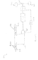
- FIG. 1 shows a series hybrid electric vehicle (HEV) 100 comprising an internal combustion engine 110 having an output shaft arranged to drive a first motor-generator 115.
- the engine 110 has an air intake conduit 117 and an exhaust gas conduit 118.
- the motor-generator 115 is operable to generate electrical current for charging a battery 120.
- the motor-generator 115 is a crankshaft integrated motor-generator (CIMG) 115.
- CIMG crankshaft integrated motor-generator
- Other motor-generator arrangements are also useful such as a belt-integrated starter generator (BISG).
- the CIMG 115 is also operable as an electric motor in order to turn the engine 110 when required.
- the battery 120 is operable to supply electrical current to the CIMG 115 when it is required to operate the CIMG 115 as a motor.
- the battery 120 is also arranged to supply electrical current to a traction motor/generator 130.
- the traction motor/generator 130 is operable as an electric motor to supply motive power to drive a driveshaft 132 of the vehicle 100.
- the driveshaft 132 is arranged in turn to drive a pair of road wheels 107, 109 via a differential 105.
- the traction motor/generator 130 is also operable as an electrical generator driven by the road wheels 107, 109.
- a controller 150 is arranged to control the traction motor/generator 130 to act as a generator.
- the rotating road wheels 107, 109 cause a rotor of the traction motor/generator 130 to turn causing a reverse electromotive force (EMF) to be generated in a stator of the motor/generator 130.
- EMF electromotive force
- This reverse EMF applies a retarding torque to the driveshaft 132, slowing the vehicle.
- the reverse EMF also generates a current which is used to recharge the battery 120 of the vehicle 100.
- the traction motor/generator 130 may be operated as a generator to apply a retarding force to slow the vehicle 100 when an accelerator pedal is released. The amount of the retarding force may be increased if the brake pedal is subsequently depressed.
- 'regenerative braking' The above process of generating electrical current and causing braking of the vehicle 100 is commonly referred to as 'regenerative braking'.
- An event in which the regenerative braking process is performed will be referred to herein as a regenerative braking event.
- regenerative braking allows energy that would otherwise be dissipated as heat by friction brakes of the vehicle 100 to be converted to useful energy in the form of stored electrical charge.
- the controller 150 is arranged to monitor a state of charge (SoC) of the battery 120. If the SoC exceeds a prescribed threshold value and a regenerative braking event occurs in which the traction motor/generator generates electrical power, the controller 150 is arranged to terminate a supply of fuel to the engine 110 (if this has not already occurred) and to control the CIMG 115 to act as a motor to rotate the crankshaft of the engine 110.
- SoC state of charge
- the controller 150 prevents further charging of the battery 120 in order to avoid damage to the battery 120.
- This has the effect in known HEVs that a regenerative braking event cannot be performed. This is because there is no flow path from the traction motor/generator 130 for current generated by the traction motor/generator 130 during a regenerative braking event. Thus substantially no reverse EMF can be generated by the traction motor/generator 130 and therefore no retarding torque can be applied to the driveshaft 132.
- the traction motor/generator 130 (which normally operates as an electric motor) is controlled to operate as a generator and the CIMG 115 (which normally operates as a generator) is controlled to operate as a motor.
- Embodiments of the invention have the advantage that regenerative braking may still be effected by a vehicle even when the battery SoC is such that the battery 120 is unable to accept further charge. This allows the behaviour of the vehicle 100 when the accelerator is released and brake pedal depressed to remain consistent regardless of the SoC of the battery 120. That is, a relative proportion of regenerative and friction braking employed by a vehicle during a braking operation may remain substantially the same regardless of a state of charge of a battery.
- CMIG 115 is controlled to operate as a motor during a regenerative braking event may be relatively rare.
- regenerative braking might occur when the SoC of the battery 120 is high is when the vehicle is travelling at a steady and relatively high speed. Sudden application of the brakes to slow the car using regenerative braking could generate a sufficiently large amount of electrical charge that the battery would be unable to accept the charge. At least some of this charge may therefore be used to drive the CIMG 115 as an electric motor with the supply of fuel to the engine 110 terminated.
- the CIMG 115 when acting as an electrical generator the CIMG 115 may in some embodiments generate around 35kW of electrical energy to charge the battery 120 and power the traction motor/generator 130 as a motor. In a regenerative braking situation the traction motor/generator 130 may generate around 10kW of power for a relatively short period of time. The battery 120 may be unable to accept the 35kW of power generated by the CIMG 115 and the 10kW of power generated by the traction motor/generator 130 (45kW in total) if its SoC is high.
- the amount of electrical power being developed to charge the battery 120 is reduced from 45kW to 10kW and fuel is saved because a supply of fuel to the engine 110 is switched off (or at least substantially reduced, in some embodiments).
- the CIMG 115 is now operated as an electric motor to crank the engine 110 around 2kW of electrical power may be dissipated by the CIMG 115 leaving a total of 8kW of power from the regenerative braking operation for the battery 120 to absorb.
- the vehicle 100 may be arranged to control the battery to accept this charge. In some embodiments this may result in the total SoC of the battery 120 exceeding temporarily a recommended maximum SoC (such as the prescribed level discussed above) in order to maintain consistent performance of the vehicle 100 during the regenerative braking process. This has the advantage that the vehicle 100 performs substantially in the manner expected by the driver during a regenerative braking event regardless of the SoC of the battery 120.
- wear of the friction brakes may also be reduced since a likelihood that use of the friction brakes will be required is reduced.
- the vehicle is configured to drive the CIMG 115 to turn the engine 110 during the regenerative braking event until the amount of current generated by the traction motor/generator 130 falls below a prescribed threshold.
- the controller 150 may then be arranged to restore a supply of fuel to the engine 110 to restart the engine 110.
- the controller 150 may be arranged to terminate rotation of the engine 110 by the CIMG 115 and not to restore the supply of fuel to the engine 110 so that the engine assumes a stationary condition.
- the action taken by the controller 150 may depend on whether the driver applies pressure to the accelerator following the regenerative braking event or allows the vehicle to slow to a standstill. Other arrangements are also useful.
- the controller 150 is also configured to control operation of an engine air intake throttle valve 117V provided in the engine air intake conduit 117.
- the valve 117 is employed by an engine control unit to control an amount of air drawn into the engine 110 when the engine 110 is running under its own power.
- the controller 150 controls the valve 117 to determine an amount by which flow of air into the engine 110 is restricted when the engine is motored by the CIMG 115.
- the controller 150 closes the throttle valve by a prescribed amount in order to increase an amount of work that must be done by the CIMG 115 in motoring the engine 110 at a given speed.
- the amount by which the valve is closed is determined responsive to an amount of excess current developed in a regenerative braking operation that must be dissipated.
- an amount of power that may be dissipated by the engine 110 when airflow through the engine 110 is restricted and the engine 110 is motored may be increased from around 2kW to around 10kW or more, depending on a size of the engine 110.
- substantially the entire amount of the excess power may be dissipated by the CIMG 115 when motoring the engine 110 by restricting a flow of air through the engine 110.
- the battery 120 would therefore be substantially entirely relieved of a requirement to accept regenerated power.
- FIG. 2 shows an engine 210 of a vehicle 200 according to a further embodiment of the invention similar to that of the embodiment of FIG. 1 .
- Like features of the embodiment of FIG. 2 to that of FIG. 1 are provided with like reference signs prefixed numeral 2 instead of numeral 1.
- the engine 210 is coupled to a CIMG 215 arranged to charge a battery 220 under the control of a controller 250.
- the engine 210 has an air intake conduit 217 and an exhaust gas conduit 218.
- an inlet valve 217V is provided in the air intake conduit 217 and an outlet valve 218V is provided in the exhaust gas conduit 218.
- the valves 217V, 218V are operable to prevent flow of gas therepast when required.
- the controller 250 is arranged to close one or both of the inlet valve 217V and outlet valve 218V.
- valves 217V, 218V are provided as in the embodiment of FIG. 1 .
- inlet valve 217V is closed and the engine 210 is cranked (or motored) by the CIMG 215 a gas pressure immediately downstream of the valve 217V will fall below the value of gas pressure present in that region with the valve 217V open.
- outlet valve 218V is closed and the engine 210 is motored by the CIMG 215 a gas pressure immediately upstream of the valve 218V will rise above the value of gas pressure present in that region with the valve 218V open.
- valves 217V, 218V closure of either or both of the valves 217V, 218V has the effect that a greater amount of torque is required to be provided by the CIMG 215 in order to motor the engine 110. Therefore a greater amount of electrical power is dissipated by the CIMG 215 under these circumstances.
- the CIMG 215 is able to provide further relief to the battery 220 in respect of the amount of charge the battery 220 is required to store for a given amount of charge (or power) generated by the traction motor/generator 230 during a regenerative braking event.
- Embodiments of the invention have the advantage that regenerative braking may be performed even under circumstances where a battery SoC is such that regenerative braking would be impossible for or prohibited by known vehicle systems. This in turn allows a performance of a vehicle to remain consistent even under conditions of high SoC of the battery. Furthermore, embodiments of the invention allow a reduction in fuel consumption of a vehicle since a supply of fuel to an engine may be terminated when a regenerative braking event occurs. However, because the CIMG continues to turn the engine, the engine may be more quickly restarted if a supply of fuel to the engine is resumed. It is to be understood that in fuel burning actuators requiring spark ignition of fuel, a controller may be arranged to suspend provision of spark ignition in addition to or instead of terminating a supply of fuel. Other arrangements are also useful.
- controller 150, 250 of the embodiments of FIG. 1 and FIG. 2 may be arranged to monitor an amount of electrical power developed by the traction motor/generator 130, 230 by communicating with a controller associated with the motor/generator such as an inverter arranged to convert DC current to AC current and vice versa.
- a controller associated with the motor/generator such as an inverter arranged to convert DC current to AC current and vice versa.
- the controller is 150, 250 is arranged to communicate with a brake controller such as an anti-lock brake system (ABS) controller.
- the controller 150, 250 may provide an indication to the brake controller of the amount of regenerated power the battery 120, 220 or CIMG 115, 215 is able to dissipate, allowing the brake controller to determine a required brake torque split between a regenerative braking system and a foundation braking system (typically a friction braking system).
- a foundation braking system typically a friction braking system
- the brake controller may attempt to control the vehicle to provide braking in which regenerative braking and foundation braking systems are both used to provide brake torque unless the required brake torque is particularly low in which case only regenerative (or only foundation) braking may be employed.
- Embodiments of the invention have the advantage that because the CIMG 115, 215 is able to dissipate a substantial amount of regenerated electrical power when the battery 120, 220 is unable to receive the power, the brake controller is able consistently to operate according to an optimum brake torque split between regenerative and foundation brake systems regardless of a state of charge (or operational availability) of the battery. This has the advantage that a driver experience when applying brakes of the vehicle is substantially consistent regardless of battery condition.
Landscapes
- Engineering & Computer Science (AREA)
- Chemical & Material Sciences (AREA)
- Combustion & Propulsion (AREA)
- Transportation (AREA)
- Mechanical Engineering (AREA)
- Automation & Control Theory (AREA)
- Power Engineering (AREA)
- Electric Propulsion And Braking For Vehicles (AREA)
- Hybrid Electric Vehicles (AREA)
Applications Claiming Priority (1)
| Application Number | Priority Date | Filing Date | Title |
|---|---|---|---|
| GB1020446.9A GB2486178A (en) | 2010-12-02 | 2010-12-02 | HEV control which dissipates excessive energy when regenerative braking occurs |
Publications (1)
| Publication Number | Publication Date |
|---|---|
| EP2460679A1 true EP2460679A1 (de) | 2012-06-06 |
Family
ID=43531362
Family Applications (1)
| Application Number | Title | Priority Date | Filing Date |
|---|---|---|---|
| EP11191682A Withdrawn EP2460679A1 (de) | 2010-12-02 | 2011-12-02 | Elektrisches Hybridfahrzeug und Steuerverfahren dafür |
Country Status (5)
| Country | Link |
|---|---|
| US (1) | US8386109B2 (de) |
| EP (1) | EP2460679A1 (de) |
| JP (1) | JP6002380B2 (de) |
| CN (1) | CN102555763B (de) |
| GB (2) | GB2486178A (de) |
Cited By (4)
| Publication number | Priority date | Publication date | Assignee | Title |
|---|---|---|---|---|
| CH708588A1 (de) * | 2013-09-16 | 2015-03-31 | Siegfried A Eisenmann | Kraftfahrzeug mit Elektroantrieb. |
| EP2990284A1 (de) * | 2014-08-27 | 2016-03-02 | Mitsubishi Jidosha Kogyo Kabushiki Kaisha | Regenerative steuerungsvorrichtung für ein hybridfahrzeug |
| EP2896543A4 (de) * | 2012-09-11 | 2016-07-27 | Honda Motor Co Ltd | Hybridfahrzeug |
| EP4015327A1 (de) * | 2020-12-17 | 2022-06-22 | Volvo Car Corporation | Verfahren zum bremsen eines hybrid-elektrofahrzeugs |
Families Citing this family (16)
| Publication number | Priority date | Publication date | Assignee | Title |
|---|---|---|---|---|
| US9187083B2 (en) * | 2009-09-16 | 2015-11-17 | Polaris Industries Inc. | System and method for charging an on-board battery of an electric vehicle |
| GB201120114D0 (en) * | 2011-11-22 | 2012-01-04 | Land Rover Uk Ltd | Hybrid electric vehicle and method of control thereof |
| CA2922447A1 (en) * | 2013-08-29 | 2015-03-05 | Honda Motor Co., Ltd. | Generation control apparatus and generation control method |
| JP2015113045A (ja) * | 2013-12-12 | 2015-06-22 | 三菱自動車工業株式会社 | ハイブリッド車両の制御装置 |
| JP6350012B2 (ja) * | 2014-06-23 | 2018-07-04 | 三菱自動車工業株式会社 | 車両の回生制御装置 |
| US10300786B2 (en) | 2014-12-19 | 2019-05-28 | Polaris Industries Inc. | Utility vehicle |
| JP6476839B2 (ja) * | 2014-12-24 | 2019-03-06 | 日産自動車株式会社 | 車両の制御装置 |
| AU2017284964B2 (en) | 2016-06-14 | 2020-07-02 | Polaris Industries, Inc. | Hybrid utility vehicle |
| US20180037205A1 (en) * | 2016-08-02 | 2018-02-08 | Ford Global Technologies, Llc | Vehicle regenerative air brake system |
| CN106114188A (zh) * | 2016-08-30 | 2016-11-16 | 陈华平 | 一种双增程装置及安装有该双增程装置电动动力系统 |
| US10396647B2 (en) * | 2016-10-10 | 2019-08-27 | Mando Corporation | Converter controlling device for hybrid vehicle and converter controlling method for hybrid vehicle |
| US9975619B1 (en) * | 2017-01-11 | 2018-05-22 | Brunswick Corporation | PCM controlled charging system |
| CN108825371B (zh) * | 2018-06-14 | 2021-05-25 | 东华大学 | 一种降低燃油发动机瞬态输出功率波动的方法 |
| US10780770B2 (en) | 2018-10-05 | 2020-09-22 | Polaris Industries Inc. | Hybrid utility vehicle |
| US11370266B2 (en) | 2019-05-16 | 2022-06-28 | Polaris Industries Inc. | Hybrid utility vehicle |
| US11505086B2 (en) | 2019-07-08 | 2022-11-22 | Deere & Company | Vehicle speed control system and method of controlling retardation energy of a vehicle |
Citations (2)
| Publication number | Priority date | Publication date | Assignee | Title |
|---|---|---|---|---|
| US5788597A (en) * | 1994-12-23 | 1998-08-04 | Mercedes-Benz Ag | Process and apparatus for braking a hybrid-drive motor vehicle |
| EP1129889A2 (de) * | 2000-02-24 | 2001-09-05 | Mitsubishi Jidosha Kogyo Kabushiki Kaisha | Vorrichtung zur Regenerationssteuerung bei einem hybridelektrischen Fahrzeug |
Family Cites Families (19)
| Publication number | Priority date | Publication date | Assignee | Title |
|---|---|---|---|---|
| JPS5840401B2 (ja) * | 1975-07-09 | 1983-09-06 | 日産自動車株式会社 | ガスタ−ビントウノ エンジントウサイシヤリヨウノ ホジヨセイドウセイギヨソウチ |
| US6554088B2 (en) * | 1998-09-14 | 2003-04-29 | Paice Corporation | Hybrid vehicles |
| GB2355241A (en) * | 1999-10-14 | 2001-04-18 | Rover Group | A vehicle hill descent control arrangement |
| JP2004225564A (ja) * | 2003-01-20 | 2004-08-12 | Hitachi Unisia Automotive Ltd | ハイブリッド車両の制御装置 |
| US7308959B2 (en) * | 2003-09-15 | 2007-12-18 | General Motors Corporation | Displacement on demand with regenerative braking |
| JP4474293B2 (ja) * | 2005-01-31 | 2010-06-02 | トヨタ自動車株式会社 | ハイブリッド車およびその制御方法 |
| JP4293154B2 (ja) * | 2005-03-30 | 2009-07-08 | 三菱ふそうトラック・バス株式会社 | ハイブリッド車両のモータ制御装置 |
| JP4293182B2 (ja) * | 2005-12-16 | 2009-07-08 | トヨタ自動車株式会社 | ハイブリッド自動車およびその制御方法 |
| JP3966894B2 (ja) * | 2006-07-19 | 2007-08-29 | 本田技研工業株式会社 | ハイブリッド車両 |
| JP4501913B2 (ja) * | 2006-08-25 | 2010-07-14 | マツダ株式会社 | ハイブリッド車両の回生制動制御装置 |
| US20080185194A1 (en) * | 2007-02-02 | 2008-08-07 | Ford Global Technologies, Llc | Hybrid Vehicle With Engine Power Cylinder Deactivation |
| US7828694B2 (en) * | 2007-08-16 | 2010-11-09 | Ford Global Technologies, Llc | Rollback control of a hybrid electric vehicle |
| US7691027B2 (en) * | 2007-11-29 | 2010-04-06 | Ford Global Technologies, Llc | Idle speed control of a hybrid electric vehicle |
| US7980342B2 (en) * | 2008-06-27 | 2011-07-19 | Ford Global Technologies, Llc | Plug-in hybrid electric vehicle |
| JP5200797B2 (ja) * | 2008-09-12 | 2013-06-05 | マツダ株式会社 | ハイブリッド自動車の制御方法及びその装置 |
| JP2010179677A (ja) * | 2009-02-03 | 2010-08-19 | Toyota Motor Corp | 内燃機関の制御装置 |
| US8177006B2 (en) * | 2009-05-28 | 2012-05-15 | Ford Global Technologies, Llc | Plug-in hybrid electric vehicle |
| JP5348549B2 (ja) * | 2009-08-04 | 2013-11-20 | スズキ株式会社 | 電動車両 |
| US8392097B2 (en) * | 2010-07-08 | 2013-03-05 | GM Global Technology Operations LLC | Method for starting an internal combustion engine within a hybrid powertrain |
-
2010
- 2010-12-02 GB GB1020446.9A patent/GB2486178A/en not_active Withdrawn
-
2011
- 2011-12-02 EP EP11191682A patent/EP2460679A1/de not_active Withdrawn
- 2011-12-02 JP JP2011264804A patent/JP6002380B2/ja active Active
- 2011-12-02 US US13/309,884 patent/US8386109B2/en not_active Expired - Fee Related
- 2011-12-02 CN CN201110397704.3A patent/CN102555763B/zh not_active Expired - Fee Related
- 2011-12-02 GB GB1120746.1A patent/GB2486320B/en active Active
Patent Citations (2)
| Publication number | Priority date | Publication date | Assignee | Title |
|---|---|---|---|---|
| US5788597A (en) * | 1994-12-23 | 1998-08-04 | Mercedes-Benz Ag | Process and apparatus for braking a hybrid-drive motor vehicle |
| EP1129889A2 (de) * | 2000-02-24 | 2001-09-05 | Mitsubishi Jidosha Kogyo Kabushiki Kaisha | Vorrichtung zur Regenerationssteuerung bei einem hybridelektrischen Fahrzeug |
Cited By (9)
| Publication number | Priority date | Publication date | Assignee | Title |
|---|---|---|---|---|
| EP2896543A4 (de) * | 2012-09-11 | 2016-07-27 | Honda Motor Co Ltd | Hybridfahrzeug |
| US9566976B2 (en) | 2012-09-11 | 2017-02-14 | Honda Motor Co., Ltd. | Hybrid vehicle |
| EP3536573A3 (de) * | 2012-09-11 | 2020-01-22 | Honda Motor Co., Ltd. | Hybridfahrzeug |
| CH708588A1 (de) * | 2013-09-16 | 2015-03-31 | Siegfried A Eisenmann | Kraftfahrzeug mit Elektroantrieb. |
| EP2990284A1 (de) * | 2014-08-27 | 2016-03-02 | Mitsubishi Jidosha Kogyo Kabushiki Kaisha | Regenerative steuerungsvorrichtung für ein hybridfahrzeug |
| CN105383482A (zh) * | 2014-08-27 | 2016-03-09 | 三菱自动车工业株式会社 | 用于混合动力车辆的再生控制装置 |
| US9688265B2 (en) | 2014-08-27 | 2017-06-27 | Mitsubishi Jidosha Kogyo Kabushiki Kaisha | Regenerative control device for hybrid vehicle |
| CN105383482B (zh) * | 2014-08-27 | 2019-05-10 | 三菱自动车工业株式会社 | 用于混合动力车辆的再生控制装置 |
| EP4015327A1 (de) * | 2020-12-17 | 2022-06-22 | Volvo Car Corporation | Verfahren zum bremsen eines hybrid-elektrofahrzeugs |
Also Published As
| Publication number | Publication date |
|---|---|
| GB2486320B (en) | 2013-07-03 |
| JP2012116474A (ja) | 2012-06-21 |
| GB201120746D0 (en) | 2012-01-11 |
| GB2486178A (en) | 2012-06-13 |
| GB2486320A (en) | 2012-06-13 |
| JP6002380B2 (ja) | 2016-10-05 |
| US20120158230A1 (en) | 2012-06-21 |
| CN102555763B (zh) | 2016-11-09 |
| GB201020446D0 (en) | 2011-01-19 |
| US8386109B2 (en) | 2013-02-26 |
| CN102555763A (zh) | 2012-07-11 |
Similar Documents
| Publication | Publication Date | Title |
|---|---|---|
| US8386109B2 (en) | Hybrid electric vehicle and method of control | |
| US11577713B2 (en) | Method and device for controlling hybrid vehicle | |
| KR100419937B1 (ko) | 하이브리드 전기 자동차의 회생 제어장치 | |
| US9573588B2 (en) | Control device for hybrid vehicle | |
| JP5733200B2 (ja) | ハイブリッド車両の制御装置 | |
| JP5200797B2 (ja) | ハイブリッド自動車の制御方法及びその装置 | |
| CN103079926A (zh) | 再生控制装置、混合动力汽车及再生控制方法、以及程序 | |
| US7024859B2 (en) | Combustion engine acceleration support using an integrated starter/alternator | |
| JP2019069679A (ja) | ハイブリッド車両 | |
| JP2007221885A (ja) | 二次電池の制御装置および制御方法 | |
| KR20090062421A (ko) | 하이브리드 차량의 모터 토크 제한 방법 | |
| CN103068609A (zh) | 再生控制装置、混合动力汽车及再生控制方法、以及程序 | |
| KR101619632B1 (ko) | 하이브리드 차량의 배터리 충전 제어 방법 | |
| JP2008094238A (ja) | ハイブリッド車の制御装置 | |
| JP3672712B2 (ja) | ハイブリッド車両 | |
| JP3784736B2 (ja) | ハイブリッド自動車 | |
| JP2014104833A (ja) | 省エネルギー走行制御方法。 | |
| JP2008213720A (ja) | ハイブリッド自動車 | |
| KR100952018B1 (ko) | 연료전지차량의 회생제동시 부품 보호방법 | |
| JP7461915B2 (ja) | 車両用制御装置 | |
| JP2014069785A (ja) | ハイブリッド車両 | |
| JP2014218171A (ja) | ハイブリッド車両の制御装置及びその制御方法 | |
| US20200231135A1 (en) | Vehicle | |
| JP2013112320A (ja) | ハイブリッド車両 | |
| JP2003235109A (ja) | ハイブリッド自動車 |
Legal Events
| Date | Code | Title | Description |
|---|---|---|---|
| PUAI | Public reference made under article 153(3) epc to a published international application that has entered the european phase |
Free format text: ORIGINAL CODE: 0009012 |
|
| 17P | Request for examination filed |
Effective date: 20111202 |
|
| AK | Designated contracting states |
Kind code of ref document: A1 Designated state(s): AL AT BE BG CH CY CZ DE DK EE ES FI FR GB GR HR HU IE IS IT LI LT LU LV MC MK MT NL NO PL PT RO RS SE SI SK SM TR |
|
| AX | Request for extension of the european patent |
Extension state: BA ME |
|
| RAP1 | Party data changed (applicant data changed or rights of an application transferred) |
Owner name: JAGUAR LAND ROVER LIMITED |
|
| STAA | Information on the status of an ep patent application or granted ep patent |
Free format text: STATUS: EXAMINATION IS IN PROGRESS |
|
| RIC1 | Information provided on ipc code assigned before grant |
Ipc: B60W 10/06 20060101ALI20180718BHEP Ipc: B60W 10/08 20060101ALI20180718BHEP Ipc: B60K 6/46 20071001AFI20180718BHEP Ipc: B60W 30/18 20120101ALI20180718BHEP Ipc: B60W 20/00 20060101ALI20180718BHEP |
|
| STAA | Information on the status of an ep patent application or granted ep patent |
Free format text: STATUS: THE APPLICATION IS DEEMED TO BE WITHDRAWN |
|
| 18D | Application deemed to be withdrawn |
Effective date: 20180503 |
|
| RIC1 | Information provided on ipc code assigned before grant |
Ipc: B60W 10/06 20060101ALI20180718BHEP Ipc: B60W 30/18 20120101ALI20180718BHEP Ipc: B60K 6/46 20071001AFI20180718BHEP Ipc: B60W 20/00 20160101ALI20180718BHEP Ipc: B60W 10/08 20060101ALI20180718BHEP |