EP2458367B1 - Vorrichtung und Verfahren zur Erkennung fester Substanzen in einer flüssigen Phase - Google Patents
Vorrichtung und Verfahren zur Erkennung fester Substanzen in einer flüssigen Phase Download PDFInfo
- Publication number
- EP2458367B1 EP2458367B1 EP10192601.2A EP10192601A EP2458367B1 EP 2458367 B1 EP2458367 B1 EP 2458367B1 EP 10192601 A EP10192601 A EP 10192601A EP 2458367 B1 EP2458367 B1 EP 2458367B1
- Authority
- EP
- European Patent Office
- Prior art keywords
- pixel values
- container
- mixture
- solid substance
- areas
- Prior art date
- Legal status (The legal status is an assumption and is not a legal conclusion. Google has not performed a legal analysis and makes no representation as to the accuracy of the status listed.)
- Active
Links
Images


Classifications
-
- G—PHYSICS
- G01—MEASURING; TESTING
- G01N—INVESTIGATING OR ANALYSING MATERIALS BY DETERMINING THEIR CHEMICAL OR PHYSICAL PROPERTIES
- G01N13/00—Investigating surface or boundary effects, e.g. wetting power; Investigating diffusion effects; Analysing materials by determining surface, boundary, or diffusion effects
-
- G—PHYSICS
- G01—MEASURING; TESTING
- G01N—INVESTIGATING OR ANALYSING MATERIALS BY DETERMINING THEIR CHEMICAL OR PHYSICAL PROPERTIES
- G01N15/00—Investigating characteristics of particles; Investigating permeability, pore-volume or surface-area of porous materials
- G01N15/02—Investigating particle size or size distribution
- G01N15/0205—Investigating particle size or size distribution by optical means
- G01N15/0227—Investigating particle size or size distribution by optical means using imaging; using holography
-
- G—PHYSICS
- G01—MEASURING; TESTING
- G01N—INVESTIGATING OR ANALYSING MATERIALS BY DETERMINING THEIR CHEMICAL OR PHYSICAL PROPERTIES
- G01N15/00—Investigating characteristics of particles; Investigating permeability, pore-volume or surface-area of porous materials
- G01N15/10—Investigating individual particles
- G01N15/14—Optical investigation techniques, e.g. flow cytometry
- G01N15/1429—Signal processing
- G01N15/1433—Signal processing using image recognition
-
- G—PHYSICS
- G01—MEASURING; TESTING
- G01N—INVESTIGATING OR ANALYSING MATERIALS BY DETERMINING THEIR CHEMICAL OR PHYSICAL PROPERTIES
- G01N21/00—Investigating or analysing materials by the use of optical means, i.e. using sub-millimetre waves, infrared, visible or ultraviolet light
- G01N21/84—Systems specially adapted for particular applications
- G01N21/88—Investigating the presence of flaws or contamination
- G01N21/90—Investigating the presence of flaws or contamination in a container or its contents
- G01N21/9018—Dirt detection in containers
- G01N21/9027—Dirt detection in containers in containers after filling
-
- G—PHYSICS
- G01—MEASURING; TESTING
- G01N—INVESTIGATING OR ANALYSING MATERIALS BY DETERMINING THEIR CHEMICAL OR PHYSICAL PROPERTIES
- G01N13/00—Investigating surface or boundary effects, e.g. wetting power; Investigating diffusion effects; Analysing materials by determining surface, boundary, or diffusion effects
- G01N2013/003—Diffusion; diffusivity between liquids
-
- G—PHYSICS
- G01—MEASURING; TESTING
- G01N—INVESTIGATING OR ANALYSING MATERIALS BY DETERMINING THEIR CHEMICAL OR PHYSICAL PROPERTIES
- G01N13/00—Investigating surface or boundary effects, e.g. wetting power; Investigating diffusion effects; Analysing materials by determining surface, boundary, or diffusion effects
- G01N2013/006—Dissolution of tablets or the like
-
- G—PHYSICS
- G01—MEASURING; TESTING
- G01N—INVESTIGATING OR ANALYSING MATERIALS BY DETERMINING THEIR CHEMICAL OR PHYSICAL PROPERTIES
- G01N15/00—Investigating characteristics of particles; Investigating permeability, pore-volume or surface-area of porous materials
- G01N15/10—Investigating individual particles
- G01N15/14—Optical investigation techniques, e.g. flow cytometry
- G01N15/1468—Optical investigation techniques, e.g. flow cytometry with spatial resolution of the texture or inner structure of the particle
- G01N2015/1472—Optical investigation techniques, e.g. flow cytometry with spatial resolution of the texture or inner structure of the particle with colour
-
- G—PHYSICS
- G01—MEASURING; TESTING
- G01N—INVESTIGATING OR ANALYSING MATERIALS BY DETERMINING THEIR CHEMICAL OR PHYSICAL PROPERTIES
- G01N33/00—Investigating or analysing materials by specific methods not covered by groups G01N1/00 - G01N31/00
- G01N33/15—Medicinal preparations ; Physical properties thereof, e.g. dissolubility
Definitions
- the present invention relates to an apparatus and a method for detecting solid substances in a liquid phase, wherein the solid substance and the liquid phase are included as a mixture in an at least partially transparent container.
- liquids In many areas of industry, in particular in production, research and development, liquids must be periodically examined for the presence of solid substances, for example particles of powders, suspended matter and the like.
- solid substances in pasty, powdery or granular form must be dissolved in a liquid phase.
- One or more solid substances are metered into a container and the liquid phase, usually water or an organic solvent such as ethanol, added either by weight or volume.
- the concentration of the solution resulting from the dissolution process depends crucially on whether or not all solid constituents have been dissolved.
- the device described above has the disadvantage that the measurement of the resonance frequency can be negatively influenced by the agitator. Furthermore, substance particles above the liquid level can adhere to the wall of the container and not go into solution. Furthermore, the transmitter and the receiver are embedded in the housing wall of the container and thus come into contact with the solution.
- WO 03/098199 A1 deals with a detection system for measuring the release of an active substance from a pharmaceutical dosage form.
- US 2004/0168529 A1 deals with methods and systems for the determination of solubility profiles of sample materials.
- the object of the present invention is therefore to provide an apparatus and a method by which the detection of solid substances in a liquid phase is made possible or the dissolution process of a mixture of at least one solid substance and one liquid phase can be monitored, without the device to contaminate.
- a device for detecting solid substances in a liquid phase comprises a camera for generating digitized images and a processor unit. These digitized images are captured as an array of pixels with their associated pixel values.
- the solid substance and the liquid phase are included as a mixture in an at least partially transparent container.
- a partially transparent container means that at least one point of the walls forming the container is permeable to electromagnetic waves with little absorption.
- the remaining locations of the walls of the container can be configured as desired or can be designed to support the purpose of the invention.
- the parts used for the device must therefore be matched to the electromagnetic waves to be used. If, for example, daylight is used and this is sufficient to illuminate the mixture, it is not absolutely necessary for a lighting device to be present. However, as explained below, a lighting device is recommended for optimum results.
- the device further comprises a movement device for receiving the container, by means of which movement device the container can be moved in order thereby to supply kinetic energy to the mixture.
- the primary purpose of supplying kinetic energy is to keep the mixture trapped in the container in motion. Usually, the mixture or the solution remains in motion even after switching off the movement device for a certain time. These motions of the mixture are exploited to detect solid matter in a liquid phase, as described below.
- the supply of kinetic energy can fulfill two secondary tasks.
- the solid substance is dissolved more rapidly due to mixing and turbulent flows present in the liquid phase. Because the container is closed, it can be arbitrarily rotated and shaken by means of the movement device, so that, secondly, all the solid substance particles come into contact with the liquid phase and, if appropriate, are dissolved.
- the container is releasably connected in the operating state of the device with a recording of the movement device.
- the recording of the movement device is connected via a take-up shaft with a drive.
- processor unit is understood to mean any device which can process and store digital data, for example a Process control system, a connectable to the other parts of the device computer or laptop, but also integrated solutions such as a arranged in the movement device board with a processor, a built-in camera arithmetic unit or an FPGA (Field Programmable Gate Array), with memory modules and one connected input / output unit.
- a Process control system for example a processor, a connectable to the other parts of the device computer or laptop, but also integrated solutions such as a arranged in the movement device board with a processor, a built-in camera arithmetic unit or an FPGA (Field Programmable Gate Array), with memory modules and one connected input / output unit.
- FPGA Field Programmable Gate Array
- the camera is directed to a transparent location of the container for imaging the moving mixture.
- digitized recordings of the moving mixture are generated during a recording phase and transmitted to the processor unit.
- the purpose of generating digitized images is to separate the static image component from the dynamic image component in the subsequent evaluation process.
- the static image portion comprises all parts of the container and the environment of the container, the dynamic image portion comprises the moving in the container mixture.
- the camera can also be fixedly connected to the container or synchronously tracked in the recording phase, so that it follows each movement of the container during the recording phase.
- the recording phase can be done not only in the resting phases of the container, but also during the supply of kinetic energy.
- the triggering time of the camera can be coupled to a specific position of the container so that the container is always recorded in apparently the same position to its surroundings.
- a fourth possibility is to take arbitrary shots of the moving container, wherein the subsequent evaluation process requires considerably more computing power and is therefore not recommended.
- the camera During the recording phase, the camera generates at least one series comprising at least two digitized recordings of the moving mixture.
- these digitized images are preferably stored in a buffer stored. From at least two of the digitized images, an analysis image of the moving mixture can be generated.
- the analysis image is generated by means of the processor unit from two digitized images of the same series by subtracting the pixel values of a first image from the pixel values of a second image.
- the moving solid substance parts of the mixture are recognizable as contrast surfaces or as different pixel values.
- an average image is calculated from a series of preceding digitized images.
- the analysis image is generated by subtracting the pixel values of the average image from the pixel values of a digitized image. Also on this analysis image, the moving solid substance parts of the mixture are recognizable as contrast surfaces or as different pixel values.
- the analysis image is generated by means of a motion estimation of the individual pixels of at least two digitized images, wherein the motion estimation defines all pixels as static image components whose motion vectors in the images are 0 to each other.
- the positions of the individual pixels and their pixel values must be compared with the surrounding pixels and their pixel values with considerably greater computational effort.
- the solid substance parts of the mixture moving as a dynamic image component can be recognized as contrast surfaces or as different pixel values.
- the camera may comprise a lens or a pinhole for projecting the image of the agitated mixture onto its image plane.
- the image plane is provided with a two-dimensional array of radiation sensors.
- this two-dimensional arrangement of radiation sensors is referred to below as a sensor element.
- sensor elements for electromagnetic waves such as CCD sensors, active pixel sensors, Focal Plane arrays, sensor elements for X-rays and such more.
- the two-dimensional image projected onto the image plane is captured by the camera in the form of a two-dimensional array of pixels or pixels and the digital data generated for each pixel represents the color and luminance.
- the contributions of the light will be different Points of the moving mixture, to the pixel value representing the color and intensity of a particular pixel.
- a grayscale camera logically eliminates the color.
- the container may be a cylinder with a cylindrical cross-section, wherein the curvature of the glass, the edge region of the container hardly allows an evaluable image of the moving mixture.
- any closable container of any shape is usable, provided that it has at least one transparent point.
- the device and the container can be used for pure analysis, that is, that an unknown liquid to be examined for the presence of solid substance or a possible dissolution process has already taken place and filled to be examined, finished solution in the container and this in the device according to the invention is used. It makes sense, but the solution is prepared in the container.
- the configuration of the container can accordingly be optimized for the intended use as a mixing and analysis container, so that the inner contour of the container optimally supports the dissolution process of the solid substance in the liquid phase as a result of the introduced kinetic energy. This is possible, for example, by narrowing in sections of the container, but also by avoiding corners in which "dead water areas" can form and inhibit the dissolution process of the solid substance accumulated there.
- the walls of the container can also be optimized for the optical analysis method.
- distortion-free regions formed in the wall may be formed, to which the camera is directed for acquiring the digitized images.
- Focusing or scattering lenses may also be formed in the wall.
- any transparent material is suitable for the formation of the transparent area, especially glass and transparent plastics. The choice of the suitable material depends essentially on the choice of the liquid phase or the solvent and the properties of the solid substance in its solid and / or dissolved form.
- the container may have another transparent location or a location of low opacity to optimally support the illumination of the mixture to be detected.
- At least one evaluation area is selected from the analysis image in a development of the subject matter of the invention. Subsequently, the evaluation area is examined for contrast surfaces. Of course, a section from the first recording and the second recording can also be selected and from these sections an analysis image resulting in the evaluation region can be generated.
- the at least one evaluation region can also be segmented into segment surfaces of the same or different size. This has the advantage that the individual segment areas can be evaluated separately and thereby sequentially smaller amounts of data must be processed. Further, by segmentation in the subsequent statistical evaluation, local extremes can be searched, thereby making the device more sensitive to the detection of particles.
- the examination is carried out by evaluating the frequency distribution of the pixel values within an analysis image or a segment area.
- a predetermined bandwidth of pixel values of the frequency distribution is not taken into account in a further evaluation.
- the predetermined bandwidth of pixel values can be determined, for example, with a clear reference solution without undissolved substance.
- the device may further comprise a source emitting electromagnetic waves tuned to the sensor element of the camera. Since most commercially available cameras operate in the visible light range and therefore cause low procurement costs, the device preferably has at least one planar illumination device.
- the container through which Moving device moves, for example, can be arranged between the planar lighting device and the camera. As a result, the mixture is backlit by the planar lighting device.
- the planar light source can of course also be directed in any spatial position on the container, so that only by the particles of the solid substance scattered and / or deflected light hits the camera.
- the device may have at least one punctiform illumination device, a so-called spot.
- the electromagnetic waves or light waves of the at least one point-shaped illumination device are directed to the transparent position of the container to be detected by the camera.
- the light waves reflected, deflected or partially absorbed by the particles of the mixture are detected by the sensor element of the camera as light and dark contrast surfaces and result in distinguishable pixel values relative to the liquid phase pixel values.
- the container is moved by the moving device.
- the movements can take place in any direction, for example, the movement device can oscillate the container in its longitudinal direction, pivot, rotate or rotate the container several times over head.
- the important thing is that as many substance particles as possible can be set in motion so that they move relative to the container and are thus recognizable.
- a safe control of whether solid substance is present in the liquid phase is given when no particle adheres to the inside of the container wall. So that all solid substance particles can be safely reached by the liquid phase and do not adhere, for example, in an unwetted region of the container wall, the movement device can be designed such that the container is also rotatable about its central longitudinal axis.
- the movement device can also be used for a dissolution process. In order to spare the movement device, the dissolution process or at least the most part of the Dissolution process even before the onset of the container in the inventive device done.
- the container is releasably connected in the operating state of the device with a recording of the movement device.
- the recording of the movement device is connected via a take-up shaft with a drive.
- the method can be supplemented by the further step that at least one evaluation region is selected from the analysis image.
- at least one evaluation region is selected from the analysis image.
- a section from two digitized images of the same series can also be selected and from these sections an analysis image resulting in the evaluation region can be generated.
- the method according to the invention can be supplemented by the further steps that the analysis image or the at least one evaluation region is segmented into segmental surfaces of the same or different size and each Segment surface is examined for the presence of contrast surfaces or to different pixel values.
- the analysis of the analysis image or the segment surface can be carried out by evaluating their frequency distribution of the pixel values and not taking into account a predetermined pixel value bandwidth of the frequency distribution in a further evaluation in order to eliminate camera-related noise.
- the method may comprise the further steps of determining the number of segment areas whose frequency distribution has pixel values deviating from the predetermined pixel value bandwidth, this number of segment areas being a measure of the amount of solid substance present and / or of the progress of the dissolution process. Alternatively, the number of pixel values that exceed a predefined threshold outside the bandwidth can also be determined. The fewer segment areas have different pixel values, the fewer particles are contained in the solution. If only a section of the solution is considered, it is preferable to make several series of images and to process and evaluate them as described above in order to be able to make a reliable statement about the state of the mixture to be investigated. Between the series kinetic energy can be supplied to the mixture by means of the movement device again.
- a more precise statement can be achieved by the further steps that the segment areas whose frequency distribution deviate from the predetermined pixel value bandwidth are weighted according to a predetermined mode and the weighted values of the segment areas are added, the sum of the values also being a measure for the present amount of solid substance and / or for the progress of the dissolution process.
- weighting for example, very dark and very bright contrasting surfaces are taken into greater account because they indicate large particles. Due to the size of the particles, the dissolution process and in particular the time required for this purpose are known to be strongly influenced.
- the FIG. 1 1 shows a schematic representation of a device 100 according to the invention for detecting a solid substance 153 in a liquid phase 154.
- the device 100 has a movement device 110 for a container 150 and also contains a camera 140, at least one illumination device 113, 118 and a processor unit 130.
- the lighting device 113, 118 is not absolutely necessary if the solid substance 153 can be detected by the camera 140 even without it.
- the solid substance 153 and the liquid phase 154 are filled as a mixture in a container 150. As indicated, the container 150 is not filled to the brim, it is still a small volume of gas 155 included.
- the Container 150 has a container closure 152 and a bottle-shaped body, which is made of transparent material, such as glass or plastic.
- the bottle-shaped body is also the transparent location 151 of the container 150.
- the container 150 is horizontally arranged in the operating state of the device 100 in its longitudinal direction and releasably connected to a receptacle 111 of the movement device 110.
- the receptacle 111 can be, for example, a three-jaw chuck or a clamping sleeve into which a partial region of the container 150 can be clamped.
- differently designed receptacles 111 can be used, their execution and operation are at the discretion of the skilled person and are tuned to the one or more containers to be used 150.
- the receptacle 111 is connected via a receiving shaft 112 with a drive, not shown, wherein the drive on the receiving shaft 112 can generate oscillating movements 171 in the longitudinal direction. Further, by the drive, the drive shaft 112 can be offset in a rotational movement 172 about its central longitudinal axis. As a result, the liquid phase 154 can reach any area of the interior of the container 150, including particles of the solid substance 153, which adhere to the wall of the container 150 in the region of the gas volume 155.
- the mixture When the drive of the moving device 110 is turned off and the container 150 and the camera 140 are thus in a picking up phase, the mixture has an evanescent kinetic energy visibly detected by steadily slowing down swirling solid substance 153 is.
- the effect of the visually perceptible movements can be used for detecting solid substance in the liquid phase or for monitoring a dissolution process, if at least one series of at least two images of the moving mixture is taken by the camera 140 in the recording phase.
- the container 150 is disposed between a planar illumination device 113 and the camera 140, so that the light waves 173, 174 of the planar illumination device 113 penetrate the transparent location 151 of the container 150 and the mixture enclosed therein and of the objective 141 of the camera 140 can be detected.
- Some of the light waves 173, 174 are absorbed, reflected or deflected by the solid substance 153, as a result of which contrast surfaces which appear lighter or darker on the images than the base surface of the image which is generated by the light waves 173, 174 penetrating the liquid phase 153 becomes.
- a punctiform illumination device 118 or a spot may also be used. Its light waves 175 are preferably aligned at an angle to the image plane of the camera 140 in order to better illuminate the side surfaces of the solid substance 153.
- a processor unit 130 For controlling the device and the method for monitoring dissolution processes of solid substances 153 in a liquid phase 154, there is a processor unit 130 which is connected via connecting lines 115, 116, 117, 119 is connected to the movement device 110, the planar and / or punctiform illumination device 113, 118 and the camera 140.
- electrical and / or optical connection lines 115, 116, 117, 119 can be used.
- the individual parts of the device 100 can also communicate with one another via wireless connections, with each part of the device 100 requiring its own energy supply.
- the digital recordings generated by the camera 140 are transmitted to the processor unit 130 and processed and evaluated by the latter.
- the processor unit 130 can reactivate the drive of the movement device 110 in order to dissolve the remaining solid substance 153 or to re-supply kinetic energy to the mixture or solution in order to record another series of digital recordings for control purposes. Furthermore, it can be estimated on the basis of several evaluated series, how long the current dissolution process could take.
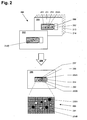
- FIG. 2 The processing of the digital images generated by the camera 140 is schematically illustrated in FIG FIG. 2 shown.
- the recording phase described above at least one series 200 of at least two digital recordings 211, 212 of the transparent location 251 or of the moving mixture 258 which can be viewed at this location is made.
- the mixture 258 of solid substance 253A and liquid phase 254, the gas volume 255, the transparent body 251 formed as a bottle-shaped body and the container closure 252 can be seen.
- the second digital shot 212 Exactly the same elements are also shown on the second digital shot 212.
- the only difference between the two digital images 211, 212 is that on the second digital image 212, the positions of the solid substance particles 253B have changed to the positions of the solid substance particles 253A of the first digital image 211.
- the individual particles of the solid substance 253A, 253B can be recognized as contrast surfaces on the two receptacles 211, 212 and have different pixel values for the liquid phase 254, which can be recognized as the base area.
- the pixel values of the second shot 212 are subtracted from the pixel values of the first shot 211, and an analysis image 220 is generated with the pixel values resulting from the subtraction.
- the analysis image 220 has twice the number of contrast surfaces due to the difference formation.
- the contrast surfaces of the solid substance 253A of the first receptacle 211 stand out darkly from the base of the liquid phase 254.
- the intersecting contour of the liquid level 257 between the gas volume 255 and the liquid phase 254 darkens.
- the contrast surfaces of the solid substance 253B of the second receptacle 212 stand out brightly from the base of the liquid phase 254. So that the overlapping contour of the liquid level 257 does not flow into the evaluation, an evaluation region 290 can be selected from the analysis image 220, wherein only the contrast surfaces present within this evaluation region 290 are evaluated.
- the selection of the evaluation area 290 can also take place before the calculation of the analysis image 220, the corresponding sections being selected from the digitized images 211, 212 and only the pixel values of these sections being calculated. This procedure is particularly advantageous when using processor units 130 with low computing power and low storage capacities.
- an average image can be calculated from the first digitized image 211 and further digitized images 213, 214 of the same series 200.
- the analysis image 220 is generated by subtracting the pixel values of the average image from the pixel values of the second digitized image 212.
- the moving particles 253A, 253B of the mixture can be recognized as contrast surfaces or as different pixel values.
- Another possible method is to generate the analysis image 220 by means of a motion estimation of the individual pixels of at least two digitized images 211, 212.
- the motion estimation all pixels become static image portion defined, their motion vectors in the images 211, 212 to each other zero. This means that the positions of the individual pixels and their pixel values must be compared with the surrounding pixels and their pixel values with considerably greater computational effort.
- the particles of the solid substance 253A, 253B of the mixture moving as a dynamic image component are recognizable as contrast surfaces or as different pixel values.
- the evaluation area 290 is segmented into segment areas 291 of the same size or area.
- the segment surfaces 291 may also have different sizes and individual segment surfaces may be disregarded in the further evaluation. This may be necessary if, for example, individual locations of the container reflect the electromagnetic waves, these locations lie in the evaluation area 290 and are thus "blind spots".
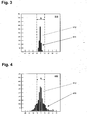
- FIG. 3 In the representation of a first histogram 310, a first frequency distribution 311 of pixel values of a segment area is shown, wherein due to the existing pixel values, this segment area has no contrast areas.
- the abscissa plots the positive (bright) and negative (dark) pixel values deviating from the mean pixel value zero (gray), the ordinate the number of pixel values having the same pixel value size.
- Each camera or its sensor element generates a series of pixel values as a digital recording. Even when shooting a uniformly illuminated, monochrome area, some pixel values usually deviate from the expected, identical pixel values.
- a bandwidth 312 of pixel values of the first frequency distribution 311 excluded from further evaluation.
- the predetermined bandwidth B with the width B is thus also a measure of the sensitivity and reliability of the device.
- a narrower bandwidth 312 can also be defined and for this purpose a certain maximum number of pixel values outside the bandwidth 312 can be permitted. It is then advisable to determine the mass of the number of pixel values outside the bandwidth 312 relative to the total number of pixels of the segment area 291.
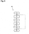
- FIG. 4 In the representation of a histogram 410, a second frequency distribution 411 of pixel values of a segment area is shown. Unlike in the FIG. 3 , the second frequency distribution is 411 in the FIG. 4 significantly wider, which also provides pixel values outside the predetermined bandwidth 412. This indicates that the considered segment surface has contrasting surfaces. Now the number of segment surfaces can be counted with contrast surfaces, this number of segment surfaces being a measure of the amount of solid substance present and / or of the progress of the dissolution process.
- FIG. 5 A flow chart 500 with the essential method steps of the method according to the invention is shown in FIG FIG. 5 shown.
- an operational device 100 is used, as described in the FIG. 1 is shown.
- the device features with the reference numerals of FIG. 1 , the processing of digitized recordings with the reference numerals of FIG. 2 and the method steps with the reference numerals of FIG. 5 Mistake.
- the container 150 is moved by means of the movement device 110 and kinetic energy is thereby supplied to the mixture 258.
- the container 150 is brought into a receiving phase by switching off the drive of the moving device 110 and at least one series 200 is made with at least two digitized receptacles 211, 212 of the mixture 258 moved in the stationary container 150.
- the subtraction of two digitized images 211, 212 of the same series computes an analysis image 220, wherein the moving parts of the solid substance 153, 253A, 253B are recognizable as contrast surfaces or different pixel values.
- the methods described above with an average image or with the motion estimation can also be used to generate the analysis image 220.
- the analysis image 220 is examined for the presence of contrast areas or different pixel values. With the completion of the examination of the analysis image 220, the end 520 of the sequence of absolutely necessary process steps has been reached. If contrast surfaces are found in the examination of the analysis image 220 and it is a resolution process, the preceding method steps 511, 512, 513, 514 can be repeated until no more contrast surfaces can be detected. This repeat loop is shown by the broken line.
- FIG. 6 shows a detailed flowchart 600 of the inventive method with further possible method steps.
- the entire method can be mapped in a computer program or in a firmware, so that the programmed method can be processed step by step by the processor unit.
- the in connection with the FIG. 5 already discussed steps and device features have the same reference numerals and are no longer explained.
- a first supplement is a fifth step 515, in which at least one evaluation region 290 is selected from the analysis image 220 so that it interferes Edge areas such as the gas volume 255 or the liquid level 257 do not adversely affect the evaluation.
- This evaluation region 290 is segmented in a sixth step 516 into segment surfaces 291 of the same size.
- each segment area 291 is examined for the presence of contrast areas or different pixel values. This happens because the frequency distribution 311, 411 of the pixel values is evaluated within a segment area and a predetermined pixel value bandwidth 312, 412 of the frequency distribution 311, 411 is not taken into account in a further evaluation to eliminate camera-related noise.
- the number of segment areas 291 whose frequency distribution 411 has pixel values deviating from the predetermined pixel value bandwidth 412 can now be determined.
- the number of segment surfaces 291 already represents a measure of the amount of solid substance present and / or of the progress of the dissolution process.
- An even more precise evaluation can be obtained in a ninth step 519 if the segment areas 291 whose frequency distribution 411 has pixel values deviating from the predetermined pixel value bandwidth 412 are weighted according to a predetermined mode.
- the weighting can be effected, for example, by multiplying the respective number of a corresponding pixel value by a factor, and this factor being dependent on the removal of the corresponding pixel value from the pixel value zero.
- weighting for example, very dark and very bright contrasting surfaces are taken into greater account because they indicate large particles. Due to the size of the particles, the dissolution process and in particular the time required for this purpose are known to be strongly influenced.
- the weighted values of the segment areas 291 can then be added together, the sum of the values again representing a measure of the amount of solid substance present and / or of the progress of the dissolution process.
- the further procedure can be determined based on this more precise evaluation. For example, it can be estimated how long it will be necessary to shake until no more contrast surfaces can be detected.
- the preceding process steps 511, 512, 513, 514, 515, 516, 517 518, 519 are repeated again for final inspection of the solution perform. This repeat loop is shown by the dotted line.
- the device according to the invention and the method according to the invention can also be used for monitoring the mixing process of two or more liquids, if the liquids to be mixed have mutually distinguishable colors and / or their refractive index is different, so that unmixed regions recognizable as streaks can be detected by the camera are.
- the replacement of the solid substance mentioned herein by a further liquid phase having optically distinguishable liquid-phase properties is therefore within the scope of the independent claims.
Landscapes
- Chemical & Material Sciences (AREA)
- General Health & Medical Sciences (AREA)
- Immunology (AREA)
- Health & Medical Sciences (AREA)
- Analytical Chemistry (AREA)
- Biochemistry (AREA)
- Physics & Mathematics (AREA)
- General Physics & Mathematics (AREA)
- Life Sciences & Earth Sciences (AREA)
- Pathology (AREA)
- Dispersion Chemistry (AREA)
- Engineering & Computer Science (AREA)
- Signal Processing (AREA)
- Investigating Or Analysing Materials By Optical Means (AREA)
- Investigating Materials By The Use Of Optical Means Adapted For Particular Applications (AREA)
Priority Applications (5)
| Application Number | Priority Date | Filing Date | Title |
|---|---|---|---|
| EP10192601.2A EP2458367B1 (de) | 2010-11-25 | 2010-11-25 | Vorrichtung und Verfahren zur Erkennung fester Substanzen in einer flüssigen Phase |
| PL10192601T PL2458367T3 (pl) | 2010-11-25 | 2010-11-25 | Urządzenie oraz sposób do rozpoznawania substancji stałych w fazie ciekłej |
| JP2011245636A JP5918508B2 (ja) | 2010-11-25 | 2011-11-09 | 液相中の固形物検出用の装置および方法 |
| US13/298,611 US8708548B2 (en) | 2010-11-25 | 2011-11-17 | Apparatus and method for the detection of solid substances in a liquid phase |
| CN2011103992804A CN102565087A (zh) | 2010-11-25 | 2011-11-24 | 用于探测液相中的固态物质的仪器和方法 |
Applications Claiming Priority (1)
| Application Number | Priority Date | Filing Date | Title |
|---|---|---|---|
| EP10192601.2A EP2458367B1 (de) | 2010-11-25 | 2010-11-25 | Vorrichtung und Verfahren zur Erkennung fester Substanzen in einer flüssigen Phase |
Publications (2)
| Publication Number | Publication Date |
|---|---|
| EP2458367A1 EP2458367A1 (de) | 2012-05-30 |
| EP2458367B1 true EP2458367B1 (de) | 2015-08-05 |
Family
ID=43899576
Family Applications (1)
| Application Number | Title | Priority Date | Filing Date |
|---|---|---|---|
| EP10192601.2A Active EP2458367B1 (de) | 2010-11-25 | 2010-11-25 | Vorrichtung und Verfahren zur Erkennung fester Substanzen in einer flüssigen Phase |
Country Status (5)
| Country | Link |
|---|---|
| US (1) | US8708548B2 (pl) |
| EP (1) | EP2458367B1 (pl) |
| JP (1) | JP5918508B2 (pl) |
| CN (1) | CN102565087A (pl) |
| PL (1) | PL2458367T3 (pl) |
Families Citing this family (22)
| Publication number | Priority date | Publication date | Assignee | Title |
|---|---|---|---|---|
| DE102011003140A1 (de) * | 2011-01-25 | 2012-07-26 | Hamilton Bonaduz Ag | Optisches Analyseverfahren für Flüssigkeit in einem Probenbehälter und Analyseeinrichtung zur Durchführung des Verfahrens |
| TWI708052B (zh) | 2011-08-29 | 2020-10-21 | 美商安美基公司 | 用於非破壞性檢測-流體中未溶解粒子之方法及裝置 |
| WO2015070262A1 (en) * | 2013-11-11 | 2015-05-14 | Distek, Inc. | Apparatus and methods for disintegration testing |
| US10878551B2 (en) * | 2014-01-27 | 2020-12-29 | Baxter International Inc. | Visual inspection system for automated detection of particulate matter in flexible medical containers |
| DE102014006835A1 (de) * | 2014-05-13 | 2015-11-19 | Kocher-Plastik Maschinenbau Gmbh | Prüfvorrichtung zum Überprüfen von Behältererzeugnissen |
| US11209410B2 (en) | 2014-06-10 | 2021-12-28 | Logan Instruments Corporation | Dissolution tester assembly with integrated imaging system |
| FI127992B (fi) * | 2014-08-29 | 2019-07-15 | Svanbaeck Sami | Menetelmä ja järjestelmä aineen liukenemisominaisuuksien määrittämiseksi |
| CN105136803B (zh) * | 2015-04-27 | 2017-12-12 | 内蒙古科技大学 | 用于气力输送中检测固相物质浓度/颗粒度大小的装置 |
| EP3449236B1 (en) * | 2016-04-29 | 2024-03-13 | The Solubility Company Oy | Method and device for physicochemical characterization of materials |
| KR102196816B1 (ko) * | 2016-09-02 | 2020-12-30 | 암겐 인코포레이티드 | 용기에서의 입자 검출 개선을 위한 비디오 트리거 동기화 |
| US10088660B2 (en) | 2017-02-10 | 2018-10-02 | Amgen Inc. | Imaging system for counting and sizing particles in fluid-filled vessels |
| EP3496031B1 (en) * | 2017-12-11 | 2020-07-08 | Uponor Oyj | Detecting microscopic objects in fluids |
| CN108693187B (zh) * | 2018-06-21 | 2023-12-19 | 上海工程技术大学 | 一种用于散纤维连续取样的动态循环装置及其使用方法 |
| GB201821331D0 (en) * | 2018-12-31 | 2019-02-13 | 3M Innovative Properties Co | Inhaler detection |
| US20220146437A1 (en) * | 2019-03-19 | 2022-05-12 | Nec Corporation | Product-inspection apparatus, product-inspection method, and non-transitory computer readable medium |
| CN109991134B (zh) * | 2019-03-29 | 2020-10-16 | 苏州精濑光电有限公司 | 一种落尘检测设备 |
| CN111595848A (zh) * | 2019-09-01 | 2020-08-28 | 中国铁道科学研究院集团有限公司铁道建筑研究所 | 一种基于液体分散的机制砂生产质量信息化监控系统 |
| WO2021183103A1 (en) * | 2020-03-09 | 2021-09-16 | West Pharmaceutical Services, Inc. | Systems and methods for released particle testing |
| CN111298682A (zh) * | 2020-04-08 | 2020-06-19 | 杭州筋钢人健康科技有限公司 | 对胶状形态的混合物的加工装置 |
| EP4264240A1 (en) * | 2020-12-18 | 2023-10-25 | SiO2 Medical Products, Inc. | Methods for inspecting pharmaceutical containers for particles and defects |
| WO2025027717A1 (ja) * | 2023-07-28 | 2025-02-06 | 日本電気株式会社 | 検査装置 |
| WO2025154143A1 (ja) * | 2024-01-15 | 2025-07-24 | 日本電気株式会社 | 検査装置 |
Family Cites Families (30)
| Publication number | Priority date | Publication date | Assignee | Title |
|---|---|---|---|---|
| US3576442A (en) * | 1966-11-26 | 1971-04-27 | Hoshitaka Nakamura | Ampul inspector using multiple line scan cathode-ray tube |
| US3627423A (en) * | 1970-02-17 | 1971-12-14 | Schering Corp | Method and apparatus for detecting particular matter in sealed liquids |
| US3914058A (en) * | 1970-02-17 | 1975-10-21 | Schering Corp | Method for inspecting liquids in transparent containers |
| US3830969A (en) * | 1971-10-14 | 1974-08-20 | Princeton Electronic Prod | System for detecting particulate matter |
| US4136930A (en) * | 1977-01-10 | 1979-01-30 | The Coca-Cola Company | Method and apparatus for detecting foreign particles in full beverage containers |
| US4664521A (en) * | 1985-03-01 | 1987-05-12 | Emhart Industries, Inc. | Birdswing defect detection for glass containers |
| JPS62220844A (ja) * | 1986-03-24 | 1987-09-29 | Hitachi Ltd | 異物検査装置 |
| DE3880700D1 (de) * | 1987-02-04 | 1993-06-09 | Hoefliger Harro Verpackung | Verfahren und vorrichtung zum feststellen von fremdkoerpern in fluiden. |
| JPH0196540A (ja) * | 1987-10-08 | 1989-04-14 | Lion Eng Kk | 液体中の異物検出方法 |
| US5152180A (en) | 1990-11-13 | 1992-10-06 | Hughes Aircraft Company | Method and apparatus for detecting dissolution of a solid in a liquid |
| CA2250218A1 (en) * | 1996-03-29 | 1997-10-09 | Abbott Laboratories | Method and apparatus for analyzing flowable products |
| US5694221A (en) * | 1996-06-07 | 1997-12-02 | Knapp; Julius Z. | Particle detection method for detection of contaminating particles in sealed containers |
| EP0983378B1 (en) * | 1997-05-05 | 2008-06-11 | ChemoMetec A/S | A method and a system for determination of somatic cells in milk |
| US6929953B1 (en) | 1998-03-07 | 2005-08-16 | Robert A. Levine | Apparatus for analyzing biologic fluids |
| US5969810A (en) * | 1998-05-14 | 1999-10-19 | Owens-Brockway Glass Container Inc. | Optical inspection of transparent containers using two cameras and a single light source |
| US6170980B1 (en) * | 1999-04-09 | 2001-01-09 | Source For Automation, Inc. | Automated tablet dissolution apparatus |
| JP2001059822A (ja) * | 1999-08-25 | 2001-03-06 | Fuji Electric Co Ltd | 透明容器内液体中の異物検査装置および検査方法 |
| ES2266594T3 (es) * | 2001-10-11 | 2007-03-01 | Elan Pharma International Limited | Aparato y metodo para monitorizar simultaneamente la liberacion activia y la apariencia fisica de formas farmaceuticas de dosificacion solida. |
| WO2003098199A1 (en) * | 2002-05-17 | 2003-11-27 | Delphian Technology, Inc. | In situ methods for measuring the release of a substance from a dosage form |
| US20040138827A1 (en) * | 2002-09-23 | 2004-07-15 | The Regents Of The University Of California | Integrated, intelligent micro-instrumentation platform for protein crystallization |
| JP2004257937A (ja) * | 2003-02-27 | 2004-09-16 | Japan System Kk | 異物検査装置および検査方法 |
| US7024955B2 (en) | 2003-03-01 | 2006-04-11 | Symyx Technologies, Inc. | Methods and systems for dissolution testing |
| JP4163039B2 (ja) * | 2003-04-21 | 2008-10-08 | 株式会社エム・アイ・エル | 容器内気泡判定方法及びその装置 |
| BRPI0606807A2 (pt) * | 2005-01-31 | 2009-07-14 | Univ Illinois | dispositivo para analisar partìculas em uma amostra e método para analisar partìculas em uma amostra que contém as referidas partìculas |
| FI20050385A0 (fi) | 2005-04-14 | 2005-04-14 | Jukka Rantanen | Menetelmä ja laitteisto kiinteän aineen liuottamiseksi nesteeseen |
| JP4765890B2 (ja) * | 2006-10-19 | 2011-09-07 | 株式会社デンソー | 異物検出装置 |
| JP4970901B2 (ja) * | 2006-10-30 | 2012-07-11 | 株式会社メガトレード | 目視検査装置、および、当該目視検査装置のレビュー機を動作させるためのコンピュータープログラム |
| US20090192644A1 (en) * | 2008-01-30 | 2009-07-30 | Meyer Thomas J | Method and system for manufacturing an article using portable hand-held tools |
| US20090207691A1 (en) * | 2008-02-14 | 2009-08-20 | Varian, Inc. | Dissolution test vessel with rotational agitation |
| DE102009028212A1 (de) * | 2009-08-04 | 2011-02-10 | Robert Bosch Gmbh | Verfahren zum Überwachen eines Bereichs |
-
2010
- 2010-11-25 EP EP10192601.2A patent/EP2458367B1/de active Active
- 2010-11-25 PL PL10192601T patent/PL2458367T3/pl unknown
-
2011
- 2011-11-09 JP JP2011245636A patent/JP5918508B2/ja active Active
- 2011-11-17 US US13/298,611 patent/US8708548B2/en active Active
- 2011-11-24 CN CN2011103992804A patent/CN102565087A/zh active Pending
Also Published As
| Publication number | Publication date |
|---|---|
| US8708548B2 (en) | 2014-04-29 |
| CN102565087A (zh) | 2012-07-11 |
| JP2012112938A (ja) | 2012-06-14 |
| JP5918508B2 (ja) | 2016-05-18 |
| PL2458367T3 (pl) | 2015-12-31 |
| EP2458367A1 (de) | 2012-05-30 |
| US20120134230A1 (en) | 2012-05-31 |
Similar Documents
| Publication | Publication Date | Title |
|---|---|---|
| EP2458367B1 (de) | Vorrichtung und Verfahren zur Erkennung fester Substanzen in einer flüssigen Phase | |
| DE69118295T2 (de) | Vorrichtung und Verfahren zur Messung einer Probe | |
| EP3146308B1 (de) | Verfahren der partikel trackinq analyse mit hilfe von streulicht (pta) und eine vorrichtung zur erfassung und charakterisierung von partikeln in flüssigkeiten aller art in der grössenordnung von nanometern | |
| EP3491331B1 (de) | Verfahren und vorrichtung zur optischen untersuchung transparenter körper | |
| WO2015136038A2 (de) | Gemeinsamer strahlungspfad zum ermitteln von partikelinformation durch direktbildauswertung und durch differenzbildanalyse | |
| DE102012214402A1 (de) | Verfahren zur Bestimmung der Größen und der Konzentration von Flüssigkeitspartikeln und Gaspartikeln in einer mehrphasigen Flüssigkeitsströmung und Kavitationskanal | |
| DE102007004346B4 (de) | Vorrichtung zur optischen Charakterisierung | |
| DE102007016612A1 (de) | Vorrichtung und Verfahren zur Untersuchung eines heterogenen Materials mittels laserinduzierter Plasmaspektroskopie | |
| EP3164694B1 (de) | Verfahren zur partikelformbestimmung | |
| WO2011098324A1 (de) | Verfahren und vorrichtung zur oberflächenprüfung mittels deflektometrie | |
| DE102007014844B3 (de) | Verfahren zur Überwachung der optischen Durchlässigkeit eines Beobachtungsfensters und Einrichtung zur Reinigung eines Beobachtungsfensters | |
| EP1337835A1 (de) | Verfahren und vorrichtung zur bestimmung des quellverhaltens von polymergelen unter druck | |
| CH704039B1 (de) | System zur quantitativen Bildqualitätsbewertung eines Abbildungssystems. | |
| DE102008018096B4 (de) | Vorrichtung zum Untersuchen von Oberflächeneigenschaften von Behältnissen | |
| DE60217469T2 (de) | Vorrichtung und verfahren zum verarbeiten und testen einer biologischen probe | |
| DE102016215500B4 (de) | Sensorsystem zur Charakterisierung des Zustandes von in einem Kultivierungsgefäß enthaltenen Proben einer heterogenen Biomassestruktur | |
| DE4309939C2 (de) | Verfahren und Vorrichtung zur vollautomatischen Analyse der Mischgüte von Feststoffmischern | |
| EP3640628B1 (de) | Verfahren zum prüfen einer oberfläche eines prüfobjekts | |
| DE69330520T2 (de) | Vorrichtung und verfahren zur optischen, hämostatischen blutanalyse | |
| DE69429553T2 (de) | Verfahren and Gerät zur mikroskopischen Abbildung | |
| DE102005028893B4 (de) | Vorrichtung zur Partikeldetektion in einer tiefenbegrenzten Lichtscheibe | |
| AT520351B1 (de) | Freiformflächeninspektion mit schaltbarer Lichtquelle | |
| EP3037804A1 (de) | Verfahren zum quantitativen und qualitativen Erfassen von Partikeln in Flüssigkeit | |
| DE102010005616B3 (de) | Vorrichtung und Verfahren zum Bestimmen eines Rauheitsbereichs einer Oberfläche | |
| DE102018115200B4 (de) | Verfahren und Vorrichtung zum optischen Messen einer in einem Probenröhrchen mit konischem Boden angeordneten Probe |
Legal Events
| Date | Code | Title | Description |
|---|---|---|---|
| PUAI | Public reference made under article 153(3) epc to a published international application that has entered the european phase |
Free format text: ORIGINAL CODE: 0009012 |
|
| AK | Designated contracting states |
Kind code of ref document: A1 Designated state(s): AL AT BE BG CH CY CZ DE DK EE ES FI FR GB GR HR HU IE IS IT LI LT LU LV MC MK MT NL NO PL PT RO RS SE SI SK SM TR |
|
| AX | Request for extension of the european patent |
Extension state: BA ME |
|
| 17P | Request for examination filed |
Effective date: 20121129 |
|
| 17Q | First examination report despatched |
Effective date: 20130702 |
|
| RIC1 | Information provided on ipc code assigned before grant |
Ipc: G01N 15/14 20060101ALI20150227BHEP Ipc: G01N 33/15 20060101ALI20150227BHEP Ipc: G01N 13/00 20060101AFI20150227BHEP Ipc: G01N 21/90 20060101ALI20150227BHEP Ipc: G01N 15/02 20060101ALI20150227BHEP |
|
| GRAP | Despatch of communication of intention to grant a patent |
Free format text: ORIGINAL CODE: EPIDOSNIGR1 |
|
| INTG | Intention to grant announced |
Effective date: 20150423 |
|
| GRAS | Grant fee paid |
Free format text: ORIGINAL CODE: EPIDOSNIGR3 |
|
| GRAA | (expected) grant |
Free format text: ORIGINAL CODE: 0009210 |
|
| AK | Designated contracting states |
Kind code of ref document: B1 Designated state(s): AL AT BE BG CH CY CZ DE DK EE ES FI FR GB GR HR HU IE IS IT LI LT LU LV MC MK MT NL NO PL PT RO RS SE SI SK SM TR |
|
| REG | Reference to a national code |
Ref country code: GB Ref legal event code: FG4D Free format text: NOT ENGLISH |
|
| REG | Reference to a national code |
Ref country code: CH Ref legal event code: EP |
|
| REG | Reference to a national code |
Ref country code: AT Ref legal event code: REF Ref document number: 740996 Country of ref document: AT Kind code of ref document: T Effective date: 20150815 |
|
| REG | Reference to a national code |
Ref country code: IE Ref legal event code: FG4D Free format text: LANGUAGE OF EP DOCUMENT: GERMAN |
|
| REG | Reference to a national code |
Ref country code: DE Ref legal event code: R096 Ref document number: 502010009989 Country of ref document: DE |
|
| REG | Reference to a national code |
Ref country code: FR Ref legal event code: PLFP Year of fee payment: 6 |
|
| REG | Reference to a national code |
Ref country code: CH Ref legal event code: PFA Owner name: METTLER-TOLEDO GMBH, CH Free format text: FORMER OWNER: METTLER-TOLEDO AG, CH Ref country code: PL Ref legal event code: T3 |
|
| REG | Reference to a national code |
Ref country code: LT Ref legal event code: MG4D |
|
| REG | Reference to a national code |
Ref country code: NL Ref legal event code: MP Effective date: 20150805 |
|
| PG25 | Lapsed in a contracting state [announced via postgrant information from national office to epo] |
Ref country code: LT Free format text: LAPSE BECAUSE OF FAILURE TO SUBMIT A TRANSLATION OF THE DESCRIPTION OR TO PAY THE FEE WITHIN THE PRESCRIBED TIME-LIMIT Effective date: 20150805 Ref country code: NO Free format text: LAPSE BECAUSE OF FAILURE TO SUBMIT A TRANSLATION OF THE DESCRIPTION OR TO PAY THE FEE WITHIN THE PRESCRIBED TIME-LIMIT Effective date: 20151105 Ref country code: LV Free format text: LAPSE BECAUSE OF FAILURE TO SUBMIT A TRANSLATION OF THE DESCRIPTION OR TO PAY THE FEE WITHIN THE PRESCRIBED TIME-LIMIT Effective date: 20150805 Ref country code: FI Free format text: LAPSE BECAUSE OF FAILURE TO SUBMIT A TRANSLATION OF THE DESCRIPTION OR TO PAY THE FEE WITHIN THE PRESCRIBED TIME-LIMIT Effective date: 20150805 Ref country code: GR Free format text: LAPSE BECAUSE OF FAILURE TO SUBMIT A TRANSLATION OF THE DESCRIPTION OR TO PAY THE FEE WITHIN THE PRESCRIBED TIME-LIMIT Effective date: 20151106 |
|
| RAP2 | Party data changed (patent owner data changed or rights of a patent transferred) |
Owner name: METTLER-TOLEDO GMBH |
|
| PG25 | Lapsed in a contracting state [announced via postgrant information from national office to epo] |
Ref country code: HR Free format text: LAPSE BECAUSE OF FAILURE TO SUBMIT A TRANSLATION OF THE DESCRIPTION OR TO PAY THE FEE WITHIN THE PRESCRIBED TIME-LIMIT Effective date: 20150805 Ref country code: IS Free format text: LAPSE BECAUSE OF FAILURE TO SUBMIT A TRANSLATION OF THE DESCRIPTION OR TO PAY THE FEE WITHIN THE PRESCRIBED TIME-LIMIT Effective date: 20151205 Ref country code: PT Free format text: LAPSE BECAUSE OF FAILURE TO SUBMIT A TRANSLATION OF THE DESCRIPTION OR TO PAY THE FEE WITHIN THE PRESCRIBED TIME-LIMIT Effective date: 20151207 Ref country code: ES Free format text: LAPSE BECAUSE OF FAILURE TO SUBMIT A TRANSLATION OF THE DESCRIPTION OR TO PAY THE FEE WITHIN THE PRESCRIBED TIME-LIMIT Effective date: 20150805 Ref country code: SE Free format text: LAPSE BECAUSE OF FAILURE TO SUBMIT A TRANSLATION OF THE DESCRIPTION OR TO PAY THE FEE WITHIN THE PRESCRIBED TIME-LIMIT Effective date: 20150805 Ref country code: RS Free format text: LAPSE BECAUSE OF FAILURE TO SUBMIT A TRANSLATION OF THE DESCRIPTION OR TO PAY THE FEE WITHIN THE PRESCRIBED TIME-LIMIT Effective date: 20150805 |
|
| PG25 | Lapsed in a contracting state [announced via postgrant information from national office to epo] |
Ref country code: NL Free format text: LAPSE BECAUSE OF FAILURE TO SUBMIT A TRANSLATION OF THE DESCRIPTION OR TO PAY THE FEE WITHIN THE PRESCRIBED TIME-LIMIT Effective date: 20150805 |
|
| PG25 | Lapsed in a contracting state [announced via postgrant information from national office to epo] |
Ref country code: CZ Free format text: LAPSE BECAUSE OF FAILURE TO SUBMIT A TRANSLATION OF THE DESCRIPTION OR TO PAY THE FEE WITHIN THE PRESCRIBED TIME-LIMIT Effective date: 20150805 Ref country code: SK Free format text: LAPSE BECAUSE OF FAILURE TO SUBMIT A TRANSLATION OF THE DESCRIPTION OR TO PAY THE FEE WITHIN THE PRESCRIBED TIME-LIMIT Effective date: 20150805 Ref country code: DK Free format text: LAPSE BECAUSE OF FAILURE TO SUBMIT A TRANSLATION OF THE DESCRIPTION OR TO PAY THE FEE WITHIN THE PRESCRIBED TIME-LIMIT Effective date: 20150805 Ref country code: EE Free format text: LAPSE BECAUSE OF FAILURE TO SUBMIT A TRANSLATION OF THE DESCRIPTION OR TO PAY THE FEE WITHIN THE PRESCRIBED TIME-LIMIT Effective date: 20150805 Ref country code: IT Free format text: LAPSE BECAUSE OF FAILURE TO SUBMIT A TRANSLATION OF THE DESCRIPTION OR TO PAY THE FEE WITHIN THE PRESCRIBED TIME-LIMIT Effective date: 20150805 |
|
| REG | Reference to a national code |
Ref country code: DE Ref legal event code: R097 Ref document number: 502010009989 Country of ref document: DE |
|
| PG25 | Lapsed in a contracting state [announced via postgrant information from national office to epo] |
Ref country code: RO Free format text: LAPSE BECAUSE OF FAILURE TO SUBMIT A TRANSLATION OF THE DESCRIPTION OR TO PAY THE FEE WITHIN THE PRESCRIBED TIME-LIMIT Effective date: 20150805 |
|
| PLBE | No opposition filed within time limit |
Free format text: ORIGINAL CODE: 0009261 |
|
| STAA | Information on the status of an ep patent application or granted ep patent |
Free format text: STATUS: NO OPPOSITION FILED WITHIN TIME LIMIT |
|
| PG25 | Lapsed in a contracting state [announced via postgrant information from national office to epo] |
Ref country code: LU Free format text: LAPSE BECAUSE OF FAILURE TO SUBMIT A TRANSLATION OF THE DESCRIPTION OR TO PAY THE FEE WITHIN THE PRESCRIBED TIME-LIMIT Effective date: 20151125 Ref country code: MC Free format text: LAPSE BECAUSE OF FAILURE TO SUBMIT A TRANSLATION OF THE DESCRIPTION OR TO PAY THE FEE WITHIN THE PRESCRIBED TIME-LIMIT Effective date: 20150805 |
|
| 26N | No opposition filed |
Effective date: 20160509 |
|
| REG | Reference to a national code |
Ref country code: IE Ref legal event code: MM4A |
|
| PG25 | Lapsed in a contracting state [announced via postgrant information from national office to epo] |
Ref country code: SI Free format text: LAPSE BECAUSE OF FAILURE TO SUBMIT A TRANSLATION OF THE DESCRIPTION OR TO PAY THE FEE WITHIN THE PRESCRIBED TIME-LIMIT Effective date: 20150805 |
|
| REG | Reference to a national code |
Ref country code: FR Ref legal event code: PLFP Year of fee payment: 7 |
|
| PG25 | Lapsed in a contracting state [announced via postgrant information from national office to epo] |
Ref country code: IE Free format text: LAPSE BECAUSE OF NON-PAYMENT OF DUE FEES Effective date: 20151125 |
|
| REG | Reference to a national code |
Ref country code: AT Ref legal event code: MM01 Ref document number: 740996 Country of ref document: AT Kind code of ref document: T Effective date: 20151125 |
|
| PG25 | Lapsed in a contracting state [announced via postgrant information from national office to epo] |
Ref country code: AT Free format text: LAPSE BECAUSE OF NON-PAYMENT OF DUE FEES Effective date: 20151125 |
|
| PGFP | Annual fee paid to national office [announced via postgrant information from national office to epo] |
Ref country code: PL Payment date: 20161018 Year of fee payment: 7 |
|
| PG25 | Lapsed in a contracting state [announced via postgrant information from national office to epo] |
Ref country code: SM Free format text: LAPSE BECAUSE OF FAILURE TO SUBMIT A TRANSLATION OF THE DESCRIPTION OR TO PAY THE FEE WITHIN THE PRESCRIBED TIME-LIMIT Effective date: 20150805 Ref country code: HU Free format text: LAPSE BECAUSE OF FAILURE TO SUBMIT A TRANSLATION OF THE DESCRIPTION OR TO PAY THE FEE WITHIN THE PRESCRIBED TIME-LIMIT; INVALID AB INITIO Effective date: 20101125 Ref country code: BG Free format text: LAPSE BECAUSE OF FAILURE TO SUBMIT A TRANSLATION OF THE DESCRIPTION OR TO PAY THE FEE WITHIN THE PRESCRIBED TIME-LIMIT Effective date: 20150805 |
|
| PG25 | Lapsed in a contracting state [announced via postgrant information from national office to epo] |
Ref country code: CY Free format text: LAPSE BECAUSE OF FAILURE TO SUBMIT A TRANSLATION OF THE DESCRIPTION OR TO PAY THE FEE WITHIN THE PRESCRIBED TIME-LIMIT Effective date: 20150805 |
|
| REG | Reference to a national code |
Ref country code: DE Ref legal event code: R081 Ref document number: 502010009989 Country of ref document: DE Owner name: METTLER-TOLEDO GMBH, CH Free format text: FORMER OWNER: METTLER-TOLEDO AG, GREIFENSEE, CH |
|
| PG25 | Lapsed in a contracting state [announced via postgrant information from national office to epo] |
Ref country code: BE Free format text: LAPSE BECAUSE OF NON-PAYMENT OF DUE FEES Effective date: 20151130 |
|
| PG25 | Lapsed in a contracting state [announced via postgrant information from national office to epo] |
Ref country code: MT Free format text: LAPSE BECAUSE OF FAILURE TO SUBMIT A TRANSLATION OF THE DESCRIPTION OR TO PAY THE FEE WITHIN THE PRESCRIBED TIME-LIMIT Effective date: 20150805 Ref country code: TR Free format text: LAPSE BECAUSE OF FAILURE TO SUBMIT A TRANSLATION OF THE DESCRIPTION OR TO PAY THE FEE WITHIN THE PRESCRIBED TIME-LIMIT Effective date: 20150805 |
|
| REG | Reference to a national code |
Ref country code: FR Ref legal event code: PLFP Year of fee payment: 8 |
|
| REG | Reference to a national code |
Ref country code: FR Ref legal event code: CJ Effective date: 20180409 |
|
| PG25 | Lapsed in a contracting state [announced via postgrant information from national office to epo] |
Ref country code: MK Free format text: LAPSE BECAUSE OF FAILURE TO SUBMIT A TRANSLATION OF THE DESCRIPTION OR TO PAY THE FEE WITHIN THE PRESCRIBED TIME-LIMIT Effective date: 20150805 |
|
| REG | Reference to a national code |
Ref country code: FR Ref legal event code: PLFP Year of fee payment: 9 |
|
| PG25 | Lapsed in a contracting state [announced via postgrant information from national office to epo] |
Ref country code: AL Free format text: LAPSE BECAUSE OF FAILURE TO SUBMIT A TRANSLATION OF THE DESCRIPTION OR TO PAY THE FEE WITHIN THE PRESCRIBED TIME-LIMIT Effective date: 20150805 |
|
| PG25 | Lapsed in a contracting state [announced via postgrant information from national office to epo] |
Ref country code: PL Free format text: LAPSE BECAUSE OF NON-PAYMENT OF DUE FEES Effective date: 20171125 |
|
| PGFP | Annual fee paid to national office [announced via postgrant information from national office to epo] |
Ref country code: FR Payment date: 20191029 Year of fee payment: 10 |
|
| PGFP | Annual fee paid to national office [announced via postgrant information from national office to epo] |
Ref country code: GB Payment date: 20191029 Year of fee payment: 10 |
|
| GBPC | Gb: european patent ceased through non-payment of renewal fee |
Effective date: 20201125 |
|
| PG25 | Lapsed in a contracting state [announced via postgrant information from national office to epo] |
Ref country code: FR Free format text: LAPSE BECAUSE OF NON-PAYMENT OF DUE FEES Effective date: 20201130 |
|
| PG25 | Lapsed in a contracting state [announced via postgrant information from national office to epo] |
Ref country code: GB Free format text: LAPSE BECAUSE OF NON-PAYMENT OF DUE FEES Effective date: 20201125 |
|
| REG | Reference to a national code |
Ref country code: CH Ref legal event code: U11 Free format text: ST27 STATUS EVENT CODE: U-0-0-U10-U11 (AS PROVIDED BY THE NATIONAL OFFICE) Effective date: 20251201 |
|
| PGFP | Annual fee paid to national office [announced via postgrant information from national office to epo] |
Ref country code: DE Payment date: 20251126 Year of fee payment: 16 |
|
| PGFP | Annual fee paid to national office [announced via postgrant information from national office to epo] |
Ref country code: CH Payment date: 20251201 Year of fee payment: 16 |