EP2454617B1 - Method and apparatus for shielding a linear accelerator and a magnetic resonance imaging device from each other - Google Patents
Method and apparatus for shielding a linear accelerator and a magnetic resonance imaging device from each other Download PDFInfo
- Publication number
- EP2454617B1 EP2454617B1 EP10800553.9A EP10800553A EP2454617B1 EP 2454617 B1 EP2454617 B1 EP 2454617B1 EP 10800553 A EP10800553 A EP 10800553A EP 2454617 B1 EP2454617 B1 EP 2454617B1
- Authority
- EP
- European Patent Office
- Prior art keywords
- magnetic
- linac
- mri
- shell
- radiation therapy
- Prior art date
- Legal status (The legal status is an assumption and is not a legal conclusion. Google has not performed a legal analysis and makes no representation as to the accuracy of the status listed.)
- Active
Links
Images


Classifications
-
- G—PHYSICS
- G01—MEASURING; TESTING
- G01R—MEASURING ELECTRIC VARIABLES; MEASURING MAGNETIC VARIABLES
- G01R33/00—Arrangements or instruments for measuring magnetic variables
- G01R33/20—Arrangements or instruments for measuring magnetic variables involving magnetic resonance
- G01R33/28—Details of apparatus provided for in groups G01R33/44 - G01R33/64
- G01R33/42—Screening
- G01R33/421—Screening of main or gradient magnetic field
-
- G—PHYSICS
- G01—MEASURING; TESTING
- G01R—MEASURING ELECTRIC VARIABLES; MEASURING MAGNETIC VARIABLES
- G01R33/00—Arrangements or instruments for measuring magnetic variables
- G01R33/20—Arrangements or instruments for measuring magnetic variables involving magnetic resonance
- G01R33/44—Arrangements or instruments for measuring magnetic variables involving magnetic resonance using nuclear magnetic resonance [NMR]
- G01R33/48—NMR imaging systems
- G01R33/4808—Multimodal MR, e.g. MR combined with positron emission tomography [PET], MR combined with ultrasound or MR combined with computed tomography [CT]
-
- A—HUMAN NECESSITIES
- A61—MEDICAL OR VETERINARY SCIENCE; HYGIENE
- A61N—ELECTROTHERAPY; MAGNETOTHERAPY; RADIATION THERAPY; ULTRASOUND THERAPY
- A61N5/00—Radiation therapy
- A61N5/10—X-ray therapy; Gamma-ray therapy; Particle-irradiation therapy
- A61N5/1048—Monitoring, verifying, controlling systems and methods
- A61N5/1049—Monitoring, verifying, controlling systems and methods for verifying the position of the patient with respect to the radiation beam
- A61N2005/1055—Monitoring, verifying, controlling systems and methods for verifying the position of the patient with respect to the radiation beam using magnetic resonance imaging [MRI]
-
- A—HUMAN NECESSITIES
- A61—MEDICAL OR VETERINARY SCIENCE; HYGIENE
- A61N—ELECTROTHERAPY; MAGNETOTHERAPY; RADIATION THERAPY; ULTRASOUND THERAPY
- A61N5/00—Radiation therapy
- A61N5/10—X-ray therapy; Gamma-ray therapy; Particle-irradiation therapy
- A61N2005/1085—X-ray therapy; Gamma-ray therapy; Particle-irradiation therapy characterised by the type of particles applied to the patient
- A61N2005/1087—Ions; Protons
- A61N2005/1088—Ions; Protons generated by laser radiation
-
- A—HUMAN NECESSITIES
- A61—MEDICAL OR VETERINARY SCIENCE; HYGIENE
- A61N—ELECTROTHERAPY; MAGNETOTHERAPY; RADIATION THERAPY; ULTRASOUND THERAPY
- A61N5/00—Radiation therapy
- A61N5/10—X-ray therapy; Gamma-ray therapy; Particle-irradiation therapy
- A61N2005/1085—X-ray therapy; Gamma-ray therapy; Particle-irradiation therapy characterised by the type of particles applied to the patient
- A61N2005/1089—Electrons
-
- A—HUMAN NECESSITIES
- A61—MEDICAL OR VETERINARY SCIENCE; HYGIENE
- A61N—ELECTROTHERAPY; MAGNETOTHERAPY; RADIATION THERAPY; ULTRASOUND THERAPY
- A61N5/00—Radiation therapy
- A61N5/10—X-ray therapy; Gamma-ray therapy; Particle-irradiation therapy
- A61N2005/1092—Details
- A61N2005/1094—Shielding, protecting against radiation
-
- A—HUMAN NECESSITIES
- A61—MEDICAL OR VETERINARY SCIENCE; HYGIENE
- A61N—ELECTROTHERAPY; MAGNETOTHERAPY; RADIATION THERAPY; ULTRASOUND THERAPY
- A61N5/00—Radiation therapy
- A61N5/10—X-ray therapy; Gamma-ray therapy; Particle-irradiation therapy
- A61N5/103—Treatment planning systems
- A61N5/1039—Treatment planning systems using functional images, e.g. PET or MRI
-
- A—HUMAN NECESSITIES
- A61—MEDICAL OR VETERINARY SCIENCE; HYGIENE
- A61N—ELECTROTHERAPY; MAGNETOTHERAPY; RADIATION THERAPY; ULTRASOUND THERAPY
- A61N5/00—Radiation therapy
- A61N5/10—X-ray therapy; Gamma-ray therapy; Particle-irradiation therapy
- A61N5/1048—Monitoring, verifying, controlling systems and methods
- A61N5/1049—Monitoring, verifying, controlling systems and methods for verifying the position of the patient with respect to the radiation beam
-
- A—HUMAN NECESSITIES
- A61—MEDICAL OR VETERINARY SCIENCE; HYGIENE
- A61N—ELECTROTHERAPY; MAGNETOTHERAPY; RADIATION THERAPY; ULTRASOUND THERAPY
- A61N5/00—Radiation therapy
- A61N5/10—X-ray therapy; Gamma-ray therapy; Particle-irradiation therapy
- A61N5/1077—Beam delivery systems
- A61N5/1081—Rotating beam systems with a specific mechanical construction, e.g. gantries
-
- G—PHYSICS
- G01—MEASURING; TESTING
- G01R—MEASURING ELECTRIC VARIABLES; MEASURING MAGNETIC VARIABLES
- G01R33/00—Arrangements or instruments for measuring magnetic variables
- G01R33/20—Arrangements or instruments for measuring magnetic variables involving magnetic resonance
- G01R33/28—Details of apparatus provided for in groups G01R33/44 - G01R33/64
- G01R33/38—Systems for generation, homogenisation or stabilisation of the main or gradient magnetic field
- G01R33/3806—Open magnet assemblies for improved access to the sample, e.g. C-type or U-type magnets
Definitions
- the present application relates to systems and methods for combined radiotherapy and magnetic resonance imaging, particularly systems and methods that involve shielding magnetic fields and radiofrequency radiation from the radiotherapy and magnetic resonance imaging systems.
- a linear particle accelerator (also called a linac) is a type of particle accelerator used to accelerate subatomic ions at great speeds. Linacs are described, for example, by C. J. KARZMARK ET AL., MEDICAL ELECTRON ACCELERATORS (McGraw-Hill, Inc., Health Professions Division 1993 ), which is hereby incorporated by reference. Medical grade or clinical linacs (a.k.a. clinacs) accelerate electrons using a tuned-cavity waveguide in which the Radio frequency (RF) power typically creates a standing or traveling wave for the generation of high energy electrons or Bremsstrahlung X-rays for medicinal purposes.
- RF Radio frequency
- Magnetic Resonance Imaging (MRI), or nuclear magnetic resonance imaging (NMRI), is primarily a medical imaging technique most commonly used in radiology to visualize the internal structure and function of the body.
- MRI Magnetic Resonance Imaging
- NMRI nuclear magnetic resonance imaging
- MRI is described, for example, by E. MARK HAACKE ET AL., MAGNETIC RESONANCE IMAGING: PHYSICAL PRINCIPLES AND SEQUENCE DESIGN (Wiley-Liss 1999 ).
- the electrons "ions” are typically generated by heating a thermionic material (a material where the electrons become detached when heated), which is the cathode, and when a positive voltage is applied to an anode (which is typically a wire grid), the electrons move from the cathode towards the anode.
- the anode is pulsed at 100's of megahertz such that the grouping of electrons pass thru the grid and on to be further accelerated.
- the cathode, anode, and later accelerating components form what is called the electron gun, and this gun can be shut down by an external magnetic field such that it will not produce electrons for further acceleration.
- the MRI magnet is usually shielded to reduce the magnetic field surrounding the magnet.
- this magnetic fringe field remains above the level of the earth's 1 gauss magnetic field for a few meters from the MRI isocenter.
- the optimal distance for locating a linac near the patient is with the source at approximately one meter from the radiotherapy isocenter.
- the velocity v vector approaches the speed of light and is nominally at right angles (Y) to the B vector.
- the force F on the very light electron will accelerate the electrons perpendicularly out of their desired trajectory.
- the second problem is that the high-powered RF source of the linac causes interference with the radiofrequency transmitter and receiver for signal detection in the MRI unit.
- the RF frequency transmit and (especially) receive coils employed arc extremely sensitive and usually limited by thermal noise in the patient and RF coil structure. Gradient magnetic fields are used to set a range of frequencies around this central frequency to provide position information as a function of frequency.
- the high-powered RF source in the linac typically generates megawatt to tens of megawatt bursts of RF radiation tuned to the resonating cavity of the accelerator at several hundred Hertz during operation.
- This high-powered RF radiation is typically not on resonance with the MRI frequencies of operation, but has side bands at the MRI frequencies and can induce eddy currents in the conducting components of the MRI causing signal corruption or even damaging the MRI electronics.
- MRI systems usually include an RF shielded room to limit interference from external RF sources.
- the sensitive MRI receive-RF coils also need to be protected from the RF transmit field used for excitation. Usually this isolation is done with PIN diodes and/or back-to-back diodes, switching in/out tuned/detuned circuit elements that attenuate the RF induced signal. Further, it is important that the sensitive MRI pre-amps do not go into saturation with RF energy from any source.
- Lagendijk MRI in Guided Radiotherapy Apparatus with Beam Heterogeneity Compensators
- the linac can be placed completely inside the MRI main magnet bore with the path of the accelerated electrons aligned with the main magnetic field lines, however, this shortens the distance of the linac from isocenter. This also limits the beam path to be exactly along the central axis of the magnet. In a horizontal bore magnet, the magnetic field lines begin to diverge away from the central axis as you approach either end of the magnet, and in so doing turn in a radial direction. Thus, the beam must be exactly along the central axis or else it will be effected by the radial components of the field toward the ends.
- the MRI also uses "pulsed gradient fields" which can also have significant radial components off the central axis.
- pulse fields can also have significant radial components off the central axis.
- Each of these references also teach the shielding of the linac from the MRI magnetic field where shielding material is interposed or interfacing between the beam source and the patient.
- WO 2005/081842 discloses a device and a process for performing high temporal- and spatial-resolution MR imaging of the anatomy of a patient during intensity modulated radiation therapy (IMRT).
- IMRT intensity modulated radiation therapy
- WO 2007/045076 describes a radiation therapy system comprising a radiation source generating a beam of radiation and a magnetic resonance imaging apparatus.
- Figures 1A-1E show various views of a split-magnet radiation therapy system 100.
- Figures 1A and 1B show plan and perspective views, respectively, of a split-magnet radiation therapy system 100.
- the system 100 includes an integrated linear accelerator 107 and MRI system 102, and allows for simultaneous irradiation from the linear accelerator 107 and imaging from the MRI 102.
- the MRI 102 can be used to pinpoint the location of an object to be irradiated, and this information can be used to control the irradiation from the linear accelerator 107.
- the present disclosure is not necessarily limited to the specific MRI and linac systems shown in the Figures and referenced herein, but can apply equally to other MRI and linac systems.
- RF and/or magnetic shielding systems and methods disclosed herein can be used with known MRI and linac systems that may differ from those shown in the Figures and described below.
- the radiation therapy system 100 includes an open split solenoidal magnetic resonance imaging (MRI) device 102, a radiation source 104, a gantry 106 for housing a linac 107 and for changing the angle of radiation source 104, a patient couch 108, and a patient 110 in position for imaging and treatment.
- MRI magnetic resonance imaging
- a similar system is described in U.S. Patent Application Publication 2005/0197564 to Dempsey , titled “System for Delivering Conformal Radiation Therapy while Simultaneously Imaging Soft Tissue" (hereinafter "Dempsey '564').
- the radiation therapy system 100 of the present disclosure differs in many respects from that disclosed in Dempsey '564, a primary difference being that the radiation therapy system 100 of the present disclosure includes a linac 107 rather than the isotopic radiation system disclosed in Dempsey '564. Except as described herein, the linac 107 can be of conventional design. In some embodiments, the linac 107, best shown in Figure IE, can be a medical grade or clinical linac (clinac) configured to accelerate electrons using a tuned-cavity waveguide 107a in which the Radio frequency (RF) power creates a standing or traveling wave for the generation of high energy electrons from an electron gun 107b.
- RF Radio frequency
- An optional target 107c can be included that is installed for x-ray/photon-beam therapy and removed for electron-beam therapy.
- the X-ray/photon beams and electron beams constitute examples of linac radiation beams.
- the system 100 can include a pre-collimator 107d and a multi-leaf collimator 107e, for example as disclosed in Dempsey '564, for the electron beam EB from the linac 107.
- the linac 107 particularly the waveguide 107a, is protected by magnetic and, optionally, RF shielding 118, 120, and/or 122.
- the magnetic and/or RF shielding 118, 120, and/or 122 can be in the form of one or more that are preferrably cylindrical, but other shapes can be used. Also, as discussed in greater detail below, the radiation therapy system 100 can include a cooling system 115 for cooling the shielding 118, 120, and/or 122.
- the cooling system 115 can include, for example, liquid and/or air cooling systems.
- the radiation therapy system 100 can include a split magnet system, such as described in Dempsey '564.
- the split magnet system includes a pair of main magnets 112a and 112b as shown in Figure 1C as part of the MRI device 102.
- the MRI device 102 can also include conventional MRI components that are not shown, such as a split gradient coil, one or more shim coils (also referred to as shims), and an RF system, including RF coils.
- the strength of the magnetic field generated by the main magnets 112a and 112b can vary.
- the system 100 will be described with reference to an embodiment where the main magnet field strength is 0.35 T, which is chosen to prevent perturbations in the dose distribution caused by the Lorentz force acting on secondary electrons in the patient.
- the magnets 112a and 112b are separated by a central gap 114, for example of 0.28m.
- the MRI device 102 can be designed to provide an MRI field-of-view of, for example, 50cm diameter around a center of the image field, and at the same time provide an un-attenuated radiation beam in the gap 114 with the split gradient coil of the MRI device 102.
- the system 100 is constructed such that the radiation beam from the split gradient coil only passes through RF coils, the patient 110, and the patient couch 108.
- Figure 1C and 1D show simplified block diagrams of the system 100.
- Figure 1C only the main magnets 112a and 112b of the MRI system 102 are illustrated; in Figure 1D only the main magnets 112a and 112b and the linac 107 are illustrated.
- the coordinate system shown in Figures 1C and 1D refers to the longitudinal axis through the MRI bore (lengthwise through patient 110) as the Z-axis.
- the Z-axis is normal to a central axial plane CP, also referred to as transverse or central plane CP, which is at least substantially centered within the gap 114 between the main magnets 112a and 112b.
- the main magnets 112a and 112b both extend radially about the Z-axis.
- the central plane CP is also defined by an X-axis and a Y-axis.
- the X-axis extends perpendicular to the Z-axis and from side to side of the MRI system 102; the Y-axis extends perpendicular to the Z-axis and from bottom to top of the MRI system 102.
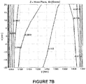
- the magnet field at 1m from isocenter 1C on the central plane CP there is a magnetic field of Bz ⁇ 0.1T, shown as point P1, which is a desired distance from isocenter for the source of the radiation of the linac 107.
- the magnetic field reverses direction from +Bz to -Bz at a radial distance of 0.81 m, shown as point P2.
- the magnet field at 1m from isocenter, where the linac 107 radiation source is preferrably located for optimal radiotherapy operation is low enough that it can be contained in a ferromagnetic shield or multiple layered shields, as described below.
- the central axial plane CP there is mainly axial magnetic field Bz because of coil symmetry.
- Y is a vertical axis and the axis of a high magnetic susceptibility (and/or permeability in a linear domain) material, e.g., a non-oriented silicon-steel shell, for shielding the linac 107.
- a high magnetic susceptibility (and/or permeability in a linear domain) material e.g., a non-oriented silicon-steel shell
- FIG. 2A The field generated by the main magnets 112a and 112b near the central plane CP is shown in Figure 2A .
- the linac 107 has a longitudinal axis ⁇ that is aligned with the Y-axis in Figure 1D . While the linac 107 is shown and described as being aligned along the Y-axis, it is rotatable about the Z-axis.
- the gantry 106 shown in Figures 1A and 1B can support the linac 107 and carry the linac 107 about the Z-axis (while the longitudinal axis ⁇ remains in the central plane CP), in the rotation directions RD shown in Figure 1D , such that the linac 107 can emit an electron beam EB towards the isocenter IC from any, or a range of, rotational positions about the Z-axis.
- the gantry 106 and linac 107 can rotate about the Z-axis independently of other components of the system 100.
- the gantry 106 and linac 107 can rotate independently of the MRI 102.
- a magnetic shield or shell 118 made of high magnetic susceptibility and permeability material, is placed around the linac accelerating structure 107.
- the shell 118 can be cylindrical in shape and aligned along axis ⁇ of the linac 107, with one or both ends of the shell 118 being open. While a cylindrical shape is preferred, the disclosed shield shells can be other shapes.
- the magnetic shield 118 can have a thickness chosen according to characteristics of the shell material.
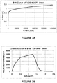
- the magnetic shield 118 (as well as other magnetic shields disclosed herein) can be formed of non-oriented silicon steel, for example a nickel-iron alloy, such as commercially-available material sold by ThyssenKrupp Steel under the trade name 530-50 AP and having a thickness of, for example, about be 5mm.
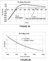
- the B-H curve and relative permeability of "530-50AP" material are shown in Figures 3A and 3B , respectively.
- Other material options for the magnetic shield 118 include M19 steel, M45 steel, and Carpenter High Permeability "49" Steel.
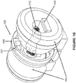
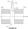
- the magnets 112a and 112b, and the location of the magnetic shield 118, are illustrated in Figure 4A , while a close-up perspective view of the magnetic shield 118 and linac 107 are shown in Figure 4B .
- the outer diameter OD and length L of the magnetic shield 118 can vary; in the present example, the outer diameter OD is about 30 cm, and the length L is about 70 cm.
- a bottom edge 118A of the magnetic shield 118 is located at a fixed distance from the isocenter IC (in the present example, about 80cm) that is at or near the Bz field reversal location, although this is not a requirement.
- the location and size of the magnetic shield 118 should be large enough to contain the linac 107, but not so long or narrow that it limits the size of the beam emitted by the linac 107.
- the magnetic shield 118 configuration is optimal for radiotherapy applications when combined with split main magnets 112a and 112b and gradient coil set, as the magnetic shield 118 is not imposed between the radiation source of the linac 107 and the patient 110. This allows for producing radiotherapy beams of the linac 107 of high quality and strength.
- the magnetic shielding is provided by multiple shield shells.
- the magnetic shielding is provided by the magnetic shield 118 and a second magnetic shield 120, where the shields 118 and 120 can be concentric layers of steel, which can be separated by layers of air or other insulating material.
- Figure 5A shows a comparison of the Bz-field generated by the main magnets 112a and 112b, and the z-component of the Bz-field generated by the main magnets 112a and 112b as shielded by the magnetic shielding comprising an outer magnetic shield 118 and an inner magnetic shield 120, where the shields 118 and 120 are separated by a layer of air.
- Table 1 lists the materials and dimensions of the magnetic shields 118 and 120 associated with Figures 5A and 5B .
- ID is the inner diameter
- OD is the outer diameter
- Length is the shell length L
- the "Starting Y-position” is the distance from the isocenter (Z-axis) to the respective bottom edges of the shields 118 and 120.
- the residual magnetic field along the axis of a single 5mm thick shell is about 4.5G, approximately ten times greater that the earth's magnetic field and larger than optimal for the linac 107.
- a secondary shielding element 120 inside of the magnetic shield 118 is added to further reduce the magnetic field.
- the secondary shielding element 120 is provided in the form of a second shell 120 positioned inside of the first shell 118, where both shells are coaxial along the longitudinal axis ⁇ of the linac 107.
- the second shell 120 is of higher permeability, but of a lower saturation flux density than the outer shell 118, as the outer shell 118 has greatly reduced the magnetic field, e.g., mu-metal. It is preferable to magnetically isolate the shells 118 and 120 in order to gain the highest shielding by restarting the saturation of the metal.
- the secondary shielding element 120 can be a current carrying coil that is located inside of the primary shell 118 to cancel the residual field. If the magnetic field remaining is sufficiently low and its value and direction in space are known, then it can be possible to make small adjustments in the accelerating portion of the linac
- the current linacs are configured to accommodate an electron beam that is at least substantially straight; if the beam were bent only a small amount by the field, the anticipated beam path can be calculated and the accelerating plates can be altered to accommodate the beam bending. Given the azimuthally symmetric nature of the fringe field, the path deviation of the electron beam should be largely independent of gantry position.
- the secondary shielding element 120 can be an RF shield 120, as further described below.
- the peak-to-peak field in-homogeneity of the system main magnets 112a and 112b plus the double shell is 623.8ppm over 45cm DSV. This inhomogeneity is too large for MRI system 102, so additional shimming is desirable.
- the field inhomogeneity is mostly represented by a few of the tesseral harmonics; S 1,1 ⁇ Y, C 2,2 ⁇ (X2-Y2), and S 3,1 ⁇ Z2X, and S 3,3 ⁇ X3. All of the major harmonics of significance are listed in Table 2.
- the zonal harmonics can all be handled by shimming, and the shim setting does not change with rotation of the linac 107 around the Z-axis. Hence, the shims can be located on the MRI bore.
- the negative of the zonal harmonics could even be built into the magnets 112a and 112b so that the combination of magnets 112a, 112b plus magnetic shield 118 eliminates these terms.
- the tesseral harmonics are a larger problem because they would move with the linac orientation.
- the tesseral harmonics could be shimmed out with passive shims near the central plane CP on the gantry 106 that would move with the gantry 106 / linac 107 rotation and/or with resistive shims built into the gradient coil that could be electrically adjusted to match the rotation of the gantry 106.
- the system 100 as shown in Figures 1A-1D includes a linac 107 having a vertical acceleration axis and is mounted on the gantry 106 so that the linac 107 can be rotated about the radiotherapy and MRI 102 isocenters.
- the linac 107 is also preferred to be of low energy, in the range of 4 to 6 MV, and have a standing wave guide to keep it compact.
- the linac 107 can be configured to only produce photon beams that can be used for intensity modulated radiation therapy or conformal radiation therapy.
- the linac 107 can operate at either S-band or X-Band frequencies, but S-band is preferred for high output and stability.
- the element 120 can be configured to serve as an RF shield 120.
- the RF shield shell 120 can be made of a suitable shielding material, for example copper foil, aluminum foil, or carbon fiber.
- a suitable shielding material for example copper foil, aluminum foil, or carbon fiber.
- Metals such as copper and aluminum tend to reflect RF radiation due to eddy currents on their surfaces.
- the carbon fiber materials tend to absorb RF energy.
- the eddy currents can be reduced by providing one or more slots that extend through the shield shell.
- shield shell 120 is shown as having slots 120A and 120B in Figure 4C .
- the size, number, and configuration of the slots can vary from that shown in Figure 4C .
- shield shell 120 is shown with slots, such slots can also, or alternatively, be provided in shield shell 118; also, any number of such slots can be provided in any one or more of the shield shells in examples having more than one shield shell.
- Such slots can also be desirable in the magnetic shielding shells, and can thus be included in some examples of the magnetic shielding shells.
- FIG. 4C shows two layers (shield shells 120 and 118), alternative examples can include any number of layers.
- the layers of shield shells can be made of combinations of different materials or of the same material.
- the shield shell layers can include alternating layers formed of RF absorbing material and RF reflecting material. In such examples, it is desirable to provide an air gap between the layers of shield shells.
- Cooling can be provided by cooling system 115 ( Figure IE) as needed to the absorbing material in the RF shield 120.
- the cooling system 115 can include, for example, fluid-carrying conduit for circulating a fluid in the vicinity of one or more of the shield shells that form the RF shield 120.
- air-cooling can be provided by incorporating a system for moving air across one or more surfaces of the shield shells that form the RF shield 120.
- the magnetic shield 118 and the RF shield 120 are placed around the linac 107 to shield the path of the electrons from the electron gun 107b of the linac 107 to the target to a magnetic field strength on the order of the size of the earth's magnetic field strength.
- the magnetic shield 118 is arranged such that it is not in the path of the radiotherapy beam, for example as shown in Figures 4A and 4C .
- the RF shield 120 is also placed around the linac 107, rather than the MRI 102, and comprised of both absorptive and reflective layers to dissipate and absorb the RF radiation generated by the linac 107 before it can compromise the MRI function and they can function as part of the flattening filter.
- the RF shield 120 can work in concert with a standard bore-mounted MRI RF shield.
- the beam from the linac 107 is allowed to pass through the RF shield 120 (as well as the bore mounted MRI RF shield) as long as the RF shield(s) are uniformly and minimally attenuating to the radiotherapy beam.
- the RF shield 120 can be provided without the magnetic shield 118 where only the RF shielding may be desired.
- the secondary shielding element 120 shown in Figure 4C is a second magnetic shield 120.
- a magnetic shield device 122 can include more concentric magnetic shields, i.e. magnetic shields 118 and 120 as well as one or more additional magnetic shields.
- the magnetic shield device 122 includes shields 118 and 120, that arc made of high magnetic susceptibility (and permeability) material.
- the shields of the magnetic shield device 122 are concentrically placed inside of each other around the linac 107 accelerating structure.
- the magnetic shields of the magnetic shield device 122 can be magnetically and electrically isolated from each other with a suitable dielectric material such as air or plastic. Having multiple magnetic shields is beneficial because the magnetic field shielding of the material begins to saturate with depth. Introducing a new magnetic shield restarts the saturation effect providing increased shielding. Also, some embodiments such as the one shown in Figure 4E can include a linac 107 having a split radiotherapy magnets 126 and 128 and a magnetic shield made of two isolated shells 130 and 132. The thickness of the magnetic shields shown in Figures 4A-4E can be chosen to be, for example, 5 mm, and the material can be selected to be 530-50AP steel material.
- the magnetic shield 118 (as well as other magnetic shields disclosed herein) include M19 steel, M45 steel, and steel sold by ThyssenKrupp Steel under the trade name 530-50 AP.
- the outer diameter OD and length L of the shielding shells can be, for example, 27cm and 30cm, respectively, in a two-shell configuration such as the one shown in Figure 4C .
- the shells 118 and 120 can both be located at a fixed distance from the isocenter IC (in the present example, about 85cm) that is at or near the Bz field reversal location, although this is not a requirement.
- the location and size of the magnetic shields should be large enough to contain the linac 107, but not so long or narrow that it limits the size of the beam from the linac 107.
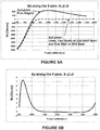
- Figure 6A shows a comparison of the Bz-field generated by the main magnets 112a and 112b, and the z-component of the Bz-field generated by the magnets 112a and 112b as shielded using a magnetic shield device 122 that includes three concentric shield shells.
- Table 3 lists the materials and dimensions of the magnetic shield device 122 according to Figures 6A and 6B .
- the magnetic shield device 122 includes three concentric shells separated from each other by layers of air.
- the shells of the shield device are preferrably cylindrical, but can be other shapes.
- ID is the inner diameter
- OD is the outer diameter
- Length is the shell length L
- Starting Y-position is the distance from the isocenter (Z-axis) to the respective bottom edges of the layers of the shield device 122.
- the residual B-field is less than 1 Gauss in the region 1100mm ⁇ y ⁇ 1400mm. This is roughly comparable to the earth's field close to the axis ⁇ .
- the harmonics of the magnetic field are close to the single shell model associated with the example shown in Figure 4B .
- the Peak-to-Peak field in-homogeneity over 45cm DSV generated by the main magnets 112a and 112b plus the magnetic shields 118 and 120 is 623.6ppm. It is preferable to have the best shielding on the electron gun 107b of the linac 107 and less shielding can be applied to the target end of the accelerating structure. This field in-homogeneity is mostly represented by the y-harmonic.
- FIG. 8 another example will be described that can reduce field in-homogeneity caused by the presence of a linac shield, such as the shield 118 shown in Figures 4A and 4B .
- the example shown in Figure 8 can be similar to the examples shown in Figures 4A and 4B , and like components have retained the same element numbers; description of those components applies equally here, so the description is not repeated.
- the first shield 118 extends along a first longitudinal axis ⁇ 1 and a second shield 140 (which can optionally include a second linac 107') extends along a second longitudinal axis ⁇ 2 symmetrically 180° apart from the first longitudinal axis ⁇ 1 of the first magnetic shield 118.
- the second shield 140 can be formed of a magnetically shielding material, such as steel sold by ThyssenKrupp Steel under the trade name 530-50 AP, as described in connection with magnetic shield 118.
- a magnetically shielding material such as steel sold by ThyssenKrupp Steel under the trade name 530-50 AP, as described in connection with magnetic shield 118.
- Other material options for the magnetic shield 118 include M19 steel, M45 steel, and Carpenter 49 steel. If only a second symmetric shield 140 is present, this solution can be thought of as a symmetric shim for the primary shell 118.
- One or both of the magnetic shields 118 and 140 can be magnetic shield devices that include two or more concentric magnetic shield shells, such as shown in Figure 4C or Figure 4D .
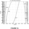
- Figure 9 shows the Bz-field generated by the main magnets 112a and 112b where both the magnetic shield 118 and the magnetic shield 140 include two concentric magnetic shielding shells.
- the peak-to-peak field in-homogeneity over 45cm DSV generated by the system main magnets 112a and 112b plus the two double-shell shield (118 + 140) is 416.96ppm.
- This field in-homogeneity is mostly generated by the Z2 harmonic.
- the Y-harmonics all become negligible small because of the Y symmetry.
- the harmonics for this case are listed in Table 4.
- the zonal harmonics are now twice as large as in the single shell model associated with the example shown in Figure 4B . However, they can all be handled by passive shimming, and the shim setting does not change with rotation of the linac 107 around the Z-axis.
- the negative of the zonal harmonics could even be built into the main magnets 112a and 112b so that the combination of main magnets 112a and 112b plus shield shells 118 and 140 eliminates these terms.
- the Tesseral harmonics are a larger problem because they would move with the linac 107 rotational position. However, symmetry eliminates the worst of the harmonics.
- the Tesseral harmonics can be shimmed out with passive shims near the central plane on the linac gantry 106 and/or with resistive electrical shims.
- Passive shims built into the rotating gantry 106 can be permanent magnet shims at these magnetic field levels (oriented magnetization shims for more shim options).
- Passive shims can be added at a smaller radius to reduce the material required in the shims. Resistive electrical shims in the gradient would change with the rotation of the linac gantry.
- N sets of magnetic shield shells identical or similar to magnetic shield 118 each having a respective axis ⁇ 1 through ⁇ N .
- Such examples can be arranged in a manner similar to Figure 8 .
- the magnetic shield shells tend to act as RF shields, multiple shells are advantageous for providing RF shielding.
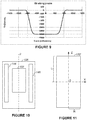
- annulus discs 144 and 146 there can be two parallel annulus discs 144 and 146 made of high relative permeability material. They can be a part of the gantry 106 and on opposing sides of the linac 107. In this case, the Tesseral spherical harmonics should be relatively small, and the Zonal harmonics should be relatively big. Placing two annulus discs 144 and 146 in some sense are equivalent to two extra coils in the main magnet 112a, 112b. Optimally, the main magnet 112a, 112b can be designed to accommodate two annulus discs 144 and 146.
- the magnetic field from the main magnets 112a and 112b at 1 meter from isocenter along the Y-axis is difficult to shield without the field reduction of passive shields, such as shield 118 described above.
- the residual field is near 5-7 Gauss.
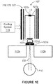
- This residual field can easily be shimmed out with DC current in a coil, for example in examples where the secondary shielding element 120 shown in Figure 4C is a coil 120'.
- a schematic view of the shielding coil 120' is shown in Figure 11 .
- the coil 120' can be cylindrical, having a half-length L and radius R and designed according to the following method (although shapes other than cylindrical can be used).
- the shielding coil 120' should preferrably produce the magnetic flux field Bx (in local system of coordinates) that cancels the Bz component of the magnetic field (in the original system of coordinates) generated by the main magnets 112a and 112b.
- a ⁇ ⁇ ⁇ z ⁇ R 2 2 ⁇ sin ⁇ ⁇ 0 ⁇ kdk T 2 k ⁇ R ⁇ T 0 k ⁇ R F S k z
- a ⁇ ⁇ ⁇ z ⁇ ⁇ R 2 2 ⁇ cos ⁇ ⁇ 0 ⁇ kdk T 2 k ⁇ R + T 0 k ⁇ R F S k z
- I n ( k ⁇ ), K n ( k ⁇ ) are modified Bessel functions.
- E is the energy of the coil 120'
- the second term is to minimize the deviation of the field produced by the shielding coil 120' from that of the main magnets 112a, 112b
- the third term is to minimize the effect of the shield coil 120' on the field in-homogeneity in the imaging volume
- the last term is introduced as to limit the current density.
- the coefficients ⁇ , ⁇ , and ⁇ are the weighting factors; ⁇ can be a rcgularization parameter to minimize the current in the shielding coil 120'.
- the current density f Z ( z ) can be expressed in terms of a basis functions. It should be mentioned that the current density f Z ( z ) is zero at the ends of the shielding coil 120'.
- the field produced by the shield coil 120' has the following form:
- Some examples can include a combined passive shield and active coil.
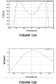
- the residual Bz-field shown in Figure 5b (a single shell case) was used as an input data.
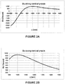
- Figure 12A shows the z-component of the current density on the active shield coil 120' prior to activation (i.e., prior to application of an electric current) of the coil 120'
- Figure 12B shows the residual Bz-field after activation of the shield coil 120'.
- the parameter ⁇ that accounts for the effect of correcting the in-homogeneity inside the DSV was chosen to be zero because the level of the residual field of Figure 5B is already small (of the order of 7Gauss) and the active shield coil is located far from the imaging volume.
- Some examples can include a completely active coil shielding system.
- the shielding of the linac 107 can be accomplished locally using only the above-described active current-carrying coils, such as coil 120', in place of the passive magnetic shields described above.
- the coils 120' can be arranged to simply cancel the field at the linac 107 and can also incorporate an active shield to reduce the influence on the homogeneity of the main magnetic field.
- Still another alternative way of shielding the linac 107 locally is to use a distribution of permanent magnets. They can be arranged to simply cancel the field at the linac 107 and can also incorporate an active shield, such as coil 120', to reduce the influence on the homogeneity of the main magnetic field from the main magnets 112a and 112b.
- the magnetic shields described herein such as shields 118, 120, 122, 130, 132, and others experience a force from the main magnets 112a and 112b of the MRI 102.
- the mounting for the shields is preferably designed to withstand such magnetic forces.
- the high-power RF source and waveguide for the linac 107 can also be enclosed, or partially enclosed, within the magnetic shields disclosed herein.
- the RF shielding can be extended to contain some or all components of the linac 107.
- clinical linacs suitable for use as linac 107 can operate in the S-band frequency range accelerate electrons to about 6MeV using RF microwave cavities at ⁇ 3GHz. While this frequency is well above the 15MHz of the MRI system 102, it involves megawatts of RF power pulse with a frequency of several hundred Hertz. Sidebands in the RF power source can excite/reflect from other materials causing interference with the operation of the MRI system 102.
- the element 120 can be an RF shield that is placed around the linac 107 made of RF absorbing, RF reflecting, or a combination of both can effectively eliminate the RF interference with the MRI system 102.
- the MRI RF room which can be made of RF reflecting material that can bound RF from the linac 107 into the MRI 102, can be lined on the interior surface with a wall covering of RF absorbing material, e.g., meshed or chopped carbon fiber, carbon fiber wallpaper, carbon fiber panels, or carbon fiber paint, and eliminate RF reaching the MRI.
- the gantry 106 and area around the RF source of the linac 107 can be covered in RF absorbers, reflectors, and combinations of both to reduce the ambient (environmental) RF fields.
- 3GHz microwave ovens arc at 2.45GHz
- the RF will produce dielectric heating of polarized molecules such as water.
- a variety of polarized molecule materials can be used as RF absorber for the RF energy.
- some of the conductive surfaces that divert RF energy in a closed system are missing in the magnet gap 114.
- An RF shield about the MRI bore can be used in conjunction with the other shielding method described above.
- the RF shields do not add significantly to the beam attenuation so that the quality of the radiotherapy is significantly compromised.
- the conductive shielding may or may not be grounded to the magnet. If these surfaces were made of aluminum, such as aluminum foil, the beam attenuation would even be less than using copper. If the gradient coil is wound on a former one can construct the former out of carbon fiber for isolation from the linac system.
Landscapes
- Physics & Mathematics (AREA)
- Health & Medical Sciences (AREA)
- Condensed Matter Physics & Semiconductors (AREA)
- General Physics & Mathematics (AREA)
- Engineering & Computer Science (AREA)
- Biomedical Technology (AREA)
- Nuclear Medicine, Radiotherapy & Molecular Imaging (AREA)
- General Health & Medical Sciences (AREA)
- Radiology & Medical Imaging (AREA)
- Epidemiology (AREA)
- Life Sciences & Earth Sciences (AREA)
- Veterinary Medicine (AREA)
- Pathology (AREA)
- Public Health (AREA)
- Animal Behavior & Ethology (AREA)
- High Energy & Nuclear Physics (AREA)
- Theoretical Computer Science (AREA)
- Pulmonology (AREA)
- Radiation-Therapy Devices (AREA)
- Magnetic Resonance Imaging Apparatus (AREA)
- Biophysics (AREA)
- Heart & Thoracic Surgery (AREA)
- Medical Informatics (AREA)
- Molecular Biology (AREA)
- Surgery (AREA)
- Particle Accelerators (AREA)
Applications Claiming Priority (2)
| Application Number | Priority Date | Filing Date | Title |
|---|---|---|---|
| US22577109P | 2009-07-15 | 2009-07-15 | |
| PCT/US2010/042156 WO2011008969A1 (en) | 2009-07-15 | 2010-07-15 | Method and apparatus for shielding a linear accelerator and a magnetic resonance imaging device from each other |
Publications (3)
| Publication Number | Publication Date |
|---|---|
| EP2454617A1 EP2454617A1 (en) | 2012-05-23 |
| EP2454617A4 EP2454617A4 (en) | 2013-11-20 |
| EP2454617B1 true EP2454617B1 (en) | 2021-01-06 |
Family
ID=43449796
Family Applications (1)
| Application Number | Title | Priority Date | Filing Date |
|---|---|---|---|
| EP10800553.9A Active EP2454617B1 (en) | 2009-07-15 | 2010-07-15 | Method and apparatus for shielding a linear accelerator and a magnetic resonance imaging device from each other |
Country Status (7)
| Country | Link |
|---|---|
| US (6) | US8836332B2 (enExample) |
| EP (1) | EP2454617B1 (enExample) |
| JP (6) | JP5719844B2 (enExample) |
| CN (3) | CN102472830B (enExample) |
| AU (4) | AU2010273298B2 (enExample) |
| CA (3) | CA3090069C (enExample) |
| WO (1) | WO2011008969A1 (enExample) |
Families Citing this family (104)
| Publication number | Priority date | Publication date | Assignee | Title |
|---|---|---|---|---|
| CA2749057A1 (en) | 2004-02-20 | 2005-09-09 | University Of Florida Research Foundation, Inc. | System for delivering conformal radiation therapy while simultaneously imaging soft tissue |
| CA2760053C (en) * | 2009-06-19 | 2020-02-11 | Viewray Technologies, Inc. | System and method for performing tomographic image acquisition and reconstruction |
| AU2010273298B2 (en) * | 2009-07-15 | 2014-10-23 | Viewray Technologies, Inc. | Method and apparatus for shielding a linear accelerator and a magnetic resonance imaging device from each other |
| DE102009038686B4 (de) * | 2009-08-24 | 2020-10-22 | Siemens Healthcare Gmbh | Ganzkörperspulenanordnung für eine offene Magnetresonanzeinrichtung zur Verwendung mit einer zweiten diagnostischen und/oder therapeutischen Modalität, Magnetresonanzeinrichtung und Kombinationseinrichtung |
| BR112012013588B1 (pt) * | 2009-12-02 | 2021-01-26 | Nanalysis Corp. | método para homogeneizar um campo magnético, detector para detectar a ressonância magnética e painel para homogeneizar um campo magnético |
| CN102781311B (zh) | 2010-02-24 | 2016-09-21 | 优瑞技术公司 | 分体式磁共振成像系统 |
| EP2558162B1 (en) * | 2010-04-15 | 2020-06-10 | Elekta AB (PUBL) | Radiotherapy and imaging apparatus |
| CN103260511B (zh) * | 2010-12-08 | 2015-12-16 | 皇家飞利浦电子股份有限公司 | 滑环组件 |
| DE102011006582A1 (de) | 2011-03-31 | 2012-10-04 | Siemens Aktiengesellschaft | Strahlentherapieanlage mit Hochfrequenzschirmung |
| CN102905619B (zh) * | 2011-05-10 | 2015-06-17 | 株式会社东芝 | 磁共振成像装置、磁共振成像装置用的磁场调整件、磁共振成像方法及磁共振成像装置的磁场调整方法 |
| WO2012164527A1 (en) * | 2011-05-31 | 2012-12-06 | Koninklijke Philips Electronics N.V. | Correcting the static magnetic field of an mri radiotherapy apparatus |
| US8981779B2 (en) | 2011-12-13 | 2015-03-17 | Viewray Incorporated | Active resistive shimming fro MRI devices |
| US10561861B2 (en) | 2012-05-02 | 2020-02-18 | Viewray Technologies, Inc. | Videographic display of real-time medical treatment |
| GB201217782D0 (en) * | 2012-10-04 | 2012-11-14 | Tesla Engineering Ltd | Magnet apparatus |
| US9889318B2 (en) | 2012-10-26 | 2018-02-13 | Viewray Technologies, Inc. | Assessment and improvement of treatment using imaging of physiological responses to radiation therapy |
| GB2507585B (en) | 2012-11-06 | 2015-04-22 | Siemens Plc | MRI magnet for radiation and particle therapy |
| GB2507792B (en) * | 2012-11-12 | 2015-07-01 | Siemens Plc | Combined MRI and radiation therapy system |
| TW201421211A (zh) * | 2012-11-16 | 2014-06-01 | 致伸科技股份有限公司 | 無線充電裝置 |
| KR101378447B1 (ko) | 2012-11-19 | 2014-03-26 | 한국전기연구원 | Mri 기반 linac 시스템을 위한 자기장 차폐 구조 |
| WO2014121991A1 (en) * | 2013-02-06 | 2014-08-14 | Koninklijke Philips N.V. | Active compensation for field distorting components in a magnetic resonance imaging system with a gantry |
| US9404983B2 (en) * | 2013-03-12 | 2016-08-02 | Viewray, Incorporated | Radio frequency transmit coil for magnetic resonance imaging system |
| US9675271B2 (en) * | 2013-03-13 | 2017-06-13 | Viewray Technologies, Inc. | Systems and methods for radiotherapy with magnetic resonance imaging |
| US9289626B2 (en) | 2013-03-13 | 2016-03-22 | Viewray Incorporated | Systems and methods for improved radioisotopic dose calculation and delivery |
| US9446263B2 (en) | 2013-03-15 | 2016-09-20 | Viewray Technologies, Inc. | Systems and methods for linear accelerator radiotherapy with magnetic resonance imaging |
| DE102013204952B3 (de) * | 2013-03-20 | 2014-05-15 | Bruker Biospin Ag | Aktiv abgeschirmtes zylinderförmiges Gradientenspulensystem mit passiver HF-Abschirmung für NMR-Apparate |
| JP6475234B2 (ja) * | 2013-06-21 | 2019-02-27 | コーニンクレッカ フィリップス エヌ ヴェKoninklijke Philips N.V. | 組み合わされた磁気共鳴イメージング及び放射線治療のためのクライオスタット及びシステム |
| WO2014203190A1 (en) * | 2013-06-21 | 2014-12-24 | Koninklijke Philips N.V. | Shim system for a magnetic resonance hybrid scanner |
| KR101545171B1 (ko) | 2013-09-23 | 2015-08-19 | 한국전기연구원 | 자기공명영상 유도 기반 선형가속기를 이용한 치료 시스템 |
| EP3052187B1 (en) | 2013-09-30 | 2018-11-14 | Koninklijke Philips N.V. | Alignment of the coordinate systems of external beam radiotherapy and magnetic resonance imaging systems |
| KR101540961B1 (ko) | 2013-10-15 | 2015-08-03 | 한국전기연구원 | 이동형 자기공명영상 장치를 이용한 방사선 치료 시스템 |
| KR101540977B1 (ko) | 2013-10-15 | 2015-08-03 | 한국전기연구원 | 분리가능형 자기공명영상 장치를 이용한 방사선 치료 시스템 |
| US10386432B2 (en) | 2013-12-18 | 2019-08-20 | Aspect Imaging Ltd. | Radiofrequency shielding conduit in a door or a doorframe of a magnetic resonance imaging room |
| US9661734B2 (en) | 2014-02-27 | 2017-05-23 | ETM Electromatic, Inc. | Linear accelerator system with stable interleaved and intermittent pulsing |
| WO2017100611A1 (en) * | 2015-12-09 | 2017-06-15 | ETM Electromatic, Inc. | Self-shielded image guided radiation oncology system |
| US10094720B2 (en) | 2014-04-10 | 2018-10-09 | General Electric Company | System and method of magnetic shielding for sensors |
| US9429488B2 (en) * | 2014-04-10 | 2016-08-30 | General Electric Company | System and method of magnetic shielding for sensors |
| RU2681075C2 (ru) * | 2014-06-27 | 2019-03-01 | Конинклейке Филипс Н.В. | Терапия пучками заряженных частиц и магнитно-резонансная томография |
| US10718831B2 (en) * | 2014-09-01 | 2020-07-21 | Koninklijke Philips N.V. | Magnetic resonance imaging receive coil with reduced radiation attenuation |
| US11045108B2 (en) * | 2014-11-26 | 2021-06-29 | Viewray Technologies, Inc. | Magnetic resonance imaging receive coil assembly |
| DE102014225111B4 (de) * | 2014-12-08 | 2021-04-15 | Siemens Healthcare Gmbh | Verfahren zum Vorbereiten eines Behandlungsraumes füreine Strahlentherapie |
| EP4325235A3 (en) | 2015-02-11 | 2024-05-22 | ViewRay Technologies, Inc. | Planning and control for magnetic resonance guided radiation therapy |
| US10252083B2 (en) * | 2015-09-23 | 2019-04-09 | Varian Medical Systems Inc. | Systems, methods, and devices for high-energy irradiation |
| US10610122B2 (en) * | 2015-09-29 | 2020-04-07 | Avraham Suhami | Linear velocity imaging tomography |
| CN105363138B (zh) * | 2015-12-07 | 2018-01-12 | 北京健联医疗科技有限公司 | 电子直线加速器和mri引导的x射线放疗机 |
| CN106918794B (zh) * | 2015-12-25 | 2021-01-08 | 上海联影医疗科技股份有限公司 | 磁共振系统及成像的方法 |
| SG10202104647WA (en) * | 2015-12-30 | 2021-06-29 | Syncardon Llc | Apparatus and method for promoting wound healing |
| EP3423153B1 (en) | 2016-03-02 | 2021-05-19 | ViewRay Technologies, Inc. | Particle therapy with magnetic resonance imaging |
| US9855445B2 (en) | 2016-04-01 | 2018-01-02 | Varian Medical Systems, Inc. | Radiation therapy systems and methods for delivering doses to a target volume |
| US11249156B2 (en) | 2016-04-25 | 2022-02-15 | Koninklijke Philips N.V. | Magnetic resonance radiation shield and shielded main magnet |
| US11378629B2 (en) | 2016-06-22 | 2022-07-05 | Viewray Technologies, Inc. | Magnetic resonance imaging |
| JP2019524301A (ja) * | 2016-08-08 | 2019-09-05 | コーニンクレッカ フィリップス エヌ ヴェKoninklijke Philips N.V. | モックアップアンテナ及びコイルシステム |
| EP3308834B1 (en) * | 2016-10-11 | 2019-01-09 | Ion Beam Applications | Particle therapy apparatus comprising an mri |
| EP3327457A1 (de) | 2016-11-23 | 2018-05-30 | Siemens Healthcare GmbH | Medizinisches bildgebungssystem umfassend eine magneteinheit und eine strahlungseinheit |
| RU2019121943A (ru) | 2016-12-13 | 2021-01-15 | Вьюрэй Текнолоджиз, Инк. | Системы и способы лучевой терапии |
| CN106621075B (zh) * | 2016-12-22 | 2021-01-08 | 上海联影医疗科技股份有限公司 | 放射治疗装置 |
| WO2018115223A1 (en) * | 2016-12-22 | 2018-06-28 | Koninklijke Philips N.V. | Rf coil device and rf shield device for different mri modes |
| CN106861055B (zh) * | 2016-12-30 | 2019-10-18 | 江苏海明医疗器械有限公司 | 一种通用机架的控制驱动系统 |
| CN106856654B (zh) * | 2017-03-13 | 2019-08-02 | 深圳市金石医疗科技有限公司 | 自屏蔽式磁共振装置 |
| KR101953350B1 (ko) * | 2017-06-23 | 2019-02-28 | 재단법인 아산사회복지재단 | 자기장과 산란체를 이용한 광자선의 선량상승영역 변조 장치, 이를 포함하는 광자선 기반의 방사선치료장치 및 자기장과 산란체를 이용한 광자선의 선량상승영역 변조 방법 |
| US10092774B1 (en) | 2017-07-21 | 2018-10-09 | Varian Medical Systems International, AG | Dose aspects of radiation therapy planning and treatment |
| US11712579B2 (en) | 2017-07-21 | 2023-08-01 | Varian Medical Systems, Inc. | Range compensators for radiation therapy |
| US10183179B1 (en) | 2017-07-21 | 2019-01-22 | Varian Medical Systems, Inc. | Triggered treatment systems and methods |
| US10549117B2 (en) | 2017-07-21 | 2020-02-04 | Varian Medical Systems, Inc | Geometric aspects of radiation therapy planning and treatment |
| US10843011B2 (en) | 2017-07-21 | 2020-11-24 | Varian Medical Systems, Inc. | Particle beam gun control systems and methods |
| US11590364B2 (en) | 2017-07-21 | 2023-02-28 | Varian Medical Systems International Ag | Material inserts for radiation therapy |
| EP3460500A1 (de) | 2017-09-26 | 2019-03-27 | Siemens Healthcare GmbH | Medizinisches bildgebungsgerät zur kombinierten magnetresonanzbildgebung und bestrahlung und verfahren zur bestimmung der bestückung von shim-einheiten |
| GB2567193A (en) * | 2017-10-05 | 2019-04-10 | Elekta ltd | Image guided radiation therapy apparatus |
| EP3710111B1 (en) | 2017-11-16 | 2021-12-29 | Varian Medical Systems, Inc. | Increased beam output and dynamic field shaping for radiotherapy system |
| CN107754099A (zh) * | 2017-11-27 | 2018-03-06 | 上海联影医疗科技有限公司 | 磁共振引导的放疗系统 |
| JP7127126B2 (ja) | 2017-12-06 | 2022-08-29 | ビューレイ・テクノロジーズ・インコーポレイテッド | 放射線治療のシステム、方法およびソフトウェア |
| CN110058184B (zh) * | 2018-01-19 | 2021-06-08 | 北京绪水互联科技有限公司 | 冷头效率的计算方法、及冷头效率的监测方法和系统 |
| CN108761365B (zh) | 2018-04-11 | 2021-02-19 | 上海联影医疗科技股份有限公司 | 屏蔽壳、屏蔽壳的制造方法、pet探测器和系统 |
| US11209509B2 (en) | 2018-05-16 | 2021-12-28 | Viewray Technologies, Inc. | Resistive electromagnet systems and methods |
| CN108671418A (zh) * | 2018-05-24 | 2018-10-19 | 中国科学院近代物理研究所 | 用于离子束放射治疗的磁共振图像引导装置 |
| GB2575637B (en) * | 2018-07-16 | 2022-06-29 | Elekta ltd | Radiotherapy apparatus |
| US10910188B2 (en) | 2018-07-25 | 2021-02-02 | Varian Medical Systems, Inc. | Radiation anode target systems and methods |
| CN111107900B (zh) | 2018-11-14 | 2022-03-04 | 上海联影医疗科技股份有限公司 | 放射治疗系统 |
| CN109499008B (zh) * | 2018-12-06 | 2024-11-29 | 佛山瑞加图医疗科技有限公司 | 一种用于磁共振引导的放疗设备的屏蔽装置 |
| CN109847194B (zh) * | 2018-12-29 | 2024-07-19 | 佛山瑞加图医疗科技有限公司 | 一种磁共振引导的放疗系统 |
| WO2020155137A1 (en) * | 2019-02-02 | 2020-08-06 | Shanghai United Imaging Healthcare Co., Ltd. | Radiation therapy system and method |
| US10814144B2 (en) | 2019-03-06 | 2020-10-27 | Varian Medical Systems, Inc. | Radiation treatment based on dose rate |
| GB2582009B (en) * | 2019-03-08 | 2021-04-07 | Siemens Healthcare Ltd | Split magnet with rotating central component |
| US10918886B2 (en) | 2019-06-10 | 2021-02-16 | Varian Medical Systems, Inc. | Flash therapy treatment planning and oncology information system having dose rate prescription and dose rate mapping |
| CN119701232A (zh) * | 2019-08-26 | 2025-03-28 | 上海联影医疗科技股份有限公司 | 放射治疗系统和方法 |
| US12390662B2 (en) | 2020-04-02 | 2025-08-19 | Siemens Healthineers International Ag | System and method for proton therapy treatment planning with proton energy and spot optimization |
| US11865361B2 (en) | 2020-04-03 | 2024-01-09 | Varian Medical Systems, Inc. | System and method for scanning pattern optimization for flash therapy treatment planning |
| US11754650B2 (en) * | 2020-04-10 | 2023-09-12 | Howmedica Osteonics Corp. | MRI shield |
| CN119733178A (zh) * | 2020-06-17 | 2025-04-01 | 上海联影医疗科技股份有限公司 | 一种放射治疗系统 |
| WO2021253251A1 (en) * | 2020-06-17 | 2021-12-23 | Shanghai United Imaging Healthcare Co., Ltd. | Radiation therapy devices and magnetic resonance guided radiation therapy systems |
| US11541252B2 (en) | 2020-06-23 | 2023-01-03 | Varian Medical Systems, Inc. | Defining dose rate for pencil beam scanning |
| US11957934B2 (en) | 2020-07-01 | 2024-04-16 | Siemens Healthineers International Ag | Methods and systems using modeling of crystalline materials for spot placement for radiation therapy |
| US12064645B2 (en) | 2020-07-02 | 2024-08-20 | Siemens Healthineers International Ag | Methods and systems used for planning radiation treatment |
| CN114504737B (zh) * | 2020-11-17 | 2025-07-22 | 上海联影医疗科技股份有限公司 | 磁共振引导的放射治疗系统及磁共振设备 |
| JP2024511277A (ja) | 2021-02-19 | 2024-03-13 | メビオン・メディカル・システムズ・インコーポレーテッド | 粒子線治療システムのためのガントリー |
| CN113171562B (zh) * | 2021-05-27 | 2025-05-06 | 北京雷泰腾飞医疗科技有限公司 | 多功能核磁装置、加速器放射治疗设备及其成像方法 |
| TWI836518B (zh) * | 2021-07-20 | 2024-03-21 | 美商美威高能離子醫療系統公司 | 粒子治療系統及用於其之檯座 |
| CN117980036A (zh) * | 2021-07-20 | 2024-05-03 | 美国迈胜医疗系统有限公司 | 具有可缩回盖的机架 |
| US12025684B2 (en) | 2021-08-04 | 2024-07-02 | Viewray Systems, Inc. | RF coil assemblies |
| CN115770359B (zh) * | 2021-09-06 | 2025-09-23 | 上海联影医疗科技股份有限公司 | 医学设备孔径结构、设备和放射治疗系统 |
| JP7739113B2 (ja) * | 2021-09-29 | 2025-09-16 | 株式会社日立ハイテク | 放射線治療システム、および、放射線治療システムの運転方法 |
| US12478803B2 (en) | 2021-10-22 | 2025-11-25 | Viewray Systems, Inc. | Systems, methods and computer software for optimized radiation therapy |
| US12350523B2 (en) | 2021-10-22 | 2025-07-08 | Viewray Systems, Inc. | MRI guided radiotherapy |
| WO2023108445A1 (en) * | 2021-12-14 | 2023-06-22 | Shanghai United Imaging Healthcare Co., Ltd. | Radiation therapy system and method |
| CN115923639A (zh) * | 2022-12-28 | 2023-04-07 | 吉林省百皓科技有限公司 | 一种车载箱式高能电子加速器装备电子束辐照车厢 |
Family Cites Families (167)
| Publication number | Priority date | Publication date | Assignee | Title |
|---|---|---|---|---|
| US3569823A (en) | 1968-10-18 | 1971-03-09 | Perkin Elmer Corp | Nuclear magnetic resonance apparatus |
| US3735306A (en) | 1970-10-22 | 1973-05-22 | Varian Associates | Magnetic field shim coil structure utilizing laminated printed circuit sheets |
| JPS59147061A (ja) | 1983-02-14 | 1984-08-23 | Nissan Motor Co Ltd | 燃料タンク用防錆剤 |
| US4581580A (en) | 1983-12-14 | 1986-04-08 | General Electric Company | Intentionally non-orthogonal correction coils for high-homogeneity magnets |
| US4642569A (en) | 1983-12-16 | 1987-02-10 | General Electric Company | Shield for decoupling RF and gradient coils in an NMR apparatus |
| JPS60189905A (ja) | 1984-03-09 | 1985-09-27 | Mitsubishi Electric Corp | 高均一磁界発生装置 |
| JPS6224020U (enExample) | 1985-07-26 | 1987-02-13 | ||
| US4740753A (en) | 1986-01-03 | 1988-04-26 | General Electric Company | Magnet shimming using information derived from chemical shift imaging |
| US5006804A (en) | 1989-12-04 | 1991-04-09 | General Electric Company | Method of optimizing shim coil current selection in magnetic resonance magnets |
| US5621324A (en) * | 1992-03-18 | 1997-04-15 | Sumitomo Special Metals Company Limited | Magnetic field generator for MRI |
| US5382904A (en) * | 1992-04-15 | 1995-01-17 | Houston Advanced Research Center | Structured coil electromagnets for magnetic resonance imaging and method for fabricating the same |
| DE4217496C2 (de) * | 1992-05-27 | 1994-06-16 | Bruker Analytische Messtechnik | Shim-Verfahren |
| US5280428A (en) * | 1992-07-14 | 1994-01-18 | General Electric Company | Method and apparatus for projecting diagnostic images from volumed diagnostic data accessed in data tubes |
| US5331552A (en) * | 1992-07-14 | 1994-07-19 | General Electric Company | Method and apparatus for projecting diagnostic images from non-isotropic volumed diagnostic data |
| US5295488A (en) * | 1992-08-05 | 1994-03-22 | General Electric Company | Method and apparatus for projecting diagnostic images from volumed diagnostic data |
| US5760582A (en) | 1992-07-23 | 1998-06-02 | Fonar Corporation | Optimized gradient coils and shim coils for magnetic resonance scanning systems |
| US5361763A (en) * | 1993-03-02 | 1994-11-08 | Wisconsin Alumni Research Foundation | Method for segmenting features in an image |
| DE4333440C1 (de) | 1993-09-30 | 1995-04-06 | Siemens Ag | Verfahren zur Shimmung eines Magnetfeldes in einem Untersuchungsraum eines Kernspinresonanzgerätes |
| US5365927A (en) | 1993-11-02 | 1994-11-22 | General Electric Company | Magnetic resonance imaging system with pointing device |
| US5378989A (en) | 1993-11-02 | 1995-01-03 | General Electric Company | Open gradient coils for magnetic resonance imaging |
| DE4437443C2 (de) | 1994-10-19 | 1996-09-12 | Siemens Ag | Verfahren zum Betrieb eines Kernspintomographiegerätes mit dynamisch lokalisierter Shimmung des Grundmagnetfeldes |
| US5585724A (en) | 1995-06-12 | 1996-12-17 | Picker International, Inc. | Magnetic resonance gradient coils with interstitial gap |
| US5675305A (en) * | 1996-07-17 | 1997-10-07 | Picker International, Inc. | Multiple driven C magnet |
| US5851182A (en) * | 1996-09-11 | 1998-12-22 | Sahadevan; Velayudhan | Megavoltage radiation therapy machine combined to diagnostic imaging devices for cost efficient conventional and 3D conformal radiation therapy with on-line Isodose port and diagnostic radiology |
| US6157278A (en) * | 1997-07-23 | 2000-12-05 | Odin Technologies Ltd. | Hybrid magnetic apparatus for use in medical applications |
| US6198957B1 (en) * | 1997-12-19 | 2001-03-06 | Varian, Inc. | Radiotherapy machine including magnetic resonance imaging system |
| US5952830A (en) | 1997-12-22 | 1999-09-14 | Picker International, Inc. | Octapole magnetic resonance gradient coil system with elongate azimuthal gap |
| US6311389B1 (en) | 1998-07-01 | 2001-11-06 | Kabushiki Kaisha Toshiba | Gradient magnetic coil apparatus and method of manufacturing the same |
| US6591127B1 (en) | 1999-03-15 | 2003-07-08 | General Electric Company | Integrated multi-modality imaging system and method |
| DE19959720B4 (de) | 1999-12-10 | 2005-02-24 | Siemens Ag | Verfahren zum Betrieb eines Magnetresonanztomographiegeräts |
| US6556012B2 (en) * | 2000-01-21 | 2003-04-29 | Kabushiki Kaisha Toshiba | Magnetic resonance imaging apparatus |
| US6954068B1 (en) * | 2000-01-21 | 2005-10-11 | Kabushiki Kaisha Toshiba | Magnetic resonance imaging apparatus |
| US6567685B2 (en) * | 2000-01-21 | 2003-05-20 | Kabushiki Kaisha Toshiba | Magnetic resonance imaging apparatus |
| DE10006317C1 (de) * | 2000-02-12 | 2001-08-16 | Bruker Ag Faellanden | Gekühlter NMR-Probenkopf mit thermischer Isolation der Meßprobe |
| GB0007018D0 (en) * | 2000-03-22 | 2000-05-10 | Akguen Ali | Magnetic resonance imaging apparatus and method |
| US6564084B2 (en) * | 2001-03-02 | 2003-05-13 | Draeger Medical, Inc. | Magnetic field shielding and detecting device and method thereof |
| JP2003024296A (ja) | 2001-07-04 | 2003-01-28 | Ge Medical Systems Global Technology Co Llc | 静磁界調整方法およびmri装置 |
| GB2382512A (en) * | 2001-07-20 | 2003-05-28 | Elekta Oncology Syst Ltd | MRI in guided radiotherapy and position verification |
| US6626264B1 (en) * | 2001-10-30 | 2003-09-30 | Igt | Radio frequency shielded and acoustically insulated enclosure |
| US6664879B2 (en) * | 2001-12-04 | 2003-12-16 | Nmr Holdings No. 2 Pty Limited | Asymmetric tesseral shim coils for magnetic resonance |
| US6657391B2 (en) * | 2002-02-07 | 2003-12-02 | Siemens Medical Solutions Usa, Inc. | Apparatus and method for establishing a Q-factor of a cavity for an accelerator |
| US6630829B1 (en) | 2002-04-22 | 2003-10-07 | Ge Medical Systems Global Technology Co., Llc | Gradient coil set capable of producing a variable field of view |
| US7162005B2 (en) * | 2002-07-19 | 2007-01-09 | Varian Medical Systems Technologies, Inc. | Radiation sources and compact radiation scanning systems |
| GB2393373A (en) * | 2002-09-13 | 2004-03-24 | Elekta Ab | MRI in guided radiotherapy and position verification |
| AU2003272029A1 (en) | 2002-11-20 | 2004-06-15 | Koninklijke Philips Electronics N.V. | Self-shielded gradient field coil for magnetic resonance imaging |
| US7317782B2 (en) * | 2003-01-31 | 2008-01-08 | Varian Medical Systems Technologies, Inc. | Radiation scanning of cargo conveyances at seaports and the like |
| GB2401946B (en) | 2003-03-25 | 2006-10-04 | Siemens Ag | Generator for time-variable magnetic fields of a magnetic resonance instrument and magnetic resonance instrument with the generator |
| US6788060B1 (en) | 2003-05-28 | 2004-09-07 | Ge Medical Systems Global Technology Co., Inc. | Imaging system with homogeneous magnetic field |
| US7015692B2 (en) | 2003-08-07 | 2006-03-21 | Ge Electric Company | Apparatus for active cooling of an MRI patient bore in cylindrical MRI systems |
| US7053617B2 (en) * | 2003-10-01 | 2006-05-30 | General Electric Co. | Integrated electronic RF shielding apparatus for an MRI magnet |
| US6906606B2 (en) * | 2003-10-10 | 2005-06-14 | General Electric Company | Magnetic materials, passive shims and magnetic resonance imaging systems |
| WO2005058385A2 (en) | 2003-12-12 | 2005-06-30 | Philometron, Inc. | Multiple section parenteral drug delivery apparatus |
| GB2409521B (en) | 2003-12-22 | 2007-04-18 | Ge Med Sys Global Tech Co Llc | Gradient coil apparatus and method of assembly thereof |
| US7853308B2 (en) * | 2004-02-17 | 2010-12-14 | Siemens Medical Solutions Usa, Inc. | System and method for patient positioning for radiotherapy in the presence of respiratory motion |
| CA2749057A1 (en) | 2004-02-20 | 2005-09-09 | University Of Florida Research Foundation, Inc. | System for delivering conformal radiation therapy while simultaneously imaging soft tissue |
| US7372271B2 (en) * | 2004-03-15 | 2008-05-13 | Koninklijke Philips Electronics N. V. | Main magnet perforated eddy current shield for a magnetic resonance imaging device |
| JP4392280B2 (ja) | 2004-03-26 | 2009-12-24 | 株式会社日立製作所 | 放射性同位元素製造装置および放射性薬剤製造装置 |
| ITSV20040016A1 (it) * | 2004-04-13 | 2004-07-13 | Esaote Spa | Macchina per risonanza magnetico nucleare |
| US20050236588A1 (en) * | 2004-04-21 | 2005-10-27 | Moshe Ein-Gal | Radiation shield capsule |
| US20080049897A1 (en) | 2004-05-24 | 2008-02-28 | Molloy Janelle A | System and Method for Temporally Precise Intensity Modulated Radiation Therapy (Imrt) |
| US20060017411A1 (en) * | 2004-06-17 | 2006-01-26 | Accsys Technology, Inc. | Mobile/transportable PET radioisotope system with omnidirectional self-shielding |
| US7012385B1 (en) * | 2004-09-24 | 2006-03-14 | Viara Research, Llc | Multi-channel induction accelerator with external channels |
| WO2006047580A2 (en) * | 2004-10-26 | 2006-05-04 | Univ California | System and method for providing a rotating magnetic field |
| US7957507B2 (en) | 2005-02-28 | 2011-06-07 | Cadman Patrick F | Method and apparatus for modulating a radiation beam |
| WO2006097864A1 (en) | 2005-03-17 | 2006-09-21 | Koninklijke Philips Electronics, N.V. | Minimum energy shim coils for magnetic resonance |
| US7640607B2 (en) * | 2005-04-29 | 2010-01-05 | Varian Medical Systems, Inc. | Patient support systems |
| US20070016014A1 (en) * | 2005-06-15 | 2007-01-18 | Kenji Hara | Radio therapy apparatus and operating method of the same |
| IES20050529A2 (en) * | 2005-08-12 | 2007-01-10 | Ray Lawless | Moveable support |
| JP4386288B2 (ja) | 2005-08-31 | 2009-12-16 | 株式会社日立製作所 | 放射線治療装置の位置決めシステム及び位置決め方法 |
| EP1760481B1 (en) * | 2005-09-03 | 2010-05-19 | Bruker BioSpin AG | Matrix shim system with grouped coils |
| US7295649B2 (en) | 2005-10-13 | 2007-11-13 | Varian Medical Systems Technologies, Inc. | Radiation therapy system and method of using the same |
| US8073102B2 (en) * | 2005-10-17 | 2011-12-06 | Alberta Health Services | Real-time dose reconstruction using dynamic simulation and image guided adaptive radiotherapy |
| US9468777B2 (en) * | 2005-10-17 | 2016-10-18 | Alberta Health Services | Integrated external beam radiotherapy and MRI system |
| ES2730108T3 (es) * | 2005-11-18 | 2019-11-08 | Mevion Medical Systems Inc | Radioterapia de partículas cargadas |
| EP1818078A1 (en) | 2006-02-09 | 2007-08-15 | DKFZ Deutsches Krebsforschungszentrum | Inverse treatment planning method |
| WO2007126782A2 (en) | 2006-03-28 | 2007-11-08 | Hampton University | Hadron treatment planning with adequate biological weighting |
| US7557575B2 (en) * | 2006-04-04 | 2009-07-07 | Kabushiki Kaisha Toshiba | Magnetic resonance imaging apparatus and magnetic resonance imaging method |
| US7902530B1 (en) | 2006-04-06 | 2011-03-08 | Velayudhan Sahadevan | Multiple medical accelerators and a kV-CT incorporated radiation therapy device and semi-automated custom reshapeable blocks for all field synchronous image guided 3-D-conformal-intensity modulated radiation therapy |
| US7605589B2 (en) | 2006-04-10 | 2009-10-20 | Bruker Biospin Ag | Method for automatic shimming for nuclear magnetic resonance spectroscopy |
| US20080023010A1 (en) * | 2006-07-27 | 2008-01-31 | Cyberonics, Inc. | RF Shielding In MRI For Safety Of Implantable Medical Devices |
| US7505559B2 (en) | 2006-08-25 | 2009-03-17 | Accuray Incorporated | Determining a target-to-surface distance and using it for real time absorbed dose calculation and compensation |
| US7589531B2 (en) * | 2007-01-17 | 2009-09-15 | Kabushiki Kaisha Toshiba | Gradient magnetic field coil unit, gantry for MRI apparatus, and MRI apparatus |
| JP5209277B2 (ja) * | 2007-01-17 | 2013-06-12 | 株式会社東芝 | 傾斜磁場コイルユニット、mri装置用ガントリ、及びmri装置 |
| US8460195B2 (en) * | 2007-01-19 | 2013-06-11 | Sunnybrook Health Sciences Centre | Scanning mechanisms for imaging probe |
| CN101686827B (zh) * | 2007-01-19 | 2014-08-13 | 桑尼布鲁克健康科学中心 | 具有组合的超声和光学成像装置的成像探头 |
| DE102008007245B4 (de) * | 2007-02-28 | 2010-10-14 | Siemens Aktiengesellschaft | Kombiniertes Strahlentherapie- und Magnetresonanzgerät |
| BRPI0809689B1 (pt) | 2007-04-04 | 2019-03-19 | Koninklijke Philips N.V. | Bobina de gradiente de campo magnético, escâner por ressonância magnética, e, escâner híbrido |
| US7489131B2 (en) | 2007-04-23 | 2009-02-10 | General Electric Co. | System and apparatus for direct cooling of gradient coils |
| US7898192B2 (en) | 2007-06-06 | 2011-03-01 | Siemens Medical Solutions Usa, Inc. | Modular linac and systems to support same |
| EP2176683B1 (en) | 2007-07-02 | 2017-08-09 | Koninklijke Philips N.V. | Thermally stabilized pet detector for hybrid pet-mr system |
| US8570042B2 (en) * | 2007-08-31 | 2013-10-29 | The Regents Of The University Of California | Adjustable permanent magnet assembly for NMR and MRI |
| CN101452065B (zh) | 2007-12-04 | 2011-10-19 | 西门子(中国)有限公司 | 磁共振设备中的局部线圈、磁共振设备以及成像方法 |
| JP5390539B2 (ja) | 2008-02-25 | 2014-01-15 | コーニンクレッカ フィリップス エヌ ヴェ | 放射線検出器に対する等角面のバックボーン |
| US20110118588A1 (en) * | 2008-03-12 | 2011-05-19 | Giora Komblau | Combination MRI and Radiotherapy Systems and Methods of Use |
| US7741624B1 (en) * | 2008-05-03 | 2010-06-22 | Velayudhan Sahadevan | Single session interactive ultra-short duration super-high biological dose rate radiation therapy and radiosurgery |
| WO2009142548A2 (en) | 2008-05-22 | 2009-11-26 | Vladimir Yegorovich Balakin | X-ray method and apparatus used in conjunction with a charged particle cancer therapy system |
| WO2009155700A1 (en) | 2008-06-24 | 2009-12-30 | Marco Carlone | Radiation therapy system |
| CA2638996C (en) * | 2008-08-20 | 2013-04-30 | Imris Inc. | Mri guided radiation therapy |
| EP2196240A1 (en) | 2008-12-12 | 2010-06-16 | Koninklijke Philips Electronics N.V. | Therapeutic apparatus |
| DE112008004206B4 (de) | 2008-12-24 | 2013-06-20 | Mitsubishi Electric Corp. | Teilchenstrahl-Therapiesystem mit Bestätigung der Formgebung eines variablen Kollimators auch während eines Bestrahlungsvorganges |
| JP5224421B2 (ja) | 2009-03-12 | 2013-07-03 | 独立行政法人放射線医学総合研究所 | オープンpet/mri複合機 |
| US8331531B2 (en) * | 2009-03-13 | 2012-12-11 | The Board Of Trustees Of The Leland Stanford Junior University | Configurations for integrated MRI-linear accelerators |
| EP2230530A1 (en) | 2009-03-20 | 2010-09-22 | Koninklijke Philips Electronics N.V. | A tesseral shim coil for a magnetic resonance system |
| CA2760053C (en) | 2009-06-19 | 2020-02-11 | Viewray Technologies, Inc. | System and method for performing tomographic image acquisition and reconstruction |
| US8139714B1 (en) * | 2009-06-25 | 2012-03-20 | Velayudhan Sahadevan | Few seconds beam on time, breathing synchronized image guided all fields simultaneous radiation therapy combined with hyperthermia |
| AU2010273298B2 (en) | 2009-07-15 | 2014-10-23 | Viewray Technologies, Inc. | Method and apparatus for shielding a linear accelerator and a magnetic resonance imaging device from each other |
| DE102009035951B4 (de) | 2009-08-03 | 2018-02-22 | Siemens Healthcare Gmbh | Bestimmung von Strahlparametern für asymmetrische Photonenstrahlen |
| JP5732065B2 (ja) | 2009-11-20 | 2015-06-10 | ビューレイ・インコーポレイテッドViewRay Incorporated | 自己遮蔽型傾斜コイル |
| US8173983B1 (en) | 2010-01-07 | 2012-05-08 | Velayudhan Sahadevan | All field simultaneous radiation therapy |
| US9694205B2 (en) | 2010-02-12 | 2017-07-04 | Elekta Ab (Publ) | Radiotherapy and imaging apparatus |
| CN102781311B (zh) | 2010-02-24 | 2016-09-21 | 优瑞技术公司 | 分体式磁共振成像系统 |
| US8710843B2 (en) * | 2010-04-27 | 2014-04-29 | University Health Network | Magnetic resonance imaging apparatus for use with radiotherapy |
| CN102939607B (zh) | 2010-06-11 | 2016-05-18 | 皇家飞利浦电子股份有限公司 | 针对放射治疗处置规划的同时多模态逆向优化的系统、方法和装置 |
| EP2400314A1 (en) * | 2010-06-14 | 2011-12-28 | Agilent Technologies U.K. Limited | Superconducting magnet arrangement and method of mounting thereof |
| DE102010032080B4 (de) * | 2010-07-23 | 2012-09-27 | Siemens Aktiengesellschaft | Getriggerte Magnetresonanzbildgebung auf der Grundlage einer partiellen parallelen Akquisition (PPA) |
| EP2638409B1 (en) * | 2010-11-09 | 2020-01-08 | Koninklijke Philips N.V. | Magnetic resonance imaging and radiotherapy apparatus with at least two-transmit-and receive channels |
| CN103260700B (zh) | 2010-12-13 | 2016-06-15 | 皇家飞利浦电子股份有限公司 | 包括辐射治疗设备、机械定位系统和磁共振成像系统的治疗设备 |
| EP2654574B1 (en) * | 2010-12-22 | 2017-05-03 | ViewRay Technologies, Inc. | System and method for image guidance during medical procedures |
| US8565377B2 (en) | 2011-03-07 | 2013-10-22 | Dalhousie University | Methods and apparatus for imaging in conjunction with radiotherapy |
| EP2500909A1 (en) | 2011-03-16 | 2012-09-19 | Deutsches Krebsforschungszentrum Stiftung des Öffentlichen Rechts | Position sensoring method and system for a multi-leaf collimator |
| DE102011006582A1 (de) | 2011-03-31 | 2012-10-04 | Siemens Aktiengesellschaft | Strahlentherapieanlage mit Hochfrequenzschirmung |
| JP5701671B2 (ja) | 2011-04-27 | 2015-04-15 | 住友重機械工業株式会社 | 荷電粒子線照射装置 |
| WO2012164527A1 (en) | 2011-05-31 | 2012-12-06 | Koninklijke Philips Electronics N.V. | Correcting the static magnetic field of an mri radiotherapy apparatus |
| WO2013033249A2 (en) * | 2011-08-29 | 2013-03-07 | Rosa Louis | Neutron irradiation therapy device |
| US9789337B2 (en) * | 2011-10-07 | 2017-10-17 | Siemens Medical Solutions Usa, Inc. | Combined imaging modalities for radiation treatment planning |
| US8981779B2 (en) | 2011-12-13 | 2015-03-17 | Viewray Incorporated | Active resistive shimming fro MRI devices |
| CN104105979B (zh) * | 2012-02-09 | 2018-05-22 | 皇家飞利浦有限公司 | 与mri装置组合使用的数据探测设备 |
| US10561861B2 (en) | 2012-05-02 | 2020-02-18 | Viewray Technologies, Inc. | Videographic display of real-time medical treatment |
| US8993898B2 (en) | 2012-06-26 | 2015-03-31 | ETS-Lindgren Inc. | Movable EMF shield, method for facilitating rapid imaging and treatment of patient |
| US9889318B2 (en) | 2012-10-26 | 2018-02-13 | Viewray Technologies, Inc. | Assessment and improvement of treatment using imaging of physiological responses to radiation therapy |
| GB2507585B (en) | 2012-11-06 | 2015-04-22 | Siemens Plc | MRI magnet for radiation and particle therapy |
| GB2507792B (en) | 2012-11-12 | 2015-07-01 | Siemens Plc | Combined MRI and radiation therapy system |
| WO2014121991A1 (en) * | 2013-02-06 | 2014-08-14 | Koninklijke Philips N.V. | Active compensation for field distorting components in a magnetic resonance imaging system with a gantry |
| US9404983B2 (en) | 2013-03-12 | 2016-08-02 | Viewray, Incorporated | Radio frequency transmit coil for magnetic resonance imaging system |
| US9289626B2 (en) | 2013-03-13 | 2016-03-22 | Viewray Incorporated | Systems and methods for improved radioisotopic dose calculation and delivery |
| US9675271B2 (en) | 2013-03-13 | 2017-06-13 | Viewray Technologies, Inc. | Systems and methods for radiotherapy with magnetic resonance imaging |
| US8952346B2 (en) | 2013-03-14 | 2015-02-10 | Viewray Incorporated | Systems and methods for isotopic source external beam radiotherapy |
| US9446263B2 (en) | 2013-03-15 | 2016-09-20 | Viewray Technologies, Inc. | Systems and methods for linear accelerator radiotherapy with magnetic resonance imaging |
| US10762167B2 (en) | 2013-09-27 | 2020-09-01 | Varian Medical Systems International Ag | Decision support tool for choosing treatment plans |
| EP3057659B1 (en) * | 2013-10-17 | 2017-09-13 | Koninklijke Philips N.V. | Medical apparatus with a radiation therapy device and a radiation detection system |
| US11045151B2 (en) * | 2013-11-18 | 2021-06-29 | Varian Medical Systems, Inc. | Cone-beam computed tomography imaging devices, systems, and methods |
| US10026186B2 (en) | 2013-12-03 | 2018-07-17 | Viewray Technologies, Inc. | Single- and multi-modality alignment of medical images in the presence of non-rigid deformations using phase correlation |
| US10737122B2 (en) * | 2014-02-27 | 2020-08-11 | ETM Electromatic, Inc. | Self-shielded image guided radiation oncology system |
| US10518108B2 (en) * | 2014-05-09 | 2019-12-31 | Koninklijke Philips N.V. | Therapy system containing an MRI module and means for determining the position of an RF coil |
| RU2681075C2 (ru) * | 2014-06-27 | 2019-03-01 | Конинклейке Филипс Н.В. | Терапия пучками заряженных частиц и магнитно-резонансная томография |
| US10485496B2 (en) | 2014-08-25 | 2019-11-26 | Panacea Medical Technologies, Pvt., Ltd. | Radiotherapy apparatus with on-board stereotactic imaging system |
| US9950194B2 (en) * | 2014-09-09 | 2018-04-24 | Mevion Medical Systems, Inc. | Patient positioning system |
| US10183181B2 (en) | 2015-07-22 | 2019-01-22 | Viewray Technologies, Inc. | Ion chamber for radiation measurement |
| US10441816B2 (en) | 2015-12-31 | 2019-10-15 | Shanghai United Imaging Healthcare Co., Ltd. | Radiation therapy system |
| EP3423153B1 (en) | 2016-03-02 | 2021-05-19 | ViewRay Technologies, Inc. | Particle therapy with magnetic resonance imaging |
| US9849306B2 (en) | 2016-03-21 | 2017-12-26 | Varian Medical Systems International Ag | Systems and methods for generating beam-specific planning target volume design outputs |
| US11378629B2 (en) | 2016-06-22 | 2022-07-05 | Viewray Technologies, Inc. | Magnetic resonance imaging |
| US10307615B2 (en) | 2016-09-19 | 2019-06-04 | Varian Medical Systems International Ag | Optimization of radiation treatment plans for optimal treatment time in external-beam radiation treatments |
| US10143859B2 (en) | 2016-09-22 | 2018-12-04 | Varian Medical Systems International Ag | Controlling and shaping the dose distribution outside treatment targets in external-beam radiation treatments |
| WO2018065338A1 (en) * | 2016-10-06 | 2018-04-12 | Koninklijke Philips N.V. | Impedance matching using multiple rf ports |
| US20190353724A1 (en) * | 2016-12-15 | 2019-11-21 | Koninklijke Philips N.V. | Magnetic resonance antenna compatible with charged particle accelerator systems |
| US10485988B2 (en) | 2016-12-30 | 2019-11-26 | Varian Medical Systems International Ag | Interactive dose manipulation using prioritized constraints |
| US10166406B2 (en) | 2017-02-24 | 2019-01-01 | Varian Medical Systems International Ag | Radiation treatment planning and delivery using collision free regions |
| US10775460B2 (en) * | 2017-06-28 | 2020-09-15 | Alberta Health Services | Image guided radiation therapy system |
| CN109420259A (zh) * | 2017-08-24 | 2019-03-05 | 上海联影医疗科技有限公司 | 治疗系统和使用治疗系统的方法 |
| EP3456383B1 (en) * | 2017-09-18 | 2021-03-24 | Medical Intelligence Medizintechnik GmbH | Motion management system for image-guided radiotherapy |
| US10661097B2 (en) | 2017-09-21 | 2020-05-26 | Varian Medical Systems, Inc. | VMAT treatment planning using multicriteria optimization and a progressive optimization scheme |
| EP3460500A1 (de) * | 2017-09-26 | 2019-03-27 | Siemens Healthcare GmbH | Medizinisches bildgebungsgerät zur kombinierten magnetresonanzbildgebung und bestrahlung und verfahren zur bestimmung der bestückung von shim-einheiten |
| JP7127126B2 (ja) | 2017-12-06 | 2022-08-29 | ビューレイ・テクノロジーズ・インコーポレイテッド | 放射線治療のシステム、方法およびソフトウェア |
| US11209509B2 (en) | 2018-05-16 | 2021-12-28 | Viewray Technologies, Inc. | Resistive electromagnet systems and methods |
| CN111107900B (zh) | 2018-11-14 | 2022-03-04 | 上海联影医疗科技股份有限公司 | 放射治疗系统 |
| WO2020155137A1 (en) | 2019-02-02 | 2020-08-06 | Shanghai United Imaging Healthcare Co., Ltd. | Radiation therapy system and method |
-
2010
- 2010-07-15 AU AU2010273298A patent/AU2010273298B2/en not_active Ceased
- 2010-07-15 CN CN201080032027.9A patent/CN102472830B/zh not_active Expired - Fee Related
- 2010-07-15 US US12/837,309 patent/US8836332B2/en not_active Expired - Fee Related
- 2010-07-15 CA CA3090069A patent/CA3090069C/en active Active
- 2010-07-15 JP JP2012520788A patent/JP5719844B2/ja active Active
- 2010-07-15 EP EP10800553.9A patent/EP2454617B1/en active Active
- 2010-07-15 CA CA2760055A patent/CA2760055C/en active Active
- 2010-07-15 CN CN201910479281.6A patent/CN110201317B/zh active Active
- 2010-07-15 CN CN201610115787.5A patent/CN105664378B/zh active Active
- 2010-07-15 CA CA3198109A patent/CA3198109A1/en active Pending
- 2010-07-15 WO PCT/US2010/042156 patent/WO2011008969A1/en not_active Ceased
-
2014
- 2014-09-09 US US14/481,619 patent/US9421398B2/en active Active
-
2015
- 2015-01-21 AU AU2015200287A patent/AU2015200287B2/en not_active Ceased
- 2015-03-23 JP JP2015059789A patent/JP6224020B2/ja active Active
-
2016
- 2016-08-19 US US15/242,449 patent/US10463883B2/en active Active
-
2017
- 2017-01-19 AU AU2017200361A patent/AU2017200361B9/en not_active Ceased
- 2017-10-04 JP JP2017193922A patent/JP6462084B2/ja active Active
-
2018
- 2018-12-26 JP JP2018242820A patent/JP6908579B2/ja active Active
-
2019
- 2019-02-07 AU AU2019200859A patent/AU2019200859A1/en not_active Abandoned
- 2019-03-22 US US16/362,094 patent/US10918887B2/en active Active
-
2021
- 2021-02-11 US US17/174,116 patent/US11452463B2/en active Active
- 2021-07-01 JP JP2021110013A patent/JP7072105B2/ja active Active
-
2022
- 2022-05-09 JP JP2022077042A patent/JP7417657B2/ja active Active
- 2022-09-20 US US17/948,428 patent/US12105166B2/en active Active
Non-Patent Citations (1)
| Title |
|---|
| None * |
Also Published As
Similar Documents
| Publication | Publication Date | Title |
|---|---|---|
| US12105166B2 (en) | Method and apparatus for shielding a linear accelerator and a magnetic resonance imaging device from each other | |
| CA2905088C (en) | Systems and methods for linear accelerator radiotherapy with magnetic resonance imaging | |
| KR102015592B1 (ko) | Mri와 방사선 병용 치료 시스템 |
Legal Events
| Date | Code | Title | Description |
|---|---|---|---|
| PUAI | Public reference made under article 153(3) epc to a published international application that has entered the european phase |
Free format text: ORIGINAL CODE: 0009012 |
|
| 17P | Request for examination filed |
Effective date: 20120213 |
|
| AK | Designated contracting states |
Kind code of ref document: A1 Designated state(s): AL AT BE BG CH CY CZ DE DK EE ES FI FR GB GR HR HU IE IS IT LI LT LU LV MC MK MT NL NO PL PT RO SE SI SK SM TR |
|
| DAX | Request for extension of the european patent (deleted) | ||
| REG | Reference to a national code |
Ref country code: HK Ref legal event code: DE Ref document number: 1167900 Country of ref document: HK |
|
| RIN1 | Information on inventor provided before grant (corrected) |
Inventor name: PATRICK, JOHN, LESTER II Inventor name: SHVARTSMAN, SHMARYU Inventor name: DEMEESTER, GORDON Inventor name: DEMPSEY, JAMES, F. |
|
| A4 | Supplementary search report drawn up and despatched |
Effective date: 20131017 |
|
| RIC1 | Information provided on ipc code assigned before grant |
Ipc: G01R 33/421 20060101ALI20131011BHEP Ipc: A61N 5/10 20060101ALN20131011BHEP Ipc: G01R 33/48 20060101AFI20131011BHEP |
|
| RAP1 | Party data changed (applicant data changed or rights of an application transferred) |
Owner name: VIEWRAY TECHNOLOGIES, INC. |
|
| STAA | Information on the status of an ep patent application or granted ep patent |
Free format text: STATUS: EXAMINATION IS IN PROGRESS |
|
| 17Q | First examination report despatched |
Effective date: 20170731 |
|
| GRAP | Despatch of communication of intention to grant a patent |
Free format text: ORIGINAL CODE: EPIDOSNIGR1 |
|
| STAA | Information on the status of an ep patent application or granted ep patent |
Free format text: STATUS: GRANT OF PATENT IS INTENDED |
|
| RIC1 | Information provided on ipc code assigned before grant |
Ipc: G01R 33/48 20060101AFI20200207BHEP Ipc: A61N 5/10 20060101ALN20200207BHEP Ipc: G01R 33/421 20060101ALI20200207BHEP |
|
| INTG | Intention to grant announced |
Effective date: 20200227 |
|
| GRAJ | Information related to disapproval of communication of intention to grant by the applicant or resumption of examination proceedings by the epo deleted |
Free format text: ORIGINAL CODE: EPIDOSDIGR1 |
|
| REG | Reference to a national code |
Ref country code: DE Ref legal event code: R079 Ref document number: 602010066315 Country of ref document: DE Free format text: PREVIOUS MAIN CLASS: G01V0003180000 Ipc: G01R0033480000 |
|
| STAA | Information on the status of an ep patent application or granted ep patent |
Free format text: STATUS: EXAMINATION IS IN PROGRESS |
|
| GRAP | Despatch of communication of intention to grant a patent |
Free format text: ORIGINAL CODE: EPIDOSNIGR1 |
|
| STAA | Information on the status of an ep patent application or granted ep patent |
Free format text: STATUS: GRANT OF PATENT IS INTENDED |
|
| INTC | Intention to grant announced (deleted) | ||
| RIC1 | Information provided on ipc code assigned before grant |
Ipc: A61N 5/10 20060101ALN20200702BHEP Ipc: G01R 33/421 20060101ALI20200702BHEP Ipc: G01R 33/48 20060101AFI20200702BHEP |
|
| INTG | Intention to grant announced |
Effective date: 20200721 |
|
| GRAS | Grant fee paid |
Free format text: ORIGINAL CODE: EPIDOSNIGR3 |
|
| GRAA | (expected) grant |
Free format text: ORIGINAL CODE: 0009210 |
|
| STAA | Information on the status of an ep patent application or granted ep patent |
Free format text: STATUS: THE PATENT HAS BEEN GRANTED |
|
| AK | Designated contracting states |
Kind code of ref document: B1 Designated state(s): AL AT BE BG CH CY CZ DE DK EE ES FI FR GB GR HR HU IE IS IT LI LT LU LV MC MK MT NL NO PL PT RO SE SI SK SM TR |
|
| REG | Reference to a national code |
Ref country code: GB Ref legal event code: FG4D |
|
| REG | Reference to a national code |
Ref country code: AT Ref legal event code: REF Ref document number: 1352962 Country of ref document: AT Kind code of ref document: T Effective date: 20210115 Ref country code: CH Ref legal event code: EP |
|
| REG | Reference to a national code |
Ref country code: DE Ref legal event code: R096 Ref document number: 602010066315 Country of ref document: DE |
|
| REG | Reference to a national code |
Ref country code: IE Ref legal event code: FG4D |
|
| REG | Reference to a national code |
Ref country code: HK Ref legal event code: WD Ref document number: 1167900 Country of ref document: HK |
|
| REG | Reference to a national code |
Ref country code: NL Ref legal event code: FP |
|
| REG | Reference to a national code |
Ref country code: AT Ref legal event code: MK05 Ref document number: 1352962 Country of ref document: AT Kind code of ref document: T Effective date: 20210106 |
|
| REG | Reference to a national code |
Ref country code: LT Ref legal event code: MG9D |
|
| PG25 | Lapsed in a contracting state [announced via postgrant information from national office to epo] |
Ref country code: GR Free format text: LAPSE BECAUSE OF FAILURE TO SUBMIT A TRANSLATION OF THE DESCRIPTION OR TO PAY THE FEE WITHIN THE PRESCRIBED TIME-LIMIT Effective date: 20210407 Ref country code: FI Free format text: LAPSE BECAUSE OF FAILURE TO SUBMIT A TRANSLATION OF THE DESCRIPTION OR TO PAY THE FEE WITHIN THE PRESCRIBED TIME-LIMIT Effective date: 20210106 Ref country code: HR Free format text: LAPSE BECAUSE OF FAILURE TO SUBMIT A TRANSLATION OF THE DESCRIPTION OR TO PAY THE FEE WITHIN THE PRESCRIBED TIME-LIMIT Effective date: 20210106 Ref country code: LT Free format text: LAPSE BECAUSE OF FAILURE TO SUBMIT A TRANSLATION OF THE DESCRIPTION OR TO PAY THE FEE WITHIN THE PRESCRIBED TIME-LIMIT Effective date: 20210106 Ref country code: PT Free format text: LAPSE BECAUSE OF FAILURE TO SUBMIT A TRANSLATION OF THE DESCRIPTION OR TO PAY THE FEE WITHIN THE PRESCRIBED TIME-LIMIT Effective date: 20210506 Ref country code: BG Free format text: LAPSE BECAUSE OF FAILURE TO SUBMIT A TRANSLATION OF THE DESCRIPTION OR TO PAY THE FEE WITHIN THE PRESCRIBED TIME-LIMIT Effective date: 20210406 Ref country code: NO Free format text: LAPSE BECAUSE OF FAILURE TO SUBMIT A TRANSLATION OF THE DESCRIPTION OR TO PAY THE FEE WITHIN THE PRESCRIBED TIME-LIMIT Effective date: 20210406 |
|
| PG25 | Lapsed in a contracting state [announced via postgrant information from national office to epo] |
Ref country code: AT Free format text: LAPSE BECAUSE OF FAILURE TO SUBMIT A TRANSLATION OF THE DESCRIPTION OR TO PAY THE FEE WITHIN THE PRESCRIBED TIME-LIMIT Effective date: 20210106 Ref country code: PL Free format text: LAPSE BECAUSE OF FAILURE TO SUBMIT A TRANSLATION OF THE DESCRIPTION OR TO PAY THE FEE WITHIN THE PRESCRIBED TIME-LIMIT Effective date: 20210106 Ref country code: LV Free format text: LAPSE BECAUSE OF FAILURE TO SUBMIT A TRANSLATION OF THE DESCRIPTION OR TO PAY THE FEE WITHIN THE PRESCRIBED TIME-LIMIT Effective date: 20210106 Ref country code: SE Free format text: LAPSE BECAUSE OF FAILURE TO SUBMIT A TRANSLATION OF THE DESCRIPTION OR TO PAY THE FEE WITHIN THE PRESCRIBED TIME-LIMIT Effective date: 20210106 |
|
| PG25 | Lapsed in a contracting state [announced via postgrant information from national office to epo] |
Ref country code: IS Free format text: LAPSE BECAUSE OF FAILURE TO SUBMIT A TRANSLATION OF THE DESCRIPTION OR TO PAY THE FEE WITHIN THE PRESCRIBED TIME-LIMIT Effective date: 20210506 |
|
| REG | Reference to a national code |
Ref country code: DE Ref legal event code: R097 Ref document number: 602010066315 Country of ref document: DE |
|
| PG25 | Lapsed in a contracting state [announced via postgrant information from national office to epo] |
Ref country code: SM Free format text: LAPSE BECAUSE OF FAILURE TO SUBMIT A TRANSLATION OF THE DESCRIPTION OR TO PAY THE FEE WITHIN THE PRESCRIBED TIME-LIMIT Effective date: 20210106 Ref country code: EE Free format text: LAPSE BECAUSE OF FAILURE TO SUBMIT A TRANSLATION OF THE DESCRIPTION OR TO PAY THE FEE WITHIN THE PRESCRIBED TIME-LIMIT Effective date: 20210106 Ref country code: CZ Free format text: LAPSE BECAUSE OF FAILURE TO SUBMIT A TRANSLATION OF THE DESCRIPTION OR TO PAY THE FEE WITHIN THE PRESCRIBED TIME-LIMIT Effective date: 20210106 |
|
| PLBE | No opposition filed within time limit |
Free format text: ORIGINAL CODE: 0009261 |
|
| STAA | Information on the status of an ep patent application or granted ep patent |
Free format text: STATUS: NO OPPOSITION FILED WITHIN TIME LIMIT |
|
| PG25 | Lapsed in a contracting state [announced via postgrant information from national office to epo] |
Ref country code: RO Free format text: LAPSE BECAUSE OF FAILURE TO SUBMIT A TRANSLATION OF THE DESCRIPTION OR TO PAY THE FEE WITHIN THE PRESCRIBED TIME-LIMIT Effective date: 20210106 Ref country code: DK Free format text: LAPSE BECAUSE OF FAILURE TO SUBMIT A TRANSLATION OF THE DESCRIPTION OR TO PAY THE FEE WITHIN THE PRESCRIBED TIME-LIMIT Effective date: 20210106 Ref country code: ES Free format text: LAPSE BECAUSE OF FAILURE TO SUBMIT A TRANSLATION OF THE DESCRIPTION OR TO PAY THE FEE WITHIN THE PRESCRIBED TIME-LIMIT Effective date: 20210106 Ref country code: SK Free format text: LAPSE BECAUSE OF FAILURE TO SUBMIT A TRANSLATION OF THE DESCRIPTION OR TO PAY THE FEE WITHIN THE PRESCRIBED TIME-LIMIT Effective date: 20210106 |
|
| 26N | No opposition filed |
Effective date: 20211007 |
|
| PG25 | Lapsed in a contracting state [announced via postgrant information from national office to epo] |
Ref country code: AL Free format text: LAPSE BECAUSE OF FAILURE TO SUBMIT A TRANSLATION OF THE DESCRIPTION OR TO PAY THE FEE WITHIN THE PRESCRIBED TIME-LIMIT Effective date: 20210106 |
|
| PG25 | Lapsed in a contracting state [announced via postgrant information from national office to epo] |
Ref country code: SI Free format text: LAPSE BECAUSE OF FAILURE TO SUBMIT A TRANSLATION OF THE DESCRIPTION OR TO PAY THE FEE WITHIN THE PRESCRIBED TIME-LIMIT Effective date: 20210106 |
|
| REG | Reference to a national code |
Ref country code: CH Ref legal event code: PL |
|
| PG25 | Lapsed in a contracting state [announced via postgrant information from national office to epo] |
Ref country code: MC Free format text: LAPSE BECAUSE OF FAILURE TO SUBMIT A TRANSLATION OF THE DESCRIPTION OR TO PAY THE FEE WITHIN THE PRESCRIBED TIME-LIMIT Effective date: 20210106 |
|
| REG | Reference to a national code |
Ref country code: BE Ref legal event code: MM Effective date: 20210731 |
|
| PG25 | Lapsed in a contracting state [announced via postgrant information from national office to epo] |
Ref country code: LI Free format text: LAPSE BECAUSE OF NON-PAYMENT OF DUE FEES Effective date: 20210731 Ref country code: CH Free format text: LAPSE BECAUSE OF NON-PAYMENT OF DUE FEES Effective date: 20210731 |
|
| PG25 | Lapsed in a contracting state [announced via postgrant information from national office to epo] |
Ref country code: IS Free format text: LAPSE BECAUSE OF FAILURE TO SUBMIT A TRANSLATION OF THE DESCRIPTION OR TO PAY THE FEE WITHIN THE PRESCRIBED TIME-LIMIT Effective date: 20210506 Ref country code: LU Free format text: LAPSE BECAUSE OF NON-PAYMENT OF DUE FEES Effective date: 20210715 |
|
| PG25 | Lapsed in a contracting state [announced via postgrant information from national office to epo] |
Ref country code: IE Free format text: LAPSE BECAUSE OF NON-PAYMENT OF DUE FEES Effective date: 20210715 Ref country code: BE Free format text: LAPSE BECAUSE OF NON-PAYMENT OF DUE FEES Effective date: 20210731 |
|
| PG25 | Lapsed in a contracting state [announced via postgrant information from national office to epo] |
Ref country code: HU Free format text: LAPSE BECAUSE OF FAILURE TO SUBMIT A TRANSLATION OF THE DESCRIPTION OR TO PAY THE FEE WITHIN THE PRESCRIBED TIME-LIMIT; INVALID AB INITIO Effective date: 20100715 Ref country code: CY Free format text: LAPSE BECAUSE OF FAILURE TO SUBMIT A TRANSLATION OF THE DESCRIPTION OR TO PAY THE FEE WITHIN THE PRESCRIBED TIME-LIMIT Effective date: 20210106 |
|
| PG25 | Lapsed in a contracting state [announced via postgrant information from national office to epo] |
Ref country code: MK Free format text: LAPSE BECAUSE OF FAILURE TO SUBMIT A TRANSLATION OF THE DESCRIPTION OR TO PAY THE FEE WITHIN THE PRESCRIBED TIME-LIMIT Effective date: 20210106 |
|
| PG25 | Lapsed in a contracting state [announced via postgrant information from national office to epo] |
Ref country code: TR Free format text: LAPSE BECAUSE OF FAILURE TO SUBMIT A TRANSLATION OF THE DESCRIPTION OR TO PAY THE FEE WITHIN THE PRESCRIBED TIME-LIMIT Effective date: 20210106 |
|
| PG25 | Lapsed in a contracting state [announced via postgrant information from national office to epo] |
Ref country code: MT Free format text: LAPSE BECAUSE OF FAILURE TO SUBMIT A TRANSLATION OF THE DESCRIPTION OR TO PAY THE FEE WITHIN THE PRESCRIBED TIME-LIMIT Effective date: 20210106 |
|
| PGFP | Annual fee paid to national office [announced via postgrant information from national office to epo] |
Ref country code: NL Payment date: 20250726 Year of fee payment: 16 |
|
| PGFP | Annual fee paid to national office [announced via postgrant information from national office to epo] |
Ref country code: DE Payment date: 20250729 Year of fee payment: 16 |
|
| PGFP | Annual fee paid to national office [announced via postgrant information from national office to epo] |
Ref country code: IT Payment date: 20250721 Year of fee payment: 16 |
|
| PGFP | Annual fee paid to national office [announced via postgrant information from national office to epo] |
Ref country code: GB Payment date: 20250728 Year of fee payment: 16 |
|
| PGFP | Annual fee paid to national office [announced via postgrant information from national office to epo] |
Ref country code: FR Payment date: 20250725 Year of fee payment: 16 |