EP2453848B1 - Tube with reverse necking properties - Google Patents
Tube with reverse necking properties Download PDFInfo
- Publication number
- EP2453848B1 EP2453848B1 EP10735114.0A EP10735114A EP2453848B1 EP 2453848 B1 EP2453848 B1 EP 2453848B1 EP 10735114 A EP10735114 A EP 10735114A EP 2453848 B1 EP2453848 B1 EP 2453848B1
- Authority
- EP
- European Patent Office
- Prior art keywords
- tubular structure
- diameter
- wrap
- tube
- angle
- Prior art date
- Legal status (The legal status is an assumption and is not a legal conclusion. Google has not performed a legal analysis and makes no representation as to the accuracy of the status listed.)
- Active
Links
Images


Classifications
-
- A—HUMAN NECESSITIES
- A61—MEDICAL OR VETERINARY SCIENCE; HYGIENE
- A61F—FILTERS IMPLANTABLE INTO BLOOD VESSELS; PROSTHESES; DEVICES PROVIDING PATENCY TO, OR PREVENTING COLLAPSING OF, TUBULAR STRUCTURES OF THE BODY, e.g. STENTS; ORTHOPAEDIC, NURSING OR CONTRACEPTIVE DEVICES; FOMENTATION; TREATMENT OR PROTECTION OF EYES OR EARS; BANDAGES, DRESSINGS OR ABSORBENT PADS; FIRST-AID KITS
- A61F2/00—Filters implantable into blood vessels; Prostheses, i.e. artificial substitutes or replacements for parts of the body; Appliances for connecting them with the body; Devices providing patency to, or preventing collapsing of, tubular structures of the body, e.g. stents
- A61F2/95—Instruments specially adapted for placement or removal of stents or stent-grafts
- A61F2/962—Instruments specially adapted for placement or removal of stents or stent-grafts having an outer sleeve
-
- A—HUMAN NECESSITIES
- A61—MEDICAL OR VETERINARY SCIENCE; HYGIENE
- A61F—FILTERS IMPLANTABLE INTO BLOOD VESSELS; PROSTHESES; DEVICES PROVIDING PATENCY TO, OR PREVENTING COLLAPSING OF, TUBULAR STRUCTURES OF THE BODY, e.g. STENTS; ORTHOPAEDIC, NURSING OR CONTRACEPTIVE DEVICES; FOMENTATION; TREATMENT OR PROTECTION OF EYES OR EARS; BANDAGES, DRESSINGS OR ABSORBENT PADS; FIRST-AID KITS
- A61F2/00—Filters implantable into blood vessels; Prostheses, i.e. artificial substitutes or replacements for parts of the body; Appliances for connecting them with the body; Devices providing patency to, or preventing collapsing of, tubular structures of the body, e.g. stents
- A61F2/82—Devices providing patency to, or preventing collapsing of, tubular structures of the body, e.g. stents
- A61F2/86—Stents in a form characterised by the wire-like elements; Stents in the form characterised by a net-like or mesh-like structure
- A61F2/88—Stents in a form characterised by the wire-like elements; Stents in the form characterised by a net-like or mesh-like structure the wire-like elements formed as helical or spiral coils
-
- A—HUMAN NECESSITIES
- A61—MEDICAL OR VETERINARY SCIENCE; HYGIENE
- A61F—FILTERS IMPLANTABLE INTO BLOOD VESSELS; PROSTHESES; DEVICES PROVIDING PATENCY TO, OR PREVENTING COLLAPSING OF, TUBULAR STRUCTURES OF THE BODY, e.g. STENTS; ORTHOPAEDIC, NURSING OR CONTRACEPTIVE DEVICES; FOMENTATION; TREATMENT OR PROTECTION OF EYES OR EARS; BANDAGES, DRESSINGS OR ABSORBENT PADS; FIRST-AID KITS
- A61F2/00—Filters implantable into blood vessels; Prostheses, i.e. artificial substitutes or replacements for parts of the body; Appliances for connecting them with the body; Devices providing patency to, or preventing collapsing of, tubular structures of the body, e.g. stents
- A61F2/82—Devices providing patency to, or preventing collapsing of, tubular structures of the body, e.g. stents
- A61F2/86—Stents in a form characterised by the wire-like elements; Stents in the form characterised by a net-like or mesh-like structure
- A61F2/90—Stents in a form characterised by the wire-like elements; Stents in the form characterised by a net-like or mesh-like structure characterised by a net-like or mesh-like structure
-
- A—HUMAN NECESSITIES
- A61—MEDICAL OR VETERINARY SCIENCE; HYGIENE
- A61F—FILTERS IMPLANTABLE INTO BLOOD VESSELS; PROSTHESES; DEVICES PROVIDING PATENCY TO, OR PREVENTING COLLAPSING OF, TUBULAR STRUCTURES OF THE BODY, e.g. STENTS; ORTHOPAEDIC, NURSING OR CONTRACEPTIVE DEVICES; FOMENTATION; TREATMENT OR PROTECTION OF EYES OR EARS; BANDAGES, DRESSINGS OR ABSORBENT PADS; FIRST-AID KITS
- A61F2210/00—Particular material properties of prostheses classified in groups A61F2/00 - A61F2/26 or A61F2/82 or A61F9/00 or A61F11/00 or subgroups thereof
- A61F2210/0076—Particular material properties of prostheses classified in groups A61F2/00 - A61F2/26 or A61F2/82 or A61F9/00 or A61F11/00 or subgroups thereof multilayered, e.g. laminated structures
-
- A—HUMAN NECESSITIES
- A61—MEDICAL OR VETERINARY SCIENCE; HYGIENE
- A61M—DEVICES FOR INTRODUCING MEDIA INTO, OR ONTO, THE BODY; DEVICES FOR TRANSDUCING BODY MEDIA OR FOR TAKING MEDIA FROM THE BODY; DEVICES FOR PRODUCING OR ENDING SLEEP OR STUPOR
- A61M25/00—Catheters; Hollow probes
- A61M25/0021—Catheters; Hollow probes characterised by the form of the tubing
- A61M25/0023—Catheters; Hollow probes characterised by the form of the tubing by the form of the lumen, e.g. cross-section, variable diameter
- A61M2025/0024—Expandable catheters or sheaths
Definitions
- the present invention relates to an improved tubular structure with unique properties suitable for a wide array of applications, including use in manufacturing, as apparatus for positioning and deploying medical diagnostic and treatment devices in a body, and in other uses.
- necking It is a known property of many tubular constructs, such as those made from flexible plastic materials, that the tube will contract in diameter if the tube is elongated longitudinally. This property is commonly referred to as “necking.” Such necking can be problematic in many applications.
- necking can likewise be a factor if a plastic tube is used to contain or constrain a device.
- the device designer in self-expanding medical devices for remote deployment in a patient, such as a stent or blood filter, the device designer must accommodate necking of the plastic tube if it is to be separated from the medical device through the relative sliding of the device and the constraining tube.
- this requires using plastic tubes that resist necking, such as thicker and/or stiffer materials that can add undesirable profile to the device and/or reduce its flexibility and maneuverability within the body. Optimizing compactness and flexibility are highly desirable as physicians try to reach tighter treatment sites through smaller and more tortuous vessels.
- a medical device designer may employ other deployment methods to separate the tube from the implantable device.
- a constraining sleeve can be designed to be cut or split from the implantable device, such as is described in United States Patent U.S. Patent 6,352,561 to Leopold et al. Others have suggested everting the sleeve to reduce the force required to slide the sleeve from the implantable device. Variations on this concept are described in, for instance, US Patent 4,732,152 to Wallsten , US Patent 5,571,135 to Fraser et al. , US Patent 6,942,682 to Vrba et al. , and US Application 2006/0025844 to Majercak et al. , and US Patent Application 2006/0030923 to Gunderson .
- US 2008/0312733 A1 discloses an implantable, radially distensible stent that includes a plurality of wound elongated members.
- pleated deployment sheaths are believed to be useful in a wide array of medical diagnostic and treatment devices, including stents, stent-grafts, balloons, blood filters, occluders, probes, valves, electronic leads, orthopedic devices, etc.
- Plainly pleated tubes can be used not only to address the problem of necking, but actually can allow the tube to increase in effective diameter as axial force is applied to the tube. This is a major advancement over prior medical device deployment apparatus. Nevertheless, providing pleated sheaths with tightly controlled "growth" properties, as is required for medical device deployment, requires careful design and quality assurance controls. Pleated sheaths also work best when deployed in everted tube configurations.
- US 2008/0312733 discloses a shape memory polymeric stent.
- WO 03/045284 discloses an endovascular graft and graft trimmer.
- the present invention is directed to an improved tubular structure that is adapted to increase in diameter when axial force is applied to the structure.
- This increase in diameter may be accomplished by constructing the tube from multiple layers of material that move relative to each other during axial elongation of the tube.
- the tube of the present invention can be used both to avoid problems in "necking" found in many prior tube devices, and to provide additional benefits that increases in diameter of the tube during axial elongation can provide.
- the tube of the present invention may be useful as a manufacturing aid, as a deployment sheath (for example, to deliver medical devices), and in other applications that may benefit from easier tubular sheath removal.
- a tubular structure comprises a first helical wrap at a first wrap angle and a second helical wrap at a second wrap angle, the tubular structure having a first diameter and a first axial length.
- first diameter increases to an enlarged second diameter.
- a tubular structure has a longitudinal axis comprising a wrap of at least one tape at a first wrap angle of x, and a wrap of at least one tape at a second wrap angle of y, with both wraps being in the same relative direction.
- the two wrap angles x and y are both formed at an angle of 0 to 90 degrees relative to the axis of the tubular structure, angle x being an angle different from angle y, and x and y oriented at an acute included angle with respect to each other.
- one or both of the tapes is anisotropic, being relatively non-compliant in the direction of wrap. Constructed in this manner, when the tubular structure is increased from the first axial length to an elongated second axial length, the first diameter increases to an enlarged second diameter.
- a further defined construct comprises a tubular structure having a first axial length and a first diameter wherein under tension an off-axis strain is formed in the tubular structure.
- the tubular structure assumes a second elongated axial length and an enlarged second diameter.
- a tubular device having a tubular structure with at least one helically-oriented element and a diameter.
- Application of axial force to the tubular device causes the helically-oriented element to at least partially unwind, increasing the diameter of the tubular device.
- One of the advantages of the present invention is that it can be utilized as a single layer of uniform thickness. When used, for instance, to deploy medical devices, these properties are believed to provide important benefits over prior everted and/or pleated tubes. However, it should be appreciated that the present invention can be incorporated with either everted or pleated constructs (or both) to provide additional improved properties. In all these various iterations, the present invention provides the benefit of allowing delivery of a remotely deliverable medical device with smaller and more flexible profile, and deployment of the device with less tension and more accurate placement.
- the present invention may be used to deploy a wide variety of devices to diagnose and/or treat patients.
- Such devices may include stents, stent-grafts, balloons, blood filters, occluders, probes, valves, electronic leads (e.g., pacing or defibrillator leads), orthopedic devices, etc.
- the deployment apparatus may be modified to address many different device delivery and deployment needs. For instance, the number of wraps, the wrap angles, the types of wrap materials, the use of slits or other biasing means, the use of pleats, the orientation of the pleats, the use of sheath eversion, etc., can be adjusted to allow devices to deploy in different manners.
- sheaths can be mounted in a variety of ways on devices to accommodate different deployment requirements, such as allowing a device to deploy off a catheter hub-to-tip, or tip-to-hub, or from a mid-point of a device outward in both directions.
- the present invention is directed to an improved tubular structure that is adapted to increase in diameter when axial force is applied to the structure. This increase in diameter is preferably accomplished by constructing the tube from multiple layers of material that move relative to each other during axial elongation of the tube.
- the tubular structure of the present invention comprises a first helical wrap at a first wrap angle and a second helical wrap at a second wrap angle, the tubular structure having a first diameter and a first axial length.
- first diameter increases to an enlarged second diameter.
- Figure 1 shows a model 10 comprising a first helical structure 12, in the form of a permanently elongated SLINKY® spring toy, presenting a first wrap angle from axis 14.
- a wrap of a second helical structure 16 in the form of three strings 18a, 18b, 18c, is attached at approximately equidistant points around the first helical structure 12.
- the model comprises a first diameter x.
- Figure 2 shows the same model 10 with axial force applied to the structure, causing it to elongate.
- the effect of this elongation is that the angle of the second helical structure 16 reduces relative to the axis 14. This has the effect of essentially "untwisting" the first helical structure 12. This relative movement of the first helical structure causes the model 10 to grow radially to a second, enlarged diameter y.
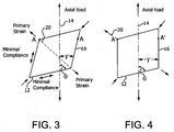
- Figure 3 is a diagram illustrating in two dimensions a parallelogram element defining the relative orientations of the components of the present invention in a first, unstrained configuration.
- the axis of the tubular structure is defined by line 14.
- a first component 12 wrap angle is defined by angle 0 from axis 14.
- a second component 16 wrap angle is defined by angle ⁇ from axis 14.
- the circumference (diameter) of this tube is defined by the distance between points A-A.
- tubes can be designed that can provide increases in diameter during elongation of 5, 10, 15, 20, 25% or more. Even greater diameter changes may be possible, with increases of 30, 35, 40, 45, 50% or more being readily achievable. Theoretically, even more substantial diameter changes of 100% to 500% to 1000% or more may be achieved, restricted by practical material and application limitations, such as true strain off of the oriented axis, wall thinning, axial lengthening, lack of oriented strength, etc. as the angles converge and approach the axis.
- the tube comprises two or more unidirectional bias wraps of material at different angles around the intended axis.
- the angle 0 of the first component is between about 0 and 90 degrees from the tube axis, with about 45 to 85 degrees being more preferred, and about 60 to 80 degrees being most preferable.
- angle ⁇ of the second component is between about 0 and 90 degrees from the tube axis, with about 10 to 80 degrees being more preferred, and about 20 to 60 degrees being most preferable.
- the small pitch, large wrap angle ⁇ component 12 provides hoop strength to the tube; the large pitch / small wrap angle ⁇ component 16 provides axial strength and limits axial strain.
- additional wraps of three, four, five, or more layers of material may be desirable to include additional wraps of three, four, five, or more layers of material to provide additional strength, more thickness or cushioning, modified permeability, or other application-specific desirable properties.
- the components of the tube of the present invention may take numerous forms. For most applications it is preferred to employ tapes of material that provided oriented strength and minimal compliance in the direction of their respective wrap angles.
- the first component should be fixed to the second component such that a change in angle of the first component produces a resulting change in angle of the second component relative to the longitudinal axis of the tube.
- a more compliant material Off of their wrap angles, for many applications it is preferable to have a more compliant material that will allow the orientation of the two active components to change relative to each other so as to provide maximum diameter growth during axial elongation.
- Suitable materials for use in the present invention may include, without limitation, fluoropolymers (especially polytetrafluoroethylene (PTFE) and fluorinated ethylene propylene (FEP)), polyethylenes, polyethylene teraphthalate (PET), nylon, polyurethane, polypropylene, polyester, polyimide, etc., as well as composite materials combining these and/or other materials to achieve the desired strength and compliance characteristics.
- fluoropolymers especially polytetrafluoroethylene (PTFE) and fluorinated ethylene propylene (FEP)
- PET polyethylene teraphthalate
- nylon polyurethane
- polypropylene polypropylene
- polyester polyimide
- polyimide polyimide
- tubes of the present invention may be constructed from a continuous material, such as continuous films, tapes, or sheets of materials.
- the inventive tubes may include discontinuous structures, such as sheets or tapes that include holes or slits therein, or even materials formed from weaves, knits, or other open structures.
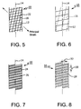
- Figures 5 through 8 illustrate various embodiments that may be useful to practice the present invention.
- Figure 5 illustrates an embodiment of the present invention that comprises a fully open mesh tube 10.
- first component 12 and second component 16 each comprises a fiber or wire material.
- Open spaces 22 are provided between the two components 12, 16 that can be left unfilled or can be covered with a layer of other material (for example, a continuous or discontinuous film).
- Suitable materials that may be used as one or the other or both of components 12, 16 may include metals such as steel, nitinol, etc., polymers such as nylon, ePTFE, etc.
- this construction is believed to provide optimal growth characteristics in accordance with the present invention.
- Figure 6 illustrates an embodiment of a tube 10 of the present invention that comprises a biased wrapped tube of two film (or "tape") components 12, 16.
- the two tape components are uniaxially oriented materials with minimal shear and transverse strength.
- ePTFE is particularly desirable for use as one or both of these components.
- Figure 7 illustrates yet another embodiment of a tube 10 of the present invention.
- This embodiment employs a fine pitch angle helix of full density, high modulus film 24, such as a polyimide, and a low angle pitch of uniaxial film 26, such as ePTFE.
- Figure 8 illustrates still another embodiment of the present invention.
- the tube 10 comprises a homogenous material with both high and low angle orientations defined by oriented slits 28 in the homogenous material.
- Low angle component slits are oriented in helical rows 30 around the circumference of the tube, while high angle component slits are defined as diagonals lines 32 across the low angle rows 30.
- the tube of the present invention can be used both to avoid problems in "necking" found in many prior tube devices, and to provide additional benefits that increases in diameter of the tube during axial elongation can provide.
- the tube of the present invention may be useful as a manufacturing aid, as a deployment sheath (for example, to deliver medical devices), and in other applications that may benefit from easier tubular sheath removal.
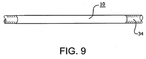
- Figure 9 illustrates one such application wherein the tube 10 is mounted on a manufacturing mandrel 34, such as those commonly employed to construct various tubular structures (e.g:, taped-wrapped vascular graft components). Heating or other processing steps can shrink the tube around the mandrel, making it difficult or impossible to slide the tube off the mandrel once the manufactured article is removed. With the tube of the present invention, axial movement of the tube 10 causes it to diametrically grow, making its removal from the mandrel much easier. This property may also be highly beneficial in assisting in removing a manufactured article from a mandrel.
- a manufacturing mandrel 34 such as those commonly employed to construct various tubular structures (e.g:, taped-wrapped vascular graft components). Heating or other processing steps can shrink the tube around the mandrel, making it difficult or impossible to slide the tube off the mandrel once the manufactured article is removed.
- axial movement of the tube 10 causes it to diametrically grow, making its removal from the
- FIG. 10 Shown in Figure 10 is one embodiment of a tube 10 of the present invention mounted as a containment sheath near the end of a medical device deployment system 36.
- the deployment system comprises a catheter shaft 38 extending from a distal olive 40 to a control hub 42.
- a medical device such as a stent, stent-graft, balloon, blood filter, occluder, probe, valves, etc., may be contained in the sheath 10 to be deployed at a treatment site within a patient's body.
- the sheath 10 may be everted over itself to form two layers, an exterior segment that partially or completely covers an interior segment.
- the tube 10 is attached to a deployment line 44 that is fed into the catheter shaft through opening 46.
- the deployment line 46 is operatively connected to a deployment knob 48 on the hub 42.
- the tube 10 made in accordance with the present invention may be formed from any material that is sufficiently strong both to constrain the device to be delivered and to withstand the tension of the removal process. It is desirable that the sheath 10 also be as thin and lubricious as possible so as to maintain a small device delivery profile and to facilitate the removal process. Since the tube 10 is placed temporarily deep within a patient during delivery and deployment, it is likewise desirable that the sheath be formed from a biocompatible material. As is explained in greater detail below, suitable sheath materials may include:
- the tube 10 In order to actuate the deployment line 44, medical personnel will unscrew the deployment knob 48 and pull on the knob and connected deployment line to cause the tube 10 to progressively withdraw off of the contained device. If the tube 10 is everted over itself, as the exterior segment of the tube is withdrawn, the tube of the present invention will progressively increase in diameter, steadily everting the interior segment so that it becomes the exterior segment of the tube. The diametrical growth of the tube 10 of the present invention aids in the process of everting, since the exterior segment of the tube 10 will form a larger diameter than the unstrained interior segment. As a result, the larger diameter exterior segment slides easily over the interior segment and is readily removed with minimal friction between the two layers.
- FIG. 11 The process of device delivery can be better seen in Figure 11 .
- an exterior segment 50 is shown withdrawing over an interior segment 52, shown exposed in cut-away.
- the axial force opens up the tube 10 of the present invention.
- a constrained self-expanding stent 54 is progressively deployed from this embodiment.
- the exterior segment in the final construct should have an inner diameter that is sufficiently greater than the outer diameter of the interior segment in order to minimize friction between the two segments. That is, in order to minimize interference between the interior segment and the exterior segment, the axially elongated exterior segment should enlarge enough so that its inner diameter comfortably clears the outer diameter of the unstrained interior segment. It is preferred that the inner diameter of the exterior segment be 0.1 to 50 % larger than the outer diameter of the interior segment, and more preferably 10 to 20 % larger.
- a tube with a wall thickness of about 0.08 mm and an exterior segment inner diameter of about 2.1 mm will typically be provided with a unstrained interior segment having an outer diameter of about 1.9 mm.
- the tube of the present invention is believed to vastly reduce the amount of tension required to deploy a device.
- the advantages of the tube of the present invention are believed to be readily adaptable to improve many other devices and processes.
- One example of such improved combination is to employ the tube of the present invention with the pleated tube deployment constructs that are disclosed in co-pending United States Patent Application S.N. 12/014,538 to Irwin et al. filed January 15, 2008 .
- the tube of the present invention can be used with one or more pleats to aid in device delivery and provide further beneficial results.
- the invention of the present invention is believed to have many other useful applications, including angioplasty devices, retrieval devices, implantable filters, stents, compliant grafts, etc. It should be noted that the present invention may be scaled to virtually any dimensions.
- Example 1 Uniaxially oriented ePTFE film
- This Example describes the assembly of an ePTFE tube that can be easily removed from an assembly mandrel.
- a 1" wide expanded polytetrafluroethylene (ePTFE) film (having longitudinally oriented strength, minimal transverse and shear strength, and with FEP on one side functioning as an adhesive) was wrapped at 40° pitch relative to the mandrel axis in a right handed helix orientation with the FEP facing away from the mandrel.
- a 6,35mm (0.25”) wide ePTFE film was wrapped at a 74° pitch in a right handed helix orientation over of the first film with the FEP facing toward the mandrel.
- the assembly was then thermally processed on-mandrel at a temperature of 320°C for 13 minutes. The tube was easily removed from the mandrel and no necking was observed at loads below material yield strength.
- This Example describes the assembly of an ePTFE tube comprising a non-compliant polyimide film (Kapton®) between the ePTFE layers.
- a non-compliant polyimide film Kapton®
- a 1.0" wide ePTFE film was wrapped at a 56° pitch relative to the mandrel axis in a right handed helix orientation with the FEP facing away from the mandrel.
- a 1,27mm x 0,0254mm (0.050" x 0.001”) polyimide film was wrapped at 82° pitch relative to the mandrel axis at a right handed helix orientation over of the first film.
- a 1" wide ePTFE film was wrapped at a 56° pitch relative to the mandrel axis at a right handed helix orientation on top of the polyimide film with the FEP facing toward the mandrel.
- the assembly was then thermally processed on-mandrel at a temperature of 320°C for 13 minutes, after which tube was removed from the mandrel.
- the non-compliant polyimide film used for high angle wrap limits axial strain and allows the use of a higher angle ePTFE wrap.
- the higher angle ePTFE wrap increases the "unwinding" effect for a given axial load.
- the diameter defined by polyimide wrap grows with axial tension but necking can be observed on the ePTFE between the polyimide.
- Example 2 can be modified to reduce necking
- slits were created with a knife into the ePTFE in an orientation parallel that of the film structure (56° pitch relative to the mandrel axis), with approximately 0.050" spacing between the slits. These slits eliminate "off-axis" strength of ePTFE film allowing diametric growth of the polyimide helix under tension without ePTFE necking. Thus, the introduction of these slits eliminates necking.
- This Example describes the assembly of the ePTFE tube as described in Example 1 but on a scaled down version.
- a 1,905mm (0.075”) steel mandrel, 6,35mm (0.25”) wide ePTFE film was wrapped at a 25° pitch relative to the mandrel axis in a right handed helix orientation with the FEP facing away from the mandrel.
- 3,175mm (0.125) wide type ePTFE film wrapped at a 75° pitch relative to the mandrel axis in a right handed helix orientation with the FEP facing toward the mandrel.
- the assembly was then thermally processed on-mandrel at a temperature of 320°C for 13 minutes. This construct was removed from the mandrel and was used as a device constraint which was everted for deployment.
- This Example describes the assembly of a tube which is nearly continuous polyimide which responds well to axial tension and returns to the starting diameter with little relative force.
- a 6,35mm (0.25") wide ePTFE film was wrapped at a 28° pitch angle relative to mandrel axis at a right handed helix orientation with the FEP facing away from the mandrel.
- a 1,0922mm x 0,0254mm (0.043" x .001”) polyimide film was wrapped at 68° pitch angle relative to mandrel axis in a right handed helix orientation over the first film.
- the tube was transferred to a 1,905mm (0.075”) steel mandrel and the polyimide helix was "twisted down” or “coiled” to eliminate clearance between tube and mandrel, effectively increasing pitch angles for all the wraps.
- the tube was then compression wrapped with ePTFE film to immobilize it on the mandrel and thermally processed for 7 minutes at 320°C after which the compression wrap was removed.
- the resultant tube is nearly continuous polyimide and responds well to axial tension, returning to the starting diameter with little relative force.
Landscapes
- Health & Medical Sciences (AREA)
- Engineering & Computer Science (AREA)
- Biomedical Technology (AREA)
- Cardiology (AREA)
- Oral & Maxillofacial Surgery (AREA)
- Transplantation (AREA)
- Heart & Thoracic Surgery (AREA)
- Vascular Medicine (AREA)
- Life Sciences & Earth Sciences (AREA)
- Animal Behavior & Ethology (AREA)
- General Health & Medical Sciences (AREA)
- Public Health (AREA)
- Veterinary Medicine (AREA)
- Materials For Medical Uses (AREA)
- Prostheses (AREA)
- Media Introduction/Drainage Providing Device (AREA)
- Laminated Bodies (AREA)
Applications Claiming Priority (2)
| Application Number | Priority Date | Filing Date | Title |
|---|---|---|---|
| US12/503,785 US8435282B2 (en) | 2009-07-15 | 2009-07-15 | Tube with reverse necking properties |
| PCT/US2010/041765 WO2011008723A1 (en) | 2009-07-15 | 2010-07-13 | Tube with reverse necking properties |
Publications (2)
| Publication Number | Publication Date |
|---|---|
| EP2453848A1 EP2453848A1 (en) | 2012-05-23 |
| EP2453848B1 true EP2453848B1 (en) | 2016-03-23 |
Family
ID=42753482
Family Applications (1)
| Application Number | Title | Priority Date | Filing Date |
|---|---|---|---|
| EP10735114.0A Active EP2453848B1 (en) | 2009-07-15 | 2010-07-13 | Tube with reverse necking properties |
Country Status (10)
Families Citing this family (41)
| Publication number | Priority date | Publication date | Assignee | Title |
|---|---|---|---|---|
| US8845712B2 (en) * | 2008-01-15 | 2014-09-30 | W. L. Gore & Associates, Inc. | Pleated deployment sheath |
| US8936634B2 (en) * | 2009-07-15 | 2015-01-20 | W. L. Gore & Associates, Inc. | Self constraining radially expandable medical devices |
| US8435282B2 (en) * | 2009-07-15 | 2013-05-07 | W. L. Gore & Associates, Inc. | Tube with reverse necking properties |
| US9839540B2 (en) | 2011-01-14 | 2017-12-12 | W. L. Gore & Associates, Inc. | Stent |
| US10166128B2 (en) | 2011-01-14 | 2019-01-01 | W. L. Gore & Associates. Inc. | Lattice |
| US10213329B2 (en) | 2011-08-12 | 2019-02-26 | W. L. Gore & Associates, Inc. | Evertable sheath devices, systems, and methods |
| CA3183330A1 (en) * | 2011-11-10 | 2013-05-16 | Medtronic, Inc. | System for deploying a device to a distal location across a diseased vessel |
| US11213318B2 (en) | 2011-11-10 | 2022-01-04 | Medtronic Vascular, Inc. | Expandable introducer sheath and method |
| US9283072B2 (en) | 2012-07-25 | 2016-03-15 | W. L. Gore & Associates, Inc. | Everting transcatheter valve and methods |
| US10376360B2 (en) | 2012-07-27 | 2019-08-13 | W. L. Gore & Associates, Inc. | Multi-frame prosthetic valve apparatus and methods |
| US9931193B2 (en) | 2012-11-13 | 2018-04-03 | W. L. Gore & Associates, Inc. | Elastic stent graft |
| US9737398B2 (en) | 2012-12-19 | 2017-08-22 | W. L. Gore & Associates, Inc. | Prosthetic valves, frames and leaflets and methods thereof |
| US9968443B2 (en) | 2012-12-19 | 2018-05-15 | W. L. Gore & Associates, Inc. | Vertical coaptation zone in a planar portion of prosthetic heart valve leaflet |
| US9144492B2 (en) | 2012-12-19 | 2015-09-29 | W. L. Gore & Associates, Inc. | Truncated leaflet for prosthetic heart valves, preformed valve |
| US10321986B2 (en) | 2012-12-19 | 2019-06-18 | W. L. Gore & Associates, Inc. | Multi-frame prosthetic heart valve |
| US9101469B2 (en) | 2012-12-19 | 2015-08-11 | W. L. Gore & Associates, Inc. | Prosthetic heart valve with leaflet shelving |
| US10966820B2 (en) | 2012-12-19 | 2021-04-06 | W. L. Gore & Associates, Inc. | Geometric control of bending character in prosthetic heart valve leaflets |
| US9907641B2 (en) | 2014-01-10 | 2018-03-06 | W. L. Gore & Associates, Inc. | Implantable intraluminal device |
| US9763819B1 (en) | 2013-03-05 | 2017-09-19 | W. L. Gore & Associates, Inc. | Tapered sleeve |
| EP3964168A1 (en) | 2013-05-10 | 2022-03-09 | Medtronic, Inc. | System for deploying a device to a distal location across a diseased vessel |
| CA2912204A1 (en) | 2013-05-17 | 2014-11-20 | Transaortic Medical, Inc. | Expandable introducer sheath |
| US10842918B2 (en) | 2013-12-05 | 2020-11-24 | W.L. Gore & Associates, Inc. | Length extensible implantable device and methods for making such devices |
| US10966850B2 (en) | 2014-03-06 | 2021-04-06 | W. L. Gore & Associates, Inc. | Implantable medical device constraint and deployment apparatus |
| US9827094B2 (en) | 2014-09-15 | 2017-11-28 | W. L. Gore & Associates, Inc. | Prosthetic heart valve with retention elements |
| US10603195B1 (en) | 2015-05-20 | 2020-03-31 | Paul Sherburne | Radial expansion and contraction features of medical devices |
| CA3006635A1 (en) * | 2015-05-29 | 2016-12-08 | Duke Empirical, Inc. | Dynamic walled tubing |
| AU2015215913B1 (en) * | 2015-08-20 | 2016-02-25 | Cook Medical Technologies Llc | An endograft delivery device assembly |
| AU2016403450B2 (en) | 2016-04-21 | 2019-10-03 | W. L. Gore & Associates, Inc. | Diametrically adjustable endoprostheses and associated systems and methods |
| US11051939B2 (en) * | 2017-08-31 | 2021-07-06 | Edwards Lifesciences Corporation | Active introducer sheath system |
| EP3681440A1 (en) | 2017-09-12 | 2020-07-22 | W. L. Gore & Associates, Inc. | Leaflet frame attachment for prosthetic valves |
| CN115177403A (zh) | 2017-09-27 | 2022-10-14 | W.L.戈尔及同仁股份有限公司 | 带有可扩张框架的假体瓣膜以及相关系统和方法 |
| EP3687452A1 (en) | 2017-09-27 | 2020-08-05 | W. L. Gore & Associates, Inc. | Prosthetic valves with mechanically coupled leaflets |
| EP3694444A1 (en) | 2017-10-09 | 2020-08-19 | W. L. Gore & Associates, Inc. | Matched stent cover |
| JP7007475B2 (ja) | 2017-10-11 | 2022-01-24 | ダブリュ.エル.ゴア アンド アソシエイツ,インコーポレイティド | インプラント可能メディカルデバイスの拘束及び展開装置 |
| CA3078699C (en) | 2017-10-13 | 2023-10-10 | W.L. Gore & Associates, Inc. | Telescoping prosthetic valve and delivery system |
| EP3703615B1 (en) | 2017-10-31 | 2024-05-15 | W. L. Gore & Associates, Inc. | Transcatheter deployment systems and associated methods |
| CA3205219A1 (en) | 2017-10-31 | 2019-05-09 | Edwards Lifesciences Corporation | Medical valve and leaflet promoting tissue ingrowth |
| JP7227240B2 (ja) | 2017-10-31 | 2023-02-21 | ダブリュ.エル.ゴア アンド アソシエイツ,インコーポレイティド | 人工心臓弁 |
| US11497601B2 (en) | 2019-03-01 | 2022-11-15 | W. L. Gore & Associates, Inc. | Telescoping prosthetic valve with retention element |
| EP4041144A2 (en) * | 2019-10-08 | 2022-08-17 | Edwards Lifesciences Corporation | Expandable sheath |
| EP4601728A2 (en) | 2022-10-20 | 2025-08-20 | QMax, LLC | Tubes and methods of expanding and/or contracting tubes |
Family Cites Families (117)
| Publication number | Priority date | Publication date | Assignee | Title |
|---|---|---|---|---|
| US1453608A (en) | 1922-01-30 | 1923-05-01 | United Shoe Machinery Corp | Shoe stretcher |
| US3225129A (en) | 1962-06-26 | 1965-12-21 | Budd Co | Method of making memory re-shaped plastic tubes, especially fluorocarbon cylinder jackets |
| US4141364A (en) | 1977-03-18 | 1979-02-27 | Jorge Schultze | Expandable endotracheal or urethral tube |
| US4411655A (en) | 1981-11-30 | 1983-10-25 | Schreck David M | Apparatus and method for percutaneous catheterization |
| SE445884B (sv) | 1982-04-30 | 1986-07-28 | Medinvent Sa | Anordning for implantation av en rorformig protes |
| US4569347A (en) | 1984-05-30 | 1986-02-11 | Advanced Cardiovascular Systems, Inc. | Catheter introducing device, assembly and method |
| ES8705239A1 (es) | 1984-12-05 | 1987-05-01 | Medinvent Sa | Un dispositivo para implantar,mediante insercion en un lugarde dificil acceso, una protesis sustancialmente tubular y radialmente expandible |
| US4601713A (en) | 1985-06-11 | 1986-07-22 | Genus Catheter Technologies, Inc. | Variable diameter catheter |
| US4738666A (en) | 1985-06-11 | 1988-04-19 | Genus Catheter Technologies, Inc. | Variable diameter catheter |
| WO1988000813A1 (en) * | 1986-08-05 | 1988-02-11 | St. Jude Medical, Inc. | Braided polyester vascular prosthesis and method |
| SE454482B (sv) | 1986-09-30 | 1988-05-09 | Medinvent Sa | Anordning for implantation |
| SE455834B (sv) | 1986-10-31 | 1988-08-15 | Medinvent Sa | Anordning for transluminal implantation av en i huvudsak rorformig, radiellt expanderbar protes |
| US4921479A (en) | 1987-10-02 | 1990-05-01 | Joseph Grayzel | Catheter sheath with longitudinal seam |
| US5234425A (en) | 1989-03-03 | 1993-08-10 | Thomas J. Fogarty | Variable diameter sheath method and apparatus for use in body passages |
| US5171262A (en) | 1989-06-15 | 1992-12-15 | Cordis Corporation | Non-woven endoprosthesis |
| US5066298A (en) | 1989-11-30 | 1991-11-19 | Progressive Angioplasty Systems, Inc. | Article and method of sheathing angioplasty balloons |
| GB2240926A (en) | 1990-02-14 | 1991-08-21 | Steven Streatfield Gill | An expansible cannula |
| DE4018525C2 (de) | 1990-06-09 | 1994-05-05 | Kaltenbach Martin | Katheter mit einem aufweitbaren Bereich |
| US5201756A (en) | 1990-06-20 | 1993-04-13 | Danforth Biomedical, Inc. | Radially-expandable tubular elements for use in the construction of medical devices |
| US5176659A (en) | 1991-02-28 | 1993-01-05 | Mario Mancini | Expandable intravenous catheter and method of using |
| FR2679484B1 (fr) | 1991-07-26 | 1995-02-17 | Plastic Omnium Cie | Procede pour la realisation de tubes en resine fluoree, notamment en polytetrafluorethylene. |
| US5447503A (en) | 1991-08-14 | 1995-09-05 | Cordis Corporation | Guiding catheter tip having a tapered tip with an expandable lumen |
| US5171305A (en) | 1991-10-17 | 1992-12-15 | Imagyn Medical, Inc. | Linear eversion catheter with reinforced inner body extension |
| US5364345A (en) | 1991-10-18 | 1994-11-15 | Imagyn Medical, Inc. | Method of tubal recanalization and catheter system therefor |
| US6652492B1 (en) | 1991-12-13 | 2003-11-25 | Endovascular Technologies, Inc. | Dual valve, flexible sheath and method |
| US5395349A (en) | 1991-12-13 | 1995-03-07 | Endovascular Technologies, Inc. | Dual valve reinforced sheath and method |
| US5507767A (en) | 1992-01-15 | 1996-04-16 | Cook Incorporated | Spiral stent |
| US5683448A (en) * | 1992-02-21 | 1997-11-04 | Boston Scientific Technology, Inc. | Intraluminal stent and graft |
| US5405377A (en) | 1992-02-21 | 1995-04-11 | Endotech Ltd. | Intraluminal stent |
| US5458573A (en) | 1992-05-01 | 1995-10-17 | American Biomed, Inc. | Everting toposcopic dilation catheter |
| US5352236A (en) | 1992-09-29 | 1994-10-04 | Medtronic, Inc. | Balloon protector |
| DE9321003U1 (de) | 1992-12-30 | 1995-08-10 | Schneider (Usa) Inc., Plymouth, Minn. | Vorrichtung zum Ausbringen von körperimplantierbaren Stents |
| JP3583801B2 (ja) * | 1993-03-03 | 2004-11-04 | ボストン サイエンティフィック リミテッド | 管腔用のステントおよび移植体 |
| US5328469A (en) | 1993-03-19 | 1994-07-12 | Roger Coletti | Hybrid balloon angioplasty catheter and methods of use |
| NL9300500A (nl) | 1993-03-22 | 1994-10-17 | Industrial Res Bv | Uitzetbare, holle huls voor het plaatselijk ondersteunen en/of versterken van een lichaamsvat, alsmede werkwijze voor het vervaardigen daarvan. |
| US6025044A (en) | 1993-08-18 | 2000-02-15 | W. L. Gore & Associates, Inc. | Thin-wall polytetrafluoroethylene tube |
| US5445646A (en) | 1993-10-22 | 1995-08-29 | Scimed Lifesystems, Inc. | Single layer hydraulic sheath stent delivery apparatus and method |
| US5571135A (en) | 1993-10-22 | 1996-11-05 | Scimed Life Systems Inc. | Stent delivery apparatus and method |
| US5789047A (en) | 1993-12-21 | 1998-08-04 | Japan Gore-Tex, Inc | Flexible, multilayered tube |
| EP0682922B1 (de) | 1994-04-26 | 1997-04-09 | Willy Rüsch Ag | Selbstexpandierender Stent für Hohlorgane |
| US5476508A (en) | 1994-05-26 | 1995-12-19 | Tfx Medical | Stent with mutually interlocking filaments |
| US5569183A (en) | 1994-06-01 | 1996-10-29 | Archimedes Surgical, Inc. | Method for performing surgery around a viewing space in the interior of the body |
| US5824041A (en) | 1994-06-08 | 1998-10-20 | Medtronic, Inc. | Apparatus and methods for placement and repositioning of intraluminal prostheses |
| JP3199383B2 (ja) | 1995-04-14 | 2001-08-20 | シュナイダー(ユーエスエー)インク | ローリング膜式ステント供給装置 |
| US5641373A (en) | 1995-04-17 | 1997-06-24 | Baxter International Inc. | Method of manufacturing a radially-enlargeable PTFE tape-reinforced vascular graft |
| EP0840577B1 (en) | 1995-07-07 | 2005-08-24 | W.L. GORE & ASSOCIATES, INC. | Interior liner for tubes, pipes and blood conduits |
| US6042605A (en) | 1995-12-14 | 2000-03-28 | Gore Enterprose Holdings, Inc. | Kink resistant stent-graft |
| US5997508A (en) | 1996-03-28 | 1999-12-07 | Medtronic, Inc. | Expandable percutaneous introducer sheath |
| US5833699A (en) | 1996-04-10 | 1998-11-10 | Chuter; Timothy A. M. | Extending ribbon stent |
| CA2211249C (en) | 1996-07-24 | 2007-07-17 | Cordis Corporation | Balloon catheter and methods of use |
| US5868707A (en) | 1996-08-15 | 1999-02-09 | Advanced Cardiovascular Systems, Inc. | Protective sheath for catheter balloons |
| US6254628B1 (en) | 1996-12-09 | 2001-07-03 | Micro Therapeutics, Inc. | Intracranial stent |
| JP2001504017A (ja) | 1996-11-15 | 2001-03-27 | クック インコーポレーティッド. | 分離可能なスリーブ,ステント配備装置 |
| US5993427A (en) | 1996-12-03 | 1999-11-30 | Laborie Medical Technologies Corp. | Everting tube structure |
| US6352561B1 (en) | 1996-12-23 | 2002-03-05 | W. L. Gore & Associates | Implant deployment apparatus |
| DE19703482A1 (de) * | 1997-01-31 | 1998-08-06 | Ernst Peter Prof Dr M Strecker | Stent |
| US5893868A (en) | 1997-03-05 | 1999-04-13 | Scimed Life Systems, Inc. | Catheter with removable balloon protector and stent delivery system with removable stent protector |
| US5984957A (en) * | 1997-08-12 | 1999-11-16 | Schneider (Usa) Inc | Radially expanded prostheses with axial diameter control |
| US6110146A (en) | 1998-09-30 | 2000-08-29 | Medtronic Ave, Inc. | Protector for catheter balloon with guidewire backloading system |
| US6544278B1 (en) | 1998-11-06 | 2003-04-08 | Scimed Life Systems, Inc. | Rolling membrane stent delivery system |
| US6059813A (en) | 1998-11-06 | 2000-05-09 | Scimed Life Systems, Inc. | Rolling membrane stent delivery system |
| EP1135071A1 (en) | 1998-12-01 | 2001-09-26 | Atropos Limited | A medical device comprising an evertable sleeve |
| US6503270B1 (en) * | 1998-12-03 | 2003-01-07 | Medinol Ltd. | Serpentine coiled ladder stent |
| US6719805B1 (en) * | 1999-06-09 | 2004-04-13 | C. R. Bard, Inc. | Devices and methods for treating tissue |
| US6280412B1 (en) | 1999-06-17 | 2001-08-28 | Scimed Life Systems, Inc. | Stent securement by balloon modification |
| JP3804351B2 (ja) | 1999-08-25 | 2006-08-02 | ニプロ株式会社 | バルーンカテーテル |
| US6371980B1 (en) | 1999-08-30 | 2002-04-16 | Cardiovasc, Inc. | Composite expandable device with impervious polymeric covering and bioactive coating thereon, delivery apparatus and method |
| US6736838B1 (en) * | 2000-03-22 | 2004-05-18 | Zuli Holdings Ltd. | Method and apparatus for covering a stent |
| AUPQ641400A0 (en) | 2000-03-23 | 2000-04-15 | Kleiner, Daniel E. | A device incorporating a hollow member for being positioned along a body cavity of a patient and method of positioning same |
| US6432130B1 (en) | 2000-04-20 | 2002-08-13 | Scimed Life Systems, Inc. | Fully sheathed balloon expandable stent delivery system |
| US6387118B1 (en) | 2000-04-20 | 2002-05-14 | Scimed Life Systems, Inc. | Non-crimped stent delivery system |
| US6607552B1 (en) | 2000-09-18 | 2003-08-19 | Scimed Life Systems, Inc. | Rolling socks |
| US7780603B2 (en) * | 2000-09-25 | 2010-08-24 | Welch Allyn, Inc. | Blood pressure measuring apparatus |
| US6899727B2 (en) | 2001-01-22 | 2005-05-31 | Gore Enterprise Holdings, Inc. | Deployment system for intraluminal devices |
| US6783542B2 (en) | 2001-02-22 | 2004-08-31 | Scimed Life Systems, Inc | Crimpable balloon/stent protector |
| US6547813B2 (en) | 2001-03-23 | 2003-04-15 | Medtronic Ave, Inc. | Stent delivery catheter with folded sleeve and method of making same |
| JP4043210B2 (ja) | 2001-10-09 | 2008-02-06 | オリンパス株式会社 | ステント |
| WO2003045284A2 (en) * | 2001-11-28 | 2003-06-05 | The Research Foundation Of State University Of New York | Endovascular graft and graft trimmer |
| US20050228479A1 (en) | 2001-11-29 | 2005-10-13 | Cook Incorporated | Medical device delivery system |
| US6866679B2 (en) | 2002-03-12 | 2005-03-15 | Ev3 Inc. | Everting stent and stent delivery system |
| US6939327B2 (en) | 2002-05-07 | 2005-09-06 | Cardiac Pacemakers, Inc. | Peel-away sheath |
| DE60315460T2 (de) | 2002-06-28 | 2008-04-30 | Cook Critical Care, Bloomington | Einführungshülse |
| US7115138B2 (en) | 2002-09-04 | 2006-10-03 | Boston Scientific Scimed, Inc. | Sheath tip |
| EP1624909A2 (en) | 2002-09-20 | 2006-02-15 | FlowMedica, Inc. | Appartus and method for inserting an intra-aorta catheter trough a delivery sheath |
| US7105013B2 (en) | 2002-09-30 | 2006-09-12 | Advanced Cardiovascular Systems, Inc. | Protective sleeve assembly for a balloon catheter |
| EP1556117A1 (en) | 2002-10-25 | 2005-07-27 | NMT Medical, Inc. | Expandable sheath tubing |
| US7753945B2 (en) | 2003-01-17 | 2010-07-13 | Gore Enterprise Holdings, Inc. | Deployment system for an endoluminal device |
| US7625337B2 (en) | 2003-01-17 | 2009-12-01 | Gore Enterprise Holdings, Inc. | Catheter assembly |
| US7198636B2 (en) | 2003-01-17 | 2007-04-03 | Gore Enterprise Holdings, Inc. | Deployment system for an endoluminal device |
| GB0310715D0 (en) | 2003-05-09 | 2003-06-11 | Angiomed Ag | Strain management in stent delivery system |
| US8292943B2 (en) | 2003-09-03 | 2012-10-23 | Bolton Medical, Inc. | Stent graft with longitudinal support member |
| US7780692B2 (en) | 2003-12-05 | 2010-08-24 | Onset Medical Corporation | Expandable percutaneous sheath |
| US7699864B2 (en) | 2004-03-18 | 2010-04-20 | Onset Medical Corporation | Expandable medical access device |
| US20050246008A1 (en) * | 2004-04-30 | 2005-11-03 | Novostent Corporation | Delivery system for vascular prostheses and methods of use |
| CA2565106C (en) | 2004-05-25 | 2013-11-05 | Chestnut Medical Technologies, Inc. | Flexible vascular occluding device |
| EP1621160B1 (en) | 2004-07-28 | 2008-03-26 | Cordis Corporation | Low deployment force delivery device |
| US7955370B2 (en) | 2004-08-06 | 2011-06-07 | Boston Scientific Scimed, Inc. | Stent delivery system |
| US7393358B2 (en) | 2004-08-17 | 2008-07-01 | Boston Scientific Scimed, Inc. | Stent delivery system |
| US7691137B2 (en) | 2004-09-28 | 2010-04-06 | Boston Scientific Scimed, Inc. | Rotatable sheath, assembly and method of manufacture of same |
| WO2006049121A1 (ja) * | 2004-11-05 | 2006-05-11 | Ulvac, Inc. | プラズマディスプレイパネル用保護膜及びその保護膜の製造方法、プラズマディスプレイパネル及びその製造方法 |
| US7578838B2 (en) | 2005-01-12 | 2009-08-25 | Cook Incorporated | Delivery system with helical shaft |
| US20060184225A1 (en) | 2005-02-11 | 2006-08-17 | Medtronic Vascular, Inc. | Force distributing system for delivering a self-expanding stent |
| US7918880B2 (en) | 2005-02-16 | 2011-04-05 | Boston Scientific Scimed, Inc. | Self-expanding stent and delivery system |
| US7632296B2 (en) | 2005-03-03 | 2009-12-15 | Boston Scientific Scimed, Inc. | Rolling membrane with hydraulic recapture means for self expanding stent |
| US8435279B2 (en) | 2005-06-14 | 2013-05-07 | Advanced Cardiovascular Systems, Inc. | Delivery system for a device such as a stent |
| DE102005056529A1 (de) * | 2005-11-28 | 2007-05-31 | Mnemoscience Gmbh | Komprimierbare tubuläre Gewebestützen |
| US20070123994A1 (en) * | 2005-11-29 | 2007-05-31 | Ethicon Endo-Surgery, Inc. | Internally Placed Gastric Restriction Device |
| EP1959876B1 (en) * | 2005-12-02 | 2011-09-28 | PNN Medical A/S | A stent |
| US9375215B2 (en) | 2006-01-20 | 2016-06-28 | W. L. Gore & Associates, Inc. | Device for rapid repair of body conduits |
| US7785290B2 (en) | 2006-08-07 | 2010-08-31 | Gore Enterprise Holdings, Inc. | Non-shortening high angle wrapped balloons |
| US7780630B2 (en) | 2007-03-30 | 2010-08-24 | Boston Scientific Scimed, Inc. | Perfusion device |
| US20080255678A1 (en) * | 2007-04-13 | 2008-10-16 | Cully Edward H | Medical apparatus and method of making the same |
| US8372138B2 (en) | 2007-06-12 | 2013-02-12 | Boston Scientific Scimed, Inc. | Shape memory polymeric stent |
| CA2691064C (en) | 2007-06-22 | 2015-11-24 | David L. Bogert | Helical and segmented stent-graft |
| DE102008048416A1 (de) * | 2008-08-05 | 2010-02-11 | Acandis Gmbh & Co. Kg | Medizinische Vorrichtung und Verfahren zum Herstellen einer derartigen Vorrichtung |
| DE102008048417A1 (de) | 2008-09-23 | 2010-04-01 | Acandis Gmbh & Co. Kg | Medizinische Vorrichtung |
| US8435282B2 (en) * | 2009-07-15 | 2013-05-07 | W. L. Gore & Associates, Inc. | Tube with reverse necking properties |
-
2009
- 2009-07-15 US US12/503,785 patent/US8435282B2/en active Active
-
2010
- 2010-07-13 WO PCT/US2010/041765 patent/WO2011008723A1/en active Application Filing
- 2010-07-13 CA CA2857850A patent/CA2857850A1/en not_active Abandoned
- 2010-07-13 ES ES10735114.0T patent/ES2575244T3/es active Active
- 2010-07-13 AU AU2010273611A patent/AU2010273611B2/en active Active
- 2010-07-13 CA CA2767540A patent/CA2767540C/en active Active
- 2010-07-13 BR BR112012000678-9A patent/BR112012000678A2/pt not_active Application Discontinuation
- 2010-07-13 CN CN201080032628.XA patent/CN102573709B/zh active Active
- 2010-07-13 RU RU2012105282/14A patent/RU2542086C2/ru active
- 2010-07-13 JP JP2012520709A patent/JP5857173B2/ja active Active
- 2010-07-13 EP EP10735114.0A patent/EP2453848B1/en active Active
-
2013
- 2013-02-06 US US13/761,003 patent/US9114037B2/en active Active
- 2013-04-18 US US13/865,788 patent/US8801774B2/en active Active
-
2014
- 2014-08-14 RU RU2014133539A patent/RU2014133539A/ru not_active Application Discontinuation
Also Published As
| Publication number | Publication date |
|---|---|
| US20130238080A1 (en) | 2013-09-12 |
| HK1164680A1 (zh) | 2012-09-28 |
| CA2767540A1 (en) | 2011-01-20 |
| RU2542086C2 (ru) | 2015-02-20 |
| CN102573709B (zh) | 2014-08-20 |
| CA2857850A1 (en) | 2011-01-20 |
| US20110015716A1 (en) | 2011-01-20 |
| RU2014133539A (ru) | 2016-03-10 |
| JP2012533347A (ja) | 2012-12-27 |
| RU2012105282A (ru) | 2013-08-20 |
| JP5857173B2 (ja) | 2016-02-10 |
| CN102573709A (zh) | 2012-07-11 |
| US20130150949A1 (en) | 2013-06-13 |
| BR112012000678A2 (pt) | 2020-09-24 |
| AU2010273611B2 (en) | 2014-04-17 |
| US9114037B2 (en) | 2015-08-25 |
| EP2453848A1 (en) | 2012-05-23 |
| ES2575244T3 (es) | 2016-06-27 |
| CA2767540C (en) | 2014-10-07 |
| AU2010273611A1 (en) | 2012-02-02 |
| WO2011008723A1 (en) | 2011-01-20 |
| US8801774B2 (en) | 2014-08-12 |
| US8435282B2 (en) | 2013-05-07 |
Similar Documents
| Publication | Publication Date | Title |
|---|---|---|
| EP2453848B1 (en) | Tube with reverse necking properties | |
| US20220125610A1 (en) | Evertable sheath devices, systems, and methods | |
| EP2249749B1 (en) | Pleated deployment sheath | |
| US8936634B2 (en) | Self constraining radially expandable medical devices | |
| HK1164680B (en) | Tube with reverse necking properties | |
| HK1150530B (en) | Pleated deployment sheath | |
| AU2012216515A1 (en) | Pleated deployment sheath | |
| HK1198808B (en) | Evertable sheath devices and systems |
Legal Events
| Date | Code | Title | Description |
|---|---|---|---|
| PUAI | Public reference made under article 153(3) epc to a published international application that has entered the european phase |
Free format text: ORIGINAL CODE: 0009012 |
|
| 17P | Request for examination filed |
Effective date: 20120213 |
|
| AK | Designated contracting states |
Kind code of ref document: A1 Designated state(s): AL AT BE BG CH CY CZ DE DK EE ES FI FR GB GR HR HU IE IS IT LI LT LU LV MC MK MT NL NO PL PT RO SE SI SK SM TR |
|
| REG | Reference to a national code |
Ref country code: HK Ref legal event code: DE Ref document number: 1164680 Country of ref document: HK |
|
| DAX | Request for extension of the european patent (deleted) | ||
| 17Q | First examination report despatched |
Effective date: 20140425 |
|
| REG | Reference to a national code |
Ref country code: DE Ref legal event code: R079 Ref document number: 602010031423 Country of ref document: DE Free format text: PREVIOUS MAIN CLASS: A61F0002840000 Ipc: A61F0002820000 |
|
| RIC1 | Information provided on ipc code assigned before grant |
Ipc: A61F 2/962 20130101ALI20150724BHEP Ipc: A61F 2/966 20130101ALI20150724BHEP Ipc: A61F 2/82 20130101AFI20150724BHEP Ipc: A61F 2/88 20060101ALI20150724BHEP |
|
| GRAP | Despatch of communication of intention to grant a patent |
Free format text: ORIGINAL CODE: EPIDOSNIGR1 |
|
| RAP1 | Party data changed (applicant data changed or rights of an application transferred) |
Owner name: W.L. GORE & ASSOCIATES, INC. |
|
| INTG | Intention to grant announced |
Effective date: 20151001 |
|
| GRAS | Grant fee paid |
Free format text: ORIGINAL CODE: EPIDOSNIGR3 |
|
| GRAA | (expected) grant |
Free format text: ORIGINAL CODE: 0009210 |
|
| RIN1 | Information on inventor provided before grant (corrected) |
Inventor name: SILVERMAN, JAMES, D. |
|
| AK | Designated contracting states |
Kind code of ref document: B1 Designated state(s): AL AT BE BG CH CY CZ DE DK EE ES FI FR GB GR HR HU IE IS IT LI LT LU LV MC MK MT NL NO PL PT RO SE SI SK SM TR |
|
| REG | Reference to a national code |
Ref country code: GB Ref legal event code: FG4D |
|
| REG | Reference to a national code |
Ref country code: CH Ref legal event code: EP |
|
| REG | Reference to a national code |
Ref country code: AT Ref legal event code: REF Ref document number: 782368 Country of ref document: AT Kind code of ref document: T Effective date: 20160415 |
|
| REG | Reference to a national code |
Ref country code: IE Ref legal event code: FG4D |
|
| REG | Reference to a national code |
Ref country code: DE Ref legal event code: R096 Ref document number: 602010031423 Country of ref document: DE |
|
| REG | Reference to a national code |
Ref country code: FR Ref legal event code: PLFP Year of fee payment: 7 |
|
| REG | Reference to a national code |
Ref country code: ES Ref legal event code: FG2A Ref document number: 2575244 Country of ref document: ES Kind code of ref document: T3 Effective date: 20160627 |
|
| REG | Reference to a national code |
Ref country code: LT Ref legal event code: MG4D |
|
| REG | Reference to a national code |
Ref country code: NL Ref legal event code: MP Effective date: 20160323 |
|
| PG25 | Lapsed in a contracting state [announced via postgrant information from national office to epo] |
Ref country code: GR Free format text: LAPSE BECAUSE OF FAILURE TO SUBMIT A TRANSLATION OF THE DESCRIPTION OR TO PAY THE FEE WITHIN THE PRESCRIBED TIME-LIMIT Effective date: 20160624 Ref country code: FI Free format text: LAPSE BECAUSE OF FAILURE TO SUBMIT A TRANSLATION OF THE DESCRIPTION OR TO PAY THE FEE WITHIN THE PRESCRIBED TIME-LIMIT Effective date: 20160323 Ref country code: NO Free format text: LAPSE BECAUSE OF FAILURE TO SUBMIT A TRANSLATION OF THE DESCRIPTION OR TO PAY THE FEE WITHIN THE PRESCRIBED TIME-LIMIT Effective date: 20160623 Ref country code: HR Free format text: LAPSE BECAUSE OF FAILURE TO SUBMIT A TRANSLATION OF THE DESCRIPTION OR TO PAY THE FEE WITHIN THE PRESCRIBED TIME-LIMIT Effective date: 20160323 |
|
| REG | Reference to a national code |
Ref country code: AT Ref legal event code: MK05 Ref document number: 782368 Country of ref document: AT Kind code of ref document: T Effective date: 20160323 |
|
| PG25 | Lapsed in a contracting state [announced via postgrant information from national office to epo] |
Ref country code: LT Free format text: LAPSE BECAUSE OF FAILURE TO SUBMIT A TRANSLATION OF THE DESCRIPTION OR TO PAY THE FEE WITHIN THE PRESCRIBED TIME-LIMIT Effective date: 20160323 Ref country code: LV Free format text: LAPSE BECAUSE OF FAILURE TO SUBMIT A TRANSLATION OF THE DESCRIPTION OR TO PAY THE FEE WITHIN THE PRESCRIBED TIME-LIMIT Effective date: 20160323 Ref country code: NL Free format text: LAPSE BECAUSE OF FAILURE TO SUBMIT A TRANSLATION OF THE DESCRIPTION OR TO PAY THE FEE WITHIN THE PRESCRIBED TIME-LIMIT Effective date: 20160323 Ref country code: SE Free format text: LAPSE BECAUSE OF FAILURE TO SUBMIT A TRANSLATION OF THE DESCRIPTION OR TO PAY THE FEE WITHIN THE PRESCRIBED TIME-LIMIT Effective date: 20160323 |
|
| PG25 | Lapsed in a contracting state [announced via postgrant information from national office to epo] |
Ref country code: EE Free format text: LAPSE BECAUSE OF FAILURE TO SUBMIT A TRANSLATION OF THE DESCRIPTION OR TO PAY THE FEE WITHIN THE PRESCRIBED TIME-LIMIT Effective date: 20160323 Ref country code: PL Free format text: LAPSE BECAUSE OF FAILURE TO SUBMIT A TRANSLATION OF THE DESCRIPTION OR TO PAY THE FEE WITHIN THE PRESCRIBED TIME-LIMIT Effective date: 20160323 Ref country code: IS Free format text: LAPSE BECAUSE OF FAILURE TO SUBMIT A TRANSLATION OF THE DESCRIPTION OR TO PAY THE FEE WITHIN THE PRESCRIBED TIME-LIMIT Effective date: 20160723 |
|
| PG25 | Lapsed in a contracting state [announced via postgrant information from national office to epo] |
Ref country code: AT Free format text: LAPSE BECAUSE OF FAILURE TO SUBMIT A TRANSLATION OF THE DESCRIPTION OR TO PAY THE FEE WITHIN THE PRESCRIBED TIME-LIMIT Effective date: 20160323 Ref country code: CZ Free format text: LAPSE BECAUSE OF FAILURE TO SUBMIT A TRANSLATION OF THE DESCRIPTION OR TO PAY THE FEE WITHIN THE PRESCRIBED TIME-LIMIT Effective date: 20160323 Ref country code: SM Free format text: LAPSE BECAUSE OF FAILURE TO SUBMIT A TRANSLATION OF THE DESCRIPTION OR TO PAY THE FEE WITHIN THE PRESCRIBED TIME-LIMIT Effective date: 20160323 Ref country code: RO Free format text: LAPSE BECAUSE OF FAILURE TO SUBMIT A TRANSLATION OF THE DESCRIPTION OR TO PAY THE FEE WITHIN THE PRESCRIBED TIME-LIMIT Effective date: 20160323 Ref country code: SK Free format text: LAPSE BECAUSE OF FAILURE TO SUBMIT A TRANSLATION OF THE DESCRIPTION OR TO PAY THE FEE WITHIN THE PRESCRIBED TIME-LIMIT Effective date: 20160323 Ref country code: PT Free format text: LAPSE BECAUSE OF FAILURE TO SUBMIT A TRANSLATION OF THE DESCRIPTION OR TO PAY THE FEE WITHIN THE PRESCRIBED TIME-LIMIT Effective date: 20160725 |
|
| PG25 | Lapsed in a contracting state [announced via postgrant information from national office to epo] |
Ref country code: BE Free format text: LAPSE BECAUSE OF FAILURE TO SUBMIT A TRANSLATION OF THE DESCRIPTION OR TO PAY THE FEE WITHIN THE PRESCRIBED TIME-LIMIT Effective date: 20160323 |
|
| REG | Reference to a national code |
Ref country code: DE Ref legal event code: R097 Ref document number: 602010031423 Country of ref document: DE |
|
| PLBE | No opposition filed within time limit |
Free format text: ORIGINAL CODE: 0009261 |
|
| STAA | Information on the status of an ep patent application or granted ep patent |
Free format text: STATUS: NO OPPOSITION FILED WITHIN TIME LIMIT |
|
| PG25 | Lapsed in a contracting state [announced via postgrant information from national office to epo] |
Ref country code: DK Free format text: LAPSE BECAUSE OF FAILURE TO SUBMIT A TRANSLATION OF THE DESCRIPTION OR TO PAY THE FEE WITHIN THE PRESCRIBED TIME-LIMIT Effective date: 20160323 |
|
| PG25 | Lapsed in a contracting state [announced via postgrant information from national office to epo] |
Ref country code: BG Free format text: LAPSE BECAUSE OF FAILURE TO SUBMIT A TRANSLATION OF THE DESCRIPTION OR TO PAY THE FEE WITHIN THE PRESCRIBED TIME-LIMIT Effective date: 20160623 |
|
| REG | Reference to a national code |
Ref country code: CH Ref legal event code: PL |
|
| 26N | No opposition filed |
Effective date: 20170102 |
|
| PG25 | Lapsed in a contracting state [announced via postgrant information from national office to epo] |
Ref country code: MC Free format text: LAPSE BECAUSE OF FAILURE TO SUBMIT A TRANSLATION OF THE DESCRIPTION OR TO PAY THE FEE WITHIN THE PRESCRIBED TIME-LIMIT Effective date: 20160323 |
|
| PG25 | Lapsed in a contracting state [announced via postgrant information from national office to epo] |
Ref country code: LI Free format text: LAPSE BECAUSE OF NON-PAYMENT OF DUE FEES Effective date: 20160731 Ref country code: CH Free format text: LAPSE BECAUSE OF NON-PAYMENT OF DUE FEES Effective date: 20160731 |
|
| PG25 | Lapsed in a contracting state [announced via postgrant information from national office to epo] |
Ref country code: SI Free format text: LAPSE BECAUSE OF FAILURE TO SUBMIT A TRANSLATION OF THE DESCRIPTION OR TO PAY THE FEE WITHIN THE PRESCRIBED TIME-LIMIT Effective date: 20160323 |
|
| REG | Reference to a national code |
Ref country code: FR Ref legal event code: PLFP Year of fee payment: 8 |
|
| PG25 | Lapsed in a contracting state [announced via postgrant information from national office to epo] |
Ref country code: LU Free format text: LAPSE BECAUSE OF NON-PAYMENT OF DUE FEES Effective date: 20160713 |
|
| PG25 | Lapsed in a contracting state [announced via postgrant information from national office to epo] |
Ref country code: CY Free format text: LAPSE BECAUSE OF FAILURE TO SUBMIT A TRANSLATION OF THE DESCRIPTION OR TO PAY THE FEE WITHIN THE PRESCRIBED TIME-LIMIT Effective date: 20160323 Ref country code: HU Free format text: LAPSE BECAUSE OF FAILURE TO SUBMIT A TRANSLATION OF THE DESCRIPTION OR TO PAY THE FEE WITHIN THE PRESCRIBED TIME-LIMIT; INVALID AB INITIO Effective date: 20100713 |
|
| REG | Reference to a national code |
Ref country code: FR Ref legal event code: PLFP Year of fee payment: 9 |
|
| PG25 | Lapsed in a contracting state [announced via postgrant information from national office to epo] |
Ref country code: MT Free format text: LAPSE BECAUSE OF NON-PAYMENT OF DUE FEES Effective date: 20160731 Ref country code: MK Free format text: LAPSE BECAUSE OF FAILURE TO SUBMIT A TRANSLATION OF THE DESCRIPTION OR TO PAY THE FEE WITHIN THE PRESCRIBED TIME-LIMIT Effective date: 20160323 Ref country code: TR Free format text: LAPSE BECAUSE OF FAILURE TO SUBMIT A TRANSLATION OF THE DESCRIPTION OR TO PAY THE FEE WITHIN THE PRESCRIBED TIME-LIMIT Effective date: 20160323 |
|
| PG25 | Lapsed in a contracting state [announced via postgrant information from national office to epo] |
Ref country code: AL Free format text: LAPSE BECAUSE OF FAILURE TO SUBMIT A TRANSLATION OF THE DESCRIPTION OR TO PAY THE FEE WITHIN THE PRESCRIBED TIME-LIMIT Effective date: 20160323 |
|
| P01 | Opt-out of the competence of the unified patent court (upc) registered |
Effective date: 20230516 |
|
| PGFP | Annual fee paid to national office [announced via postgrant information from national office to epo] |
Ref country code: IT Payment date: 20240619 Year of fee payment: 15 |
|
| PGFP | Annual fee paid to national office [announced via postgrant information from national office to epo] |
Ref country code: DE Payment date: 20240619 Year of fee payment: 15 |
|
| PGFP | Annual fee paid to national office [announced via postgrant information from national office to epo] |
Ref country code: ES Payment date: 20240802 Year of fee payment: 15 |
|
| PGFP | Annual fee paid to national office [announced via postgrant information from national office to epo] |
Ref country code: GB Payment date: 20250619 Year of fee payment: 16 |
|
| PGFP | Annual fee paid to national office [announced via postgrant information from national office to epo] |
Ref country code: FR Payment date: 20250620 Year of fee payment: 16 |
|
| PGFP | Annual fee paid to national office [announced via postgrant information from national office to epo] |
Ref country code: IE Payment date: 20250623 Year of fee payment: 16 |