EP2453385A2 - Vorrichtung und Verfahren zur Personenidentifizierung - Google Patents
Vorrichtung und Verfahren zur Personenidentifizierung Download PDFInfo
- Publication number
- EP2453385A2 EP2453385A2 EP11008757A EP11008757A EP2453385A2 EP 2453385 A2 EP2453385 A2 EP 2453385A2 EP 11008757 A EP11008757 A EP 11008757A EP 11008757 A EP11008757 A EP 11008757A EP 2453385 A2 EP2453385 A2 EP 2453385A2
- Authority
- EP
- European Patent Office
- Prior art keywords
- finger
- identification
- blood vessel
- image
- suitability
- Prior art date
- Legal status (The legal status is an assumption and is not a legal conclusion. Google has not performed a legal analysis and makes no representation as to the accuracy of the status listed.)
- Granted
Links
Images









Classifications
-
- G—PHYSICS
- G06—COMPUTING OR CALCULATING; COUNTING
- G06V—IMAGE OR VIDEO RECOGNITION OR UNDERSTANDING
- G06V10/00—Arrangements for image or video recognition or understanding
- G06V10/98—Detection or correction of errors, e.g. by rescanning the pattern or by human intervention; Evaluation of the quality of the acquired patterns
- G06V10/993—Evaluation of the quality of the acquired pattern
-
- G—PHYSICS
- G06—COMPUTING OR CALCULATING; COUNTING
- G06V—IMAGE OR VIDEO RECOGNITION OR UNDERSTANDING
- G06V40/00—Recognition of biometric, human-related or animal-related patterns in image or video data
- G06V40/10—Human or animal bodies, e.g. vehicle occupants or pedestrians; Body parts, e.g. hands
- G06V40/12—Fingerprints or palmprints
- G06V40/1341—Sensing with light passing through the finger
-
- G—PHYSICS
- G06—COMPUTING OR CALCULATING; COUNTING
- G06V—IMAGE OR VIDEO RECOGNITION OR UNDERSTANDING
- G06V40/00—Recognition of biometric, human-related or animal-related patterns in image or video data
- G06V40/10—Human or animal bodies, e.g. vehicle occupants or pedestrians; Body parts, e.g. hands
- G06V40/14—Vascular patterns
Definitions
- the present invention relates to a personal identification device using a living body, and more particularly to an identification technique using a blood vessel pattern obtained by imaging light transmitted through a living body.
- Biometric authentication is an authentication technique using human biometric information, which is excellent in convenience and confidentiality.
- biometric authentication using fingerprints irises, voices, faces, veins of the back of the hand, or finger veins.
- biometric authentication using veins is excellent in tamper resistance because the biometric authentication uses internal information of a living body.
- the finger vein authentication device applies infrared light to a finger.
- the infrared light is scattered in the inside of the finger, and then transmitted to the outside.
- the finger vein authentication device images the infrared light transmitted through the palm surface of the finger.
- hemoglobin in blood absorbs the infrared light more than the tissue therearound does.
- the light transmitted through the palm surface of the finger has a contrast difference between a weak light that is decayed because the light is transmitted through a vein and a strong light that is not decayed because the light is transmitted through a portion with no veins.
- finger veins distributed under the palm skin of the finger are visualized in dark shadow patterns (finger vein patterns) on the image imaged by the finger vein authentication device.
- the finger vein authentication device identifies individuals, in which the features of finger vein patterns of a user are registered in advance and the correlation is determined between the finger vein patterns of the user presented in performing identification and the features registered in advance.
- the vein authentication device in the mode of shooting a transmitted light as described above can shoot sharp vein patterns at high contrast, the vein authentication device has advantages such as a high identification accuracy and a low failure-to-enroll rate (FTER).
- Japanese Patent Application Laid-Open Publication No. 2004-265269 for example.
- This device applies infrared light from the right and left side of a finger to shoot a finger vein image.
- Japanese Patent Application Laid-Open Publication No. 2009-172064 discloses a device and method of improving identification accuracy by removing finger wrinkle information from a shot image.
- vein authentication using fingers or palms is known as authentication with a low failure-to-enroll rate, it is known that there are rare fingers or the like unsuitable for vein authentication.
- the finger unsuitable for identification is a finger whose vein patterns are difficult to be shot sharply.
- An identification device and system includes a light source, an imager configured to image light transmitted through a living body, and a processor configured to perform identification based on a blood vessel pattern imaged at the imager.
- the processor evaluates suitability for identification, from body surface information and blood vessel information in the blood vessel pattern based on a shot image.
- an identification device and system with excellent usability that can evaluate the suitability of a user for personal identification based on body surface information and blood vessel information in consideration of the evaluated result of suitability.
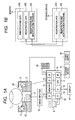
- Fig. 1A is a block diagram illustrating an identification system according to a first embodiment.
- This identification system is a blood vessel image extractor, including a data capture device 2 that captures an image including blood vessel patterns such as veins of a living body, an image inputter 18, an identification processor 10, a storage device 14, a display 17, an information inputter 19, a sound outputter 6, and a power supply 15.
- the data capture device 2 is a single cabinet, having a light source 3, an imager 4, and a finger stage 26.
- the light source 3 is an infrared light emitting diode (LED), for example, which applies infrared light to a finger 1 presented on the finger stage 26.
- the imager 4 images the presented finger 1.
- the image inputter 18 inputs the image imaged at the imager 4 to the identification processor 10 that functions as a processor. It is noted that such a configuration is also possible that the image inputter 18 performs a process of extracting a blood vessel pattern image from the image imaged at the imager 4 and the extracted blood vessel pattern image is inputted to the identification processor 10.
- a blood vessel image extractor is integrally formed of the image inputter 18 and the data capture device 2, and that the image inputter 18 is integrally formed with the identification processor 10.
- the identification processor 10 includes a central processing unit (CPU) 11, a memory 12, and various interfaces (IFs) 13.
- the CPU 11 executes a program 100 stored in the memory 12 to perform various processes.
- the memory 12 stores images inputted from the image inputter 18.
- the memory 12 temporarily stores the program 100 executed by the CPU 11.
- the interfaces 13 are connected to the external devices of the identification processor 10. More specifically, the interfaces 13 are connected to the data capture device 2, the storage device 14, the display 17, the information inputter 19, the sound outputter 6, the image inputter 18, and so on.
- the storage device 14 stores registration data 220 of a user and the program 100.
- Registration data 220 shown in Fig. 1B is information to verify the user, which is the image of blood vessel patterns or the like, for example.
- the image of the blood vessel patterns is an image that blood vessels distributed under the palm skin of the finger are imaged in dark shadow patterns.
- the display 17 is a liquid crystal display or the like, for example, which displays information received from the identification processor 10.
- the information inputter 19 is a keyboard, a touch panel, or the like, for example, which sends information inputted from the user to the identification processor 10.
- the sound outputter 6 is a speaker or the like, which provides information received from the identification processor 10 in sounds.
- the power supply 15 is a dry battery or an external power supply, which supplies power to drive the data capture device 2 and the identification processor 10.
- a finger is used for a living body portion and vein patterns are used for blood vessel patterns.
- the blood vessel patterns of the palm may be used, and other portions of the living body may be used.
- the identification system when the user presents the finger 1 on the data capture device 2, infrared light is applied from the light source 3 to the finger 1. The light is scattered in the inside of the finger 1, and the light transmitted through the finger 1 enters the imager 4. The incident light is converted into electric signals at the imager 4, and captured as an image at the identification processor 10. The captured image is stored in the memory 12.
- the registration data 220 and the program 100 stored in the storage device 14 are stored from the storage device 14 into the memory 12 ( Fig. 1B ).
- the CPU 11 creates identification data 240 from an inputted image according to the program 100 stored in the memory 12 to verify the identification data 240 against the registration data 220.
- the correlation between two items of data in comparison is calculated to determine whether the identification data 240 is matched with the registered data depending on the correlation value. This determined result is used to identify an individual. The identified result is displayed on the display 17, or noticed in sounds from the sound outputter 6.
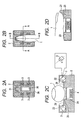
- Figs. 2A to 2D are diagrams illustrating the appearance of the data capture device 2 according to the first embodiment.
- Fig. 2A is a top view illustrating the device 2
- Fig. 2B is a top view illustrating the device 2 on which a finger is presented
- Fig. 2C is a cross sectional view on a line A-A in Fig. 2B
- Fig. 2D is a cross sectional view on a line B-B in Fig. 2B .
- the finger stage 26 is provided to form a presentation region in which the user guides the finger for identification to an imaging region.
- An opening 20 is formed in the finger stage 26.
- a living body portion is contacted with the finger stage 26 to also facilitate positioning, the living body portion is not necessarily contacted with the finger stage 26. It is sufficient that the finger is presented on the inside of the imaging region.
- the opening 20 may be provided with an infrared transmission filter 24 in such a way that the infrared transmission filter 24 covers the opening 20. It is possible to prevent unnecessary light other than infrared light from entering the device by providing the infrared transmission filter 24. In addition, it is possible to prevent foreign substances such as dust or contaminants from entering the device. It is sufficient that the filter 24 is provided at a position a few millimeters lower than the finger stage 26 to prevent the finger 1 from contacting with the filter 24. Thus, it is possible to prevent the blood vessel pattern from disappearing or deforming by pressing a finger. In addition, it is possible to prevent the filter 24 from being contaminated.
- the imager 4 is provided right below the opening 20.
- the light source 3 formed of one or plural light source elements applies infrared light to the finger 1.
- the light is scattered in every direction.
- the light scattered in the inside of the finger partially reaches an area above the opening 20, and the light reaching the area partially travels from the inside of the finger toward the outside of the finger.
- the light passes through the opening 20 and the filter 24, and is shot with the imager 4. Since the light is transmitted from the inside of the finger 1 through the palm surface of the finger 1, the light has a contrast difference between a weak light that is decayed because the light is transmitted through veins and a strong light that is not decayed because the light is transmitted through portions with no veins.
- an image of finger vein patterns in a partial region positioned right above the opening 20 appears. Therefore, the finger vein patterns in the partial region of the finger 1 are acquired.
- the size of the opening 20 is made smaller than the width and length of the finger 1 to completely cover the opening 20 with the finger 1 when the user presents the finger 1.
- the device 2 may be provided with a projection 21 to position the finger 1.
- the projection 21 is provided to allow the user to present the finger with the fingertip aligned at the projection 21 ( Fig. 2D ).
- the projection 21 can prevent the finger 1 from being placed at a position shifted from the specified position.
- the opening 20 is located in the region in which the finger is presented, desirably, the opening 20 is provided at the position at which the first joint of the finger and the portion therearound can be shot when the user places the finger aligned at the projection 21. This is because the skin on the finger joint portion is thinner than the skins on the other portions and veins tend to be shot.
- a touch sensor 23 may be provided on the fingertip side and finger base side of the finger stage 26.
- the touch sensors 23 is provided to allow a detection that the user's finger is presented.
- the device 2 is provided with the infrared source 3 used for shooting veins.
- the infrared source 3 is formed of one or plural light source elements such as LEDs.
- the position of disposing the light source is on the lateral sides in the region in which the finger 1 is presented (in the major axis direction of the finger).
- the light source is disposed at a position lower than the half of the height of the finger.
- an angle ⁇ at which the light source is disposed ranges from 0 ⁇ ⁇ ⁇ 90 degrees, and light is applied diagonally upward.
- the light source is disposed on the right and left side of the finger as tilted diagonally upward, so that light can be applied to a high position of the finger. Thus, it is possible to shoot a sharp vein image.
- the light source is disposed on the inner side of the finger width, light is applied to the palm side of the finger 1, that is, the palm surface of the finger, so that the sharpness of the shot image is reduced.
- the arrangement of the light source is not limited to disposing the light source on the lateral sides.
- the number of the light sources may be one or plurals.
- the light source may be disposed at a position above the presentation region for the living body (at a position opposite the surface on which the device is provided), or may be disposed at a position below the disposed presentation region for the living body.
- the light source may be disposed on the back side of the presentation region for the living body when seen from the user side.
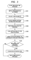
- a finger presentation detection process (S101) is performed in which it is determined whether a finger is presented (placed) on the inside of the imaging region of the device. If the finger is presented, a light quantity adjusting process (S103) is performed for applying an appropriate light quantity from the light source. After completion of adjusting the light quantity, a pattern extraction process (S108) and a feature data creation process (S109) are performed. Subsequently, the identification suitability of the finger targeted for registration is evaluated (S120).
- the CPU 11 is a processor that functions as a feature extractor and a feature verifier as well as a light quantity controller and an evaluator to evaluate the identification suitability of a finger.
- the identification device presents the evaluated result to the user (S122). The user sees the presented evaluated result to select whether to continue the registration process as is or to cancel the registration process. If the user selects to continue the registration process, the identification system stores feature data created in the feature data creation process (S109) in the storage device 14 to complete the registration process. If the user selects to cancel the registration process, the identification system discards feature data to end the registration process.
- the flow may be performed at the identification processor 10, or may be shared with the image inputter in such a way that the processes in S101 to S108 are performed at the image inputter 18.
- the finger presentation detection process is a process that determines whether the finger is presented on the inside of the imaging region in the device 2. For the method of determination, such methods can be used: a method of using the touch sensors 23 or optical sensors disposed on the finger stage 26; a method according to image processing; and a method of combining the touch sensors and image processing.
- the method according to image processing is advantageous in that sensors for detecting the finger are unnecessary and the number of parts is reduced to curtail costs.
- the light source 3 used for lighting for shooting finger vein patterns is caused to flash at fixed intervals. In the case where nothing is placed on the device 2, there is no object to scatter light even though the light source 3 is lit or put out, so that the light emitted from the light source 3 does not appear in the imager 4.
- the luminance values are not changed much.
- the light applied from the light source 3 is scattered by the finger 1 and appears in the imager 4.
- the luminance values are greatly changed in the images between the state in which the light source 3 is lit and the state in which the light source 3 is put out. Therefore, the amount of a change in the images shot when the light source 3 is lit and when the light source 3 is put out is sent to the identification processor 10 through the image inputter 18, and the amount is calculated at the CPU 11 for storage, so that it is possible to detect the presentation of the finger.
- the light source 3 When the presentation of the finger is detected, the light source 3 outputs a light quantity for illumination.
- the light quantity necessary for shooting veins is varied depending on the thickness of the finger to be presented, the thickness of the skin, or the like. Therefore, the light quantity of the light source 3 is adjusted so as to obtain the sharpest image (S103).
- the sharpest image S103.
- the average luminance value of the shot image is at the value around the center of the luminance tones
- a sharp image can be obtained. For example, when the average luminance value of the image is too low, the image is not sharp because the contrast between blood vessels and the others is poor.
- the average luminance value is too high, no blood vessel patterns can be extracted because saturated portions are produced.
- the light quantity is adjusted in such a way that a target luminance value is set to the median of the luminance tones and the average luminance value of the shot image comes close to the target value.
- this embodiment uses a scheme in which the average luminance value of the image is always monitored and the average luminance value is brought close to the target luminance value while the light quantity is feedback-controlled depending on the value.
- Fig. 5 shows a flow chart illustrating the light quantity adjusting process (S103).
- the light source 3 is lit at a preset initial light quantity value LO (S1031).
- LO initial light quantity value
- a light quantity value is measured in advance that an image at a target luminance value is photographable when a typical finger is placed, and this value is set.
- an image is shot with the imager 4 (S1032).
- the average luminance value V0 of this image is calculated (S1033). It is determined whether the calculated average luminance value V0 is the target luminance value (S1034).
- the next light quantity value is again set, and the light source 3 is lit (S1035).
- the next light quantity value is calculated using the feature that the light quantity value and the average luminance value of the shot image are in proportion to each other.
- the process steps are again performed, in which an image is shot (S1032), the average luminance value is calculated (S1033), and the average luminance value is determined (S1034).
- the flow is repeated to bring the average luminance value close to the target luminance value. If the average luminance value reaches the target luminance value in the step of determining the average luminance value in S1034, adjusting the light quantity is completed.
- the blood vessel pattern extraction process is a process in which information unnecessary for identification (such as noise or wrinkles) is removed from the image shot with the imager 4 and only blood vessel patterns are extracted.
- the following method can be used: a method of using an edge enhancement filter that enhances lines or using a matched filter; a method of extracting line patterns by tracking line components; a method of extracting positions of local hollows in the luminance value in the cross sectional profile of an image, and so on.
- feature data is created from the extracted result (S109).
- the image of the result of feature extraction itself is to be a feature amount, and that branch points or endpoints are detected, and so on.
- the image itself is to be a feature amount, it may be possible to apply a downscaling process to the image after extracting features in order to reduce the capacity of the data size.
- the process of evaluating identification suitability is a process that evaluates whether the finger 1 presented on the device 2 is suitable for finger vein authentication to what extent.
- wrinkles or the like are removed in the feature data process (S109), it is difficult to completely remove all the wrinkles or the like. In some cases, the wrinkles removal process is simplified or omitted in order to shorten processing time. Thus, wrinkles or the like are sometimes included in feature data as well. For this reason, wrinkles or the like remaining in feature data and blood vessel patterns are detected to evaluate the suitability of the finger.
- the result calculated by the CPU 11 in the process of evaluating identification suitability may be two-step results of the presence or absence of suitability for identification, or may be results that results are sorted into multiple levels depending on the degree of suitability for identification to determine in which level results fall.
- the identification system When the process of evaluating the identification suitability of a finger (S120) is completed, the identification system then presents the evaluated result to the user (S122).
- the result evaluated at the CPU 11 is sent to the display 17 or to the sound outputter 6 through the IF 13, and the result is presented to the user through the display 17 or the sound outputter 6.
- the user or the administrator of the identification system selects whether to continue the registration process through the information inputter 19, based on the presented result (S124). For example, if the result presents a determination that the finger is not suitable for identification, the user can decide to select whether to end the registration process. After ending the registration process, it is also possible to restart the registration process to again perform the registration process using another finger. The user can send the result of deciding whether to cancel the registration process to the identification system using the information inputter 19.
- the identification system discards feature data to end the registration process. If the user selects to continue the registration process in the process S124, the process step goes to a registration data storage process (S126).
- the feature data created in the feature data creation process (S109) is stored in the storage device 14. It is noted that feature data may be encrypted before stored.
- the identification suitability of a finger is evaluated and the result is presented, so that it is possible to tell the user the features of the finger to be registered. If it is determined that the finger under the registration process is a finger unsuitable for identification, the administrator or the user can cancel the registration process and again make registration with another finger. Thus, it is possible to prevent a finger unsuitable for identification from being registered, and it is possible to implement a highly accurate identification system.
- all the fingers for registration candidates are in turn presented on the device to confirm the evaluated results of the suitability of all the fingers and a finger determined as the most suitable finger for vein authentication is registered. Therefore, it is possible to register the finger more suitable for identification, and it is possible to implement a highly accurate identification.
- the results calculated in the process of evaluating the identification suitability of a finger are sorted into multiple levels.
- plural fingers suitable for registration can be presented as the quality is sorted, so that it is possible to allow the user to select a finger easy to use.
- the finger presentation detection process (S101), the light quantity adjusting process (S103), the pattern extraction process (S108), and the feature data creation process (S109) are performed.
- a verification process (S112) is performed in which the finger is verified against preregistered feature data to determine whether the finger is registered.
- feature data created in the feature data creation process (S109) under the identification process is compared and verified against feature data created and stored when registered.
- images are overlaid with each other and pixel values are compared to calculate a matching rate.
- branch points or endpoints are feature data, items of information such as positions of the points, the number of the points, the angle of a branch line, and a relative distance are compared to calculate a matching rate.
- the matching rate obtained here is used to determine whether the finger is the same or a different finger. It is possible to statistically calculate an identification threshold 33 for determination in advance. If the matching rate is higher than the identification threshold 33, it is determined that the finger belongs to a registrant, whereas if the matching rate is lower than the identification threshold 33, it is considered that a finger not registered is presented, and the finger is rejected for identification.
- a lock is cleared, for example, for the process after identified (S114).
- the process of evaluating identification suitability (S120) is a process that evaluates whether the finger 1 presented on the device 2 is suitable for finger vein authentication to what extent. In this embodiment, a finger that false rejection does not tend to occur even though the finger is verified after a long time since the registration date refers to a finger suitable for identification.
- the image shot at the vein data capture device 2 includes information that tends to change and information that does not tend to change over time or by an external environment, for example.
- body surface information such as fingerprints, wrinkles, cut marks, and contamination on the finger surface in the shot image, camera noise, or the like is information that changes over time or information that changes by the variation in an external environment.
- the shape of a wrinkle itself changes over time.
- the finger is sometimes shot sharply or blurred depending on the way to place the finger or lighting.
- blood vessel information based on blood vessel patterns does not tend to change over time because the information is information about the inside of the finger.
- blood vessels with wide width or blood vessels appearing dark do not change so much over time, and do not tend to be affected by an external environment.
- the finger suitable for identification is a finger including features that do not tend to change more than features that tend to change.
- Fig. 6 , and Fig. 8 show specific examples of a finger suitable for identification and a finger unsuitable for identification.
- Fig. 6 shows vein images of different fingers of the same subject shot at the same device on the same day.
- Fig. 6(a) blood vessel patterns appear sharply.
- Fig. 6(b) blood vessel patterns are blurred.
- Fig. 7 shows results that the matching rates of these two fingers are measured at regular time intervals. Since the identification threshold 33 is set to a value of a matching rate of 74% in the identification system for use in measurement, it is determined that the finger is a different finger when the matching rate is below 74%.
- Fig. 7 reveals that the matching rates of a finger 1 and a finger 2 change over time. However, the matching rate of the finger 1 with sharp blood vessel patterns constantly shows high values, showing that the finger 1 can be stably identified.
- the finger 2 has the matching rate at the point encircled below a matching rate of 74% for the identification threshold 33, showing that the finger 2 cannot be identified.
- the mean value of the matching rate of the finger 1 was 82% and the mean value of the matching rate of the finger 2 was 73%.
- Fig. 8 shows examples of fingers unsuitable for identification for a long-term operation.
- Fig. 8 shows images that the same finger is shot. The two images are shot on different days.
- Fig. 8(b) is the image shot about a month after the image of Fig. 8(a) is shot. Patterns of wrinkles and fingerprints clearly appear in the image of Fig. 8(a) . However, wrinkles rarely appear in the image of Fig. 8(b) . This is resulted from influence of time or an external environment.
- the matching rate between the images of Figs. 8(a) and 8(b) was 56%. Since the identification threshold 33 is set to a matching rate of 74% in the identification device according to the first embodiment, it is determined that the finger in Fig.
- a finger not including features that tend to change such as wrinkles and having many blood vessel patterns to be shot is more suitable for identification. Therefore, in the process of evaluating the identification suitability of a finger (S120), wrinkles and blood vessels in the image shot when registered are evaluated to calculate the degree of suitability for identification.
- the wrinkle level is a value indicating the amount and darkness of wrinkles or the like in a shot image.
- the wrinkle level becomes high as many wrinkles appear in the image.
- the blood vessel level is a value indicating the amount and darkness of blood vessels in a shot image.
- the blood vessel level becomes high as many blood vessels appear darkly and sharply.
- the finger is more unsuitable for identification as the wrinkle level is higher.
- the finger is more suitable for identification as the blood vessel level is higher.
- the value (the identification suitability level) calculated in the process of evaluating the identification suitability of a finger (S120) can be expressed as below using the wrinkle level and the blood vessel level.
- the wrinkle level to adversely affect identification and the blood vessel level to favorably affect identification are combined for evaluation, so that it is possible to accurately evaluate the identification suitability of a finger.
- Fig. 9 shows the procedure of the process of evaluating the identification suitability of a finger (S120). First, the wrinkle level is calculated (S310), and then the blood vessel level is calculated (S350). Lastly, the evaluated result of suitability for identification is calculated based on Equation (1) for the identification suitability level of a finger (S370).
- Fig. 10 shows the procedure of the wrinkle level calculating process (S310).
- the wrinkle level calculating process (S310) is a process performed to an image shot after completion of adjusting the light quantity. First, the center position of a wrinkle is detected (S311), and the darkness of the detected wrinkles is then calculated (S313). Lastly, the sum total of the darkness of all the wrinkles in the image is found (S315). In the following, the detail of the wrinkle level calculating process will be described.
- Fig. 12A is an exemplary vein image shot at the device 2.
- Fig. 12B is a graph illustrating the luminance value on a straight line x1-x2 in the image shown in Fig. 12A .
- wrinkles or the like of the finger also appear other than blood vessel patterns.
- the wrinkles are observed as thin black lines on the image shown in Fig. 12A .
- the thin black lines correspond to narrow hollows on the image on the graph of Fig. 12B .
- it is sufficient that narrow hollows are detected on the luminance graph of Fig. 12B in order to detect wrinkles.
- the result of detecting the center position of a wrinkle from the image shown in Fig. 12A is as shown in Fig. 13(a) .
- Fig. 13(b) is a graph of an enlarged hollow of a single wrinkle in the luminance graph of Fig. 12B . In this embodiment, as shown in Fig.
- the sum total of the darkness of all the wrinkles in the image is calculated, and the calculated value is to be the wrinkle level (S315).
- Fig. 11 shows the procedure of the blood vessel level calculating process (S350). First, the center position of a blood vessel is detected (S351), and then the darkness of the detected blood vessel is calculated (S353). Lastly, the sum total of the darkness of all the blood vessels in the image is found (S355). In the following, the detail of the blood vessel level calculating process will be described.
- the center position of a blood vessel is detected (S351). Blood vessels are observed as thick black lines on the image shown in Fig. 12A . Thick black lines correspond to the positions of wide hollows on the graph of Fig. 12B . Thus, it is sufficient that a wide hollow is detected on the luminance graph of Fig. 12B in order to detect a blood vessel.
- the result of detecting the center position of a blood vessel from the image shown in Fig. 12A is as shown in Fig. 14(a) .
- the darkness of the blood vessel is calculated (S353).
- the method of calculating the difference in luminance between the center point of a wrinkle and a right and left point a certain distance apart from the center can be used as similar to calculating the darkness of a wrinkle (S313) ( Fig. 14 (b) ) .
- the sum total of the darkness of all the blood vessels in the image is calculated, and the calculated value is to be the blood vessel level (S355).
- the purpose of the identification suitability level of a finger is to estimate the tendency that false rejection does not occur for a long-term operation. Therefore, registered images of plural fingers and verified results for a long time are collected for samples in advance, in order to determine the parameters m and n. The tendency of each individual finger that false rejection does not occur is calculated based on the collected verified results. The tendency that false rejection does not occur refers to the success rate of identification and the matching rate when verified. Subsequently, the identification suitability level of each individual finger is calculated from the collected registered images according to Equation (1). The values of the parameters m and n are adjusted in such a way that the correlation between the calculated identification suitability level and the tendency that false rejection does not occur becomes high. The parameters m and n at the higher correlation are to be the final parameter values for Equation (1).
- the parameters m and n are adjusted to appropriate values, it is possible to increase the correlation between the identification suitability level of a finger and the tendency of the finger that false rejection does not occur.
- the identification suitability level of a finger is only calculated from the image when registered, so that it is possible to estimate the tendency of the registered finger that false rejection does not occur.
- Fig. 15 shows a scatter diagram illustrating the relation between the mean value of the matching rate and the identification suitability level.
- the vertical axis expresses the mean value of the matching rate for 50 days, and the horizontal axis expresses the identification suitability level of a finger.
- Equation (1) For the value outputted in the process of evaluating the identification suitability of a finger (S120), it may be possible that the value calculated according to Equation (1) is used as it is, or values are sorted into multiple levels in the threshold process based on the value calculated according to Equation (1) and to which level the values belongs is returned.
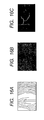
- Figs. 16A to 16C and Figs. 17A to 17C show examples.
- Figs. 16A and 17A are registered images of different fingers.
- Figs. 16B and 17B show the results of detecting the positions of wrinkles from these registered images.
- Figs. 16C and 17C show the results of detecting the positions of blood vessels.
- the amount and darkness of blood vessels in the image are evaluated in order to calculate the blood vessel level. It is also possible to evaluate the thickness of the blood vessel, the length of the blood vessel, the complexity of the blood vessel pattern, or the like in addition to this. It is also possible to evaluate the width of the wrinkle, the length of the wrinkles, or the like for calculating the wrinkle level other than the amount and darkness of wrinkles. It is possible to implement a more accurate identification suitability evaluation by increasing feature amounts used for evaluation and combining them appropriately.
- suitability for identification is evaluated from body surface information and blood vessel information based on the shot image, so that it is possible to implement stable identification that does not tend to be affected by variation over time even though the registered image is supposed to be used for a long time.
- a finger that false rejection does not occur in operating an identification system for a short time is called a finger suitable for identification.
- a finger suitable for identification For example, in the case of installing an identification device in a locker, a user often performs identification in a few hours after registration.
- Identification suitability evaluation according to a second embodiment is identification suitability evaluation for a short-term operation as described above.
- Equation (1) In identification suitability evaluation for a short-term operation, it is possible to use Equation (1) for calculating the identification suitability level shown in the first embodiment.
- the parameters m and n are readjusted for a short-term operation. More specifically, the tendency that false rejection does not occur is in advance studied on plural fingers for a short-term operation, and the parameters m and n are adjusted in such a way that the correlation between the tendency that false rejection does not occur and the identification suitability level of the subject fingers becomes high.
- Fig. 19 is an exemplary scatter diagram illustrating the relation between the matching rate and the identification suitability level of a finger on the day of registration. Data of about 40 fingers is on the scatter diagram of Fig. 19 .
- the vertical axis expresses the matching rate when identification is performed on the day of registration.
- the horizontal axis expresses the calculated identification suitability level based on Equation (1) described above.
- Equation (1) for calculating the identification suitability level of a finger can be used to evaluate suitability both for a long-term operation and for a short-term operation by changing only the parameters.
- This embodiment shows the description considering that the device is used for a short time.
- the parameters can be set appropriately for the device combining the techniques of the second embodiment and the first embodiment, or that the device is provided with at least two modes, a mode for a short-term use and a mode for a long-term use.
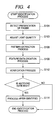
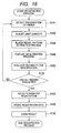
- Fig. 18 is an embodiment of a registration process flow using the process of evaluating the identification suitability of a finger (S120). In the following, procedures will be explained in which a finger the most suitable for identification is selected from plural user's fingers for registration candidates with reference to Fig. 18 .
- a user presents any one of fingers for registration candidates on the vein data capture device 2.
- the identification system performs the finger presentation detection process (S101) that determines whether a finger is presented on the device 2.
- the light quantity adjusting process (S103), the pattern extraction process (S108), and the feature data creation process (S109) are performed.
- the suitability of the presented finger is evaluated (S120).
- the identification system stores the evaluated result of suitability for identification (the identification suitability level) and feature data in the memory 12.
- the identification system again returns to the finger presentation detection process (S101).
- the user presents a second finger.
- the identification system in turn performs the finger presentation detection process (S101), the light quantity adjusting process (S103), the blood vessel pattern extraction process (S108), the feature data creation process (S109), and the process of evaluating the identification suitability of a finger (S120) for the second finger. After that, the evaluated result and feature data are stored in the memory 12. The flow from the process S101 to the process S120 in Fig. 18 are repeated until the evaluation of all the registration candidate fingers is completed. When the evaluation of all the registration candidate fingers is completed, the flow goes to a registered finger selection process (S130). In the registered finger selection process (S130), comparison is made for the identification suitability level of all the registration candidate fingers stored in the memory 12.
- a finger with the highest identification suitability level is determined as a registered finger.
- the feature data of the finger selected for a registered finger is stored (S126).
- information about the finger selected for a registered finger is presented to the user (S132). More specifically, the user is presented at which ordinal position the registered finger is presented on the device 2. In association with this presentation, it is also possible to present the evaluated result of the identification suitability of the registered finger or the evaluated result of the identification suitability of a finger other than the registered finger, for example.
- Fig. 20A is an exemplary image shot at the vein data capture device 2.
- Fig. 20B is an exemplary method of dividing an image.
- Fig. 20C is images divided according to the dividing method of Fig. 20B .
- the process of evaluating the identification suitability of a finger can also be performed for partial regions of a finger shown in Fig. 20C .
- the capacity of registration data can be made smaller while suppressing deterioration of identification accuracy.
- a process flow for reducing the capacity of registration data will be explained.
- the veins of a finger is shot in a wide area as shown in Fig. 20A .
- the image is divided to obtain plural partial images as shown in Fig. 20C .
- the partial images are evaluated for identification suitability to select one region with the highest identification suitability level from the plural partial images.
- feature data is created from the image of the selected region.
- the created feature data is stored in the storage device 14.
- the position (the coordinates) of the selected region is also stored in the storage device 14.
- data combining feature data and the position (the coordinates) is called registration data 220 ( Fig. 20F ).
- the veins of the entire finger are shot as similar to the registration process.
- An image on the same coordinates as the registration data is located is cut out of the shot identification image ( Fig. 20D ).
- Feature data for identification is created based on the cut image, and registration data is verified against identification data. It is determined whether the finger is the same finger or a different finger from the verified result, and the identification process is ended.
- Figs. 20A to 20F only one region with the highest identification suitability level is selected from four partial regions to create registration data. However, it is also possible to select a plurality of regions in order of descending identification suitability level for registration. In the identification process, plural items of identification data are created based on images of plural partial regions corresponding to the individual items of registration data to verify the corresponding regions against each other.
- False rejection sometimes occurs if an identification device is used for a long time.
- One of the causes is a change in the way to place a finger.
- a user can repeat almost the same way to place the finger when registered because the user remembers the way to place the finger when registered.
- the user forgets the way to place the finger when registered after a certain period elapses since the registration date, so that the user sometimes cannot repeat the same way to place the finger when registered.
- the users can present the finger at a correct position at the projection 21 for positioning.
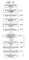
- Fig. 21 is an embodiment of an identification process flow for preventing false rejection. In the following, the identification process flow will be explained.
- the finger presentation detection process (S101), the light quantity adjusting process (S103), the pattern extraction process (S108), and the feature data creation process (S109) are performed.
- the verification process (S112) is performed to calculate the matching rate of images between when the finger is registered and when the finger is verified. If the calculated matching rate is lower than an identification threshold 33, it is determined that the finger is a different finger. If it is determined that the finger is a different finger, the result is presented to the user, and the identification process is ended. If the calculated matching rate is the identification threshold or more, it is determined that the finger is the same finger. If it is determined that the finger is the same finger, the way to place the finger is evaluated (S140).
- a method can be used that positions of vein patterns are compared between registration data 220 and identification data 240 to calculate the amount of the position shift of the finger and the way to place the finger is determined depending on the size of the position shift.
- the matching rate calculated in the verification process S112 If a change between the way to place the finger when registered and the way when verified is small, the calculated matching rate also takes a high value in the verification process. If the way to place the finger changes greatly, the matching rate is low. Thus, it is possible to evaluate the way to place the finger when verified using the matching rate.
- the matching rate is higher than a threshold 45 for evaluating the way to place the finger, it is determined that the finger is placed in almost the same way to place the finger when registered, whereas if the matching rate is lower than threshold 45, it is determined that the way to place the finger greatly changes. It is noted that the threshold 45 for evaluating the way to place the finger is set higher than the identification threshold 33.
- Fig. 22 shows the measurements of the verified result (the matching rate) in using an identification system adopting the evaluation of the way to place the finger according to this embodiment for a long time.
- the vertical axis expresses the matching rate, and the horizontal axis expresses the number of days since the registration date.
- the matching rate of a single finger was recorded for two months.
- An identification threshold 33 of the identification system for use in measurements was set to a matching rate of 70%.
- a threshold 45 for evaluating the way to place the finger was set to a matching rate of 75%. It is noted that the identification system for use in measurements gives an alarm in sounds to a subject when the matching rate is below the threshold 45 for evaluating the way to place the finger.
- a day indicated by a circle is a day that the matching rate is below the threshold 45 for evaluating the way to place the finger. An alarm is given to the user this day. It was confirmed from the graph of Fig. 22 that the matching rate tends to become high after an alarm is given. Thus, it was confirmed that it is useful to evaluate the way to place the finger and to present the result to the user in order to prevent the matching rate from reducing.
- the way to place the finger is evaluated and the result is presented to the user, so that the user can notice that the way to place the finger changes from the way when registered.
- the user places the finger carefully, or the user again registers the finger, so that it is possible to prevent false rejection from occurring.
- the identification device according to the present invention can be applied to a mobile device such as a mobile telephone terminal, a personal digital assistant (PDA), and a personal computer (PC), a safe, a locker, an automobile, and an access control device.
- a mobile device such as a mobile telephone terminal, a personal digital assistant (PDA), and a personal computer (PC), a safe, a locker, an automobile, and an access control device.
- PDA personal digital assistant
- PC personal computer
- the embodiments are examples, and it is without saying that the present invention is not limited to the foregoing embodiments.
Landscapes
- Engineering & Computer Science (AREA)
- Quality & Reliability (AREA)
- Physics & Mathematics (AREA)
- General Physics & Mathematics (AREA)
- Multimedia (AREA)
- Theoretical Computer Science (AREA)
- Measurement Of The Respiration, Hearing Ability, Form, And Blood Characteristics Of Living Organisms (AREA)
- Collating Specific Patterns (AREA)
- Image Input (AREA)
Applications Claiming Priority (1)
| Application Number | Priority Date | Filing Date | Title |
|---|---|---|---|
| JP2010253386A JP5690556B2 (ja) | 2010-11-12 | 2010-11-12 | 個人認証装置 |
Publications (3)
| Publication Number | Publication Date |
|---|---|
| EP2453385A2 true EP2453385A2 (de) | 2012-05-16 |
| EP2453385A3 EP2453385A3 (de) | 2014-11-19 |
| EP2453385B1 EP2453385B1 (de) | 2021-04-28 |
Family
ID=45476253
Family Applications (1)
| Application Number | Title | Priority Date | Filing Date |
|---|---|---|---|
| EP11008757.4A Active EP2453385B1 (de) | 2010-11-12 | 2011-11-03 | Vorrichtung und Verfahren zur Personenidentifizierung |
Country Status (3)
| Country | Link |
|---|---|
| EP (1) | EP2453385B1 (de) |
| JP (1) | JP5690556B2 (de) |
| CN (1) | CN102592110B (de) |
Cited By (3)
| Publication number | Priority date | Publication date | Assignee | Title |
|---|---|---|---|---|
| JP2013246527A (ja) * | 2012-05-24 | 2013-12-09 | Hitachi Ltd | 静脈認証装置および静脈認証方法 |
| EP4270297A4 (de) * | 2020-12-22 | 2024-04-17 | Sony Group Corporation | Informationsverarbeitungsvorrichtung, -verfahren und -programm |
| US12067095B2 (en) | 2018-10-03 | 2024-08-20 | Hitachi, Ltd. | Biometric authentication system, biometric authentication method, and storage medium |
Families Citing this family (9)
| Publication number | Priority date | Publication date | Assignee | Title |
|---|---|---|---|---|
| CN104584070A (zh) * | 2012-08-28 | 2015-04-29 | 株式会社日立制作所 | 认证装置以及认证方法 |
| JP2015014909A (ja) * | 2013-07-05 | 2015-01-22 | 日立オムロンターミナルソリューションズ株式会社 | 生体認証装置、情報処理装置 |
| JP2015228146A (ja) * | 2014-06-02 | 2015-12-17 | 株式会社 日立産業制御ソリューションズ | 静脈認証装置、静脈認証方法および静脈認証プログラム |
| JP6404011B2 (ja) * | 2014-06-25 | 2018-10-10 | 株式会社日立製作所 | 生体情報を利用する認証システム |
| CN105139008A (zh) * | 2015-10-09 | 2015-12-09 | 上海古鳌电子科技股份有限公司 | 指静脉认证系统 |
| JP6751072B2 (ja) * | 2017-12-27 | 2020-09-02 | 株式会社日立製作所 | 生体認証システム |
| CN107967466A (zh) * | 2018-01-03 | 2018-04-27 | 深圳市句点志能电子有限公司 | 一种突显血管的图像处理算法 |
| JP7366360B2 (ja) * | 2019-05-15 | 2023-10-23 | 株式会社日本マイクロニクス | 血管特定装置及び血管特定方法 |
| CN110378267B (zh) * | 2019-07-09 | 2021-07-20 | Oppo广东移动通信有限公司 | 静脉认证方法、装置、介质及电子设备 |
Citations (2)
| Publication number | Priority date | Publication date | Assignee | Title |
|---|---|---|---|---|
| JP2004265269A (ja) | 2003-03-04 | 2004-09-24 | Hitachi Ltd | 個人認証装置 |
| JP2009172064A (ja) | 2008-01-22 | 2009-08-06 | Panasonic Corp | 血管位置提示装置および血管位置提示方法 |
Family Cites Families (11)
| Publication number | Priority date | Publication date | Assignee | Title |
|---|---|---|---|---|
| JP3869545B2 (ja) * | 1998-01-19 | 2007-01-17 | 株式会社日立製作所 | 指の特徴パターン特徴検出装置及び個人識別装置 |
| JP4207717B2 (ja) * | 2003-08-26 | 2009-01-14 | 株式会社日立製作所 | 個人認証装置 |
| GB2426580C (en) * | 2004-06-18 | 2007-03-07 | Kyushu Intitute Of Technology | Personal identification method by subcutaneous bloodstream measurement and personal identification device. |
| JP4671811B2 (ja) * | 2004-11-05 | 2011-04-20 | 日立オートモティブシステムズ株式会社 | 指認証装置 |
| JP4466529B2 (ja) * | 2004-11-15 | 2010-05-26 | 日本電気株式会社 | 生体特徴入力装置 |
| JP4038777B2 (ja) * | 2006-02-28 | 2008-01-30 | ソニー株式会社 | 登録装置及び認証装置 |
| CN100453040C (zh) * | 2007-01-23 | 2009-01-21 | 天津理工大学 | 基于人体手背皮下静脉血管特征的身份识别仪及识别方法 |
| JP4882794B2 (ja) * | 2007-02-26 | 2012-02-22 | ソニー株式会社 | 画像判定装置、画像判定方法及びプログラム |
| JP5184279B2 (ja) * | 2008-09-24 | 2013-04-17 | 株式会社日立ソリューションズ | 指静脈認証システム |
| JP5079727B2 (ja) * | 2009-03-27 | 2012-11-21 | 株式会社日立ソリューションズ | 静脈認証装置における登録静脈画像作成方法及び装置 |
| JP4897014B2 (ja) * | 2009-06-24 | 2012-03-14 | 株式会社日立製作所 | 個人認証装置 |
-
2010
- 2010-11-12 JP JP2010253386A patent/JP5690556B2/ja active Active
-
2011
- 2011-11-03 EP EP11008757.4A patent/EP2453385B1/de active Active
- 2011-11-11 CN CN201110356730.1A patent/CN102592110B/zh active Active
Patent Citations (2)
| Publication number | Priority date | Publication date | Assignee | Title |
|---|---|---|---|---|
| JP2004265269A (ja) | 2003-03-04 | 2004-09-24 | Hitachi Ltd | 個人認証装置 |
| JP2009172064A (ja) | 2008-01-22 | 2009-08-06 | Panasonic Corp | 血管位置提示装置および血管位置提示方法 |
Cited By (3)
| Publication number | Priority date | Publication date | Assignee | Title |
|---|---|---|---|---|
| JP2013246527A (ja) * | 2012-05-24 | 2013-12-09 | Hitachi Ltd | 静脈認証装置および静脈認証方法 |
| US12067095B2 (en) | 2018-10-03 | 2024-08-20 | Hitachi, Ltd. | Biometric authentication system, biometric authentication method, and storage medium |
| EP4270297A4 (de) * | 2020-12-22 | 2024-04-17 | Sony Group Corporation | Informationsverarbeitungsvorrichtung, -verfahren und -programm |
Also Published As
| Publication number | Publication date |
|---|---|
| EP2453385B1 (de) | 2021-04-28 |
| EP2453385A3 (de) | 2014-11-19 |
| CN102592110B (zh) | 2016-03-09 |
| JP5690556B2 (ja) | 2015-03-25 |
| JP2012100957A (ja) | 2012-05-31 |
| CN102592110A (zh) | 2012-07-18 |
Similar Documents
| Publication | Publication Date | Title |
|---|---|---|
| EP2453385B1 (de) | Vorrichtung und Verfahren zur Personenidentifizierung | |
| JP5144461B2 (ja) | 指静脈認証装置、及び個人認証装置 | |
| KR101947538B1 (ko) | 인증 장치, 및 인증 방법 | |
| TWI381319B (zh) | Refers to the intravenous authentication device | |
| EP2848196B1 (de) | Gerät zur Erzeugung von Aufnahmen der Blutgefässe | |
| US11837029B2 (en) | Biometric authentication device and biometric authentication method | |
| US7616295B2 (en) | Biometric identification apparatus | |
| KR101436786B1 (ko) | 위조 지문 판별 장치 및 방법 | |
| EP2172911A2 (de) | Authentifizierungsvorrichtung | |
| JP2005071118A (ja) | 個人認証装置及び方法 | |
| JP5982311B2 (ja) | 血管画像撮影装置 | |
| JP4207937B2 (ja) | 個人認証装置 | |
| CN100423018C (zh) | 个人识别方法和设备 | |
| JP2011100317A (ja) | 指の屈伸運動時の静脈パターンを利用した個人認証方法及び個人認証システム | |
| JP2013061946A (ja) | 指静脈認証装置 | |
| JP4760870B2 (ja) | 個人認証装置及び方法 | |
| JP6071967B2 (ja) | 血管画像撮影装置 | |
| JP5751269B2 (ja) | 個人認証装置及び方法 | |
| JP2011065659A (ja) | 個人認証装置及び方法 | |
| KR100607577B1 (ko) | 광학식 지문취득 장치의 모조지문 판별방법 및 장치 | |
| JP6101723B2 (ja) | 個人認証装置及び方法 | |
| JP5624110B2 (ja) | 生体認証装置 | |
| JP2006318374A (ja) | 眼鏡判別装置および認証装置ならびに眼鏡判別方法 | |
| JP2004326820A (ja) | 指紋入力装置 |
Legal Events
| Date | Code | Title | Description |
|---|---|---|---|
| PUAI | Public reference made under article 153(3) epc to a published international application that has entered the european phase |
Free format text: ORIGINAL CODE: 0009012 |
|
| 17P | Request for examination filed |
Effective date: 20120305 |
|
| AK | Designated contracting states |
Kind code of ref document: A2 Designated state(s): AL AT BE BG CH CY CZ DE DK EE ES FI FR GB GR HR HU IE IS IT LI LT LU LV MC MK MT NL NO PL PT RO RS SE SI SK SM TR |
|
| AX | Request for extension of the european patent |
Extension state: BA ME |
|
| PUAL | Search report despatched |
Free format text: ORIGINAL CODE: 0009013 |
|
| AK | Designated contracting states |
Kind code of ref document: A3 Designated state(s): AL AT BE BG CH CY CZ DE DK EE ES FI FR GB GR HR HU IE IS IT LI LT LU LV MC MK MT NL NO PL PT RO RS SE SI SK SM TR |
|
| AX | Request for extension of the european patent |
Extension state: BA ME |
|
| RIC1 | Information provided on ipc code assigned before grant |
Ipc: G06K 9/00 20060101AFI20141013BHEP Ipc: G06K 9/03 20060101ALI20141013BHEP |
|
| RAP1 | Party data changed (applicant data changed or rights of an application transferred) |
Owner name: HITACHI INDUSTRY & CONTROL SOLUTIONS, LTD. |
|
| STAA | Information on the status of an ep patent application or granted ep patent |
Free format text: STATUS: EXAMINATION IS IN PROGRESS |
|
| 17Q | First examination report despatched |
Effective date: 20190528 |
|
| GRAP | Despatch of communication of intention to grant a patent |
Free format text: ORIGINAL CODE: EPIDOSNIGR1 |
|
| STAA | Information on the status of an ep patent application or granted ep patent |
Free format text: STATUS: GRANT OF PATENT IS INTENDED |
|
| INTG | Intention to grant announced |
Effective date: 20201222 |
|
| GRAS | Grant fee paid |
Free format text: ORIGINAL CODE: EPIDOSNIGR3 |
|
| GRAA | (expected) grant |
Free format text: ORIGINAL CODE: 0009210 |
|
| STAA | Information on the status of an ep patent application or granted ep patent |
Free format text: STATUS: THE PATENT HAS BEEN GRANTED |
|
| AK | Designated contracting states |
Kind code of ref document: B1 Designated state(s): AL AT BE BG CH CY CZ DE DK EE ES FI FR GB GR HR HU IE IS IT LI LT LU LV MC MK MT NL NO PL PT RO RS SE SI SK SM TR |
|
| REG | Reference to a national code |
Ref country code: GB Ref legal event code: FG4D |
|
| REG | Reference to a national code |
Ref country code: CH Ref legal event code: EP |
|
| REG | Reference to a national code |
Ref country code: DE Ref legal event code: R096 Ref document number: 602011070800 Country of ref document: DE |
|
| REG | Reference to a national code |
Ref country code: AT Ref legal event code: REF Ref document number: 1387916 Country of ref document: AT Kind code of ref document: T Effective date: 20210515 |
|
| REG | Reference to a national code |
Ref country code: IE Ref legal event code: FG4D |
|
| REG | Reference to a national code |
Ref country code: LT Ref legal event code: MG9D |
|
| REG | Reference to a national code |
Ref country code: AT Ref legal event code: MK05 Ref document number: 1387916 Country of ref document: AT Kind code of ref document: T Effective date: 20210428 |
|
| PG25 | Lapsed in a contracting state [announced via postgrant information from national office to epo] |
Ref country code: BG Free format text: LAPSE BECAUSE OF FAILURE TO SUBMIT A TRANSLATION OF THE DESCRIPTION OR TO PAY THE FEE WITHIN THE PRESCRIBED TIME-LIMIT Effective date: 20210728 Ref country code: AT Free format text: LAPSE BECAUSE OF FAILURE TO SUBMIT A TRANSLATION OF THE DESCRIPTION OR TO PAY THE FEE WITHIN THE PRESCRIBED TIME-LIMIT Effective date: 20210428 Ref country code: HR Free format text: LAPSE BECAUSE OF FAILURE TO SUBMIT A TRANSLATION OF THE DESCRIPTION OR TO PAY THE FEE WITHIN THE PRESCRIBED TIME-LIMIT Effective date: 20210428 Ref country code: LT Free format text: LAPSE BECAUSE OF FAILURE TO SUBMIT A TRANSLATION OF THE DESCRIPTION OR TO PAY THE FEE WITHIN THE PRESCRIBED TIME-LIMIT Effective date: 20210428 Ref country code: NL Free format text: LAPSE BECAUSE OF FAILURE TO SUBMIT A TRANSLATION OF THE DESCRIPTION OR TO PAY THE FEE WITHIN THE PRESCRIBED TIME-LIMIT Effective date: 20210428 Ref country code: FI Free format text: LAPSE BECAUSE OF FAILURE TO SUBMIT A TRANSLATION OF THE DESCRIPTION OR TO PAY THE FEE WITHIN THE PRESCRIBED TIME-LIMIT Effective date: 20210428 |
|
| REG | Reference to a national code |
Ref country code: DE Ref legal event code: R079 Ref document number: 602011070800 Country of ref document: DE Free format text: PREVIOUS MAIN CLASS: G06K0009000000 Ipc: G06V0010000000 |
|
| PG25 | Lapsed in a contracting state [announced via postgrant information from national office to epo] |
Ref country code: RS Free format text: LAPSE BECAUSE OF FAILURE TO SUBMIT A TRANSLATION OF THE DESCRIPTION OR TO PAY THE FEE WITHIN THE PRESCRIBED TIME-LIMIT Effective date: 20210428 Ref country code: SE Free format text: LAPSE BECAUSE OF FAILURE TO SUBMIT A TRANSLATION OF THE DESCRIPTION OR TO PAY THE FEE WITHIN THE PRESCRIBED TIME-LIMIT Effective date: 20210428 Ref country code: IS Free format text: LAPSE BECAUSE OF FAILURE TO SUBMIT A TRANSLATION OF THE DESCRIPTION OR TO PAY THE FEE WITHIN THE PRESCRIBED TIME-LIMIT Effective date: 20210828 Ref country code: GR Free format text: LAPSE BECAUSE OF FAILURE TO SUBMIT A TRANSLATION OF THE DESCRIPTION OR TO PAY THE FEE WITHIN THE PRESCRIBED TIME-LIMIT Effective date: 20210729 Ref country code: LV Free format text: LAPSE BECAUSE OF FAILURE TO SUBMIT A TRANSLATION OF THE DESCRIPTION OR TO PAY THE FEE WITHIN THE PRESCRIBED TIME-LIMIT Effective date: 20210428 Ref country code: PL Free format text: LAPSE BECAUSE OF FAILURE TO SUBMIT A TRANSLATION OF THE DESCRIPTION OR TO PAY THE FEE WITHIN THE PRESCRIBED TIME-LIMIT Effective date: 20210428 Ref country code: PT Free format text: LAPSE BECAUSE OF FAILURE TO SUBMIT A TRANSLATION OF THE DESCRIPTION OR TO PAY THE FEE WITHIN THE PRESCRIBED TIME-LIMIT Effective date: 20210830 Ref country code: NO Free format text: LAPSE BECAUSE OF FAILURE TO SUBMIT A TRANSLATION OF THE DESCRIPTION OR TO PAY THE FEE WITHIN THE PRESCRIBED TIME-LIMIT Effective date: 20210728 Ref country code: ES Free format text: LAPSE BECAUSE OF FAILURE TO SUBMIT A TRANSLATION OF THE DESCRIPTION OR TO PAY THE FEE WITHIN THE PRESCRIBED TIME-LIMIT Effective date: 20210428 |
|
| REG | Reference to a national code |
Ref country code: NL Ref legal event code: MP Effective date: 20210428 |
|
| PG25 | Lapsed in a contracting state [announced via postgrant information from national office to epo] |
Ref country code: RO Free format text: LAPSE BECAUSE OF FAILURE TO SUBMIT A TRANSLATION OF THE DESCRIPTION OR TO PAY THE FEE WITHIN THE PRESCRIBED TIME-LIMIT Effective date: 20210428 Ref country code: EE Free format text: LAPSE BECAUSE OF FAILURE TO SUBMIT A TRANSLATION OF THE DESCRIPTION OR TO PAY THE FEE WITHIN THE PRESCRIBED TIME-LIMIT Effective date: 20210428 Ref country code: DK Free format text: LAPSE BECAUSE OF FAILURE TO SUBMIT A TRANSLATION OF THE DESCRIPTION OR TO PAY THE FEE WITHIN THE PRESCRIBED TIME-LIMIT Effective date: 20210428 Ref country code: CZ Free format text: LAPSE BECAUSE OF FAILURE TO SUBMIT A TRANSLATION OF THE DESCRIPTION OR TO PAY THE FEE WITHIN THE PRESCRIBED TIME-LIMIT Effective date: 20210428 Ref country code: SM Free format text: LAPSE BECAUSE OF FAILURE TO SUBMIT A TRANSLATION OF THE DESCRIPTION OR TO PAY THE FEE WITHIN THE PRESCRIBED TIME-LIMIT Effective date: 20210428 Ref country code: SK Free format text: LAPSE BECAUSE OF FAILURE TO SUBMIT A TRANSLATION OF THE DESCRIPTION OR TO PAY THE FEE WITHIN THE PRESCRIBED TIME-LIMIT Effective date: 20210428 |
|
| REG | Reference to a national code |
Ref country code: DE Ref legal event code: R097 Ref document number: 602011070800 Country of ref document: DE |
|
| PLBE | No opposition filed within time limit |
Free format text: ORIGINAL CODE: 0009261 |
|
| STAA | Information on the status of an ep patent application or granted ep patent |
Free format text: STATUS: NO OPPOSITION FILED WITHIN TIME LIMIT |
|
| 26N | No opposition filed |
Effective date: 20220131 |
|
| PG25 | Lapsed in a contracting state [announced via postgrant information from national office to epo] |
Ref country code: IS Free format text: LAPSE BECAUSE OF FAILURE TO SUBMIT A TRANSLATION OF THE DESCRIPTION OR TO PAY THE FEE WITHIN THE PRESCRIBED TIME-LIMIT Effective date: 20210828 Ref country code: AL Free format text: LAPSE BECAUSE OF FAILURE TO SUBMIT A TRANSLATION OF THE DESCRIPTION OR TO PAY THE FEE WITHIN THE PRESCRIBED TIME-LIMIT Effective date: 20210428 |
|
| PG25 | Lapsed in a contracting state [announced via postgrant information from national office to epo] |
Ref country code: MC Free format text: LAPSE BECAUSE OF FAILURE TO SUBMIT A TRANSLATION OF THE DESCRIPTION OR TO PAY THE FEE WITHIN THE PRESCRIBED TIME-LIMIT Effective date: 20210428 |
|
| REG | Reference to a national code |
Ref country code: CH Ref legal event code: PL |
|
| PG25 | Lapsed in a contracting state [announced via postgrant information from national office to epo] |
Ref country code: LU Free format text: LAPSE BECAUSE OF NON-PAYMENT OF DUE FEES Effective date: 20211103 Ref country code: IT Free format text: LAPSE BECAUSE OF FAILURE TO SUBMIT A TRANSLATION OF THE DESCRIPTION OR TO PAY THE FEE WITHIN THE PRESCRIBED TIME-LIMIT Effective date: 20210428 Ref country code: BE Free format text: LAPSE BECAUSE OF NON-PAYMENT OF DUE FEES Effective date: 20211130 |
|
| REG | Reference to a national code |
Ref country code: BE Ref legal event code: MM Effective date: 20211130 |
|
| PG25 | Lapsed in a contracting state [announced via postgrant information from national office to epo] |
Ref country code: LI Free format text: LAPSE BECAUSE OF NON-PAYMENT OF DUE FEES Effective date: 20211130 Ref country code: CH Free format text: LAPSE BECAUSE OF NON-PAYMENT OF DUE FEES Effective date: 20211130 |
|
| PG25 | Lapsed in a contracting state [announced via postgrant information from national office to epo] |
Ref country code: IE Free format text: LAPSE BECAUSE OF NON-PAYMENT OF DUE FEES Effective date: 20211103 |
|
| PG25 | Lapsed in a contracting state [announced via postgrant information from national office to epo] |
Ref country code: HU Free format text: LAPSE BECAUSE OF FAILURE TO SUBMIT A TRANSLATION OF THE DESCRIPTION OR TO PAY THE FEE WITHIN THE PRESCRIBED TIME-LIMIT; INVALID AB INITIO Effective date: 20111103 Ref country code: CY Free format text: LAPSE BECAUSE OF FAILURE TO SUBMIT A TRANSLATION OF THE DESCRIPTION OR TO PAY THE FEE WITHIN THE PRESCRIBED TIME-LIMIT Effective date: 20210428 |
|
| PG25 | Lapsed in a contracting state [announced via postgrant information from national office to epo] |
Ref country code: MK Free format text: LAPSE BECAUSE OF FAILURE TO SUBMIT A TRANSLATION OF THE DESCRIPTION OR TO PAY THE FEE WITHIN THE PRESCRIBED TIME-LIMIT Effective date: 20210428 |
|
| PG25 | Lapsed in a contracting state [announced via postgrant information from national office to epo] |
Ref country code: MT Free format text: LAPSE BECAUSE OF FAILURE TO SUBMIT A TRANSLATION OF THE DESCRIPTION OR TO PAY THE FEE WITHIN THE PRESCRIBED TIME-LIMIT Effective date: 20210428 |
|
| PGFP | Annual fee paid to national office [announced via postgrant information from national office to epo] |
Ref country code: DE Payment date: 20241001 Year of fee payment: 14 |
|
| PGFP | Annual fee paid to national office [announced via postgrant information from national office to epo] |
Ref country code: GB Payment date: 20241002 Year of fee payment: 14 |
|
| PGFP | Annual fee paid to national office [announced via postgrant information from national office to epo] |
Ref country code: FR Payment date: 20241001 Year of fee payment: 14 |
|
| PG25 | Lapsed in a contracting state [announced via postgrant information from national office to epo] |
Ref country code: TR Free format text: LAPSE BECAUSE OF FAILURE TO SUBMIT A TRANSLATION OF THE DESCRIPTION OR TO PAY THE FEE WITHIN THE PRESCRIBED TIME-LIMIT Effective date: 20210428 |