EP2452760B1 - Machine à profiler et supports d'accouplement pour une telle machine - Google Patents
Machine à profiler et supports d'accouplement pour une telle machine Download PDFInfo
- Publication number
- EP2452760B1 EP2452760B1 EP20100014654 EP10014654A EP2452760B1 EP 2452760 B1 EP2452760 B1 EP 2452760B1 EP 20100014654 EP20100014654 EP 20100014654 EP 10014654 A EP10014654 A EP 10014654A EP 2452760 B1 EP2452760 B1 EP 2452760B1
- Authority
- EP
- European Patent Office
- Prior art keywords
- coupling
- profiling machine
- counterparts
- stands
- working
- Prior art date
- Legal status (The legal status is an assumption and is not a legal conclusion. Google has not performed a legal analysis and makes no representation as to the accuracy of the status listed.)
- Active
Links
Images

Classifications
-
- B—PERFORMING OPERATIONS; TRANSPORTING
- B21—MECHANICAL METAL-WORKING WITHOUT ESSENTIALLY REMOVING MATERIAL; PUNCHING METAL
- B21D—WORKING OR PROCESSING OF SHEET METAL OR METAL TUBES, RODS OR PROFILES WITHOUT ESSENTIALLY REMOVING MATERIAL; PUNCHING METAL
- B21D5/00—Bending sheet metal along straight lines, e.g. to form simple curves
- B21D5/06—Bending sheet metal along straight lines, e.g. to form simple curves by drawing procedure making use of dies or forming-rollers, e.g. making profiles
- B21D5/08—Bending sheet metal along straight lines, e.g. to form simple curves by drawing procedure making use of dies or forming-rollers, e.g. making profiles making use of forming-rollers
Definitions
- the invention relates to a coupling stand for a profiling machine for longitudinally forming a metal strip or initial profile in a profile or tube by means of a plurality of Rollumformtechnikmaschineen according to the preamble of claim 1, and a profiling machine with such coupling stands and a corresponding method.
- At least part of the roll forming tools of a profiling machine of the present type is combined to form a plurality of tool groups arranged one behind the other in the working direction, each of which is held in a frame and forms a forming station with it. At least a part of the rolling forming tools arranged in a forming station is seated on work shafts mounted in the frame, which are provided with coupling elements leading out laterally from the stand.
- clutch stand are arranged, on the one hand have coupling counterparts to the coupling elements of the working shafts and on the other hand connections for a drive system of the profiling to transmit torque from the drive system to the working shafts.
- the coupling elements of the working shafts are usually made of coupling pins or sleeves, while the coupling stand is equipped with sleeves or pins which engage positively in the coupling pins or sleeves of the working shafts.
- the torque transmission is usually carried out by means of variable length propeller shafts.
- Profiling machines are able to produce virtually endless profiles or tubes of various cross-sectional shapes from a metal strip or an output profile.
- a multiplicity of roll forming tools are used for this purpose, which are grouped together in typically 20 to 30 forming stations arranged in line one behind the other. If a different profile shape is to be produced on one and the same profiling machine, a multiplicity of roll forming tools must accordingly be exchanged.
- a coupling stand is provided in a profiling machine of the type described above between the forming stations and the drive system, which can engage and disengage the working shafts, so that the roll forming tools together with their working shafts can be exchanged as a unit, without having to move the framework relative to the machine base or with respect to a framework support plate.
- An exchange of the roll forming tools without subsequent lengthy adjustments, especially in the axis parallel to the working waves direction, is possible by the previous uncoupling of the drive system. This saves time when converting a Profiliermaschine to another profile shape and thus reduces adverse production stoppages.
- a profiling machine of the present type is in the EP 0 365 976 B1 described.
- laterally movable clutch stand together move away from the forming rollers to release the working shafts. After replacing them, the coupling stands are again almost to their engaged initial position to the forming stations moved up and determined the possibly changed installation height of the working shafts. Then the coupling counterparts are moved vertically on the coupling uprights to adjust their height to the height of the respective working shaft.
- the clutch stands are further moved together to the forming stations to bring the coupling elements and the coupling counterparts into engagement, whereby the coupling process is terminated.
- a gear block of the drive system is moved with the coupling stands, or the changing distance between the coupling stands and the drive system is compensated by variable length drive shafts.
- the present invention seeks to provide improved coupling stand available to further improve a profiling machine of the type described above with regard to their flexibility, and to propose such an improved profiling machine and a corresponding method.
- the coupling stands are no longer displaceable only as a whole towards and away from the working shafts, but the coupling counterparts for the working shafts of the stands with their associated drive system connections are seated individually or in groups on separate coupling sections of the coupling stands according to the invention , These coupling sections are independently movable from each other. In this case, alla Kupplungsabsuhnitte can be moved separately be. However, if only two coupling sections are involved, it may be implemented so that one coupling section is movable independently of the remainder of the coupling stand while the other coupling section is moved together with the remainder of the coupling stand; In this case, the clutch stand as a whole, as was the case in the prior art, would be movable.
- the coupling stand may comprise a stationary support member having two or more coupling sections mounted movably thereon so that ultimately only the coupling sections move to couple or uncouple individual working shafts while the support member the coupling stand is arranged stationary relative to the associated frame and carries guides and the drives for the movable coupling sections.
- the Ankuppelvorgang took place so far, for example, in the prior art after the EP 0 365 976 B1 as described above by axial nesting of the coupling elements and the coupling counterparts on the working shafts or on the coupling stanchions, so that they then interlock and can transmit a torque.
- the coupling counterparts are in turn connected to the drive system.
- the overload protection by the pneumatic drive of the coupling sections not only replaces the previous overload protection by resilient coupling elements and coupling counterparts when coupling, but also provides in the opposite direction, ie when uncoupling, an overload protection.
- the coupling elements and the coupling counterparts can often not be separated from each other, since they are braced against each other in the direction of rotation.
- the existing by the pneumatic drive overload protection prevents this, that the coupling stand or the coupling section pulls obliquely, because about the coupling elements and coupling counterparts do not come apart.
- the pneumatic drive brings only a resilient bias on the clutch stand, so that it moves only when the coupling elements and the coupling counterparts separate from each other, for example by a short reversing of the drive system or by a manually applied vibration.
- the coupling stand of the profiling machine according to the invention are provided with vertical drive devices for changing the height of the coupling counterparts, these vertical drive devices are preferably also pneumatic actuators.
- the vertical drive devices can be used to adjust the vertical position of the coupling counterparts in the coupling stand to approximately changed vertical positions of the working shafts, for example when the roll forming tools of the forming station have been replaced.
- the coupling counterparts and / or the coupling elements are each end provided with insertion aids, in particular with conically shaped end pieces.
- the coupling elements are designed as coupling sleeves, and the coupling counterparts as coupling sleeves which can be positively inserted into these sleeves, this can be realized in this way; that the coupling pins are provided at the end with a cylindrical end piece whose outer circumference is smaller than the outer circumference of the form-locking elements of the coupling pin, and in that the coupling sleeves are provided at the end with a conically shaped insertion section.
- the present invention is preferably further developed such that the coupling counterpart and the associated connection for the drive system sitting in a bearing in the coupling portion which is spring-loaded slightly orthogonal to the working shaft axis movable; It can therefore be moved horizontally by a millimeter against a spring force, for example, to bring the coupling element of the respective working shaft with the coupling counterpart of the coupling stand exactly in alignment.
- the spring-loaded displaceability of the bearing in the coupling sections greatly facilitates the coupling process.
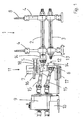
- FIGS. 1 and 2 show in a schematic cross section and a perspective view of the same part of an inventively designed profiling, namely a forming station 1 with an upper working shaft 2 and a lower working shaft 3, which serve for receiving and storing (not shown here) Rollumformwerkmaschineen.
- the two working waves 2, 3 are mounted vertically displaceable in a frame 4.
- the framework 4 is fixedly attached to a (not shown) machine frame.
- the working shafts 2, 3 can be vertically adjusted in the frame 4 in order to adapt to different Rollumformwerkmaschinemaschinee can.
- a transmission block 9 of a drive system is arranged on a gear carrier 10, from which a torque is to be transmitted to the working shafts 2, 3. This is done via two propeller shafts 15, which connect the gear block 9 with the working shafts 2, 3 torsionally rigid.
- a coupling stand 11 is arranged, with the aid of the propeller shafts 15, and thus the transmission block 9 of the drive system, coupled to the working shafts 2, 3 of the forming station 1 or decoupled from them can be without having to move the gear block 9 or the frame 4.
- the working shafts 2, 3 run out towards the gear block beyond the framework 4 into coupling elements 13, of which in the present illustration only the lower coupling element 13 is visible, and which are designed here as coupling pins.
- the coupling stand 11 has two coupling sections, an upper coupling section 5 and a lower coupling section 6, each in a bearing housing 14 to the frame 4 towards a (not visible here) coupling counterpart 12, namely a coupling sleeve for the coupling element 13, and on the opposite Side, the transmission block 9 through, in each case one, designed as a telescopically length-adjustable propeller shaft 15 formed connection for the transmission block 9.
- the torque from the transmission block 9 is thus transmitted via the propeller shafts 15 and the coupling counterparts 12 designed as a coupling sleeve, which are mounted in the bearing housing 14, on the coupling elements 13 designed as a coupling pin and thus on the working shafts 2, 3.
- the upper working shaft 2 of the present embodiment is coupled to the transmission block 9 and thus to the drive system of the profiling machine, while the lower working shaft 3 is uncoupled.
- This movement of the two coupling sections 5 and 6 is effected by an upper 16 and a lower pneumatic cylinder 17, the piston rods 18, the respective coupling sections 5, 6 move, and supported on height-adjustable on the support member 7 mounted support plates 19.
- sliding rails 20, 21 are provided which are slidably held in corresponding receptacles of the support plates 19.
- the mounted in the bearing housing 14 coupling counterparts 12 can move within the bearing housing 14 by about 1 - 2 mm in an orthogonal to the axes of the working shafts 2, 3, so that a small offset of the working shaft axis to the coupling counterpart 12 horizontally and / or vertically compensated can be and the engagement process is still possible. If the coupling elements 13 and / or the coupling counterparts 12 are provided with corresponding insertion bevels, the evasive movement of the coupling counterpart 12 in the bearing housing 14 can take place automatically.
- the flexibility of a profiling machine is significantly increased, and the preferred embodiments of the invention simplify and accelerate coupling and uncoupling operations, facilitating and thus supporting the use of increased flexibility.
Landscapes
- Engineering & Computer Science (AREA)
- Mechanical Engineering (AREA)
- Bending Of Plates, Rods, And Pipes (AREA)
- Automatic Assembly (AREA)
Claims (12)
- Colonne d'accouplement dévolue à une machine de profilage dédiée à la mise en forme longitudinale d'un ruban métallique ou d'un profilé de départ, au moyen d'une pluralité d'outils de formage par roulage, pour obtenir un profilé ou un tube,
caractérisée par le fait
qu'elle présente au moins deux zones d'accouplement (5, 6) portant, respectivement, au moins une pièce complémentaire d'accouplement (12) et l'élément de liaison (15) associé à ladite pièce et destiné au système d'entraînement (9) de la machine de profilage, au moins une zone d'accouplement (5) étant douée de mobilité distincte en vue d'accoupler audit système d'entraînement (9), ou de désaccoupler d'avec ce dernier, au moins un arbre de travail (2) d'un bâti (4) de ladite machine de profilage, indépendamment des autres arbres de travail (3). - Machine de profilage dédiée à la mise en forme longitudinale d'un ruban métallique ou d'un profilé de départ, au moyen d'une pluralité d'outils de formage par roulage, pour obtenir un profilé ou un tube,- sachant qu'au moins une partie desdits outils de formage par roulage est rassemblée en plusieurs groupes d'outils qui sont disposés les uns derrière les autres dans la direction de travail et sont retenus, à chaque fois, dans un bâti (4) avec lequel ils forment respectivement un poste de formage (1),- sachant qu'au moins une partie des outils de formage par roulage, situés dans un poste de formage (1), est calée sur des arbres de travail (2, 3) montés dans ledit bâti (4) et pourvus d'éléments d'accouplement (13) faisant saillie latéralement au-delà dudit bâti (4),- sachant que des colonnes d'accouplement (11) jouxtant les bâtis (4) comprennent, d'une part, des pièces d'accouplement (12) complémentaires desdits éléments d'accouplement (13) des arbres de travail (2, 3) et, d'autre part, des éléments de liaison (15) destinés à un système d'entraînement (9) de la machine de profilage, de manière à transmettre un couple de rotation auxdits arbres de travail (2, 3) à partir dudit système d'entraînement (9),- et sachant que, pour accoupler lesdits arbres de travail (2, 3) audit système d'entraînement (9) et les désaccoupler d'avec ce dernier, lesdites colonnes d'accouplement (11) sont douées, au moins par zones, de mobilité dans une direction de mouvement pointant vers lesdits bâtis (4) et s'en éloignant, en vue d'instaurer et de supprimer la venue en prise desdites pièces complémentaires d'accouplement (12) avec lesdits éléments d'accouplement (13) desdits arbres de travail (2, 3),
caractérisée par le fait- qu'elle comporte des colonnes d'accouplement (11) conformes à la revendication 1. - Machine de profilage selon la revendication 2,
caractérisée par le fait
que les zones mobiles d'accouplement (5, 6) des colonnes d'accouplement (11) peuvent être mues au moyen d'entraînements pneumatiques (16, 17). - Machine de profilage selon la revendication 3,
caractérisée par le fait
que les entraînements pneumatiques sont constitués, pour l'essentiel, d'au moins un vérin (16, 17) à commande pneumatique et d'un dispositif de guidage (20, 21) dédié aux zones d'accouplement (5, 6). - Machine de profilage selon au moins l'une des revendications 2 à 4,
caractérisée par le fait
que les colonnes d'accouplement (11) sont composées d'un élément stationnaire de support (7), et d'au moins deux zones d'accouplement (5, 6) implantées sur ledit élément avec faculté de mouvement. - Machine de profilage selon au moins l'une des revendications 2 à 5,
caractérisée par le fait
que les colonnes d'accouplement (11) sont munies de dispositifs d'entraînement vertical, en vue de faire varier la hauteur des zones d'accouplement (5, 6). - Machine de profilage selon la revendication 6,
caractérisée par le fait
que les dispositifs d'entraînement vertical se prêtent à l'exécution d'un va-et-vient vertical oscillatoire des zones d'accouplement (5, 6). - Machine de profilage selon la revendication 7,
caractérisée par le fait
que les éléments d'accouplement (13), et/ou les pièces complémentaires d'accouplement (12), sont pourvu(e)s d'auxiliaires d'insertion. - Machine de profilage selon la revendication 8,
caractérisée par le fait
que les éléments d'accouplement (13), et/ou les pièces complémentaires d'accouplement (12), sont pourvu(e)s de pièces d'extrémité de configuration conique. - Machine de profilage selon l'une des revendications 8 ou 9,
caractérisée par le fait
que les auxiliaires d'insertion comprennent une monture (14) de la pièce complémentaire d'accouplement (12) qui est douée de souplesse élastique, avec précontrainte par ressorts (22), perpendiculairement à l'axe de l'arbre de travail (2, 3) devant être accouplé. - Procédé de mise en forme longitudinale d'un ruban métallique ou d'un profilé de départ en vue d'obtenir un profilé ou un tube, au moyen d'une machine de profilage conforme à au moins l'une des revendications 2 à 10, les colonnes d'accouplement (11) de ladite machine étant mues, par zones (5, 6), en direction et à l'écart des bâtis (4) en vue de désaccoupler des arbres de travail individuels (2) ou des groupes d'arbres de travail d'avec le système d'entraînement (9), ou de les accoupler à ce dernier.
- Procédé selon la revendication 11,
caractérisé par le fait
qu'il est fait usage de colonnes d'accouplement (11) équipées de dispositifs d'entraînement vertical en vue de faire varier la hauteur des pièces complémentaires d'accouplement (12) ; et par le fait que la colonne d'accouplement (11) d'un poste de formage (1), devant être accouplé au système d'entraînement (9), imprime un va-et-vient vertical oscillatoire à au moins l'une desdites pièces complémentaires d'accouplement (12), alors que cette dernière est mue en direction du bâti (4), afin d'exécuter le processus d'accouplement.
Priority Applications (3)
| Application Number | Priority Date | Filing Date | Title |
|---|---|---|---|
| ES10014654T ES2403077T3 (es) | 2010-11-16 | 2010-11-16 | Máquina perfiladora y soporte de acoplamiento para una máquina de este tipo |
| EP20100014654 EP2452760B1 (fr) | 2010-11-16 | 2010-11-16 | Machine à profiler et supports d'accouplement pour une telle machine |
| DK10014654T DK2452760T3 (da) | 2010-11-16 | 2010-11-16 | Profileringsmaskine og koblingsstander til en sådan maskine |
Applications Claiming Priority (1)
| Application Number | Priority Date | Filing Date | Title |
|---|---|---|---|
| EP20100014654 EP2452760B1 (fr) | 2010-11-16 | 2010-11-16 | Machine à profiler et supports d'accouplement pour une telle machine |
Publications (2)
| Publication Number | Publication Date |
|---|---|
| EP2452760A1 EP2452760A1 (fr) | 2012-05-16 |
| EP2452760B1 true EP2452760B1 (fr) | 2013-02-20 |
Family
ID=45443217
Family Applications (1)
| Application Number | Title | Priority Date | Filing Date |
|---|---|---|---|
| EP20100014654 Active EP2452760B1 (fr) | 2010-11-16 | 2010-11-16 | Machine à profiler et supports d'accouplement pour une telle machine |
Country Status (3)
| Country | Link |
|---|---|
| EP (1) | EP2452760B1 (fr) |
| DK (1) | DK2452760T3 (fr) |
| ES (1) | ES2403077T3 (fr) |
Cited By (2)
| Publication number | Priority date | Publication date | Assignee | Title |
|---|---|---|---|---|
| WO2015085340A2 (fr) | 2013-12-10 | 2015-06-18 | Asmag-Holding Gmbh | Système d'entraînement et installation de profilage équipée de celui-ci |
| EP3311932A1 (fr) | 2016-10-21 | 2018-04-25 | DREISTERN GmbH & Co.KG | Profiliermaschine und kuppelvorrichtung für eine solche sowie ankuppelverfahren |
Families Citing this family (1)
| Publication number | Priority date | Publication date | Assignee | Title |
|---|---|---|---|---|
| DE102022120537B3 (de) | 2022-08-15 | 2023-11-30 | PROFILMETALL-Engineering GmbH | Kuppelvorrichtung und Rollformanlage |
Family Cites Families (3)
| Publication number | Priority date | Publication date | Assignee | Title |
|---|---|---|---|---|
| DE2732233C2 (de) * | 1977-07-16 | 1983-04-21 | Maschinen- Und Werkzeugbau Gmbh, 4600 Dortmund | Profiliermaschine |
| DE3836286A1 (de) | 1988-10-25 | 1990-04-26 | Krueckels Gerhard | Profiliermaschine |
| JP3362072B2 (ja) * | 1993-09-27 | 2003-01-07 | 株式会社中田製作所 | 冷間ロール成形機の駆動軸連結装置 |
-
2010
- 2010-11-16 ES ES10014654T patent/ES2403077T3/es active Active
- 2010-11-16 DK DK10014654T patent/DK2452760T3/da active
- 2010-11-16 EP EP20100014654 patent/EP2452760B1/fr active Active
Cited By (3)
| Publication number | Priority date | Publication date | Assignee | Title |
|---|---|---|---|---|
| WO2015085340A2 (fr) | 2013-12-10 | 2015-06-18 | Asmag-Holding Gmbh | Système d'entraînement et installation de profilage équipée de celui-ci |
| WO2015085340A3 (fr) * | 2013-12-10 | 2015-08-06 | Asmag-Holding Gmbh | Système d'entraînement et installation de profilage équipée de celui-ci |
| EP3311932A1 (fr) | 2016-10-21 | 2018-04-25 | DREISTERN GmbH & Co.KG | Profiliermaschine und kuppelvorrichtung für eine solche sowie ankuppelverfahren |
Also Published As
| Publication number | Publication date |
|---|---|
| ES2403077T3 (es) | 2013-05-14 |
| DK2452760T3 (da) | 2013-05-06 |
| EP2452760A1 (fr) | 2012-05-16 |
Similar Documents
| Publication | Publication Date | Title |
|---|---|---|
| EP3268144B1 (fr) | Machine à dresser et procédé de remplacement d'éléments de roulement à dresser | |
| AT515177B1 (de) | Antriebssystem sowie damit ausgerüstete Profilieranlage | |
| EP2450115A2 (fr) | Laminoir, cage de laminoir et procédé de changement de cages de laminoir dans un laminoir | |
| EP0685276B1 (fr) | Dispositif de transfert dans une machine de formage, en particulier dans une presse de transfert | |
| EP2452760B1 (fr) | Machine à profiler et supports d'accouplement pour une telle machine | |
| EP2781294B1 (fr) | Machine à souder, en particulier soudeuse de treillis, dotée d'au moins deux dispositifs de soudage mobiles | |
| DE2243534A1 (de) | Biegevorrichtung | |
| EP0323607B1 (fr) | Machine à forger en long pour forger des barres circulaires ou des barres à angles vifs | |
| EP0365976B1 (fr) | Machine de profilage | |
| EP1210995B1 (fr) | Machine pour l'usinage de pièces, notamment de tôles, avec au moins un dispositif de cintrage et un dispositif d'assemblage | |
| DE967373C (de) | Vertikalwalzengeruest | |
| EP3311932A1 (fr) | Profiliermaschine und kuppelvorrichtung für eine solche sowie ankuppelverfahren | |
| DE10015285C2 (de) | Walzstraße zum Walzen von metallischen Rohren, Stäben oder Drähten | |
| DE2732233C2 (de) | Profiliermaschine | |
| EP2251110A1 (fr) | Machine à profiler | |
| DE102014212732B4 (de) | Verfahren und Anstauchvorrichtung zum Herstellen von abgesetzten Werkstücken, wie Wellen oder Stäbe | |
| EP1849535A1 (fr) | Cage de laminoir | |
| EP2251112B1 (fr) | Machine à profiler et procédé de formage longitudinal d'une bande de métal ou d'un profil de départ dans un profil ou un tuyau | |
| EP0568854A2 (fr) | Procédé et accouplement rapide pour la connection d'un tracteur à un outil agricole | |
| WO2006045284A1 (fr) | Dispositif de changement d'outillage automatique | |
| EP3448594B1 (fr) | Presse-transfert pourvue d'un serre-flan en c | |
| DE102022120537B3 (de) | Kuppelvorrichtung und Rollformanlage | |
| WO2023116967A1 (fr) | Système de transfert à trois axes d'une presse de transfert | |
| DE2503284C3 (de) | Walzendrehbank | |
| DE60022731T2 (de) | Blechbiegevorrichtung |
Legal Events
| Date | Code | Title | Description |
|---|---|---|---|
| PUAI | Public reference made under article 153(3) epc to a published international application that has entered the european phase |
Free format text: ORIGINAL CODE: 0009012 |
|
| AK | Designated contracting states |
Kind code of ref document: A1 Designated state(s): AL AT BE BG CH CY CZ DE DK EE ES FI FR GB GR HR HU IE IS IT LI LT LU LV MC MK MT NL NO PL PT RO RS SE SI SK SM TR |
|
| AX | Request for extension of the european patent |
Extension state: BA ME |
|
| 17P | Request for examination filed |
Effective date: 20120702 |
|
| RIC1 | Information provided on ipc code assigned before grant |
Ipc: B21B 35/14 20060101ALI20120719BHEP Ipc: B21B 31/10 20060101ALI20120719BHEP Ipc: B21D 5/08 20060101AFI20120719BHEP |
|
| GRAP | Despatch of communication of intention to grant a patent |
Free format text: ORIGINAL CODE: EPIDOSNIGR1 |
|
| GRAS | Grant fee paid |
Free format text: ORIGINAL CODE: EPIDOSNIGR3 |
|
| GRAA | (expected) grant |
Free format text: ORIGINAL CODE: 0009210 |
|
| AK | Designated contracting states |
Kind code of ref document: B1 Designated state(s): AL AT BE BG CH CY CZ DE DK EE ES FI FR GB GR HR HU IE IS IT LI LT LU LV MC MK MT NL NO PL PT RO RS SE SI SK SM TR |
|
| REG | Reference to a national code |
Ref country code: GB Ref legal event code: FG4D Free format text: NOT ENGLISH |
|
| REG | Reference to a national code |
Ref country code: CH Ref legal event code: EP |
|
| REG | Reference to a national code |
Ref country code: AT Ref legal event code: REF Ref document number: 597308 Country of ref document: AT Kind code of ref document: T Effective date: 20130315 |
|
| REG | Reference to a national code |
Ref country code: IE Ref legal event code: FG4D Free format text: LANGUAGE OF EP DOCUMENT: GERMAN |
|
| REG | Reference to a national code |
Ref country code: DE Ref legal event code: R096 Ref document number: 502010002340 Country of ref document: DE Effective date: 20130418 |
|
| REG | Reference to a national code |
Ref country code: DK Ref legal event code: T3 |
|
| REG | Reference to a national code |
Ref country code: SE Ref legal event code: TRGR |
|
| REG | Reference to a national code |
Ref country code: ES Ref legal event code: FG2A Ref document number: 2403077 Country of ref document: ES Kind code of ref document: T3 Effective date: 20130514 |
|
| REG | Reference to a national code |
Ref country code: NL Ref legal event code: T3 |
|
| REG | Reference to a national code |
Ref country code: LT Ref legal event code: MG4D |
|
| PG25 | Lapsed in a contracting state [announced via postgrant information from national office to epo] |
Ref country code: NO Free format text: LAPSE BECAUSE OF FAILURE TO SUBMIT A TRANSLATION OF THE DESCRIPTION OR TO PAY THE FEE WITHIN THE PRESCRIBED TIME-LIMIT Effective date: 20130520 Ref country code: LT Free format text: LAPSE BECAUSE OF FAILURE TO SUBMIT A TRANSLATION OF THE DESCRIPTION OR TO PAY THE FEE WITHIN THE PRESCRIBED TIME-LIMIT Effective date: 20130220 Ref country code: IS Free format text: LAPSE BECAUSE OF FAILURE TO SUBMIT A TRANSLATION OF THE DESCRIPTION OR TO PAY THE FEE WITHIN THE PRESCRIBED TIME-LIMIT Effective date: 20130620 Ref country code: BG Free format text: LAPSE BECAUSE OF FAILURE TO SUBMIT A TRANSLATION OF THE DESCRIPTION OR TO PAY THE FEE WITHIN THE PRESCRIBED TIME-LIMIT Effective date: 20130520 |
|
| PG25 | Lapsed in a contracting state [announced via postgrant information from national office to epo] |
Ref country code: PL Free format text: LAPSE BECAUSE OF FAILURE TO SUBMIT A TRANSLATION OF THE DESCRIPTION OR TO PAY THE FEE WITHIN THE PRESCRIBED TIME-LIMIT Effective date: 20130220 Ref country code: LV Free format text: LAPSE BECAUSE OF FAILURE TO SUBMIT A TRANSLATION OF THE DESCRIPTION OR TO PAY THE FEE WITHIN THE PRESCRIBED TIME-LIMIT Effective date: 20130220 Ref country code: PT Free format text: LAPSE BECAUSE OF FAILURE TO SUBMIT A TRANSLATION OF THE DESCRIPTION OR TO PAY THE FEE WITHIN THE PRESCRIBED TIME-LIMIT Effective date: 20130620 Ref country code: SI Free format text: LAPSE BECAUSE OF FAILURE TO SUBMIT A TRANSLATION OF THE DESCRIPTION OR TO PAY THE FEE WITHIN THE PRESCRIBED TIME-LIMIT Effective date: 20130220 Ref country code: GR Free format text: LAPSE BECAUSE OF FAILURE TO SUBMIT A TRANSLATION OF THE DESCRIPTION OR TO PAY THE FEE WITHIN THE PRESCRIBED TIME-LIMIT Effective date: 20130521 Ref country code: FI Free format text: LAPSE BECAUSE OF FAILURE TO SUBMIT A TRANSLATION OF THE DESCRIPTION OR TO PAY THE FEE WITHIN THE PRESCRIBED TIME-LIMIT Effective date: 20130220 |
|
| PG25 | Lapsed in a contracting state [announced via postgrant information from national office to epo] |
Ref country code: HR Free format text: LAPSE BECAUSE OF FAILURE TO SUBMIT A TRANSLATION OF THE DESCRIPTION OR TO PAY THE FEE WITHIN THE PRESCRIBED TIME-LIMIT Effective date: 20130220 Ref country code: RS Free format text: LAPSE BECAUSE OF FAILURE TO SUBMIT A TRANSLATION OF THE DESCRIPTION OR TO PAY THE FEE WITHIN THE PRESCRIBED TIME-LIMIT Effective date: 20130220 |
|
| PG25 | Lapsed in a contracting state [announced via postgrant information from national office to epo] |
Ref country code: RO Free format text: LAPSE BECAUSE OF FAILURE TO SUBMIT A TRANSLATION OF THE DESCRIPTION OR TO PAY THE FEE WITHIN THE PRESCRIBED TIME-LIMIT Effective date: 20130220 Ref country code: SK Free format text: LAPSE BECAUSE OF FAILURE TO SUBMIT A TRANSLATION OF THE DESCRIPTION OR TO PAY THE FEE WITHIN THE PRESCRIBED TIME-LIMIT Effective date: 20130220 Ref country code: CZ Free format text: LAPSE BECAUSE OF FAILURE TO SUBMIT A TRANSLATION OF THE DESCRIPTION OR TO PAY THE FEE WITHIN THE PRESCRIBED TIME-LIMIT Effective date: 20130220 Ref country code: EE Free format text: LAPSE BECAUSE OF FAILURE TO SUBMIT A TRANSLATION OF THE DESCRIPTION OR TO PAY THE FEE WITHIN THE PRESCRIBED TIME-LIMIT Effective date: 20130220 |
|
| PLBE | No opposition filed within time limit |
Free format text: ORIGINAL CODE: 0009261 |
|
| STAA | Information on the status of an ep patent application or granted ep patent |
Free format text: STATUS: NO OPPOSITION FILED WITHIN TIME LIMIT |
|
| PGFP | Annual fee paid to national office [announced via postgrant information from national office to epo] |
Ref country code: DK Payment date: 20131122 Year of fee payment: 4 |
|
| 26N | No opposition filed |
Effective date: 20131121 |
|
| PGFP | Annual fee paid to national office [announced via postgrant information from national office to epo] |
Ref country code: SE Payment date: 20131122 Year of fee payment: 4 Ref country code: FR Payment date: 20131119 Year of fee payment: 4 |
|
| PGFP | Annual fee paid to national office [announced via postgrant information from national office to epo] |
Ref country code: ES Payment date: 20131120 Year of fee payment: 4 Ref country code: BE Payment date: 20131121 Year of fee payment: 4 Ref country code: TR Payment date: 20131108 Year of fee payment: 4 Ref country code: IT Payment date: 20131130 Year of fee payment: 4 |
|
| REG | Reference to a national code |
Ref country code: DE Ref legal event code: R097 Ref document number: 502010002340 Country of ref document: DE Effective date: 20131121 |
|
| PG25 | Lapsed in a contracting state [announced via postgrant information from national office to epo] |
Ref country code: MC Free format text: LAPSE BECAUSE OF FAILURE TO SUBMIT A TRANSLATION OF THE DESCRIPTION OR TO PAY THE FEE WITHIN THE PRESCRIBED TIME-LIMIT Effective date: 20130220 |
|
| REG | Reference to a national code |
Ref country code: IE Ref legal event code: MM4A |
|
| PG25 | Lapsed in a contracting state [announced via postgrant information from national office to epo] |
Ref country code: IE Free format text: LAPSE BECAUSE OF NON-PAYMENT OF DUE FEES Effective date: 20131116 |
|
| PG25 | Lapsed in a contracting state [announced via postgrant information from national office to epo] |
Ref country code: SM Free format text: LAPSE BECAUSE OF FAILURE TO SUBMIT A TRANSLATION OF THE DESCRIPTION OR TO PAY THE FEE WITHIN THE PRESCRIBED TIME-LIMIT Effective date: 20130220 |
|
| REG | Reference to a national code |
Ref country code: DK Ref legal event code: EBP Effective date: 20141130 |
|
| PG25 | Lapsed in a contracting state [announced via postgrant information from national office to epo] |
Ref country code: BE Free format text: LAPSE BECAUSE OF NON-PAYMENT OF DUE FEES Effective date: 20141130 Ref country code: CY Free format text: LAPSE BECAUSE OF FAILURE TO SUBMIT A TRANSLATION OF THE DESCRIPTION OR TO PAY THE FEE WITHIN THE PRESCRIBED TIME-LIMIT Effective date: 20130220 |
|
| REG | Reference to a national code |
Ref country code: SE Ref legal event code: EUG Ref country code: CH Ref legal event code: PL |
|
| GBPC | Gb: european patent ceased through non-payment of renewal fee |
Effective date: 20141116 |
|
| PG25 | Lapsed in a contracting state [announced via postgrant information from national office to epo] |
Ref country code: LU Free format text: LAPSE BECAUSE OF NON-PAYMENT OF DUE FEES Effective date: 20131116 Ref country code: HU Free format text: LAPSE BECAUSE OF FAILURE TO SUBMIT A TRANSLATION OF THE DESCRIPTION OR TO PAY THE FEE WITHIN THE PRESCRIBED TIME-LIMIT; INVALID AB INITIO Effective date: 20101116 Ref country code: SE Free format text: LAPSE BECAUSE OF NON-PAYMENT OF DUE FEES Effective date: 20141117 Ref country code: MK Free format text: LAPSE BECAUSE OF FAILURE TO SUBMIT A TRANSLATION OF THE DESCRIPTION OR TO PAY THE FEE WITHIN THE PRESCRIBED TIME-LIMIT Effective date: 20130220 Ref country code: CH Free format text: LAPSE BECAUSE OF NON-PAYMENT OF DUE FEES Effective date: 20141130 Ref country code: LI Free format text: LAPSE BECAUSE OF NON-PAYMENT OF DUE FEES Effective date: 20141130 |
|
| REG | Reference to a national code |
Ref country code: FR Ref legal event code: ST Effective date: 20150731 |
|
| PG25 | Lapsed in a contracting state [announced via postgrant information from national office to epo] |
Ref country code: MT Free format text: LAPSE BECAUSE OF FAILURE TO SUBMIT A TRANSLATION OF THE DESCRIPTION OR TO PAY THE FEE WITHIN THE PRESCRIBED TIME-LIMIT Effective date: 20130220 |
|
| PG25 | Lapsed in a contracting state [announced via postgrant information from national office to epo] |
Ref country code: DK Free format text: LAPSE BECAUSE OF NON-PAYMENT OF DUE FEES Effective date: 20141130 Ref country code: GB Free format text: LAPSE BECAUSE OF NON-PAYMENT OF DUE FEES Effective date: 20141116 |
|
| PG25 | Lapsed in a contracting state [announced via postgrant information from national office to epo] |
Ref country code: FR Free format text: LAPSE BECAUSE OF NON-PAYMENT OF DUE FEES Effective date: 20141201 |
|
| REG | Reference to a national code |
Ref country code: ES Ref legal event code: FD2A Effective date: 20151229 |
|
| PG25 | Lapsed in a contracting state [announced via postgrant information from national office to epo] |
Ref country code: IT Free format text: LAPSE BECAUSE OF NON-PAYMENT OF DUE FEES Effective date: 20141116 |
|
| PG25 | Lapsed in a contracting state [announced via postgrant information from national office to epo] |
Ref country code: ES Free format text: LAPSE BECAUSE OF NON-PAYMENT OF DUE FEES Effective date: 20141117 |
|
| PG25 | Lapsed in a contracting state [announced via postgrant information from national office to epo] |
Ref country code: TR Free format text: LAPSE BECAUSE OF NON-PAYMENT OF DUE FEES Effective date: 20141116 |
|
| PG25 | Lapsed in a contracting state [announced via postgrant information from national office to epo] |
Ref country code: AL Free format text: LAPSE BECAUSE OF FAILURE TO SUBMIT A TRANSLATION OF THE DESCRIPTION OR TO PAY THE FEE WITHIN THE PRESCRIBED TIME-LIMIT Effective date: 20130220 |
|
| PGFP | Annual fee paid to national office [announced via postgrant information from national office to epo] |
Ref country code: NL Payment date: 20221118 Year of fee payment: 13 Ref country code: DE Payment date: 20221115 Year of fee payment: 13 Ref country code: AT Payment date: 20221117 Year of fee payment: 13 |