EP3311932A1 - Profiliermaschine und kuppelvorrichtung für eine solche sowie ankuppelverfahren - Google Patents
Profiliermaschine und kuppelvorrichtung für eine solche sowie ankuppelverfahren Download PDFInfo
- Publication number
- EP3311932A1 EP3311932A1 EP16195127.2A EP16195127A EP3311932A1 EP 3311932 A1 EP3311932 A1 EP 3311932A1 EP 16195127 A EP16195127 A EP 16195127A EP 3311932 A1 EP3311932 A1 EP 3311932A1
- Authority
- EP
- European Patent Office
- Prior art keywords
- coupling
- working
- coupling element
- movement
- shaft
- Prior art date
- Legal status (The legal status is an assumption and is not a legal conclusion. Google has not performed a legal analysis and makes no representation as to the accuracy of the status listed.)
- Pending
Links
- 238000010168 coupling process Methods 0.000 claims abstract description 191
- 230000008878 coupling Effects 0.000 claims abstract description 190
- 238000005859 coupling reaction Methods 0.000 claims abstract description 190
- 238000000034 method Methods 0.000 claims abstract description 8
- 239000002184 metal Substances 0.000 claims abstract description 7
- 238000005096 rolling process Methods 0.000 claims description 2
- 230000005540 biological transmission Effects 0.000 description 4
- 230000008901 benefit Effects 0.000 description 2
- 238000011161 development Methods 0.000 description 2
- 230000018109 developmental process Effects 0.000 description 2
- 238000006073 displacement reaction Methods 0.000 description 2
- 230000004913 activation Effects 0.000 description 1
- 230000002411 adverse Effects 0.000 description 1
- 230000008859 change Effects 0.000 description 1
- 238000001514 detection method Methods 0.000 description 1
- 238000009434 installation Methods 0.000 description 1
- 238000004519 manufacturing process Methods 0.000 description 1
- 239000000463 material Substances 0.000 description 1
- 230000008569 process Effects 0.000 description 1
- 108090000623 proteins and genes Proteins 0.000 description 1
- 238000009420 retrofitting Methods 0.000 description 1
Images

Classifications
-
- B—PERFORMING OPERATIONS; TRANSPORTING
- B21—MECHANICAL METAL-WORKING WITHOUT ESSENTIALLY REMOVING MATERIAL; PUNCHING METAL
- B21D—WORKING OR PROCESSING OF SHEET METAL OR METAL TUBES, RODS OR PROFILES WITHOUT ESSENTIALLY REMOVING MATERIAL; PUNCHING METAL
- B21D5/00—Bending sheet metal along straight lines, e.g. to form simple curves
- B21D5/06—Bending sheet metal along straight lines, e.g. to form simple curves by drawing procedure making use of dies or forming-rollers, e.g. making profiles
- B21D5/08—Bending sheet metal along straight lines, e.g. to form simple curves by drawing procedure making use of dies or forming-rollers, e.g. making profiles making use of forming-rollers
Definitions
- the invention relates to a coupling device for a profiling machine for coupling and uncoupling a drive system according to the preamble of claim 1, a profiling machine according to the preamble of claim 11 and a method for coupling a drive system.
- a profiling machine of the present type comprises a plurality of roll forming tools which serve to successively longitudinally shape a metal strip or stock profile into a profile or tube. At least part of these Rollumformwerkmaschinee is summarized into several tool groups, which are arranged one behind the other in the working direction and each held in a framework. The stands with the tool groups form forming stations, which are successively passed through by the metal strip or initial profile.
- At least some of the rolling forming tools arranged in a forming station are seated on working shafts which are mounted in the framework and have coupling counterparts leading out from the framework laterally.
- a drive system is coupled to apply a torque to the working shafts and drive the corresponding Rollumformwerkmaschinemaschinee.
- Profiling machines are able to produce virtually endless profiles or tubes of various cross-sectional shapes from a metal strip or an output profile. Depending on the profile shape, a multiplicity of roll forming tools are used for this purpose, which are grouped together in typically 20 to 30 forming stations arranged in line one behind the other. If on the same profiling now produces a different profile shape is to be replaced, accordingly, a variety of Rollumformmaschinemaschinen be replaced.
- An exchange of the roll forming tools without subsequent lengthy adjustments, especially in the axis parallel to the working waves direction, is possible by the previous uncoupling of the drive system. This saves time when converting a Profiliermaschine to another profile shape and thus reduces adverse production stoppages.
- the clutch stands are further moved together to the forming stations to bring the coupling elements into engagement, whereby the Ankuppelvorgang is terminated.
- a gear block of the drive system is moved with the coupling stands, or the changing distance between the coupling stands and the drive system is compensated by variable length drive shafts.
- the present invention seeks to further improve a profiling machine and in particular their coupling device in terms of their flexibility and in particular to facilitate retrofitting of the coupling device on profiling machines.
- the coupling device no longer contains a coupling stand which is in each case assigned to a stand. Rather, the coupling element can be brought to the drive side of the propeller shaft by means of a substantially axial movement directly with a coupling counterpart on the working shaft engaged or removed from this engagement.
- the axial movement is understood here with respect to the axis of the respective working shaft, to which the coupling element of the propeller shaft is coupled.
- the coupling device For coupling and uncoupling of the coupling element, which sits on the output side of the propeller shaft, the coupling device according to the invention is provided with a holder which is assigned to the drive system and attached to this directly or indirectly.
- This holder is provided with a movement device for axially moving the coupling element, wherein the coupling element is mounted directly or indirectly on this movement device.
- the coupling device can be removed, for example, at a scaffold or a forming station with a few simple steps to gain space for other applications such as multifunctional exchange units.
- the profiling machine according to the invention is characterized in that it has a coupling device according to the invention.
- the coupling counterpart on the working shaft and the coupling element on the output side of the propeller shaft, which are to be coupled torsionally rigid to each other, preferably on the one hand as a coupling pin and on the other hand as a coupling sleeve, which are by means of an axial movement form-fitting plugged, for example by the coupling pin is designed as a spline, which is positively received by the coupling sleeve.
- the moving device for axially moving the coupling element is also provided for moving the coupling element in at least one direction orthogonal to the axial direction , ie in particular in the vertical direction.
- the movement device of the coupling device according to the invention preferably has at least one horizontal slide and one vertical slide in order to be able to perform axial or horizontal movements and vertical movements.
- the propeller shafts and the holder of the coupling device according to the invention are preferably releasably attached to the drive system. This allows easy removal of the bracket and the drive shafts to provide space for other applications without having to move the drive system.
- the coupling sleeve is provided with a centering element which has a sliding surface which covers at least the potential movement path of the coupling element in the direction orthogonal to the axial direction. If the coupling sleeve is arranged on the output side of the gene steering shaft, the PTO shaft carries the centering element. Conversely, if the coupling counterpart is formed on the working shaft as a coupling sleeve, this carries the centering element.
- the inventive method is preferably carried out, after which the coupling element is brought to the output side of the propeller shaft to an end stop of the orthogonal to the axial direction of movement axis and then moved axially to the coupling counterpart until the sliding surface of the centering on the coupling pin, so either the coupling element or the coupling counterpart, strikes. Then, the coupling element is moved so long orthogonal to the axial direction until the coupling element and the coupling counterpart are aligned.
- the movement device is provided with pneumatic drives, in particular pneumatic piston-cylinder units.
- Pneumatic drives offer the great advantage in the present context that they have resilient properties.
- the axial Ankuppelterrorism can also be carried out when the coupling pin does not engage in the coupling sleeve, but strikes the sliding surface of the centering.
- the coupling pin is then due to the resilient properties of the pneumatic drive relative to the centering under elastic bias and then automatically engages in the coupling sleeve as soon as he has reached the correct position.
- the movement device for the coupling element is, if necessary, hand-operated.
- the movement device for the coupling element is, if necessary, hand-operated.
- pneumatic drives are finally also advantageous because when coupling with coupling sleeves is not guaranteed that they are in a rotational angular position in which they can get into a form-locking engagement in the rotational direction. Because when the coupling pins and coupling sleeves meet each other during coupling in a rotational angle position in which they can not interlock, this leads to a disturbance in the coupling process. Due to the elastic spring force generated by the pneumatic drive, either the kingpin or the coupling sleeve is spring-loaded axially yielding so that they can axially yield at a rotationally offset impact without causing interference with the engagement process.
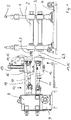
- FIGS. 1 and 2 show in a schematic cross section and in an isometric view the same part of an inventively designed profiling machine. It is a forming station, consisting of a framework 1 and an upper working shaft 2 and a lower working shaft 3, which are mounted in the frame 1.
- the working shafts 2, 3 are used to hold Rollumformwerkmaschineen (not shown).
- the framework 1 is fixedly attached to a machine frame 4. By means of a height adjustment 5, the working shafts 2, 3 can be moved vertically in the frame 1 in order to equip them in particular with different Rollumformmaschinemaschineen.
- the front side of the working shafts 2, 3 are provided with laterally out of the frame 1 leading out coupling counterparts 6, which are presently designed as a coupling pin 7 with splined.
- a gear block 8 of a drive system 9 is arranged.
- On this gear block 8 sit an upper propeller shaft 10 and a lower propeller shaft 11 to transmit torque from the drive system 9 and the transmission block 8 on the upper and lower working shafts 2, 3.
- the propeller shafts 10, 11 are telescopically variable in length and, of course, independently of their length and angular position transmit torque from a drive side 12 to an output side 13.
- On the output side 13, the propeller shafts 10, 11 are each provided with a coupling element 14, which is designed here as a coupling sleeve 15.
- the coupling elements 14 of the propeller shafts 10, 11 are each attached to a vertical slide 16, which in turn sits on a horizontal slide 17 (here concealed, in FIG. 3 dahen).
- the horizontal slide 17 is mounted on a bracket 18, which in turn is releasably secured to the drive system 9 and the transmission block 8.
- the vertical slide 16 is movable up and down by means of a vertical drive 19, while the horizontal slide 17 is moved by means of a horizontal drive 20 (FIG. FIG. 3 ) axially, that is to the working shafts 2, 3 and away from them is movable.
- Both drives, the vertical drive 19 and the horizontal drive 20, are pneumatic piston-cylinder units. They ensure that the coupling elements 14 on the output side 13 of the propeller shafts 10, 11 both axially and vertically, that is orthogonal to the axial direction, can be moved.
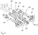
- FIG. 3 which are part of the FIGS. 1 and 2 As shown, the movement device for the vertical and the axial movement can be better recognized.
- the vertical slide 16 is seated, vertically movable, on a horizontal slide 17, which is held by a horizontal drive 20, also a pneumatic piston-cylinder unit, in the vertical or axial direction relative to the holder on which it is mounted, movable.
- the drive side 12 of the propeller shaft 10 is (not visible in this figure) fixed to the gear block 8 and connected via this stationary with the bracket 18, while the output side 13 of the propeller shaft 10 together with the coupling element 14 and the centering element 21 both horizontally and axially can also be moved vertically relative to the bracket 18.
- the coupling element 14 can be coupled to the coupling counterpart 6 of the (not shown here) upper working shaft 2 and decoupled from this. This is independently possible for each propeller shaft 10, 10 ', 11.
- the bracket 18 can be easily attached to the transmission block 8 or removed from it. By removing the holder 18 and the movement devices as well the propeller shafts 10, 10 'eliminated so that corresponding space between the frame 1 and the gear unit 8 is free.
- FIGS. 1 and 2 represent a situation before a coupling operation.
- the horizontal drive 20 of the lower propeller shaft 11 is activated, so that the coupling element 14 moves axially to the coupling counterpart 6 on the lower working shaft 3 by the horizontal slide 17, the output side 13 of the propeller shaft 11 moves horizontally.
- Trained as a coupling pin 7 coupling counterpart 6 on the lower working shaft 3 engages by this axial movement in the form of a coupling sleeve coupling element 14 and in this case forms a form fit with respect to a rotational movement.
- the Ankuppelvorgang the lower working shaft 3 is thus completed.
- an axial movement or horizontal movement of the driven side 13 of the upper propeller shaft 10 is not sufficient. Rather, the coupling element 14 must be moved vertically downward on the output side 13 of the upper propeller shaft 10 in order to bring the coupling sleeve 15 with the coupling pin 7 of the upper working shaft 2 in engagement.
- the horizontal drive 20 of the horizontal carriage 17 is a pneumatic drive, and the output side 13 of the propeller shaft 10 is provided with the centering element 21, a prior vertical alignment of the propeller shaft 10 to the working shaft 2 is unnecessary. Rather, the axial or horizontal movement of the horizontal carriage 20th for a normal hitching operation. In this case, then meets the sliding surface 22 of the centering 21 on the front side on the coupling pin 7. Due to the elastic spring properties of the pneumatic horizontal drive 20, the driven side 13 of the propeller shaft 10 does not move horizontally, but is elastically biased only in the axial direction.
- the sliding surface 22 of the centering element 21 is in this case sized so that, regardless of the current possible positions of the working shaft 2 and the coupling element 14, always the centering 21 meets the coupling pin 7, as far as the coupling sleeve 15 and the coupling pin 7 from the outset in Escape are arranged. This allows fully automatic coupling, without having to pay attention to the vertical positions of the propeller shafts 10, 11 and the working shafts 2, 3.
- the driven side 13 of the lower hinge shaft 11 is also provided with a centering element 21 with sliding surface 22, which is adapted to the maximum vertical movement path of the lower working shaft 3.
Landscapes
- Engineering & Computer Science (AREA)
- Mechanical Engineering (AREA)
- Agricultural Machines (AREA)
Priority Applications (1)
| Application Number | Priority Date | Filing Date | Title |
|---|---|---|---|
| EP16195127.2A EP3311932A1 (fr) | 2016-10-21 | 2016-10-21 | Profiliermaschine und kuppelvorrichtung für eine solche sowie ankuppelverfahren |
Applications Claiming Priority (1)
| Application Number | Priority Date | Filing Date | Title |
|---|---|---|---|
| EP16195127.2A EP3311932A1 (fr) | 2016-10-21 | 2016-10-21 | Profiliermaschine und kuppelvorrichtung für eine solche sowie ankuppelverfahren |
Publications (1)
| Publication Number | Publication Date |
|---|---|
| EP3311932A1 true EP3311932A1 (fr) | 2018-04-25 |
Family
ID=57206044
Family Applications (1)
| Application Number | Title | Priority Date | Filing Date |
|---|---|---|---|
| EP16195127.2A Pending EP3311932A1 (fr) | 2016-10-21 | 2016-10-21 | Profiliermaschine und kuppelvorrichtung für eine solche sowie ankuppelverfahren |
Country Status (1)
| Country | Link |
|---|---|
| EP (1) | EP3311932A1 (fr) |
Cited By (2)
| Publication number | Priority date | Publication date | Assignee | Title |
|---|---|---|---|---|
| CN110732574A (zh) * | 2019-10-23 | 2020-01-31 | 安徽跨宇钢结构网架工程有限公司 | 一种钢片弯曲机 |
| DE102022120537B3 (de) | 2022-08-15 | 2023-11-30 | PROFILMETALL-Engineering GmbH | Kuppelvorrichtung und Rollformanlage |
Citations (5)
| Publication number | Priority date | Publication date | Assignee | Title |
|---|---|---|---|---|
| EP0365976B1 (fr) | 1988-10-25 | 1993-07-21 | Gerhard Dipl.-Ing. Krückels | Machine de profilage |
| WO1995009060A1 (fr) * | 1993-09-27 | 1995-04-06 | Nakata Manufacturing Co., Ltd | Dispositif d'accouplement d'arbre pour laminoir a profiler les feuillards a froid |
| EP2251110A1 (fr) * | 2009-05-13 | 2010-11-17 | DREISTERN GmbH & Co.KG | Machine à profiler |
| EP2452760B1 (fr) | 2010-11-16 | 2013-02-20 | DREISTERN GmbH & Co.KG | Machine à profiler et supports d'accouplement pour une telle machine |
| WO2015085340A2 (fr) * | 2013-12-10 | 2015-06-18 | Asmag-Holding Gmbh | Système d'entraînement et installation de profilage équipée de celui-ci |
-
2016
- 2016-10-21 EP EP16195127.2A patent/EP3311932A1/fr active Pending
Patent Citations (5)
| Publication number | Priority date | Publication date | Assignee | Title |
|---|---|---|---|---|
| EP0365976B1 (fr) | 1988-10-25 | 1993-07-21 | Gerhard Dipl.-Ing. Krückels | Machine de profilage |
| WO1995009060A1 (fr) * | 1993-09-27 | 1995-04-06 | Nakata Manufacturing Co., Ltd | Dispositif d'accouplement d'arbre pour laminoir a profiler les feuillards a froid |
| EP2251110A1 (fr) * | 2009-05-13 | 2010-11-17 | DREISTERN GmbH & Co.KG | Machine à profiler |
| EP2452760B1 (fr) | 2010-11-16 | 2013-02-20 | DREISTERN GmbH & Co.KG | Machine à profiler et supports d'accouplement pour une telle machine |
| WO2015085340A2 (fr) * | 2013-12-10 | 2015-06-18 | Asmag-Holding Gmbh | Système d'entraînement et installation de profilage équipée de celui-ci |
Cited By (3)
| Publication number | Priority date | Publication date | Assignee | Title |
|---|---|---|---|---|
| CN110732574A (zh) * | 2019-10-23 | 2020-01-31 | 安徽跨宇钢结构网架工程有限公司 | 一种钢片弯曲机 |
| DE102022120537B3 (de) | 2022-08-15 | 2023-11-30 | PROFILMETALL-Engineering GmbH | Kuppelvorrichtung und Rollformanlage |
| EP4324573A1 (fr) | 2022-08-15 | 2024-02-21 | PROFILMETALL Engineering GmbH | Dispositif d'accouplement et installation de profilage à rouleaux |
Similar Documents
| Publication | Publication Date | Title |
|---|---|---|
| AT504640B1 (de) | Biegemaschine | |
| EP3409391B1 (fr) | Unité d'outil pour une machine d'extrusion destiné à la fabrication en continu d'un profilé d'une matière à extruder déformable | |
| EP3268144B1 (fr) | Machine à dresser et procédé de remplacement d'éléments de roulement à dresser | |
| EP2701860B1 (fr) | Monture d'outil pour presse plieuse | |
| AT515177B1 (de) | Antriebssystem sowie damit ausgerüstete Profilieranlage | |
| EP0685276B1 (fr) | Dispositif de transfert dans une machine de formage, en particulier dans une presse de transfert | |
| EP3311932A1 (fr) | Profiliermaschine und kuppelvorrichtung für eine solche sowie ankuppelverfahren | |
| EP0323607B1 (fr) | Machine à forger en long pour forger des barres circulaires ou des barres à angles vifs | |
| EP0365976B1 (fr) | Machine de profilage | |
| EP2452760B1 (fr) | Machine à profiler et supports d'accouplement pour une telle machine | |
| DE967373C (de) | Vertikalwalzengeruest | |
| AT411021B (de) | Walzstrasse zum walzen von metallischen rohren, stäben oder drähten | |
| EP1914020B1 (fr) | Dispositif de profilage pour une machine de profilage par laminage | |
| DE3312396C2 (de) | Vorrichtung zum Zentrieren eines Bewehrungskorbs | |
| EP0568854A2 (fr) | Procédé et accouplement rapide pour la connection d'un tracteur à un outil agricole | |
| EP2251110A1 (fr) | Machine à profiler | |
| WO2006045284A1 (fr) | Dispositif de changement d'outillage automatique | |
| EP2251112B1 (fr) | Machine à profiler et procédé de formage longitudinal d'une bande de métal ou d'un profil de départ dans un profil ou un tuyau | |
| DE102022120537B3 (de) | Kuppelvorrichtung und Rollformanlage | |
| DE60022731T2 (de) | Blechbiegevorrichtung | |
| DE102005012297B4 (de) | Schmiedemaschine | |
| WO2017190855A1 (fr) | Dispositif de production d'armatures | |
| EP2179804A1 (fr) | Machine de profilage et procédé de mesure des rouleaux d'une machine à profiler | |
| WO2023116967A1 (fr) | Système de transfert à trois axes d'une presse de transfert | |
| EP0940198B1 (fr) | Appareil de cintrage |
Legal Events
| Date | Code | Title | Description |
|---|---|---|---|
| PUAI | Public reference made under article 153(3) epc to a published international application that has entered the european phase |
Free format text: ORIGINAL CODE: 0009012 |
|
| STAA | Information on the status of an ep patent application or granted ep patent |
Free format text: STATUS: THE APPLICATION HAS BEEN PUBLISHED |
|
| AK | Designated contracting states |
Kind code of ref document: A1 Designated state(s): AL AT BE BG CH CY CZ DE DK EE ES FI FR GB GR HR HU IE IS IT LI LT LU LV MC MK MT NL NO PL PT RO RS SE SI SK SM TR |
|
| AX | Request for extension of the european patent |
Extension state: BA ME |
|
| STAA | Information on the status of an ep patent application or granted ep patent |
Free format text: STATUS: REQUEST FOR EXAMINATION WAS MADE |
|
| 17P | Request for examination filed |
Effective date: 20180503 |
|
| RBV | Designated contracting states (corrected) |
Designated state(s): AL AT BE BG CH CY CZ DE DK EE ES FI FR GB GR HR HU IE IS IT LI LT LU LV MC MK MT NL NO PL PT RO RS SE SI SK SM TR |
|
| STAA | Information on the status of an ep patent application or granted ep patent |
Free format text: STATUS: EXAMINATION IS IN PROGRESS |
|
| 17Q | First examination report despatched |
Effective date: 20210507 |
|
| STAA | Information on the status of an ep patent application or granted ep patent |
Free format text: STATUS: EXAMINATION IS IN PROGRESS |
|
| GRAP | Despatch of communication of intention to grant a patent |
Free format text: ORIGINAL CODE: EPIDOSNIGR1 |
|
| STAA | Information on the status of an ep patent application or granted ep patent |
Free format text: STATUS: GRANT OF PATENT IS INTENDED |
|
| INTG | Intention to grant announced |
Effective date: 20240410 |