EP2451591B1 - Vorrichtung und verfahren zur inspektion nach dem dreschen und zur sortierung von tabakschichten - Google Patents
Vorrichtung und verfahren zur inspektion nach dem dreschen und zur sortierung von tabakschichten Download PDFInfo
- Publication number
- EP2451591B1 EP2451591B1 EP10817573.8A EP10817573A EP2451591B1 EP 2451591 B1 EP2451591 B1 EP 2451591B1 EP 10817573 A EP10817573 A EP 10817573A EP 2451591 B1 EP2451591 B1 EP 2451591B1
- Authority
- EP
- European Patent Office
- Prior art keywords
- contaminants
- tobacco lamina
- separation conduit
- station
- air
- Prior art date
- Legal status (The legal status is an assumption and is not a legal conclusion. Google has not performed a legal analysis and makes no representation as to the accuracy of the status listed.)
- Not-in-force
Links
- 241000208125 Nicotiana Species 0.000 title claims description 178
- 235000002637 Nicotiana tabacum Nutrition 0.000 title claims description 178
- 238000007689 inspection Methods 0.000 title claims description 100
- 238000000034 method Methods 0.000 title claims description 35
- 238000000926 separation method Methods 0.000 claims description 127
- 239000000356 contaminant Substances 0.000 claims description 118
- 230000002950 deficient Effects 0.000 claims description 24
- 230000005484 gravity Effects 0.000 claims description 13
- 238000011144 upstream manufacturing Methods 0.000 claims description 9
- 239000012530 fluid Substances 0.000 claims description 8
- 238000005286 illumination Methods 0.000 claims description 8
- 230000008878 coupling Effects 0.000 claims description 7
- 238000010168 coupling process Methods 0.000 claims description 7
- 238000005859 coupling reaction Methods 0.000 claims description 7
- 238000000151 deposition Methods 0.000 claims description 5
- 230000003213 activating effect Effects 0.000 claims description 2
- 238000004062 sedimentation Methods 0.000 claims description 2
- 230000003287 optical effect Effects 0.000 description 16
- 206010070245 Foreign body Diseases 0.000 description 6
- 238000011109 contamination Methods 0.000 description 6
- 238000003491 array Methods 0.000 description 5
- 238000001514 detection method Methods 0.000 description 4
- 230000032258 transport Effects 0.000 description 4
- 230000000694 effects Effects 0.000 description 3
- 239000000463 material Substances 0.000 description 3
- 238000002347 injection Methods 0.000 description 2
- 239000007924 injection Substances 0.000 description 2
- 230000003466 anti-cipated effect Effects 0.000 description 1
- 238000004891 communication Methods 0.000 description 1
- 230000007547 defect Effects 0.000 description 1
- 238000005516 engineering process Methods 0.000 description 1
- 239000012634 fragment Substances 0.000 description 1
- 238000003384 imaging method Methods 0.000 description 1
- 238000012634 optical imaging Methods 0.000 description 1
- 239000002245 particle Substances 0.000 description 1
- 238000010926 purge Methods 0.000 description 1
- 230000003068 static effect Effects 0.000 description 1
- 235000019505 tobacco product Nutrition 0.000 description 1
- 210000003462 vein Anatomy 0.000 description 1
Images







Classifications
-
- H—ELECTRICITY
- H04—ELECTRIC COMMUNICATION TECHNIQUE
- H04N—PICTORIAL COMMUNICATION, e.g. TELEVISION
- H04N7/00—Television systems
- H04N7/18—Closed-circuit television [CCTV] systems, i.e. systems in which the video signal is not broadcast
- H04N7/188—Capturing isolated or intermittent images triggered by the occurrence of a predetermined event, e.g. an object reaching a predetermined position
-
- A—HUMAN NECESSITIES
- A24—TOBACCO; CIGARS; CIGARETTES; SIMULATED SMOKING DEVICES; SMOKERS' REQUISITES
- A24C—MACHINES FOR MAKING CIGARS OR CIGARETTES
- A24C5/00—Making cigarettes; Making tipping materials for, or attaching filters or mouthpieces to, cigars or cigarettes
- A24C5/39—Tobacco feeding devices
- A24C5/396—Tobacco feeding devices with separating means, e.g. winnowing, removing impurities
Definitions
- the present invention relates to an apparatus and method for post-threshing inspection and sorting of tobacco lamina, and more specifically to a device and methodology which is useful for optically inspecting an air stream containing acceptable tobacco lamina which has been produced from a threshing operation, and further identifying and then removing contaminants from the air stream which is carrying the tobacco lamina.
- EP 1 591 172 A1 describes a method and an apparatus for the separation of foreign bodies from a tobacco stream.
- a portion of the material from the tobacco stream is conveyed into the area of a foreign-body detection device in the form of a partial tobacco stream, whereby foreign bodies are identified by the foreign-body detection device in the partial tobacco stream and subsequently removed from the partial tobacco stream, whereby the partial tobacco stream is formed by a separation step by an air flow upstream from the foreign-body detection device.
- a first aspect of the present invention relates to an apparatus according to claim 1, namely an apparatus for the post-threshing inspection and sorting of tobacco lamina, comprising:
- a further aspect of the present invention relates to a method according to claim 9, namely a method for the post-threshing inspection and sorting of tobacco lamina, comprising: providing a substantially vertically oriented separation conduit defined by an internal sidewall and which has a proximal and a distal end, and an intermediate portion, and wherein the internal sidewall of the substantially vertically oriented separation conduit further defines an internal passageway extending between the proximal and distal ends; providing a substantially moveable wall within the internal passageway of the separation conduit, and wherein the moveable wall has opposite sides; delivering a source of a tobacco lamina, and other contaminants each having given weights, and which have been produced from a threshing operation, into the internal passageway at a location which is between the proximal and distal ends of the substantially vertically oriented separation conduit; delivering a first air stream having a given air pressure, volume, and speed into the proximal end of the vertically oriented separation conduit and which is sufficient to carry away tobacco lamina and
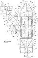
- the present invention is best understood by a study of Fig. 1 .
- the invention is employed for the post-threshing inspection and sorting of tobacco lamina.
- the apparatus which is generally indicated by the numeral 10
- a threshing operation which is generally indicated by the numeral 11.
- a threshing operation generally receives a source of whole tobacco leaves and thereafter physically manipulates or treats them in a manner so as to fragment the tobacco leaves into individual parts or small pieces.
- the threshing operation 11 produces a source of post-threshed tobacco lamina and other contaminants which are generally indicated by the numeral 12, and which is deposited on a first conveyor which is indicated by the numeral 13.
- the first conveyor has an upwardly facing supporting surface 14, and is operable to transport the source of post-threshed tobacco lamina and other contaminants 12 from the intake end 15 thereof, to the discharge or exhaust end 16 where the source of post-threshed tobacco lamina, and other contaminants 12, is deposited, by means of gravity, within an air lock which will be described in greater detail, below.
- air lock which will be described in greater detail, below.
- other means for transporting the tobacco lamina to the air lock could be employed with equal success.
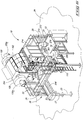
- the apparatus of the present invention 10 generally includes a support frame 20 which locates the apparatus in a generally vertical orientation.
- the support frame 20 comprises a multiplicity of generally vertically oriented frame members 21 which are interconnected together by a plurality of horizontally oriented bracing or other frame members 22.
- the support frame has a bottom end or portion 23 which is affixed on, or otherwise attached to, a supporting surface such as the surface of the earth, or a factory floor, or the like.
- the same support frame 20 has a top portion or upper end 25.
- the apparatus 20 is generally supported on, or otherwise affixed to given locations along the support frame 20.
- the apparatus 10 includes an in-feed air lock which is generally indicated by the numeral 30.
- This in-feed air lock joins or otherwise operably couples together an adjacent separation conduit, which will be discussed in greater detail hereinafter, and the first conveyor 13 for carrying and depositing the source of tobacco lamina and other contaminants 12.
- the in-feed air lock 30 is defined by a housing 31 which is fastened on the earlier described vertically oriented frame members 21 at a location somewhere between the bottom portion 23, and the top portion 25 of the support frame 20.
- the in-feed air lock 30 is of substantially conventional design.
- the housing 31 has an outside wall 32, and an opposite inside wall 33, which defines a passageway 34 which extends between an intake aperture 35, and an exhaust aperture 36.
- a rotatable feeding or intake wheel 40 As seen in Fig. 2 , and located intermediate the intake aperture 35, and the exhaust aperture 36 is a rotatable feeding or intake wheel 40.
- the rotatable feeding or intake wheel includes a plurality of spaced, radially extending paddles or arms 41.
- a plurality of cavities 42 are defined between the respective radially extending paddles or arms 41, and are individually operable to receive the source of post-threshed tobacco lamina and other contaminants 12 which are delivered by the first conveyor 13, and deposited by gravity into the intake aperture 35 from the discharge or exhaust end 16 of the first conveyor 13.
- the rotatable feeding or intake wheel 40 is rotated in a given direction by means of a motor 43 ( Fig. 1 ) which is mounted on the housing 31.
- the motor 43 is selectively energized so as to rotate the rotatable feeding wheel 40 in a given direction which is effective to deposit the source of post-threshing tobacco lamina and other contaminants 12 into a sliding chute which will discussed in the paragraphs which follow.
- the in-feed air lock 30 and more specifically the exhaust aperture 36 thereof is coupled in feeding relation relative to a sliding or delivery chute which is generally indicated by the numeral 50.
- the sliding or delivery chute 50 is oriented in an angulated relationship relative to the in-feed air lock 30, and further has a first end 51 which is affixed to the outside wall 32 of the housing 31, and an opposite, second or exhaust end 52. Still further, the sliding or delivery chute 50 has an outside facing surface 53 ( Fig. 3 ), and an opposite, inside facing surface 54, which defines an internal passageway 55 extending between the first end 51, and the opposite, second end 52.
- the internal passageway 55 receives the source of post-threshed tobacco lamina, and other contaminants 12, and which have been previously delivered to the in-feed air lock 30 by means of the first conveyor 13.
- the sliding or delivery chute 50 has a top or front facing sidewall 60; and a back, or rear facing sidewall 61. Still further, the back sidewall 61 is located adjacent to a bottom sidewall 62. However, as seen in Fig. 3 , it will be noted that the back sidewall 61 is spaced from the bottom sidewall 62. This spatial relationship defines a slit, gap or space 63, therebetween.
- This gap, slit or space 63 defines an aperture 64 which is coupled to an adjacent air passageway which is generally indicated by the numeral 65.
- the air passageway 65 is mounted in fluid flowing relation relative to an air manifold that is indicated by the numeral 70, and which is mounted adjacent to the bottom sidewall 62.
- the air manifold 70 defines a multiplicity of air exhaust ports 71.
- a fan 80 of conventional design ( Figs. 1 and 9 ) is coupled to the air manifold 70, and supplies an air stream 81 which enters the air manifold 70 and thereafter escapes through the air exhaust ports 71.
- the air stream 81 travels along the air passageway 65, and through the gap, slit or space 63 and into the internal passageway 55 of the sliding or delivery chute 50.
- This air stream 81 is operable to engage the source of post-threshed tobacco lamina and other contaminants 12 which has been delivered to the sliding delivery chute 50 and which previously traveled to the second end 52 of the sliding delivery chute 50 under the influence of gravity.
- the air stream 81 prevents the sedimentation or collection of the tobacco lamina or other contaminants on the bottom sidewall 62, and causes the tobacco lamina and other contaminants 12 to generally move or be blown along a parabolic path of travel ( Fig. 2 ), which is generally indicated by the numeral 82, out of the second end 52 of the sliding or delivery chute 50, and into the separation conduit which will be described, hereinafter. This is seen most clearly by reference to Fig. 2 .
- the sliding or delivery chute 50 further includes an adjustable or slideable door 90 which is mounted near the second end 52 of the sliding or delivery chute 50.
- the adjustable sliding door is operable to be placed in selectively occluding relation relative to the slit, gap or space 63 which is defined between the back sidewall 61, and the bottom sidewall 62 thereof.
- the adjustable slideable door is moveable between a first position 91, and a second position 92. In the second position 92 the adjustable/slideable door 90 substantially occludes the aforementioned slit, gap or space 63.
- posts 93 are provided, and mounted on the adjustable/slideable door 90. These posts 93 allow an operator to selectively move the adjustable/slideable door to given positions between the first and second positions 91 and 92 so as to control the amount of the air stream 81 which is supplied into the internal passageway 55, and which creates the parabolic path of travel 82 for the tobacco lamina and other contaminants 12 which has been previously received at the second end 52 of the sliding or delivery chute 50.
- the apparatus 10 of the present invention further includes a separation conduit 100 which is mounted in a fixed location relative to the surface of the earth 24 by means of the support frame 20.
- the separation conduit 100 has a proximal or first end 101; a second or distal end 102 ( Figs. 5 and 6 ); and an intermediate portion 103 ( Fig. 1 ) located between the proximal and distal ends 101 and 102.
- the separation conduit 100 is defined by a multiplicity of sidewalls 104 each having an inside facing surface 104A ( Fig. 2 ).
- the inside facing surfaces of the multiplicity of sidewalls 104 define an internal cavity 105 which has a variable cross-sectional dimension when measured between the proximal and distal ends 101 and 102 thereof.
- the separation conduit 100 extends generally vertically upwardly, and is held in that location by the support frame 20.
- an aperture 106 is formed in one of the sidewalls 104, and thereby allows the internal cavity 105 to communicate or be coupled with the second end 52, of the sliding or delivery chute 50. Through the aperture 106, the tobacco lamina or other contaminants 12 move along the parabolic path of travel 82 as seen in that drawing.
- a transparent window 107 is removably mounted on the separation conduit 100, and is located between the proximal or first end 101, and the intermediate portion 103. This window allows an operator to view into the internal cavity 105, and thereafter make adjustments to the operation of the apparatus 10 as will be discussed in greater detail, hereinafter.
- a removable contamination collection container or assembly 110 is mounted near the proximal or first end 101 of the separation conduit 100 and is operable to collect heavier contaminants which move in the direction of the proximal end 101 of the separation conduit 100, under the influence of gravity, and against the direction of an air stream which is delivered into the separation conduit.
- the contaminants which move under the influence of gravity typically have a weight of greater than about 0.8 grams/cm 2 . These heavier contaminants are then periodically removed from the separation conduit 100 by an operator. Additionally, it will be seen in Fig.
- an air stream delivery device 120 is positioned in air stream delivering relation relative to the proximal end 101 of the separation conveyor 100 and which, when energized, delivers an air stream 121 ( Figs. 1 and 2 ) having a given pressure and speed, to the proximal end 101 of the separation conveyor 100.
- the air stream 121 is operable to carry the tobacco lamina, and some lighter weight contaminants 12 in the direction of the distal end 102 of the separation conduit 100. As discussed above, some heavier contaminants move in the opposite direction and forward the proximal end 101 of the separation conduit 100, and are thereby received in the removable collection container 110. Additionally, it will be seen from a study of Figs.
- a suction device which is generally indicated by the numeral 130, and which is depicted herein as a conventional fan, is positioned in air stream 121 removing relation relative to the distal end 102 of the separation conduit 100.
- the suction device 130 when energized, removes a given volume of the air stream 121 which is delivered by the air stream delivery device 120, and which is carrying the tobacco lamina generally vertically from the proximal end 101 to the distal end 102.
- the respective air stream delivery device 120, and suction device 130 are each energized by motors 120A and 130B, respectively, to effect the aforementioned delivery and removal of the air stream 121 from the separation conduit 100.
- the velocity of the air stream 121 is about 3 to about 8 meters/second. Still further, it will be understood from the arrangement as seen in the drawings, that the intermediate portion 103 of the separation conduit 100 increases the air stream 121 velocity as the air stream 121 moves in a direction from the proximal end 101, to the distal end 102 of the separation conduit 100.
- the individual post-threshed tobacco lamina and other contaminants 12 carried by the air stream 102 each have a weight of typically less than about 0.8 grams/cm 2 .
- the contaminants which move in the direction of the proximal end 101 of the separation conduit 100 move under the influence of gravity, and against the direction of the air stream 121.
- an in-feed air lock 30 is provided, and which is joined to the separation conduit 100, and located in receiving relation relative to the conveyor 13, and which is further operable for carrying and depositing the source of tobacco lamina and other contaminants 12 within the separator conduit 100.
- a sliding or delivery chute 50 is provided, and which couples the in-feed air lock 30 and separation conduit 100 together. In the arrangement as earlier described, the tobacco lamina and other contaminants 12 provided by the conveyor 13 are delivered by the in-feed air lock 30 into the delivery chute 50.
- an air stream or source of pressurized air 81 is supplied to the sliding or delivery chute 50, and which is effective to propel the tobacco lamina and other contaminants 12 out of the sliding or delivery chute 50 and along a trajectory or parabolic path of travel 82 into the separation conduit 100 as depicted in Fig. 2 .
- the heaviest contaminants (described above) move under the influence of gravity and in the direction of the proximal end 101, and are then collected in the container 110.
- the apparatus 10 includes a selectively moveable wall 140 which is mounted within the internal cavity 105 of the separation conduit 100.
- This selectively moveable wall 140 is located between the proximal end 101, and the intermediate portion 103, and which further, when selectively moved, adjusts the speed of the air stream 121 which is supplied by the air stream delivery device 120.
- the selectively moveable wall 140 has a first hingedly mounted end 141, and an opposite, second, hingedly mounted end 142.
- the selectively moveable wall includes first, second, third and fourth portions 143, 144, 145 and 146, respectively. As seen in the drawings, the respective portions are serially, hingedly, mounted together.
- the selectively moveable wall 140 is oriented in an appropriate, predetermined location relative to the internal cavity 105 of the separation conduit 100, by means of several threaded adjustment rods 150.
- a first and a second rod 151 and 152 which are depicted, and which are individually affixed to the third portion 145.
- These respective rods are threadably engaged by individual threaded fasteners 153 which allow the respective rods to be selectively threadably advanced or withdrawn relative to various locations within the internal cavity 105.
- the selectively moveable wall 140 moves under the influence of the respective rods 151 and 152 along a path of travel 154.
- An operator by adjusting the length that the respective rods 150 extend into the cavity 105, may effect a change in the speed of the air stream 121 moving through the internal cavity 105 by either making the internal cavity smaller or larger.
- the air speed 121 is made effective and optimal for carrying the tobacco lamina 12 to be sorted to a downstream inspection station which will be discussed in greater detail, hereinafter, and further avoids the use of costly motor speed control arrangements for use on the motors 120A and 130A. respectively.
- the present separation conduit 100 includes a venturi section 160 which is located generally at the intermediate portion 103 thereof.
- the venturi section 160 has a first end 161 having a first cross-sectional dimension, and a second end 162, which is spaced from the first end 161, and which has a second cross-sectional dimension which is less than the first cross-sectional dimension.
- the effect of the venturi section 160 is to increase the speed of the air stream 120 carrying the tobacco lamina and the light weight contaminants 12 that are to be inspected.
- the guide portion 170 of the separation conduit 100 positioned downstream relative to the venturi section 160, and upstream of the inspection station which will be discussed, is the guide portion 170 of the separation conduit 100. More specifically, the guide portion 170 comprises first and second sidewall surfaces 171 and 172 which are located in spaced relation one relative to the other, ( Fig. 1 ); and third and fourth sidewall surfaces 173 and 174 ( Fig. 4 ), which are located in predetermined spaced relation one relative to the other, and which individually join the first and second sidewall surfaces 171 and 172 together so as to form a portion of the internal cavity 105.
- the guide portion 170 is substantially rectangular in shape ( Fig. 4 ).
- first guide plate 175 is mounted in the internal cavity 105, and on the third sidewall 173 and between the first and second sidewall surfaces 171 and 172, respectively; and a second guide plate 176 is mounted in the internal cavity 105, and on the fourth sidewall 174 between the first and second sidewall surfaces 171 and 172, respectively.
- a first space 177 is defined between the first guide plate 175, and the third sidewall 173; and a second space 178 is defined between the second guide plate 176, and the fourth sidewall 174.
- first and second air injection ports 181 and 182 are formed in the third and fourth sidewalls 173 and 174, respectively, and a source of compressed air 183 ( Fig. 8 ) previously generated by the fan 80, is delivered by means of the conduit 184 to each of the air injection ports 182.
- the source of compressed air 183 forms an air stream 185 ( Fig. 4 ) which is delivered to and moves along within the first and second spaces 177 and 178 as indicated by the arrows in that drawing.
- the air stream 185 provides a means by which the product to be inspected, that being, the tobacco lamina and any remaining contaminants 12 are centered substantially centrally relative to the internal cavity 105.
- This centering of the product to be inspected permits a complete viewing of the product when it arrives within the inspection station which is located downstream relative to the guide portion 170, and substantially prevents any defects from becoming oriented in "blind corners" where it cannot be imaged by the camera which will be described in greater detail, below.
- the speed of the air stream 121 which is transporting the tobacco lamina and other contaminants 12 at this point in the separation conduit 100 is adjustable from approximately 20-22 meters per second.
- an inspection station which is generally indicated by the numeral 200 is located downstream of the intermediate portion 103 of the separation conduit 100, and upstream of the distal end 102 thereof.
- the inspection station 200 is rendered operable to optically inspect the air stream 121 carrying the tobacco lamina and the light weight contamination 12 passing through the inspection station 200.
- the inspection station identifies both defective or unacceptable tobacco lamina, and any remaining light weight contamination in the air stream 121, and further produces a suitable electrical sorting signal which is appropriate for what has been optically inspected.
- the inspection station 200 is formed of optically transparent first; second; third; and fourth sidewalls which are generally indicated by the numerals 201; 202; 203; and 204, respectively.
- a slit or opening 205 is formed in the fourth sidewall 204, and which permits an optical viewing assembly, such as a camera, to view or optically image therethrough.
- an optical viewing assembly such as a camera
- a backlight assembly 206 is shown mounted in a location adjacent to the inspection station 200 and which is operable to generate visible light which passes through the transparent third side wall 203 to illuminate the tobacco lamina, and other contamination 12 which is passing through the inspection station 200.
- This backlight assembly is pivotally moveable away from the inspection station 200 ( Fig. 9 ). This pivotal movement permits an operator to gain access to the inspection station 200 so as to remove, and periodically clean or maintain the inspection station so as to ensure proper imaging of the product which is passing therethrough.
- the transparent walls 201, 202 ( Fig. 9 ), 203 and 204 which forms this portion of the inspection station 200 is generally trapezoidal in shape when viewed, for example, in Fig. 5 . This shape allows for the convenient removal of this portion of the inspection station portion 200 so that it may be conveniently serviced and cleaned periodically by the operator of the apparatus 10.
- an illumination source 210 which, when energized, emits visible light which passes through the optically transmissive inspection station 200, or portion of the separation conduit 100 so as to illuminate the source of tobacco lamina and other contaminants 12 passing therethrough.
- the illumination source 210 includes a first bank of high intensity discharge lamps 211; and a second bank of similar, high intensity discharge lamps 212.
- the specific illumination sources 211 and 212 are angled relative to the inspection station 200.
- a gap or slit 213 is defined between the first and second banks of lamps 211 and 212, respectively.
- the gap or slit 213 permits light reflected from the tobacco lamina or other contaminants passing through the inspection station 200 to be reflected back through the substantially coaxially aligned openings 205 which is formed in the side wall 204, and the slit 213, so that the reflected light may be optically imaged by an optical viewing assembly which will be discussed, hereinafter.
- the optical and electrical equipment housing 214 defines an internal cavity 215 which mounts a suitable camera 220 at a given location within the internal cavity 215, and which has a focal length in the present form of the invention of about 105 mm.
- Mounted within the internal cavity 215 is also a mirror 221 which is operable to receive the reflected light coming from the inspection station 200, and which has passed previously through the gap or slit 213 formed between the first and second banks of lamps 211 and 212.
- This mirror 221 reflects this same light, which has been reflected from the tobacco lamina and other contaminants 12 passing through the inspection station 200, and in the direction of the camera 220 where it may be received, imaged, and produce a suitable electrical image signal.
- This reflected light beam passes through the region 222 as shown in Fig. 12 .
- a suitable computer 223 mounted within the internal cavity 215 of this optical and electrical equipment housing 214 is a suitable computer 223 which is coupled in electrical image signal receiving relation relative to the camera 220. Once received, the computer is operable to send a suitable electrical sorting signal to a reject station which is mounted downstream relative to the inspection station 200, and which will be discussed in greater detail, hereinafter.
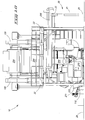
- a graphic user interface Electrically coupled to the computer 223 is a graphic user interface, or operator input device 224, and which is best seen by reference to Fig. 8 .
- This graphic user interface/operator input device allows an operator to adjust the operation of the inspection station 200, and other operational aspects of the apparatus 10.
- the camera 220 is operable to substantially image the entire source of tobacco lamina, and other contaminants 12 passing through the inspection station 200.
- the present arrangement substantially prevents tobacco lamina and other contamination 12 from hiding or otherwise passing into regions or areas of the internal cavity 105 where it may not be effectively optically imaged. Therefore, in the arrangement as seen in Fig.
- the present apparatus 10 provides a camera 220 which is focused on the illuminated tobacco lamina and other contaminants 12 passing through the optically transmissive inspection station or portion 200 of the separation conduit 100 so that defective or otherwise unacceptable tobacco lamina or other contaminants may be optically imaged by the camera, and then effectively identified as contaminants or as unwanted material that needs to be removed from the product stream, by the computer 223, in a manner well understood in the art.
- the apparatus 10 includes a tobacco lamina and/or contaminant reject station which is generally indicated by the numeral 230, and which further is located downstream of the previously described inspection station 200, and is additionally coupled in electrical sorting signal receiving relation relative thereto. More specifically, the computer 223 is coupled in controlling relation relative to the reject station 230. As seen in the drawings, the tobacco lamina reject station 230 is further located upstream of the suction device 130.
- the tobacco lamina reject station 230 is maintained at substantially ambient atmospheric pressure, and the air stream delivery device 120, and the intermediate portion 103 of the separation conduit 100 create an air speed and pressure within the separation conduit 100 which substantially maintains the speed of movement of the tobacco lamina and other contaminants 12 as they move between the inspection station 200, and the tobacco lamina reject station 230 which is located downstream relative thereto.
- the tobacco lamina reject station 230 upon receiving the electrical sorting signal generated by the computer 223 in the inspection station 200 is effective in removing any defective tobacco lamina, and other contaminants 12, from the air stream 121 which is delivered from the inspection station 200.
- the suction device 130 removes a volume of the air stream 121 carrying acceptable tobacco lamina from the tobacco lamina reject station 230 at a speed which is substantially equal to the speed at which the tobacco lamina and other contaminants 12 were delivered to the tobacco lamina reject station 230.
- the volume and velocity of the air stream 121, in the reject station 230 is about 20 meters/second to about 27 meters/second.
- the air stream 121 produces an air pressure within the internal cavity 105 of the separation conduit 100 between the proximal and distal ends 101 and 102 thereof.
- the air pressure as measured at the inspection station 200 is not greater than about 1 hPa, the air pressure as measured at the tobacco lamina reject station 230.
- the tobacco lamina reject station 230 is defined, at least in part, by first, second, third and fourth walls 231-234, respectively. As seen most clearly by reference to Fig. 5 , an opening 235 is formed in the fourth wall 234, and which communicates with the ambient environment. Still further, a smaller opening 236 is formed in the first wall 231. Referring still to Fig.
- the apparatus 10 includes a reject container 240 which is maintained at substantially ambient atmospheric pressure, and which is further defined by a plurality of foraminous sidewalls 241 which together, in combination, define an internal expansion chamber or cavity 242 for receiving rejected tobacco lamina, or other contaminants 12 which have been previously indentified, and then ejected from the tobacco lamina reject station 230 based upon the electrical sorting signal that has been received from the computer 223 which is located in the inspection station 200.
- the reject container 240 which is maintained at substantially ambient atmospheric pressure, includes a discharge opening 243 which allows rejected tobacco lamina or other contaminants 12 to move, under the influence of gravity, through the discharge opening 243, and be received in a discharge conduit 244.
- the discharge conduit transports the defective tobacco lamina, and any other contaminants 12, away from the reject container 240, and then supplies it to a second optical inspection device which will be discussed in greater detail, hereinafter ( Fig. 8 ).
- An aperture 246 is formed in the wall 234 near the location where the wall 234 joins the reject container 240. Further, the aperture 246 may be selectively occluded by a door or covering 247. By the selective occlusion of the aperture, an operator may substantially prevent a back pressure from developing which might be effective in removing or drawing in previously ejected contaminants back into the air stream 121 from the reject container 240, and which is maintained at substantially ambient pressure. As seen in Fig.
- another air manifold 248 is provided and which injects an air stream 248A into the conduit 244.
- This air stream 248A is used to purge defective tobacco lamina received in the container 240 and which otherwise may be caught in an air eddy which could cause them to become entrained in a return air flow which might transport them back toward the separator conduit 100.
- the air conduit is coupled in fluid flowing relation relative to an adjustable valve 248B.
- a low pressure air source 249 is provided to the valve 248A.
- the apparatus 10 includes a plurality of air ejector valves 250 here shown as a first air powered ejector valve array 251, and a second air powered ejector valve array 252.
- the ejector valve arrays are individually disposed in predetermined spaced relation, one relative to the other.
- the first and second air powered ejector valve arrays 251 and 252 have individual air ejector valves which are coupled to a source of pressurized air 253 which is best seen by reference to Fig. 7 and following.
- the respective air ejector valve arrays are positioned in ejecting fluid communication with the rejection container 240, and further communicate with the tobacco lamina reject station 230 by means of the opening 236 which is formed in the first wall 231.
- the first and second air powered ejector valve arrays 251 and 252 are responsive to the electrical sorting signal produced by the inspection station 200.
- the respective ejector valves 250 are rendered operational, they are effective to provide selected jets of air so as to remove predetermined individually defective tobacco lamina and other contaminants 12 from the air stream 121 which is traveling through the tobacco lamina reject station 200. These rejected tobacco lamina or other contaminants then move under the influence of these selective jets of air into the reject container 240.
- the reject container 240 has a static air pressure relative to the ambient atmospheric pressure of less than about 1 hPa.
- the acceptable tobacco lamina and other contaminants 12 traveling in the air stream 121 then moves from the reject station 230 along the separation conduit 100, and then enters an air/tobacco separator which is generally indicated by the numeral 254, and which is well understood in the art ( Fig. 7 ).
- the air tobacco separator is effective in removing the acceptable tobacco lamina, and then supply it, by gravity flow, to a conduit 255.
- the conduit 255 deposits the acceptable tobacco lamina 12, which has been sorted, onto an underlying take away conveyor 256 which is mounted on the support frame 20, and oriented in receiving relation relative to the conduit 255 for further processing.
- the air/tobacco separator 254 is coupled in fluid flowing relation relative to the air stream delivery device 120, and the suction device 130. These devices cooperate with the air/tobacco separator 254 so as to remove the acceptable tobacco lamina from the air stream 121.
- the present apparatus 10 includes a second optical inspection device which is generally indicated by the numeral 270.
- This second optical inspection device can be purchased commercially from Key Technology, Inc. of Walla Walla, Washington under the trademark "OPTYX 3000.”
- This second optical inspection device 270 is mounted in downstream receiving relation relative to the discharge conduit 244.
- the discharge conduit 244 transports away the rejected tobacco lamina and other contaminants 12 which has been earlier received in the reject container 240.
- this rejected tobacco lamina, and other contaminants may, on occasion, include acceptable tobacco lamina which has been erroneously identified or otherwise mistakenly ejected from the tobacco lamina reject station 230 by the action of the plurality of air ejector valves 250.
- This acceptable tobacco lamina 12 is thereafter recovered, and then returned to the apparatus 10 by means of the second optical inspection device 270.
- the second optical inspection device operates in a manner well known in the art, and for purposes of brevity is not discussed further herein. Needless to say, but it should be understood that the second optical inspection device separates any remaining acceptable tobacco lamina 12 that has been erroneously sorted in the inspection station 200, and then places the acceptable tobacco lamina into a container which is generally indicated by the numeral 271, and which is positioned endwardly of the second optical inspection device 270. Further, a discharge conduit 272 is mounted in receiving relation relative to the container 271 ( Fig. 7 ).
- the discharge conduit 272 has a suction applied thereto and which is operable to remove the acceptable tobacco lamina received in the container 271, and move it to the distal end thereof 273.
- a tobacco separator 274 which is operable to separate the acceptable tobacco lamina from the air stream propelling it along the discharge conduit 272.
- the tobacco separator has an exhaust end 275 which is positioned in gravity feeding relation relative to the first or in-feed conveyor 13 so that the acceptable tobacco lamina 12, which has been recovered by the second optical sorting device 270, may then be returned to the apparatus 10 for further processing.
- a fan or blower 280 Fig.
- this same fan or blower 280 is coupled in fluid flowing relation by means of a conduit 282 ( Fig. 9 ) to the respective air stream delivery device 120 and suction device 130, as best understood by reference to Fig. 7 .
- An apparatus for the post-threshing inspection and sorting of tobacco lamina 10 includes a separation conduit 100 having a proximal and a distal end 101 and 102, respectively, and an intermediate portion 103.
- the separation conduit further has an internal facing surface which defines an internal cavity 105 extending between the proximal and distal ends 101 and 102.
- a first source of pressurized air 120 is delivered to the proximal end 101 of the separation conduit 100.
- a second source of pressurized air 80 is delivered to the internal cavity 105 at a location near the intermediate potion 103 of the separation conduit 100.
- a conveyor 13 is provided for depositing a source of tobacco lamina and other contaminants 12 into the internal cavity 105 at a location between the proximal and distal ends 101 and 102 of the separation conduit 100.
- the first source of pressurized air 120 creates an air stream 121 carrying the tobacco lamina, and some lighter weight contaminants 12 in the direction of the distal end 102, and the remaining heavier contaminants move, under the influence of gravity toward the proximal end 101 of the separation conduit 100.
- the second source of pressurized air 80 causes the tobacco lamina 12 being carried by the air stream 121 generated by the first source of pressurized air 120 to move away from the internal facing surface of the separation conduit 100.
- An inspection station 200 is located downstream of the intermediate portion 103 of the separation conduit 100, and which optically inspects the air stream 121 carrying the tobacco lamina and any contaminants 12, and which identifies defective tobacco lamina, and any contaminants 12 in the air stream 121 passing through the inspection station 200.
- the inspection station 200 generates an electrical sorting signal.
- a reject station 230 is operably coupled in sorting signal receiving relation relative to the inspection station 200, and downstream relative thereto, and which ejects or otherwise removes the previously identified defective tobacco lamina, and any other contaminants 12 from the air stream 121 passing through the reject station 230.
- the first and second sources of pressurized air 120 and 80 respectively, each have a given velocity.
- the second source of pressurized air 80 has a velocity which is equal to or greater than the velocity of the first pressurized air source 120.
- the air provided by this air source has a velocity which is equal to, but not greater than about 1.10 times the velocity of the air stream 121 carrying the source of tobacco lamina and other contaminants 12 through the guide portion 170 of the separation conduit 100.
- a guide portion 170 is provided, and is located in the separation conduit 100, and which is further located downstream of the intermediate portion 103, and upstream of the inspection station 200.
- the guide portion 170 at least in part, causes the movement of the tobacco lamina 12 being carried by the first source of pressurized air 120 to move away from the internal facing surface 104A of the separation conduit 100.
- the second source of pressurized air 80 is delivered at a location near the guide portion 170.
- an inspection portion or station is defined, at least in part, by sidewalls 201, 202, 203 and 204, respectively.
- the sidewalls 201-204 are further optically transmissive.
- the inspection station 200 also includes a camera 220 which is focused on the tobacco lamina and other contaminants 12 which pass through the optically transmissive inspection portion, or station 200 which is defined by the sidewalls 201, 202, 203 and 204, respectively. Still further, in the inspection station 200 an illumination source 210 is provided, and which, when energized, emits light which passes through the optically transmissive inspection portion or station 200 of the separation conduit 100 to illuminate the tobacco lamina and other contaminants 12, so that the camera 220 can optically inspect the tobacco lamina and other contaminants 12 traveling in and through the inspection station 200.
- the intermediate portion 103 of the separation conduit 100 includes a venturi portion 160. Still further, the reject station 230, as described in the present application, is maintained at substantially ambient pressure.
- a suction device 130 is provided, and mounted on the distal end 102 of the separation conduit 100, and which provides a predetermined amount of suction pressure to the reject station 230 in an amount which substantially maintains the flow of the tobacco lamina and other contaminants 12 into the reject station 230; and the flow of acceptable tobacco lamina 12 passing through the reject station to the distal end 102 of the separation conduit 100.
- a plurality of ejector valves 250 are provided and mounted in the reject station 230, and which are responsive to the electrical sorting signal generated by the inspection station 230.
- the respective ejector valves 250 when activated, are effective in providing individual jets of air which remove individually unacceptable tobacco lamina and/or other contaminants 12 which were earlier identified in the inspection station 200 as they passed through the reject station 230.
- a reject container 240 is coupled in receiving relation relative to the to the reject station 230, and which receives the unacceptable tobacco lamina and/or other contaminants 12 which are removed from the product stream by the reject station 230 by the action of the plurality of air ejector valves 250.
- the apparatus 10 further includes an air lock 30 which joins the separation conduit 100, and the conveyor 13, together, and which further facilitates the delivery of the tobacco lamina, and other contaminants 12, into the internal cavity 105 of the separation conduit 100 from a previous threshing operation 11.
- the present invention 10 also relates to a method for the post-threshing inspection, and sorting of tobacco lamina 12 which includes, as a first step, providing a substantially vertically oriented separation conduit 100 which is defined by an internal sidewall 104A, and which has a proximal and a distal end 101 and 102, respectively, and an intermediate portion 103.
- the internal sidewall 104A of the substantially vertically oriented separation conduit 100 further defines an internal passageway 105 extending between the proximal and distal ends thereof 101 and 102, respectively.
- the method of the present invention also includes a step of delivering a source of a tobacco lamina, and other contaminants 12, each having given weights, and which have been produced from a threshing operation 11, into the internal passageway 105 at a location which is between the proximal and distal ends 101 and 102 of the substantially vertically oriented separation conduit 100.
- the method of the present invention includes another step of delivering a first air stream 121, having a given air pressure and volume, into the proximal end 101 of the vertically oriented separation conduit 100, and which is sufficient to carry away tobacco lamina and other contaminants 12 which weigh less than about 0.8 grams, in the direction of the distal end 102 of the substantially vertically oriented separation conduit 100.
- the method of the present invention also includes another step of delivering a second air stream 80 having a given air pressure and volume, into the internal passageway 105 which is defined by the substantially vertically oriented separation conduit 100 at a location near the intermediate portion 103 thereof.
- the tobacco lamina and other contaminants 12 being carried by the air stream 121 are moved away from internal sidewall 104A of the substantially vertically oriented separation conduit 100.
- the method of the present invention also includes another step of providing an inspection station 200 which is located intermediate the proximal and distal ends 101 and 102 of the substantially vertically oriented separation conduit 100, and downstream relative to the second air stream 80, and which visually identifies defective tobacco lamina and other contaminants 12 which are being carried by the air stream 121.
- the method of the present invention also includes a further step of providing a reject station 230 which is located downstream of the inspection station 200, and operably coupling the reject station 230 with the inspection station 200.
- the method of the present invention includes a step of removing defective tobacco lamina and other contaminants 12 being carried by the air stream 121 in the reject station 230.
- a further step is provided of reducing a cross sectional dimension of the internal passageway 205 which is defined by the substantially vertically oriented separation conduit 100 in the intermediate portion 103 thereof.
- the method of the invention further includes another step of introducing the second air stream 80 at a location which is downstream of the intermediate portion 103 of the separation conduit 100, and at a velocity which is greater than or equal to a velocity of the first air stream 121.
- a further step is provided of maintaining the reject station 230 at substantially ambient pressure; and providing a reject container 240 coupled in receiving relation relative to the reject station 230, and maintaining the reject container 240 at substantially ambient pressure.
- a further step of the methodology includes providing a suction device 130 which is coupled in fluid flowing relation relative to the distal end 102 of the separation conduit 100, and which, when energized, is effective in maintaining a speed of movement of the tobacco lamina, and other contaminants 12, which are passing into, and out of, the reject station 230, and in the direction of the distal end 102 of the separation conduit.
- the method of the present invention further includes another step of providing an optically transmissive portion 201-204 of the separation conduit 100 and which forms, in part, an inspection station 200.
- the inspection station is located downstream of the intermediate portion 103, and upstream relative to the rejection station 230.
- the methodology of the present invention also includes another step of providing an illumination device 210 located in the inspection station 200, and which, when energized emits visible light which illuminates the tobacco lamina and other contaminants 12 which pass through the optically transmissive portion 201-204 of the separation conduit 100.
- the method includes yet another step of providing a camera 220 which is located in the inspection station 200, and which can optically inspect the illuminated tobacco lamina and other contaminants 12 passing through optically transmissive portion 201-204 of the separation conduit 100, and which can generate an electrical signal when the camera optically identifies a defective tobacco lamina or other contaminants 12 in the inspection station 200.
- the present methodology also includes another step of controllably coupling the camera 220 with the reject station 230, and supplying an electrical sorting signal generated by the inspection station 200, and which is caused, in part, by the camera 220, to the reject station 230.
- the step of removing the defective tobacco lamina and other contaminants 12 further includes the steps of providing a plurality of air powered ejectors 250 which are formed into an array 251/252; and locating the air powered ejector arrays 251/252 in the reject station 230.
- the method also includes another step of controllably coupling the array of air powered ejectors 251/252, with the camera 220; and selectively activating predetermined individual air powered actuators 250 with the electrical sorting signal generated by a computer 223 which is operably coupled with the camera 220 so as to remove defective tobacco lamina or other contaminants 12 from the rejection station 230.
- the present invention 10 provides a convenient means for the post-threshing 11 inspection and sorting of tobacco lamina 12 in a convenient cost effective manner which avoids the shortcomings attendant with the prior art teachings which have been utilized, heretofore.
Landscapes
- Engineering & Computer Science (AREA)
- Multimedia (AREA)
- Signal Processing (AREA)
- Manufacturing Of Cigar And Cigarette Tobacco (AREA)
- Manufacture Of Tobacco Products (AREA)
Claims (14)
- Vorrichtung (10) zur Inspektion nach dem Dreschen und zum Sortieren von Tabakschichten, welche folgendes aufweist:eine Trennleitung (100), die ein proximales (101) und ein distales (102) Ende und einen Zwischenabschnitt (103) aufweist und die des Weiteren eine nach innen gerichtete Fläche aufweist, die einen inneren Hohlraum (105) festlegt, der sich zwischen den proximalen (101) und distalen (102) Enden erstreckt;eine erste Quelle von unter Druck stehender Luft (120), die dem proximalen (101) Ende der Trennleitung (100) zugeführt wird und die einen Luftstrom bildet;eine selektiv bewegliche Wand (140), die gegenüberliegende Seiten aufweist und die innerhalb der Trennleitung (100) angeordnet ist und die des Weiteren, wenn sie bewegt wird, die Luftgeschwindigkeit des auf einer Seite der beweglichen Wand (140) sich bewegenden Luftstroms einstellt und nicht durch die bewegliche Wand (140) verläuft;eine zweite Quelle (80) von unter Druck stehender Luft, die dem inneren Hohlraum (105) an einer Position in der Nähe des Zwischenabschnitts (103) der Trennleitung (100) zugeführt wird;einen Führungsabschnitt (170), der einteilig mit der Trennleitung (100) ausgeführt ist und der stromabwärts des Zwischenabschnitts (103) und stromaufwärts der Inspektionsstation (200) angeordnet ist, und wobei der Führungsabschnitt (170) zumindest teilweise die Bewegung einer Quelle von Tabakschichten ermöglicht, die durch den Luftstrom getragen werden, der durch die erste Quelle von unter Druck stehender Luft (120) erzeugt wird, um sich von der nach innen gerichteten Fläche der Trennleitung (100) weg zu bewegen, und wobei die zweite Quelle (80) von unter Druck stehender Luft an einer Position in der Nähe des Führungsabschnitts (170) zugeführt wird;einen Förderer (13) zum Ablagern einer Quelle von Tabakschichten und anderen Verunreinigungen in dem inneren Hohlraum (105) an einer Position zwischen dem proximalen (101) und dem distalen (102) Ende der Trennleitung (100), und wobei die erste Quelle von unter Druck stehender Luft (120) den Luftstrom, der die Tabakschichten und einige Verunreinigungen in der Richtung des distalen Endes (102) trägt, erzeugt, und wobei sich die verbleibenden Verunreinigungen unter dem Einfluss von Schwerkraft in Richtung des proximalen Endes (101) der Trennleitung (100) bewegen;eine Inspektionsstation (200), die stromabwärts des Zwischenabschnitts (103) der Trennleitung (100) angeordnet ist und die den Luftstrom, der die Tabakschichten und weitere Verunreinigungen trägt, optisch untersucht und die fehlerhafte Tabakschichten und weitere Verunreinigungen in dem Luftstrom, der durch die Inspektionsstation (200) verläuft, identifiziert und ein elektrisches Signal erzeugt; undeine Ausschussstation (230), die auf eine Signale empfangende Art und Weise relativ zu der Inspektionsstation (200) betriebsfähig verbunden und stromabwärts relativ zu derselben angeordnet ist und die zuvor identifizierten fehlerhaften Tabakschichten und weitere Verunreinigungen von dem durch die Ausschussstation (230) verlaufenden Luftstrom ausstößt, und wobei die Ausschussstation (230) im Wesentlichen auf einem Umgebungsdruck gehalten wird.
- Vorrichtung (10) nach Anspruch 1, wobei die ersten und zweiten Quellen von unter Druck stehender Luft eine jeweilige Geschwindigkeit aufweisen, und wobei die zweite Quelle (80) von unter Druck stehender Luft eine Geschwindigkeit aufweist, die gleich oder größer als die Geschwindigkeit der ersten Quelle von unter Druck stehender Luft ist.
- Vorrichtung (10) nach Anspruch 1, welches des Weiteren folgendes aufweist:einen Inspektionsabschnitt der Trennleitung (100), der in der Inspektionsstation (200) angeordnet ist und der des Weiteren optisch durchlässig ist, und wobei die Inspektionsstation (200) des Weiteren eine Kamera (220) aufweist, die auf die Tabakschichten und andere Verunreinigungen fokussiert ist, die durch den optisch durchlässigen Inspektionsabschnitt der Trennleitung (100) hindurch gehen; und eine Beleuchtungsquelle (210), die, wenn sie mit Energie versorgt wird, Licht ausstrahlt, das durch den optisch durchlässigen Inspektionsabschnitt der Trennleitung (100) verläuft, um die Tabakschichten und andere Verunreinigungen zu erleuchten, so dass die Kamera (220) die Tabakschichten und andere Verunreinigungen, die sich in dem Inspektionsabschnitt bewegen, optisch untersuchen kann.
- Vorrichtung (10) nach Anspruch 1, wobei der Zwischenabschnitt (103) einen Venturiabschnitt aufweist.
- Vorrichtung (10) nach Anspruch 1, welche des Weiteren folgendes aufweist:eine Saugeinrichtung (130), die an dem distalen Ende (102) der Trennleitung (100) montiert ist und die die Ausschussstation (230) mit einer vorbestimmten Menge an Saugdruck versorgt, und zwar in einer Menge, die den Strom der Tabakschichten und anderen Verunreinigungen in die Ausschussstation (230) und den Strom von annehmbaren Tabakschichten, die durch die Ausschussstation (230) zu dem distalen Ende (102) der Trennleitung (100) verlaufen, aufrecht erhält.
- Vorrichtung (10) nach Anspruch 5, welche des Weiteren folgendes aufweist:eine Vielzahl von Ausgabeventilen (250, 251, 252), die in der Ausschussstation (230) angeordnet sind und auf das durch die Inspektionsstation (200) erzeugte elektrische Signal reagieren, und wobei die Ausgabeventile (250, 251, 252), wenn sie aktiviert sind, dafür vorgesehen sind, einen Luftstrom zu erzeugen, der nicht annehmbare Tabakschichten und/oder andere Verunreinigungen, die in der Inspektionsstation (200) erkannt wurden, wenn sie durch die Reaktionsstation (230) verlaufen sind, entfernt.
- Vorrichtung (10) nach Anspruch 6, welche des Weiteren folgendes aufweist:einen Ausschussbehälter (240), der in einem aufnehmenden Verhältnis relativ zu der Ausschussstation (230) verbunden ist und der die nicht annehmbaren Tabakschichten und/oder anderen Verunreinigungen aufnimmt, die von der Ausschussstation (230) durch die Wirkung der Vielzahl von Ausgabeventilen (250, 251, 252) entfernt wurden.
- Vorrichtung (10) nach Anspruch 1, welche des Weiteren folgendes aufweist:eine Luftschleuse (30), welche mit der Trennleitung (100) und dem Förderer (13) verbunden ist und welche die Ausgabe der Tabakschichten und anderen Verunreinigungen in den inneren Hohlraum (105) der Trennleitung (100) ermöglicht;einen Ausgabeschacht (50), der betriebsfähig mit der Luftschleuse (30) und der Trennleitung (100) verbunden ist und der des Weiteren die Quelle der Tabakschichten und anderen Verunreinigungen an die Trennleitung (100) ausgibt; undeinen Luftverteiler (70), der betriebsfähig mit dem Ausgabeschacht (50) verbunden ist und der eine Luftströmung ausgibt, welche das Absetzen der Tabakschichten und anderer Verunreinigungen innerhalb des Ausgabeschachts (50) hemmt.
- Verfahren zur Inspektion nach dem Dreschen und zur Sortierung von Tabakschichten, welches Folgendes aufweist:zur Verfügung Stellen einer im Wesentlichen vertikal ausgerichteten Trennleitung (100), die durch eine innere Seitenwand festgelegt ist und die ein proximales (101) und ein distales (102) Ende und einen Zwischenabschnitt (103) aufweist, und wobei die innere Seitenwand der im Wesentlichen vertikal ausgerichteten Trennleitung (100) des Weiteren einen inneren Durchgang (55) festlegt, der sich zwischen dem proximalen (101) und dem distalen (102) Ende erstreckt;zur Verfügung Stellen einer im Wesentlichen beweglichen Wand (140) innerhalb des inneren Durchgangs (55) der Trennleitung (100), und wobei die bewegliche Wand (140) gegenüberliegende Seiten aufweist;Ausgeben einer Quelle an Tabakschicht und anderen Verunreinigungen, die jeweils bestimmte Gewichte aufweisen und die in einem Dreschvorgang hergestellt worden sind, in den inneren Durchgang (55) an einer Stelle, die sich zwischen dem proximalen (101) und dem distalen (102) Ende der im Wesentlichen vertikal ausgerichteten Trennleitung (100) befinden;Ausgeben eines ersten Luftstroms, der einen bestimmten Luftdruck, Volumen und Geschwindigkeit aufweist, in das proximale Ende (101) der vertikal ausgerichteten Trennleitung (100), welcher ausreichend ist, um Tabakschichten und andere Verunreinigungen wegzutragen, die weniger als ungefähr 0,8 g/cm2 wiegen, und zwar in der Richtung des distalen Endes (102) der im Wesentlichen vertikal ausgerichteten Trennleitung (100);Einstellen der Position der beweglichen Wand (140) innerhalb der Trennleitung (100), um die Geschwindigkeit des ersten Luftstroms einzustellen, und wobei der erste Luftstrom nicht durch die bewegliche Wand (140) hindurchgeht;Ausgeben eines zweiten Luftstroms, der einen bestimmten Luftdruck und Volumen aufweist, in den inneren Durchgang (55), der durch die im Wesentlichen vertikal ausgerichtete Trennleitung (100) festgelegt ist, an einer Stelle in der Nähe des Zwischenabschnitts (103) desselben, und wobei die Tabakschichten und andere Verunreinigungen, die von dem ersten Luftstrom getragen werden, von einer inneren Seitenwand der im Wesentlichen vertikal ausgerichteten Trennleitung (100) weg bewegt werden;zur Verfügung Stellen einer Inspektionsstation (200), die zwischen dem proximalen (101) und dem distalen (102) Ende der im Wesentlichen vertikal ausgerichteten Trennleitung (100) und stromabwärts relativ zu dem zweiten Luftstrom angeordnet ist und die fehlerhafte Tabakschichten und anderen Verunreinigungen, die von dem Luftstrom getragen werden, inspiziert und identifiziert;zur Verfügung Stellen einer Ausschussstation (230), die stromabwärts der Inspektionsstation (200) angeordnet ist, und betriebsfähiges Verbinden der Ausschussstation (230) mit der Inspektionsstation (200);zur Verfügung Stellen einer Saugeinrichtung (130), die in fluidströmender Beziehung relativ zu dem distalen Ende (102) der Trennleitung (100) verbunden ist und die, wenn sie mit Energie versorgt wird, dahingehend wirksam ist, dass sie eine Bewegungsgeschwindigkeit der Tabakschichten und anderer Verunreinigungen aufrecht erhält, die in die Ausschussstation (230) hinein und aus derselben herausgehen, und in der Richtung des distalen Endes (102) der Trennleitung (100) verlaufen; undEntfernen fehlerhafter Tabakschichten und anderer Verunreinigungen, die durch den Luftstrom in die Ausschussstation (230) getragen werden.
- Verfahren nach Anspruch 9, welches des Weiteren Folgendes aufweist:Verringern einer Querschnittsgröße des inneren Durchgangs (55), welcher durch die im Wesentlichen vertikal ausgerichtete Trennleitung (100) festgelegt ist, in dem Zwischenabschnitt (103) derselben.
- Verfahren nach Anspruch 9, wobei der Schritt des Ausgebens des zweiten Luftstroms des Weiteren Folgendes aufweist:Einleiten des zweiten Luftstroms an einer Stelle, die sich stromabwärts des Zwischenabschnitts (103) der Trennleitung (100) befindet, und mit einer Geschwindigkeit, die größer oder gleich der Geschwindigkeit des ersten Luftstroms ist.
- Verfahren nach Anspruch 9, wobei der Schritt des zur Verfügung Stellens einer Ausschussstation (230) des Weiteren Folgendes aufweist:Aufrechterhalten der Ausschussstation (230) mit im Wesentlichen Umgebungsdruck; undzur Verfügung Stellen eines Ausschussbehälters (240), der in einem aufnehmenden Verhältnis relativ zu der Ausschussstation (230) verbunden ist, und Aufrechterhalten des Ausschussbehälters (240) bei im Wesentlichen Umgebungsdruck.
- Verfahren nach Anspruch 9, und wobei der Schritt des zur Verfügung Stellens einer Inspektionsstation (200) des Weiteren Folgendes aufweist:zur Verfügung Stellen eines optisch durchlässigen Abschnitts der Trennleitung (100) der stromabwärts des Zwischenabschnitts (103) und stromaufwärts relativ zu der Ausschussstation (230) angeordnet ist;zur Verfügung Stellen einer Beleuchtungseinrichtung, die in der Inspektionsstation (200) angeordnet ist und die, wenn sie mit Energie versorgt wird, sichtbares Licht ausgibt, das die Tabakschichten und andere Verunreinigungen erleuchtet, welche durch den optisch durchlässigen Abschnitt der Trennleitung (100) verlaufen;zur Verfügung Stellen einer Kamera (220), die in der Inspektionsstation (200) angeordnet ist und die die beleuchteten Tabakschichten und andere Verunreinigungen, welche durch den optisch durchlässigen Abschnitt der Trennleitung (100) verlaufen, optisch inspizieren kann und welche ein elektrisches Signal erzeugen kann, wenn die Kamera (220) eine fehlerhafte Tabakschicht oder andere Verunreinigungen optisch identifiziert; undsteuerbares Koppeln der Kamera (220) mit der Ausschussstation (230) und Zuführen des von der Kamera (220) erzeugten elektrischen Signals an die Ausschussstation (230).
- Verfahren nach Anspruch 9, und wobei der Schritt des Entfernens der fehlerhaften Tabakschichten und anderer Verunreinigungen des Weiteren Folgendes aufweist:zur Verfügung Stellen einer Vielzahl von mit Luft betriebenen Ejektoren, die in einer Reihe angeordnet sind, und Anordnen der Reihe von mit Luft betriebenen Ejektoren in der Ausschussstation (230); undsteuerbares Verbinden der Reihe von mit Luft betriebenen Ejektoren mit der Kamera (220); undselektives Aktivieren der vorbestimmten individuellen mit Luft betriebenen Ejektoren mit dem elektrischen Signal, das von der Kamera (220) erzeugt wurde, um fehlerhafte Tabakschichten oder anderer Verunreinigungen von der Ausschussstation (230) zu entfernen.
Applications Claiming Priority (2)
| Application Number | Priority Date | Filing Date | Title |
|---|---|---|---|
| US12/586,184 US8281931B2 (en) | 2009-09-18 | 2009-09-18 | Apparatus and method for post-threshing inspection and sorting of tobacco lamina |
| PCT/US2010/002543 WO2011034602A1 (en) | 2009-09-18 | 2010-09-16 | Apparatus and method for post-threshing inspection and sorting of tobacco lamina |
Publications (3)
| Publication Number | Publication Date |
|---|---|
| EP2451591A1 EP2451591A1 (de) | 2012-05-16 |
| EP2451591A4 EP2451591A4 (de) | 2015-04-15 |
| EP2451591B1 true EP2451591B1 (de) | 2017-06-28 |
Family
ID=43755565
Family Applications (1)
| Application Number | Title | Priority Date | Filing Date |
|---|---|---|---|
| EP10817573.8A Not-in-force EP2451591B1 (de) | 2009-09-18 | 2010-09-16 | Vorrichtung und verfahren zur inspektion nach dem dreschen und zur sortierung von tabakschichten |
Country Status (5)
| Country | Link |
|---|---|
| US (1) | US8281931B2 (de) |
| EP (1) | EP2451591B1 (de) |
| CN (1) | CN102481599B (de) |
| BR (1) | BR112012003234A2 (de) |
| WO (1) | WO2011034602A1 (de) |
Families Citing this family (14)
| Publication number | Priority date | Publication date | Assignee | Title |
|---|---|---|---|---|
| US8893723B2 (en) * | 2010-01-07 | 2014-11-25 | Hauni Maschinenbau Ag | Method and device for removing foreign particles from a tobacco stream |
| DE102010054849A1 (de) * | 2010-12-17 | 2012-06-21 | Zeppelin Systems Gmbh | Verfahren und Vorrichtung zur Abscheidung von feinen Partikeln aus granulatförmigen Schüttgütern in einer Rohrleitung |
| CN102626257A (zh) * | 2012-03-23 | 2012-08-08 | 秦皇岛烟草机械有限责任公司 | 高速风分器 |
| US9886631B2 (en) | 2012-11-19 | 2018-02-06 | Altria Client Services Llc | On-line oil and foreign matter detection stystem and method employing hyperspectral imaging |
| CN107683183A (zh) * | 2015-03-16 | 2018-02-09 | 纳诺皮克集成软件解决方案私人有限公司 | 具有轨迹跟踪传感器网络的新型智能分级机及其方法 |
| US9766114B2 (en) * | 2015-08-26 | 2017-09-19 | R.J. Reynolds Tobacco Company | Capsule object inspection system and associated method |
| US9999892B2 (en) | 2015-09-03 | 2018-06-19 | Drsw, Llc | Method and apparatus of processing whole tobacco plants |
| US20170333951A1 (en) * | 2016-05-18 | 2017-11-23 | Lost Dutchman Mines LLC. | Operating controls for a vertical separator |
| US10994308B2 (en) * | 2016-12-21 | 2021-05-04 | Matthew Rubin | Systems and methods for winnowing food products |
| US10857562B2 (en) * | 2017-08-19 | 2020-12-08 | Altria Client Services Llc | String filter |
| CN111744817A (zh) * | 2019-03-28 | 2020-10-09 | 红塔烟草(集团)有限责任公司 | 烟条输送少包少支检测装置及检测方法 |
| CN114343234B (zh) * | 2021-12-09 | 2023-04-21 | 南京大树智能科技股份有限公司 | 一种烟丝杂物两次剔除系统及方法 |
| CN115156101B (zh) * | 2022-09-07 | 2022-11-22 | 深兰科技(南京)有限公司 | 剔除方法及相关装置 |
| CN116679781B (zh) * | 2023-08-03 | 2023-10-20 | 镇江矽佳测试技术有限公司 | 一种智能化分选机测试区域环境管控系统 |
Family Cites Families (80)
| Publication number | Priority date | Publication date | Assignee | Title |
|---|---|---|---|---|
| US2131095A (en) | 1934-02-15 | 1938-09-27 | Electric Sorting Machine Compa | Means for sorting homogeneous articles |
| US2173087A (en) | 1935-07-31 | 1939-09-19 | Muller J C & Co | Tobacco sorting and separating machine |
| US2267326A (en) | 1938-03-31 | 1941-12-23 | J C Muller N V | Air separator for comminuted tobacco |
| US2645343A (en) | 1949-04-27 | 1953-07-14 | Kelling Nut Co | Photoelectric inspecting and sorting apparatus |
| US3549008A (en) | 1969-01-16 | 1970-12-22 | Ronald L Anderson | Photoelectric sizing and sorting apparatus |
| US3608716A (en) | 1969-01-27 | 1971-09-28 | Imp Tobacco Co Ltd | Recirculating pneumatic separator |
| DE1932312A1 (de) * | 1969-06-26 | 1971-01-21 | Hauni Werke Koerber & Co Kg | Vorrichtung zum pneumatischen Heraussichten von Tabakrippen aus einem Gemisch von Tabakblatteilen und Tabakrippen |
| US3593851A (en) | 1969-09-11 | 1971-07-20 | Amf Inc | Tobacco leaf classifier |
| US3685650A (en) | 1969-09-15 | 1972-08-22 | B A T Cigaratten Fafriken Gmbh | Methods and apparatus for the selection of foreign bodies of smaller dimensions, from a main mass |
| US3720882A (en) * | 1970-08-03 | 1973-03-13 | Research Corp | Parametric frequency conversion |
| US3929983A (en) * | 1971-04-21 | 1975-12-30 | Lipha | Compositions and methods of killing rodents using (diphenyl acetyl)-2 indane dione-1,3 |
| US3750882A (en) | 1971-05-20 | 1973-08-07 | Amf Inc | Automatic grader |
| CH542003A (de) | 1971-06-16 | 1973-09-30 | Technical Development Corp | Verfahren und Apparatur zur Sortierung von Blattmaterial, insbesondere von Tabakblättern |
| USRE29042E (en) * | 1972-01-26 | 1976-11-23 | Hauni-Werke Korber & Co. Kg | Apparatus for building a tobacco stream |
| US4018674A (en) | 1972-02-24 | 1977-04-19 | Morris Bennie A | Apparatus for automatically grading leaf tobacco |
| US3917070A (en) | 1972-03-16 | 1975-11-04 | Emil S Asfour | Method and system for grading articles according to color |
| US3968366A (en) | 1972-03-16 | 1976-07-06 | Asfour Emil S | Apparatus for sorting tobacco leaves |
| US3939983A (en) | 1972-03-16 | 1976-02-24 | Asfour Emil S | Apparatus for sorting tobacco leaves |
| US3782544A (en) | 1972-08-03 | 1974-01-01 | Amf Inc | Automatic grader |
| US3854586A (en) | 1973-05-15 | 1974-12-17 | Amf Inc | Automatic grader for sorting objects according to brightness and color tones |
| US3928183A (en) | 1974-03-20 | 1975-12-23 | Emil S Asfour | Tobacco sorting apparatus |
| US4011041A (en) * | 1975-06-16 | 1977-03-08 | Tifcon Company | Tobacco curing and drying apparatus |
| US4045334A (en) * | 1976-05-28 | 1977-08-30 | Amf Incorporated | Method and apparatus for separating lighter and heavier portions of threshed tobacco |
| US4475562A (en) | 1981-10-16 | 1984-10-09 | Philip Morris Incorporated | Method and apparatus for separating tobacco mixture into lighter and heavier fractions |
| US4465194A (en) | 1982-12-23 | 1984-08-14 | Universal Leaf Tobacco Co. | Threshed tobacco lead separator |
| US4609108A (en) | 1984-01-27 | 1986-09-02 | Institute Po Technicheska Kibernetika I Robotika | Tobacco sorting method and apparatus |
| DE3428966A1 (de) | 1984-08-06 | 1986-02-06 | Institut po Techničeska Kibernetika i Robotika, Sofia/Sofija | Verfahren und vorrichtung zum sortieren von tabakblaettern |
| US4657144A (en) | 1985-02-25 | 1987-04-14 | Philip Morris Incorporated | Method and apparatus for detecting and removing foreign material from a stream of particulate matter |
| IT1187343B (it) | 1985-03-22 | 1987-12-23 | Gd Spa | Macchina confezionatrice di sigarette con separatore di particelle di tabacco |
| US4701256A (en) | 1985-12-13 | 1987-10-20 | The Cardwell Machine Company | Recirculating pneumatic separator |
| FR2608019B1 (fr) | 1986-12-11 | 1991-01-25 | Decoufle Sarl | Systeme de guidage d'air pour une machine a confectionner des articles en forme de boudin de l'industrie de transformation du tabac |
| EP0301217B1 (de) | 1987-07-29 | 1993-02-03 | B.A.T. Cigarettenfabriken GmbH | Abscheider zur Trennung von Tabak-Teilchen aus einem Tabak/Gas-Gemisch |
| DE3725366A1 (de) | 1987-07-31 | 1989-02-09 | Hauni Werke Koerber & Co Kg | Vorrichtung zur messung der dichte eines tabakstranges |
| US4875495A (en) | 1987-08-14 | 1989-10-24 | Philip Morris Incorporated | Separation of light particles from heavy particles in a stream of particulate matter |
| US5325875A (en) | 1987-08-24 | 1994-07-05 | Universal Leaf Tobacco Co., Inc. | Apparatus for separating threshed leaf tobacco |
| US4867179A (en) | 1987-10-14 | 1989-09-19 | R. J. Reynolds Tobacco Company | System and method for reclaiming and utilizing tobacco in the manufacture of cigarettes |
| US4895174A (en) | 1988-05-19 | 1990-01-23 | R. J. Reynolds Tobacco Company | Tobacco particle separator |
| GB8822723D0 (en) | 1988-09-28 | 1988-11-02 | Rothmans Int Tobacco | Method & apparatus for separation of objectionable particles from tobacco material |
| US5199448A (en) | 1988-09-28 | 1993-04-06 | Rothmans International Tobacco (Uk) Limited | Method and apparatus for separation of objectionable particles from tobacco material |
| GB8829180D0 (en) | 1988-12-14 | 1989-01-25 | Gbe International Plc | Optical grading |
| NL8803112A (nl) | 1988-12-19 | 1990-07-16 | Elbicon Nv | Werkwijze en inrichting voor het sorteren van een stroom voorwerpen in afhankelijkheid van optische eigenschappen van de voorwerpen. |
| US5267578A (en) | 1989-07-27 | 1993-12-07 | Rothmans, Benson & Hedges Inc. | Controlled opening of fibrous materials |
| US4971077A (en) | 1989-08-02 | 1990-11-20 | R. J. Reynolds Tobacco Company | On-line tobacco evaluation system and method |
| US4991598A (en) | 1989-08-18 | 1991-02-12 | R. J. Reyolds Tobacco Company | Method of and apparatus for automatically analyzing the degradation of processed leaf tobacco |
| GB9001234D0 (en) | 1990-01-19 | 1990-03-21 | Morris Christopher P | Improvements relating to conveying and separation apparatus |
| US5476108A (en) | 1990-04-05 | 1995-12-19 | R. J. Reynolds Tobacco Company | Method and apparatus for detecting foreign matter within a layer of tabacco |
| DE4027409C2 (de) | 1990-08-30 | 2002-11-21 | Hauni Werke Koerber & Co Kg | Bechickungsvorrichtung für Tabak, vorzugsweise für Schnittabak |
| DE4030344C3 (de) | 1990-09-26 | 1996-09-26 | Battelle Ingtechnik Gmbh | Verfahren und Vorrichtung zum Sortieren von vereinzelbaren, kleineren Gegenständen, insbesondere Früchten aller Art |
| EP0492925B1 (de) | 1990-12-20 | 1995-11-29 | Rothmans International Services Limited | Verfahren und Vorrichtung zum Aussortieren von schweren und leichten Partikeln aus Partikel-Material |
| DE4206054C2 (de) | 1991-03-06 | 2002-11-28 | Hauni Werke Koerber & Co Kg | Verfahren und Vorrichtung zum Herstellen eines Tabakstranges |
| IT1245899B (it) | 1991-04-29 | 1994-10-25 | Gd Spa | Scarico a ciclone per materiali di scarto a basso rapporto peso/superficie |
| US5205415A (en) | 1991-07-10 | 1993-04-27 | The Standard Commercial Tobacco Co., Inc. | Modular classifier |
| US5305893A (en) | 1991-09-30 | 1994-04-26 | Brown & Williamson Tobacco Corporation | Conveyor system including flow diverter means |
| US5394893A (en) | 1993-10-22 | 1995-03-07 | Universal Leaf Tobacco Co., Ltd. | Modular style multi-separator |
| US5462176A (en) | 1994-06-03 | 1995-10-31 | Brown & Williamson Tobacco Corporation | Latex detection system |
| US5579920A (en) * | 1994-08-04 | 1996-12-03 | Garabedian Brothers, Inc. | Air cleaning machine and method |
| US5538017A (en) | 1994-09-28 | 1996-07-23 | Monk-Austin International, Inc. | Tobacco leaf separator |
| US5427248A (en) | 1994-10-20 | 1995-06-27 | Mactavish Machine Manufacturing Co. | Apparatus for the separation of tobacco lamina from tobacco stem |
| JP3431716B2 (ja) | 1995-02-16 | 2003-07-28 | 日本たばこ産業株式会社 | シガレット製造機の刻みたばこ給送装置 |
| GB9507074D0 (en) | 1995-04-05 | 1995-05-31 | Gbe International Plc | Tobacco processing apparatus |
| US6003681A (en) | 1996-06-03 | 1999-12-21 | Src Vision, Inc. | Off-belt stabilizing system for light-weight articles |
| US5862919A (en) * | 1996-10-10 | 1999-01-26 | Src Vision, Inc. | High throughput sorting system |
| US6283300B1 (en) * | 1998-08-21 | 2001-09-04 | Joseph B. Bielagus | Feed distribution for low velocity air density separation |
| DE19901087A1 (de) | 1999-01-14 | 2000-07-20 | Hauni Maschinenbau Ag | Vorrichtung zum Erzeugen eines ausgebreiteten Faserstromes aus Tabakfasern |
| ES2264654T3 (es) | 1999-02-13 | 2007-01-16 | Hauni Maschinenbau Ag | Disposicion para crear una monocapa a partir de una corriente de material de capa gruesa suministrada continuamente. |
| US6435191B1 (en) | 1999-02-26 | 2002-08-20 | Dimon Inc. | Tobacco separator |
| AU5105600A (en) | 1999-06-08 | 2000-12-28 | Japan Tobacco Inc. | Apparatus for detecting foreign matter in raw material and method of detecting the same |
| TW460336B (en) | 1999-09-01 | 2001-10-21 | Japan Tobacco Inc | Foreign material removing device |
| DE19948559C1 (de) | 1999-10-08 | 2001-02-01 | Bat Cigarettenfab Gmbh | Verfahren zur Erfassung der Partikel eines Tabakpartikel-Stroms |
| DE10007485A1 (de) * | 2000-02-18 | 2001-08-23 | Hauni Maschinenbau Ag | Verfahren und Vorrichtung zur Verwertung von Tabakstaub |
| FI108921B (fi) * | 2000-09-20 | 2002-04-30 | Andritz Oy | Suljettu ilmankiertojärjestelmä |
| DE10051031A1 (de) | 2000-10-14 | 2002-04-18 | Hauni Maschinenbau Ag | Verfahren und Vorrichtung zum Bilden eines Tabakstranges |
| DE10100664A1 (de) | 2001-01-09 | 2002-07-11 | Hauni Maschinenbau Ag | Verfahren zum Prüfen eines Produktionsmaterials |
| ITVE20020010U1 (it) | 2002-04-24 | 2003-10-24 | Comas Costruzioni Macchine Spe | Separatore per tabacco trinciato. |
| CA2499853C (en) | 2004-03-15 | 2012-11-13 | Universal Leaf Tobacco Company, Inc. | Apparatus and method for scanning and sorting tobacco leaves |
| DE102004015463B4 (de) * | 2004-03-26 | 2006-07-06 | Hauni Primary Gmbh | Verfahren und Vorrichtung zur Fremdkörperabscheidung |
| DE102004020776B4 (de) | 2004-04-27 | 2007-03-08 | Hauni Primary Gmbh | Verfahren und Einrichtung zur Fremdkörperabscheidung aus einem Materialstrom |
| WO2006048376A1 (en) | 2004-11-01 | 2006-05-11 | Machinefabriek Van Hoek B.V. | Method and apparatus for sorting a gas-driven stream of generally flat and light-weight articles |
| UA91387C2 (uk) * | 2005-11-16 | 2010-07-26 | Джапан Тобакко Инк. | Система ідентифікації суміші |
| CH699123B1 (de) | 2008-07-03 | 2013-07-15 | Truetzschler Gmbh & Co Kg | Vorrichtung zur Verwendung in der Spinnereivorbereitung oder Ginnerei zum Erkennen von Fremdteilen aus Kunststoff. |
-
2009
- 2009-09-18 US US12/586,184 patent/US8281931B2/en not_active Expired - Fee Related
-
2010
- 2010-09-16 CN CN201080036819.3A patent/CN102481599B/zh not_active Expired - Fee Related
- 2010-09-16 EP EP10817573.8A patent/EP2451591B1/de not_active Not-in-force
- 2010-09-16 WO PCT/US2010/002543 patent/WO2011034602A1/en not_active Ceased
- 2010-09-16 BR BR112012003234A patent/BR112012003234A2/pt not_active IP Right Cessation
Non-Patent Citations (1)
| Title |
|---|
| None * |
Also Published As
| Publication number | Publication date |
|---|---|
| WO2011034602A1 (en) | 2011-03-24 |
| BR112012003234A2 (pt) | 2016-03-01 |
| CN102481599B (zh) | 2014-04-16 |
| US8281931B2 (en) | 2012-10-09 |
| CN102481599A (zh) | 2012-05-30 |
| US20110067714A1 (en) | 2011-03-24 |
| EP2451591A4 (de) | 2015-04-15 |
| EP2451591A1 (de) | 2012-05-16 |
Similar Documents
| Publication | Publication Date | Title |
|---|---|---|
| US8281931B2 (en) | Apparatus and method for post-threshing inspection and sorting of tobacco lamina | |
| CN106470771B (zh) | 具有真空带的输送设备 | |
| US4585126A (en) | Method and apparatus for high speed processing of fruit or the like | |
| JP5951007B2 (ja) | 選別装置 | |
| US4830194A (en) | Granule inspection apparatus | |
| US9027759B2 (en) | Sorting apparatus | |
| JP2007511217A (ja) | 煙草製品の製造に使用される機械の監視制御システム | |
| US20130146509A1 (en) | Machine for the inspection and sorting of fruits and inspection and sorting method used by said machine | |
| CN110582357B (zh) | 色选机 | |
| CN103211292A (zh) | 一种片烟分段精选设备及方法 | |
| CN103535854B (zh) | 用于从烟草流分离异物的装置 | |
| US20070012604A1 (en) | Sorter | |
| EP0707800A2 (de) | Vorrichtung zum Trennen von Tabakblatt und Tabakrippen | |
| EP1838464B1 (de) | Verfahren und vorrichtung zum sortieren eines gasgetriebenen stroms aus allgemein flachen und leichten artikeln | |
| JP2011000542A (ja) | 異物除去装置 | |
| JP2013074797A (ja) | 作物収穫機 | |
| JP2013074798A (ja) | 作物収穫機 | |
| CN223352271U (zh) | 一种具有黄曲霉检测功能的农产品分选设备 | |
| EP0447437A1 (de) | Vorrichtung zum aussondern von fremdkörpern aus einem teilchenmaterialstrom | |
| JP2008062116A (ja) | 莢果選別装置 | |
| JP2000157935A (ja) | 部品の検査方法及びその装置 | |
| JP2025155405A (ja) | 豆類選別機 | |
| JP2023020442A (ja) | 近赤外線異物選別機 | |
| CN119136921A (zh) | 物体分配和输送装置及系统 | |
| NZ624079B2 (en) | Sorting apparatus |
Legal Events
| Date | Code | Title | Description |
|---|---|---|---|
| PUAI | Public reference made under article 153(3) epc to a published international application that has entered the european phase |
Free format text: ORIGINAL CODE: 0009012 |
|
| 17P | Request for examination filed |
Effective date: 20120209 |
|
| AK | Designated contracting states |
Kind code of ref document: A1 Designated state(s): AL AT BE BG CH CY CZ DE DK EE ES FI FR GB GR HR HU IE IS IT LI LT LU LV MC MK MT NL NO PL PT RO SE SI SK SM TR |
|
| DAX | Request for extension of the european patent (deleted) | ||
| TPAC | Observations by third parties |
Free format text: ORIGINAL CODE: EPIDOSNTIPA |
|
| RA4 | Supplementary search report drawn up and despatched (corrected) |
Effective date: 20150313 |
|
| RIC1 | Information provided on ipc code assigned before grant |
Ipc: B07C 5/00 20060101AFI20150309BHEP |
|
| 17Q | First examination report despatched |
Effective date: 20160502 |
|
| GRAP | Despatch of communication of intention to grant a patent |
Free format text: ORIGINAL CODE: EPIDOSNIGR1 |
|
| INTG | Intention to grant announced |
Effective date: 20170210 |
|
| RIN1 | Information on inventor provided before grant (corrected) |
Inventor name: BENZ, WOLFGANG Inventor name: HIGGINS, THOMAS, J. Inventor name: DREWES, HARRY Inventor name: DIERKEN, HANS Inventor name: LEIDECKER, CLIFF, J. Inventor name: FUNKE, PETER Inventor name: SCHUSTER, FRANK |
|
| GRAS | Grant fee paid |
Free format text: ORIGINAL CODE: EPIDOSNIGR3 |
|
| GRAA | (expected) grant |
Free format text: ORIGINAL CODE: 0009210 |
|
| AK | Designated contracting states |
Kind code of ref document: B1 Designated state(s): AL AT BE BG CH CY CZ DE DK EE ES FI FR GB GR HR HU IE IS IT LI LT LU LV MC MK MT NL NO PL PT RO SE SI SK SM TR |
|
| REG | Reference to a national code |
Ref country code: GB Ref legal event code: FG4D |
|
| REG | Reference to a national code |
Ref country code: CH Ref legal event code: EP |
|
| REG | Reference to a national code |
Ref country code: AT Ref legal event code: REF Ref document number: 904394 Country of ref document: AT Kind code of ref document: T Effective date: 20170715 |
|
| REG | Reference to a national code |
Ref country code: IE Ref legal event code: FG4D |
|
| REG | Reference to a national code |
Ref country code: DE Ref legal event code: R096 Ref document number: 602010043352 Country of ref document: DE |
|
| PG25 | Lapsed in a contracting state [announced via postgrant information from national office to epo] |
Ref country code: GR Free format text: LAPSE BECAUSE OF FAILURE TO SUBMIT A TRANSLATION OF THE DESCRIPTION OR TO PAY THE FEE WITHIN THE PRESCRIBED TIME-LIMIT Effective date: 20170929 Ref country code: NO Free format text: LAPSE BECAUSE OF FAILURE TO SUBMIT A TRANSLATION OF THE DESCRIPTION OR TO PAY THE FEE WITHIN THE PRESCRIBED TIME-LIMIT Effective date: 20170928 Ref country code: LT Free format text: LAPSE BECAUSE OF FAILURE TO SUBMIT A TRANSLATION OF THE DESCRIPTION OR TO PAY THE FEE WITHIN THE PRESCRIBED TIME-LIMIT Effective date: 20170628 Ref country code: HR Free format text: LAPSE BECAUSE OF FAILURE TO SUBMIT A TRANSLATION OF THE DESCRIPTION OR TO PAY THE FEE WITHIN THE PRESCRIBED TIME-LIMIT Effective date: 20170628 Ref country code: FI Free format text: LAPSE BECAUSE OF FAILURE TO SUBMIT A TRANSLATION OF THE DESCRIPTION OR TO PAY THE FEE WITHIN THE PRESCRIBED TIME-LIMIT Effective date: 20170628 |
|
| REG | Reference to a national code |
Ref country code: NL Ref legal event code: MP Effective date: 20170628 |
|
| REG | Reference to a national code |
Ref country code: LT Ref legal event code: MG4D |
|
| REG | Reference to a national code |
Ref country code: AT Ref legal event code: MK05 Ref document number: 904394 Country of ref document: AT Kind code of ref document: T Effective date: 20170628 |
|
| PG25 | Lapsed in a contracting state [announced via postgrant information from national office to epo] |
Ref country code: LV Free format text: LAPSE BECAUSE OF FAILURE TO SUBMIT A TRANSLATION OF THE DESCRIPTION OR TO PAY THE FEE WITHIN THE PRESCRIBED TIME-LIMIT Effective date: 20170628 Ref country code: SE Free format text: LAPSE BECAUSE OF FAILURE TO SUBMIT A TRANSLATION OF THE DESCRIPTION OR TO PAY THE FEE WITHIN THE PRESCRIBED TIME-LIMIT Effective date: 20170628 Ref country code: BG Free format text: LAPSE BECAUSE OF FAILURE TO SUBMIT A TRANSLATION OF THE DESCRIPTION OR TO PAY THE FEE WITHIN THE PRESCRIBED TIME-LIMIT Effective date: 20170928 Ref country code: NL Free format text: LAPSE BECAUSE OF FAILURE TO SUBMIT A TRANSLATION OF THE DESCRIPTION OR TO PAY THE FEE WITHIN THE PRESCRIBED TIME-LIMIT Effective date: 20170628 |
|
| PG25 | Lapsed in a contracting state [announced via postgrant information from national office to epo] |
Ref country code: CZ Free format text: LAPSE BECAUSE OF FAILURE TO SUBMIT A TRANSLATION OF THE DESCRIPTION OR TO PAY THE FEE WITHIN THE PRESCRIBED TIME-LIMIT Effective date: 20170628 Ref country code: SK Free format text: LAPSE BECAUSE OF FAILURE TO SUBMIT A TRANSLATION OF THE DESCRIPTION OR TO PAY THE FEE WITHIN THE PRESCRIBED TIME-LIMIT Effective date: 20170628 Ref country code: RO Free format text: LAPSE BECAUSE OF FAILURE TO SUBMIT A TRANSLATION OF THE DESCRIPTION OR TO PAY THE FEE WITHIN THE PRESCRIBED TIME-LIMIT Effective date: 20170628 Ref country code: EE Free format text: LAPSE BECAUSE OF FAILURE TO SUBMIT A TRANSLATION OF THE DESCRIPTION OR TO PAY THE FEE WITHIN THE PRESCRIBED TIME-LIMIT Effective date: 20170628 Ref country code: AT Free format text: LAPSE BECAUSE OF FAILURE TO SUBMIT A TRANSLATION OF THE DESCRIPTION OR TO PAY THE FEE WITHIN THE PRESCRIBED TIME-LIMIT Effective date: 20170628 |
|
| PG25 | Lapsed in a contracting state [announced via postgrant information from national office to epo] |
Ref country code: IT Free format text: LAPSE BECAUSE OF FAILURE TO SUBMIT A TRANSLATION OF THE DESCRIPTION OR TO PAY THE FEE WITHIN THE PRESCRIBED TIME-LIMIT Effective date: 20170628 Ref country code: SM Free format text: LAPSE BECAUSE OF FAILURE TO SUBMIT A TRANSLATION OF THE DESCRIPTION OR TO PAY THE FEE WITHIN THE PRESCRIBED TIME-LIMIT Effective date: 20170628 Ref country code: ES Free format text: LAPSE BECAUSE OF FAILURE TO SUBMIT A TRANSLATION OF THE DESCRIPTION OR TO PAY THE FEE WITHIN THE PRESCRIBED TIME-LIMIT Effective date: 20170628 Ref country code: PL Free format text: LAPSE BECAUSE OF FAILURE TO SUBMIT A TRANSLATION OF THE DESCRIPTION OR TO PAY THE FEE WITHIN THE PRESCRIBED TIME-LIMIT Effective date: 20170628 Ref country code: IS Free format text: LAPSE BECAUSE OF FAILURE TO SUBMIT A TRANSLATION OF THE DESCRIPTION OR TO PAY THE FEE WITHIN THE PRESCRIBED TIME-LIMIT Effective date: 20171028 |
|
| REG | Reference to a national code |
Ref country code: DE Ref legal event code: R097 Ref document number: 602010043352 Country of ref document: DE |
|
| REG | Reference to a national code |
Ref country code: DE Ref legal event code: R119 Ref document number: 602010043352 Country of ref document: DE |
|
| PG25 | Lapsed in a contracting state [announced via postgrant information from national office to epo] |
Ref country code: DK Free format text: LAPSE BECAUSE OF FAILURE TO SUBMIT A TRANSLATION OF THE DESCRIPTION OR TO PAY THE FEE WITHIN THE PRESCRIBED TIME-LIMIT Effective date: 20170628 |
|
| REG | Reference to a national code |
Ref country code: CH Ref legal event code: PL |
|
| PLBE | No opposition filed within time limit |
Free format text: ORIGINAL CODE: 0009261 |
|
| STAA | Information on the status of an ep patent application or granted ep patent |
Free format text: STATUS: NO OPPOSITION FILED WITHIN TIME LIMIT |
|
| GBPC | Gb: european patent ceased through non-payment of renewal fee |
Effective date: 20170928 |
|
| PG25 | Lapsed in a contracting state [announced via postgrant information from national office to epo] |
Ref country code: MC Free format text: LAPSE BECAUSE OF FAILURE TO SUBMIT A TRANSLATION OF THE DESCRIPTION OR TO PAY THE FEE WITHIN THE PRESCRIBED TIME-LIMIT Effective date: 20170628 |
|
| 26N | No opposition filed |
Effective date: 20180329 |
|
| REG | Reference to a national code |
Ref country code: IE Ref legal event code: MM4A |
|
| REG | Reference to a national code |
Ref country code: BE Ref legal event code: MM Effective date: 20170930 |
|
| PG25 | Lapsed in a contracting state [announced via postgrant information from national office to epo] |
Ref country code: LU Free format text: LAPSE BECAUSE OF NON-PAYMENT OF DUE FEES Effective date: 20170916 |
|
| REG | Reference to a national code |
Ref country code: FR Ref legal event code: ST Effective date: 20180531 |
|
| PG25 | Lapsed in a contracting state [announced via postgrant information from national office to epo] |
Ref country code: GB Free format text: LAPSE BECAUSE OF NON-PAYMENT OF DUE FEES Effective date: 20170928 Ref country code: DE Free format text: LAPSE BECAUSE OF NON-PAYMENT OF DUE FEES Effective date: 20180404 Ref country code: LI Free format text: LAPSE BECAUSE OF NON-PAYMENT OF DUE FEES Effective date: 20170930 Ref country code: IE Free format text: LAPSE BECAUSE OF NON-PAYMENT OF DUE FEES Effective date: 20170916 Ref country code: CH Free format text: LAPSE BECAUSE OF NON-PAYMENT OF DUE FEES Effective date: 20170930 |
|
| PG25 | Lapsed in a contracting state [announced via postgrant information from national office to epo] |
Ref country code: BE Free format text: LAPSE BECAUSE OF NON-PAYMENT OF DUE FEES Effective date: 20170930 Ref country code: FR Free format text: LAPSE BECAUSE OF NON-PAYMENT OF DUE FEES Effective date: 20171002 Ref country code: SI Free format text: LAPSE BECAUSE OF FAILURE TO SUBMIT A TRANSLATION OF THE DESCRIPTION OR TO PAY THE FEE WITHIN THE PRESCRIBED TIME-LIMIT Effective date: 20170628 |
|
| PG25 | Lapsed in a contracting state [announced via postgrant information from national office to epo] |
Ref country code: MT Free format text: LAPSE BECAUSE OF NON-PAYMENT OF DUE FEES Effective date: 20170916 |
|
| PG25 | Lapsed in a contracting state [announced via postgrant information from national office to epo] |
Ref country code: HU Free format text: LAPSE BECAUSE OF FAILURE TO SUBMIT A TRANSLATION OF THE DESCRIPTION OR TO PAY THE FEE WITHIN THE PRESCRIBED TIME-LIMIT; INVALID AB INITIO Effective date: 20100916 |
|
| PG25 | Lapsed in a contracting state [announced via postgrant information from national office to epo] |
Ref country code: CY Free format text: LAPSE BECAUSE OF NON-PAYMENT OF DUE FEES Effective date: 20170628 |
|
| PG25 | Lapsed in a contracting state [announced via postgrant information from national office to epo] |
Ref country code: MK Free format text: LAPSE BECAUSE OF FAILURE TO SUBMIT A TRANSLATION OF THE DESCRIPTION OR TO PAY THE FEE WITHIN THE PRESCRIBED TIME-LIMIT Effective date: 20170628 |
|
| PG25 | Lapsed in a contracting state [announced via postgrant information from national office to epo] |
Ref country code: TR Free format text: LAPSE BECAUSE OF FAILURE TO SUBMIT A TRANSLATION OF THE DESCRIPTION OR TO PAY THE FEE WITHIN THE PRESCRIBED TIME-LIMIT Effective date: 20170628 |
|
| PG25 | Lapsed in a contracting state [announced via postgrant information from national office to epo] |
Ref country code: PT Free format text: LAPSE BECAUSE OF FAILURE TO SUBMIT A TRANSLATION OF THE DESCRIPTION OR TO PAY THE FEE WITHIN THE PRESCRIBED TIME-LIMIT Effective date: 20170628 |
|
| PG25 | Lapsed in a contracting state [announced via postgrant information from national office to epo] |
Ref country code: AL Free format text: LAPSE BECAUSE OF FAILURE TO SUBMIT A TRANSLATION OF THE DESCRIPTION OR TO PAY THE FEE WITHIN THE PRESCRIBED TIME-LIMIT Effective date: 20170628 |