EP2451053A2 - Eingekapselte Statoranordnung - Google Patents
Eingekapselte Statoranordnung Download PDFInfo
- Publication number
- EP2451053A2 EP2451053A2 EP11188068A EP11188068A EP2451053A2 EP 2451053 A2 EP2451053 A2 EP 2451053A2 EP 11188068 A EP11188068 A EP 11188068A EP 11188068 A EP11188068 A EP 11188068A EP 2451053 A2 EP2451053 A2 EP 2451053A2
- Authority
- EP
- European Patent Office
- Prior art keywords
- stator
- inwardly
- facing
- wall
- end region
- Prior art date
- Legal status (The legal status is an assumption and is not a legal conclusion. Google has not performed a legal analysis and makes no representation as to the accuracy of the status listed.)
- Withdrawn
Links
- 239000000919 ceramic Substances 0.000 claims abstract description 94
- 230000004888 barrier function Effects 0.000 claims abstract description 55
- 229910052751 metal Inorganic materials 0.000 claims abstract description 46
- 239000002184 metal Substances 0.000 claims abstract description 46
- 239000010949 copper Substances 0.000 claims abstract description 34
- RYGMFSIKBFXOCR-UHFFFAOYSA-N Copper Chemical compound [Cu] RYGMFSIKBFXOCR-UHFFFAOYSA-N 0.000 claims abstract description 32
- 229910052802 copper Inorganic materials 0.000 claims abstract description 32
- 238000005260 corrosion Methods 0.000 claims abstract description 22
- 230000007797 corrosion Effects 0.000 claims abstract description 22
- 238000004804 winding Methods 0.000 claims abstract description 22
- BQCADISMDOOEFD-UHFFFAOYSA-N Silver Chemical compound [Ag] BQCADISMDOOEFD-UHFFFAOYSA-N 0.000 claims abstract description 12
- 229910052782 aluminium Inorganic materials 0.000 claims abstract description 12
- XAGFODPZIPBFFR-UHFFFAOYSA-N aluminium Chemical compound [Al] XAGFODPZIPBFFR-UHFFFAOYSA-N 0.000 claims abstract description 12
- 229910052709 silver Inorganic materials 0.000 claims abstract description 12
- 239000004332 silver Substances 0.000 claims abstract description 12
- 230000008878 coupling Effects 0.000 claims description 20
- 238000010168 coupling process Methods 0.000 claims description 20
- 238000005859 coupling reaction Methods 0.000 claims description 20
- 229910001220 stainless steel Inorganic materials 0.000 claims description 9
- 229910000601 superalloy Inorganic materials 0.000 claims description 9
- 239000010935 stainless steel Substances 0.000 claims description 8
- 229910018487 Ni—Cr Inorganic materials 0.000 claims description 5
- VNNRSPGTAMTISX-UHFFFAOYSA-N chromium nickel Chemical compound [Cr].[Ni] VNNRSPGTAMTISX-UHFFFAOYSA-N 0.000 claims description 5
- 239000012809 cooling fluid Substances 0.000 claims description 5
- PNEYBMLMFCGWSK-UHFFFAOYSA-N aluminium oxide Inorganic materials [O-2].[O-2].[O-2].[Al+3].[Al+3] PNEYBMLMFCGWSK-UHFFFAOYSA-N 0.000 claims description 4
- 230000000712 assembly Effects 0.000 abstract description 6
- 238000000429 assembly Methods 0.000 abstract description 6
- 239000007789 gas Substances 0.000 description 25
- 238000000034 method Methods 0.000 description 18
- 239000000306 component Substances 0.000 description 14
- 230000008569 process Effects 0.000 description 12
- 239000002826 coolant Substances 0.000 description 9
- 229910001026 inconel Inorganic materials 0.000 description 6
- 238000010438 heat treatment Methods 0.000 description 4
- 230000009467 reduction Effects 0.000 description 4
- RWSOTUBLDIXVET-UHFFFAOYSA-N Dihydrogen sulfide Chemical compound S RWSOTUBLDIXVET-UHFFFAOYSA-N 0.000 description 3
- 230000015572 biosynthetic process Effects 0.000 description 3
- 229910010293 ceramic material Inorganic materials 0.000 description 3
- 239000000463 material Substances 0.000 description 3
- 239000000203 mixture Substances 0.000 description 3
- CURLTUGMZLYLDI-UHFFFAOYSA-N Carbon dioxide Chemical compound O=C=O CURLTUGMZLYLDI-UHFFFAOYSA-N 0.000 description 2
- PXHVJJICTQNCMI-UHFFFAOYSA-N Nickel Chemical compound [Ni] PXHVJJICTQNCMI-UHFFFAOYSA-N 0.000 description 2
- VYPSYNLAJGMNEJ-UHFFFAOYSA-N Silicium dioxide Chemical compound O=[Si]=O VYPSYNLAJGMNEJ-UHFFFAOYSA-N 0.000 description 2
- 229910000831 Steel Inorganic materials 0.000 description 2
- 238000005253 cladding Methods 0.000 description 2
- 229910017052 cobalt Inorganic materials 0.000 description 2
- 239000010941 cobalt Substances 0.000 description 2
- GUTLYIVDDKVIGB-UHFFFAOYSA-N cobalt atom Chemical compound [Co] GUTLYIVDDKVIGB-UHFFFAOYSA-N 0.000 description 2
- 230000000694 effects Effects 0.000 description 2
- VNWKTOKETHGBQD-UHFFFAOYSA-N methane Chemical compound C VNWKTOKETHGBQD-UHFFFAOYSA-N 0.000 description 2
- 239000010959 steel Substances 0.000 description 2
- 229910001067 superalloy steel Inorganic materials 0.000 description 2
- 229910000843 ultimet Inorganic materials 0.000 description 2
- VYZAMTAEIAYCRO-UHFFFAOYSA-N Chromium Chemical compound [Cr] VYZAMTAEIAYCRO-UHFFFAOYSA-N 0.000 description 1
- 229910018503 SF6 Inorganic materials 0.000 description 1
- 229910045601 alloy Inorganic materials 0.000 description 1
- 239000000956 alloy Substances 0.000 description 1
- 238000013459 approach Methods 0.000 description 1
- 229910002092 carbon dioxide Inorganic materials 0.000 description 1
- 239000001569 carbon dioxide Substances 0.000 description 1
- 229910052804 chromium Inorganic materials 0.000 description 1
- 239000011651 chromium Substances 0.000 description 1
- 238000000576 coating method Methods 0.000 description 1
- 238000001816 cooling Methods 0.000 description 1
- 239000008358 core component Substances 0.000 description 1
- 238000009713 electroplating Methods 0.000 description 1
- 238000005538 encapsulation Methods 0.000 description 1
- 230000006870 function Effects 0.000 description 1
- 239000011521 glass Substances 0.000 description 1
- 229910001055 inconels 600 Inorganic materials 0.000 description 1
- 229910001063 inconels 617 Inorganic materials 0.000 description 1
- 229910001119 inconels 625 Inorganic materials 0.000 description 1
- 229910000816 inconels 718 Inorganic materials 0.000 description 1
- 229910001092 metal group alloy Inorganic materials 0.000 description 1
- 239000007769 metal material Substances 0.000 description 1
- YQCIWBXEVYWRCW-UHFFFAOYSA-N methane;sulfane Chemical compound C.S YQCIWBXEVYWRCW-UHFFFAOYSA-N 0.000 description 1
- 229910052759 nickel Inorganic materials 0.000 description 1
- 230000002265 prevention Effects 0.000 description 1
- 230000001681 protective effect Effects 0.000 description 1
- 239000000377 silicon dioxide Substances 0.000 description 1
- 239000007921 spray Substances 0.000 description 1
- 238000005507 spraying Methods 0.000 description 1
- 239000000126 substance Substances 0.000 description 1
- SFZCNBIFKDRMGX-UHFFFAOYSA-N sulfur hexafluoride Chemical compound FS(F)(F)(F)(F)F SFZCNBIFKDRMGX-UHFFFAOYSA-N 0.000 description 1
- 229960000909 sulfur hexafluoride Drugs 0.000 description 1
- XLYOFNOQVPJJNP-UHFFFAOYSA-N water Substances O XLYOFNOQVPJJNP-UHFFFAOYSA-N 0.000 description 1
Images


Classifications
-
- H—ELECTRICITY
- H02—GENERATION; CONVERSION OR DISTRIBUTION OF ELECTRIC POWER
- H02K—DYNAMO-ELECTRIC MACHINES
- H02K5/00—Casings; Enclosures; Supports
- H02K5/04—Casings or enclosures characterised by the shape, form or construction thereof
- H02K5/12—Casings or enclosures characterised by the shape, form or construction thereof specially adapted for operating in liquid or gas
- H02K5/128—Casings or enclosures characterised by the shape, form or construction thereof specially adapted for operating in liquid or gas using air-gap sleeves or air-gap discs
-
- H—ELECTRICITY
- H02—GENERATION; CONVERSION OR DISTRIBUTION OF ELECTRIC POWER
- H02K—DYNAMO-ELECTRIC MACHINES
- H02K11/00—Structural association of dynamo-electric machines with electric components or with devices for shielding, monitoring or protection
- H02K11/01—Structural association of dynamo-electric machines with electric components or with devices for shielding, monitoring or protection for shielding from electromagnetic fields, i.e. structural association with shields
- H02K11/014—Shields associated with stationary parts, e.g. stator cores
-
- H—ELECTRICITY
- H02—GENERATION; CONVERSION OR DISTRIBUTION OF ELECTRIC POWER
- H02K—DYNAMO-ELECTRIC MACHINES
- H02K3/00—Details of windings
- H02K3/42—Means for preventing or reducing eddy-current losses in the winding heads, e.g. by shielding
Definitions
- the present invention is related to stator assemblies for use in electrically driven equipment. More specifically, the present invention relates to encapsulated stator assemblies for use in electrically driven motors such as the electric drive motor of a compressor.
- the electric drive motor is typically cooled by allowing the process gas to flow through portions of the motor.
- the process gas cannot be used as a coolant gas, for example, when the process gas is a corrosive gas such as naturally occurring "sour gas", the motor must be appropriately isolated from the process gas and other cooling measures taken in order to cool the motor.
- Corrosion resistant components made of ceramic and/or corrosion resistant metal alloys such as INCONEL may be used to encapsulate sensitive components of the motor such as the motor stator.
- the motor stator bore and end regions are subjected to an intense, high frequency variable magnetic field that can create unacceptably large eddy-current losses in metallic components of the stator core and the stator end region. Eddy-current losses can be particularly severe in the types of metallic materials required for corrosion resistance.
- encapsulation of corrosion-sensitive components of the motor may heighten the risk of thermal failure of the motor due to heating of metallic components experiencing an elevated level of eddy-current losses.
- Various approaches to the reduction of eddy-current losses have been explored but additional improvements are required in order to produce more efficient electrically driven devices.
- the present invention provides one or more solutions to the long standing problem of thermal management in encapsulated stator assemblies.
- the present invention provides an encapsulated stator assembly comprising: (a) a stator having a stator core and a stator end region; and (b) a ceramic bore tube defining a surface of the stator core; wherein the stator end region is disposed adjacent to the stator core, and wherein the stator end region comprises a plurality of stator armature end-windings, and wherein the stator end region comprises an inwardly-facing stator wall, and wherein the ceramic bore tube and the inwardly-facing stator wall define an interior volume configured to accommodate a rotor, said inwardly-facing stator wall having an inner surface and an outer surface, at least a portion of said inner surface comprising a barrier layer of a conductive metal selected from the group consisting of copper, silver and aluminum, said inwardly-facing stator wall comprising a corrosion resistant metal.
- the present invention provides a motor comprising: (a) a rotor configured to be driven magnetically; (b) one or more bearings configured to support the rotor; and (c) an encapsulated stator assembly comprising: (i) stator having a stator core and a stator end region; and (ii) a ceramic bore tube defining a surface of the stator core; wherein the stator end region is disposed adjacent to the stator core, and wherein the stator end region comprises a plurality of stator armature end-windings, and wherein the stator end region comprises an inwardly-facing stator wall, and wherein the ceramic bore tube and the inwardly-facing stator wall define an interior volume configured to accommodate a rotor, said inwardly-facing stator wall having an inner surface and an outer surface, at least a portion of said inner surface comprising a barrier layer of a conductive metal selected from the group consisting of copper, silver and aluminum, said inwardly-facing stator
- the present invention provides a motor comprising: (a) a rotor comprising at least one permanent magnet; (b) a plurality of magnetic bearings configured to support the rotor; and (c) an encapsulated stator assembly comprising: (i) a stator having a stator core and a stator end region; and (ii) a ceramic bore tube defining a surface of a stator core; wherein the stator end region is disposed adjacent to the stator core, and wherein the stator end region comprises a plurality of stator armature end-windings, and wherein the stator end region comprises an inwardly-facing stator wall, and wherein the ceramic bore tube and the inwardly-facing stator wall define an interior volume configured to accommodate the rotor, said inwardly-facing stator wall having an inner surface and an outer surface, at least a portion of said inner surface comprising a barrier layer made of copper metal, said inwardly-facing stator wall comprising a corrosion
- Fig. 1 illustrates a portion of an encapsulated stator assembly provided by one or more embodiments of present invention
- Fig. 2 illustrates a portion of an encapsulated stator assembly provided by one or more embodiments of present invention
- Fig. 3 illustrates an encapsulated stator assembly provided by one or more embodiments of present invention
- Fig. 4 illustrates an encapsulated stator assembly provided by one or more embodiments of present invention
- Fig. 5 illustrates a component of an encapsulated stator assembly provided by one or more embodiments of present invention.
- Fig. 6 illustrates a portion of an encapsulated stator assembly provided by one or more embodiments of present invention.
- the present invention provides a an encapsulated stator assembly comprising: (a) a stator having a stator core and a stator end region; and (b) a ceramic bore tube defining a surface of the stator core; wherein the stator end region is disposed adjacent to the stator core, and wherein the stator end region comprises a plurality of stator armature end-windings, and wherein the stator end region comprises an inwardly-facing stator wall, and wherein the ceramic bore tube and the inwardly-facing stator wall define an interior volume configured to accommodate a rotor, said inwardly-facing stator wall having an inner surface and an outer surface, at least a portion of said inner surface comprising a barrier layer of a conductive metal selected from the group consisting of copper, silver and aluminum, said inwardly-facing stator wall comprising a corrosion resistant metal.
- the encapsulated stator assembly provided by the present invention is useful in a variety of electrically driven equipment, for example compressors used to compress corrosive gases and/or gas mixtures such as naturally occurring sour gas.
- the stator employed according to various embodiments of the present invention may be any of a number of stators known in the art.
- the stator has a laminated cylindrical stator core and a stator end region defined by the stator core and the stator armature end-windings.
- laminated stators are commercially available from GE Energy, Peterborough, Ontario.
- a typical stator comprises a stator bore which is a cylindrical conduit disposed within the center of the stator core.
- the stator bore may be lined with a protective liner such as a ceramic bore tube which may serve as the interior surface of the stator core.
- the interior surface of the stator core is that portion of the stator core directly adjacent to the stator bore.
- the interior surface of the stator core together with the rotor itself defines the gap between the rotor and the stator core.
- Ceramic bore tubes are commercially available from a variety of suppliers, such as Morgan Advanced Ceramics, and Coors Tek Inc.
- the ceramic bore tube is a cylindrical tube comprising alumina and has a uniform wall thickness of about 0.4 inches.
- Other ceramic materials suitable for use in the ceramic bore tube include glass, and mixtures containing alumina and silica.
- the ceramic bore tube serves multiple functions. As noted, it protects the stator core from corrosive process gases which may be used to cool the motor comprising the encapsulated stator assembly.
- the ceramic bore tube is essentially magnetically transparent, and is not subject to the creation of eddy-currents within the ceramic material constituting the ceramic bore tube under the influence of the intense, high frequency variable magnetic fields characteristic of a variety of stators used in magnetically driven motors.
- a ceramic bore tube may be inserted into the stator bore such that it fits snugly within the stator bore.
- the ceramic bore tube typically extends beyond the limits of the stator core and into the stator end regions where the ceramic bore tube is coupled to one or more of the walls of the stator housing which enclose the stator end region which is adjacent to the stator core.
- the coupling of the ceramic bore tube to one or more of the walls of the stator housing which enclose the stator end region presents technical challenges due to the very different properties of the walls of the stator housing which are typically made of a corrosion resistant metal and the ceramic material comprising the ceramic bore tube.
- the ceramic bore tube must be attached to the to the rest of the encapsulated stator assembly relying upon metallic attachment components, which in various embodiments, must also resist the effects of corrosive process gases.
- the ceramic bore tube is coupled to a wall of the stator housing which encloses the stator end region via a ceramic to metal flange coupling.
- the ceramic bore tube is coupled to a wall of the stator housing which encloses the stator end region via a ceramic to metal bellows-type coupling.
- the ceramic bore tube is coupled to a wall of the stator housing which encloses the stator end region via a ceramic to metal o-ring-type coupling.
- a ceramic to metal o-ring-type coupling Various other means of coupling the ceramic bore tube to the stator housing are known to those of ordinary skill in the art.
- the coupling between the stator housing and the ceramic bore tube should be essentially an hermetic seal which prevents the ingress of process gases into the stator end regions and stator core.
- the stator housing wall to which the ceramic bore tube is coupled is a inwardly-facing stator wall comprising a corrosion resistant metal.
- a stator housing comprised of a cylindrical main stator housing wall which envelops the stator core and the stator end regions, and a cone-shaped end cap (also at times herein referred to as a stator housing cone section) having an opening sized to accommodate and couple with the end portions of the ceramic bore tube extending beyond the stator core.
- a pair of cone-shaped end caps may be coupled to the ends of the cylindrical main stator housing wall to enclose both the stator end region and the stator core.
- the stator housing cone section provides the inwardly-facing stator wall and the cylindrical main stator housing wall is not an inwardly-facing stator wall as defined herein.
- the ceramic bore tube and the inwardly-facing stator wall define an interior volume of the encapsulated stator assembly which is configured to accommodate a rotor which may be a magnetically susceptible rotor.
- the inner volume defined by the inwardly-facing stator wall and the ceramic bore tube may also be configured to accommodate one or more magnetic bearings.
- the inwardly-facing stator wall has an inner surface which faces the interior of the stator end region and an opposite outer surface which faces the interior volume defined by the inwardly-facing stator wall and the ceramic bore tube.
- the inner surface of the inwardly-facing stator wall comprises a barrier layer of a conductive metal selected from the group consisting of copper, silver and aluminum.
- the inner surface of the inwardly-facing stator wall has disposed upon it at least one layer of a metal which is either copper, silver or aluminum covering at least a portion of the inner surface of the inwardly-facing stator wall.
- the barrier layer disposed on the inner surface of the inwardly-facing stator wall comprises copper metal and the inwardly-facing stator wall itself comprises stainless steel.
- the embodiment, the barrier layer disposed on the inner surface of the inwardly-facing stator wall consists essentially of copper metal and the inwardly-facing stator wall itself consists essentially of stainless steel.
- the barrier layer disposed on the inner surface of the inwardly-facing stator wall comprises copper metal and the inwardly-facing stator wall itself comprises at least one super alloy.
- the barrier layer disposed on the inner surface of the inwardly-facing stator wall consists essentially of copper metal and the inwardly-facing stator wall itself consists essentially of a super alloy.
- Materials suitable for use as the inwardly-facing stator wall include corrosion resistant non-magnetic steels such as INCONEL.
- the purpose of the barrier layer is to reduce magnetic losses due to eddy-currents induced in the inwardly-facing stator wall by the intense, high frequency variable magnetic field generated by the stator. While, the magnetic field is less intense in the stator end regions than in the stator core and the interior volume defined by the ceramic bore tube, significant magnetic losses attributable to eddy-currents can occur in the inwardly-facing stator wall. As noted, owing to its chemical structure, the ceramic bore tube is not subject to eddy-current formation and magnetic losses associated with eddy-current formation in metallic structures.
- the dimensions of the barrier layer and inwardly-facing stator wall may affect both the overall performance of the encapsulated stator assembly and the effectiveness of the barrier layer in prevention magnetic losses due to eddy-currents in the inwardly-facing stator wall.
- the barrier layer has a has a thickness in a range from about 0.05 to about 0.5 inches. In an alternate embodiment, the barrier layer has a thickness in a range from about 0.1 to about 0.25 inches. In yet another embodiment, the barrier layer has a thickness in a range from about 0.1 to about 0.2 inches.
- the dimensions of the inwardly-facing stator wall will depend on various design considerations.
- the inwardly-facing stator wall is of relatively uniform thickness.
- the inwardly-facing stator wall is of non-uniform thickness.
- the inwardly-facing stator wall has a thickness in a range from about 0.1 to about 1 inches. In an alternate embodiment, the inwardly-facing stator wall has a thickness in a range from about 0.2 to about 0.5 inches.
- the present invention provides a motor comprising: (a) a rotor configured to be driven magnetically (at times herein referred to as a magnetically susceptible rotor); (b) one or more bearings configured to support the rotor; and (c) an encapsulated stator assembly comprising: (i) a stator having a stator core and a stator end region; and (ii) a ceramic bore tube defining a surface of the stator core; wherein the stator end region is disposed adjacent to the stator core, and wherein the stator end region comprises a plurality of stator armature end-windings, and wherein the stator end region comprises an inwardly-facing stator wall; and wherein the ceramic bore tube and the inwardly-facing stator wall define an interior volume configured to accommodate the rotor, said inwardly-facing stator wall having an inner surface and an outer surface, at least a portion of said inner surface comprising a barrier layer of a conductive metal selected from the group consist
- the motor provided by the present invention comprises at least one magnetic bearing disposed within the interior volume defined by the ceramic bore tube and the inwardly-facing stator wall.
- bearings used to support the rotor whether magnetic bearings or non-magnetic bearings, will be disposed in that portion of the interior volume which is adjacent to the stator end region and not within the stator bore.
- the motor provided by the present invention comprises a magnetically susceptible rotor comprising at least one permanent magnet.
- the motor provided by the present invention comprises a magnetically susceptible rotor comprising at least one electromagnet.
- the motor provided by the present invention is configured such that the rotor and an inner surface of the ceramic bore tube define an air gap configured to receive and transmit a cooling fluid.
- the cooling fluid is a coolant gas which flows axially through the bore tube and air gap between the rotor and the ceramic bore tube.
- the motor may be configured to use a coolant gas other than a process gas, or a process gas to manage heat removal from the motor during operation.
- Suitable coolant gases include carbon dioxide and sulfur hexafluoride which can be externally chilled and recirculated through the motor if desired.
- Suitable process gases include methane, and mixtures containing methane hydrogen sulfide and water (sour gas).
- the present invention provides a motor comprising (a) a rotor comprising at least one permanent magnet; (b) a plurality of magnetic bearings configured to support the rotor; and (c) an encapsulated stator assembly comprising: (i) a stator having a stator core and a stator end region; and (ii) a ceramic bore tube defming a surface of a stator core; wherein the stator end region is disposed adjacent to the stator core, and wherein the stator end region comprises a plurality of stator armature end-windings, and wherein the stator end region comprises an inwardly-facing stator wall, and wherein the ceramic bore tube and the inwardly-facing stator wall defme an interior volume configured to accommodate the rotor, said inwardly-facing stator wall having an inner surface and an outer surface, at least a portion of said inner surface comprising a barrier layer made of copper metal, said inwardly-facing stator wall comprising a corrosion resistant nickel-
- At least one of the magnetic bearings is disposed in the interior volume defined by the inwardly-facing stator wall and the ceramic bore tube. In such circumstances it is at times advantageous for the magnetic bearing to be located in a portion of the interior volume adjacent to the stator end region and magnetically shielded by the barrier layer from the magnetic field associated with the stator armature end-windings. This configuration is illustrated by FIG. 2 herein.
- the corrosion resistant components of the encapsulated stator assembly provided by the present invention are typically either made from a ceramic (See the ceramic bore tube), or are made from a corrosion resistant non-magnetic steel, such as INCONEL.
- Suitable materials for use as the inwardly-facing stator wall and the main stator housing wall which envelops the stator core and the stator end regions include stainless steels, and nickel-chromium-based superalloys of the INCONEL type (e.g. INCONEL 600, INCONEL 617, INCONEL 625, INCONEL 718).
- Certain cobalt-based superalloy steels may also be suitable and these include superalloy steels sold by Haynes International Corp.
- ULTIMET and HAYNES 6B under the trade names ULTIMET and HAYNES 6B.
- ULTIMET and HAYNES 6B alloys comprise primarily cobalt, chromium, and nickel. Such materials may also be of use in other components of devices comprising encapsulated stator assemblies of the invention such as rotor shafts, magnetic bearings, backup bearings and rotor shaft coupling components.
- FIG.1 the figure illustrates a view in cross-section of an encapsulated stator assembly 100 provided by the present invention.
- the encapsulated stator assembly comprises a stator 10 comprising a stator core 20 and a stator end region 30.
- the stator end region 30 is disposed adjacent to stator core 20 and comprises stator armature end-windings 34. At least a portion of the stator end region is enclosed by inwardly-facing stator wall 38.
- the encapsulated stator assembly illustrated in FIG.1 comprises a ceramic bore tube 40 which defines a surface of the stator core.
- the ceramic bore tube 40 and the inwardly-facing stator wall 38 define an interior volume 50 configured to accommodate a rotor 60.
- the rotor 60 may be supported by shaft 64 which may be supported in turn by one or more bearings.
- the ceramic bore tube may extend beyond the stator core 20 and couple to inwardly-facing stator wall 38 to hermetically seal the stator end region and thus prevent gases in interior volume 50 from contacting the stator armature end-windings and exposed sections of the stator core adjacent to the stator end region.
- Inwardly-facing stator wall 38 has an inner surface 70 and an outer surface 80.
- Inner surface 70 may, but is not required to, form at least a portion of an inner surface of the enclosed stator end region in which the stator armature end-windings are housed.
- Outer surface 80 is defines the limits of interior volume 50 adjacent to the stator end region 30.
- Inwardly-facing stator wall 38 has disposed upon its inner surface 70 a barrier layer 90 which may cover all of or a portion of the inner surface 70 of inwardly-facing stator wall 38.
- the barrier layer 90 covers only a portion of inner surface 70.
- the barrier layer comprises a conductive metal selected from the group consisting of copper, silver and aluminum and acts to reduce eddy-current losses and heat generated by the eddy-current losses in inwardly-facing stator wall 38.
- the figure illustrates encapsulated stator assembly 200 provided by the present invention comprising a magnetic bearing disposed within that portion of interior volume 50 which is adjacent to the stator end region 30.
- the barrier layer 90 acts to shield the various components of the magnetic bearing; the stator portion 210 and the magnetic compliment 230 of the stator portion, from the magnetic field generated by the stator.
- the barrier layer 90 may provide advantages related to magnetic bearing operation as well as well as those related to the reduction of magnetic losses in the inwardly-facing stator wall and consequential heating of the motor.
- a coolant gas 230 is shown which may be used to remove heat from the device as the coolant gas passes along the air gap between the inner surface of the ceramic bore tube and the rotor.
- Encapsulated stator assembly 300 comprises a stator 10 having a stator core 20 which defines a stator bore in which is disposed a ceramic bore tube 40.
- a stator end region 30 is adjacent to stator core 20.
- the stator end region 30 houses the stator armature end-windings 34.
- the stator as a whole is hermetically sealed by stator housing wall 305 and stator housing cone sections 310.
- an upper stator housing cone section 310 seals the upper stator end region 30 while a lower stator housing cone section 310 seas the lower stator end region 30.
- the stator housing cone sections may be coupled to the stator housing wall 305 via fasteners inserted into fastener cavities 320.
- the fasteners used are threaded bolts inserted into threaded fastener cavities.
- stator housing cone sections 310 are designed to fit snuggly over the outer surface of the ceramic bore tube 40 extending beyond region defined by the stator core 20. In an alternate embodiment, the stator housing cone sections are designed to fit within the portion of the ceramic bore tube extending beyond the region defined by the stator core.
- stator housing cone sections comprise a barrier layer 90 which acts to reduce eddy-current formation and associated heating in inwardly-facing stator wall 38.
- inwardly-facing stator wall 38 is an integral part of stator housing cone section 310.
- Suitable stator housing cone sections 310 having a conductive metal barrier layer 90 disposed on inner surface of the cone section may be prepared via a variety of methods.
- the barrier layer may be deposited via electroplating methods, thermal spray coating methods, cold spray metallic coating methods, and other techniques known to those of ordinary skill in the art.
- a suitably sized ring of the conductive metal is shrunk fit over a portion of a stator housing cone section to provide a stator housing cone section having a barrier layer 90 in contact with an inner surface of the inwardly-facing stator wall.
- Such methods may also be used to apply the barrier layer to inwardly-facing stator walls not configured as stator housing cone sections.
- the encapsulated stator assembly 400 comprises a stator 10 having a stator core 20 and a stator end region 30 adjacent to the stator core.
- the stator 10 is sealed within a housing formed by coupling stator housing wall 305 (in this embodiment a cylinder within which stator 10 is disposed) to upper and lower stator housing cone sections 310 via fasteners (not shown) inserted into fastener cavities 320.
- Stator housing cone sections 310 are designed couple with ceramic bore tube 40 and to occupy a portion of cavity 434 defined by the stator armature end-windings.
- the stator housing cone sections may be coupled to the ceramic bore tube via a variety of connection devices, for example a ceramic to metal o-ring coupling, a ceramic to metal flange coupling, or a ceramic to metal bellows coupling.
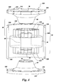
- FIG.5 the figure illustrates a three dimensional view 500 of stator housing cone section 310 according to one embodiment of the present invention.
- Stator housing cone section 310 is adapted to couple with a cylindrical stator housing wall 305 (See FIG.4 ) via fasteners (not shown) inserted into fastener cavities 320.
- Stator housing cone section 310 comprises an inwardly-facing stator wall 38 having an inner surface 70 and an outer surface 80.
- Barrier layer 90 is disposed on a portion of the inner surface 70 of inwardly-facing stator wall 38 and is adapted to shield a portion of the inwardly-facing stator wall from the magnetic field associated with stator armature end-windings 34 (See FIG.4 ).
- FIG. 4 the embodiment shown in FIG.
- the barrier layer 90 is a cone-shaped band of copper disposed on inner surface 70.
- the stator housing cone section is adapted to couple with an end portion of the ceramic bore tube, the inner surface of stator housing cone section being coupled to an outer surface of the ceramic bore tube.
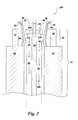
- the model system 600 studied included a portion of an encapsulated stator assembly comprising a stator end region containing stator armature end-windings 34 separated from an interior volume 50 by an inwardly-facing stator wall 38 and a barrier layer 90.
- the inwardly-facing stator wall was treated as comprised of INCONEL and the barrier layer was copper metal.
- the inwardly-facing stator wall 38 was divided into 6 sections; a seal holder section having the dimensions indicated and serving to connect the inwardly-facing stator wall to the ceramic bore tube 40, and sections Cone_Inc_3 to Cone_Inc_7 (See FIG.6 ).
- the inner surface of the inwardly-facing stator wall was clad in copper metal having a uniform thickness of about 0.110 inches and was divided conceptually into the six sections shown in FIG.6 (Cone_Cu_1 to Cone_Cu_6).
- the model system also included two additional features which are present in certain embodiments of the present invention; a bearing holder and a bearing case adapted for use with a magnetic bearing (not shown).
Landscapes
- Engineering & Computer Science (AREA)
- Power Engineering (AREA)
- Physics & Mathematics (AREA)
- Electromagnetism (AREA)
- Motor Or Generator Frames (AREA)
- Connection Of Motors, Electrical Generators, Mechanical Devices, And The Like (AREA)
- Iron Core Of Rotating Electric Machines (AREA)
- Permanent Magnet Type Synchronous Machine (AREA)
- Sliding-Contact Bearings (AREA)
Applications Claiming Priority (1)
| Application Number | Priority Date | Filing Date | Title |
|---|---|---|---|
| US12/942,204 US20120112571A1 (en) | 2010-11-09 | 2010-11-09 | Encapsulated stator assembly |
Publications (2)
| Publication Number | Publication Date |
|---|---|
| EP2451053A2 true EP2451053A2 (de) | 2012-05-09 |
| EP2451053A3 EP2451053A3 (de) | 2012-07-11 |
Family
ID=45400874
Family Applications (1)
| Application Number | Title | Priority Date | Filing Date |
|---|---|---|---|
| EP11188068A Withdrawn EP2451053A3 (de) | 2010-11-09 | 2011-11-07 | Eingekapselte Statoranordnung |
Country Status (5)
| Country | Link |
|---|---|
| US (1) | US20120112571A1 (de) |
| EP (1) | EP2451053A3 (de) |
| JP (1) | JP5920969B2 (de) |
| CN (1) | CN102570639A (de) |
| RU (1) | RU2580948C2 (de) |
Families Citing this family (12)
| Publication number | Priority date | Publication date | Assignee | Title |
|---|---|---|---|---|
| US9819248B2 (en) | 2012-12-31 | 2017-11-14 | Teco-Westinghouse Motor Company | Assemblies and methods for cooling electric machines |
| US9537375B2 (en) * | 2013-05-10 | 2017-01-03 | General Electric Company | Thermal conductor for use in an electric machine and method of forming the same |
| US9475381B2 (en) | 2013-05-15 | 2016-10-25 | Ford Global Technologies, Llc | System and method for reducing power train air resistance |
| CN103545963A (zh) * | 2013-10-25 | 2014-01-29 | 中电电机股份有限公司 | 同步发电机定子端部电屏蔽结构 |
| US9543814B2 (en) | 2014-01-07 | 2017-01-10 | Ge Aviation Systems Llc | Method of making a heat transfer element for an electric machine |
| US9509194B2 (en) * | 2014-01-07 | 2016-11-29 | Ge Aviation Systems Llc | Generator assembly |
| JP6087427B2 (ja) * | 2014-10-02 | 2017-03-01 | 三菱電機株式会社 | 回転電機の回転子及び回転電機の回転子の製造方法 |
| DE102014222123A1 (de) * | 2014-10-29 | 2016-05-04 | Robert Bosch Gmbh | Elektrische Asynchronmaschine |
| DE102014018338A1 (de) * | 2014-12-10 | 2016-06-16 | Audi Ag | Elektrische Maschine und Kraftfahrzeug |
| CN107846116A (zh) * | 2016-09-18 | 2018-03-27 | 德昌电机(深圳)有限公司 | 电机及电机组件 |
| US12365030B2 (en) * | 2020-09-29 | 2025-07-22 | The Boeing Company | Multi-property monolithic stainless steel component |
| EP4280429A1 (de) | 2022-05-17 | 2023-11-22 | Hamilton Sundstrand Corporation | Keramische hülse für ein statorgehäuse einer elektrischen maschine |
Citations (4)
| Publication number | Priority date | Publication date | Assignee | Title |
|---|---|---|---|---|
| GB898249A (en) * | 1959-08-13 | 1962-06-06 | Ass Elect Ind | Improvements relating to dynamo electric machines |
| JPS6091840A (ja) * | 1983-10-21 | 1985-05-23 | Hitachi Ltd | 回転電機の通風冷却装置 |
| JPS60245436A (ja) * | 1984-05-18 | 1985-12-05 | Toshiba Corp | 回転電機のシ−ルド板 |
| EP1863152A2 (de) * | 2006-06-02 | 2007-12-05 | General Electric Company | Verfahren und Vorrichtungen zur Verwendung eines elektrischen Gerätes zum Leiten von Flüssigkeiten durch eine Pipeline |
Family Cites Families (25)
| Publication number | Priority date | Publication date | Assignee | Title |
|---|---|---|---|---|
| BE524566A (de) * | ||||
| CA584954A (en) * | 1954-07-01 | 1959-10-13 | Westinghouse Electric Corporation | Motor pump unit |
| US3368087A (en) * | 1963-08-16 | 1968-02-06 | Asea Ab | Rotating electric high power machine with super-conducting stator |
| JPS5337801A (en) * | 1976-09-20 | 1978-04-07 | Toshiba Corp | Rotating machine |
| JPS5996843A (ja) * | 1982-11-19 | 1984-06-04 | Hitachi Ltd | 水中モータ |
| JPS59129553A (ja) * | 1983-01-13 | 1984-07-25 | Toshiba Corp | 回転電機 |
| SU1185497A1 (ru) * | 1983-11-09 | 1985-10-15 | Н.А. Куцью | Статор закрытой электрической машины |
| JPH07111752A (ja) * | 1993-10-08 | 1995-04-25 | Ebara Corp | マグネットポンプ |
| US5714814A (en) * | 1993-11-29 | 1998-02-03 | Askoll S.P.A. | Support for the rotor shaft of a centrifugal pump with permanent-magnet electric motor |
| FR2745436B1 (fr) * | 1996-02-28 | 1998-04-03 | Elf Aquitaine | Generateur d'energie electrique en ligne autonome |
| US6202285B1 (en) * | 1998-01-16 | 2001-03-20 | Reliance Electric Technologies, Llc | Electric motor having electrostatic shield arrangement |
| US6373921B1 (en) * | 1999-12-27 | 2002-04-16 | General Electric Company | X-ray unit including electromagnetic shield |
| DE10039964A1 (de) * | 2000-08-16 | 2002-03-07 | Siemens Ag | Supraleitungseinrichtung mit einer Kälteeinheit zur Kühlung einer rotierenden, supraleitenden Wicklung |
| JP4018981B2 (ja) * | 2000-10-09 | 2007-12-05 | シーメンス アクチエンゲゼルシヤフト | ロータとロータを無接触で支持する磁気軸受を備える装置 |
| DE10057664A1 (de) * | 2000-11-21 | 2002-05-29 | Siemens Ag | Supraleitungseinrichtung mit einem thermisch an eine rotierende,supraleitende Wicklung angekoppelten Kaltkopf einer Kälteeinheit |
| US6795720B2 (en) * | 2001-08-24 | 2004-09-21 | General Electric Company | High temperature superconducting synchronous rotor coil having multi-piece rotor core |
| US7272938B2 (en) * | 2002-03-14 | 2007-09-25 | Siemens Aktiengesellschaft | Superconducting device with a cold head of a refrigeration unit with a thermosyphon effect thermally coupled to a rotating superconducting winding |
| NL1021656C2 (nl) * | 2002-10-15 | 2004-04-16 | Siemens Demag Delaval Turbomac | Compressoreenheid met gemeenschappelijke behuizing voor elektromotor en compressor, werkwijze voor het vervaardigen van een scheidingswand voor een compressoreenheid en gebruik van een compressoreenheid. |
| JP3970260B2 (ja) * | 2004-04-23 | 2007-09-05 | 三菱重工業株式会社 | ポンプ |
| DE102005005283A1 (de) * | 2005-02-04 | 2006-08-17 | Siemens Ag | Maschinenanlage mit Thermosyphon-Kühlung ihrer supraleitenden Rotorwicklung |
| US7508101B2 (en) * | 2006-02-24 | 2009-03-24 | General Electric Company | Methods and apparatus for using an electrical machine to transport fluids through a pipeline |
| TW200816601A (en) * | 2006-09-29 | 2008-04-01 | Sunonwealth Electr Mach Ind Co | Motor structure |
| US20080197731A1 (en) * | 2007-02-15 | 2008-08-21 | Nidec Corporation | Brushless motor and pump mounted with brushless motor |
| US7847454B2 (en) * | 2007-03-08 | 2010-12-07 | General Electric Company | Encapsulated stator assembly and process for making |
| JP2009100522A (ja) * | 2007-10-16 | 2009-05-07 | Hitachi Ltd | 回転電機 |
-
2010
- 2010-11-09 US US12/942,204 patent/US20120112571A1/en not_active Abandoned
-
2011
- 2011-11-02 JP JP2011240721A patent/JP5920969B2/ja not_active Expired - Fee Related
- 2011-11-07 EP EP11188068A patent/EP2451053A3/de not_active Withdrawn
- 2011-11-08 RU RU2011144885/07A patent/RU2580948C2/ru not_active IP Right Cessation
- 2011-11-09 CN CN2011103670177A patent/CN102570639A/zh active Pending
Patent Citations (4)
| Publication number | Priority date | Publication date | Assignee | Title |
|---|---|---|---|---|
| GB898249A (en) * | 1959-08-13 | 1962-06-06 | Ass Elect Ind | Improvements relating to dynamo electric machines |
| JPS6091840A (ja) * | 1983-10-21 | 1985-05-23 | Hitachi Ltd | 回転電機の通風冷却装置 |
| JPS60245436A (ja) * | 1984-05-18 | 1985-12-05 | Toshiba Corp | 回転電機のシ−ルド板 |
| EP1863152A2 (de) * | 2006-06-02 | 2007-12-05 | General Electric Company | Verfahren und Vorrichtungen zur Verwendung eines elektrischen Gerätes zum Leiten von Flüssigkeiten durch eine Pipeline |
Also Published As
| Publication number | Publication date |
|---|---|
| RU2580948C2 (ru) | 2016-04-10 |
| CN102570639A (zh) | 2012-07-11 |
| JP5920969B2 (ja) | 2016-05-24 |
| US20120112571A1 (en) | 2012-05-10 |
| RU2011144885A (ru) | 2013-05-20 |
| JP2012105528A (ja) | 2012-05-31 |
| EP2451053A3 (de) | 2012-07-11 |
Similar Documents
| Publication | Publication Date | Title |
|---|---|---|
| EP2451053A2 (de) | Eingekapselte Statoranordnung | |
| US7768173B2 (en) | Apparatus for using an electrical machine to transport fluids through a pipeline | |
| US7508101B2 (en) | Methods and apparatus for using an electrical machine to transport fluids through a pipeline | |
| US7986070B2 (en) | Overmoulded or canned electrical machine | |
| CN101855809B (zh) | 高效凸极电机及其制造方法 | |
| US11476734B1 (en) | System, method and apparatus for direct liquid-cooled axial flux electric machine with multiple PCB stators | |
| JP2007282489A (ja) | 管路を通して流体を輸送するために電気機械を使用する方法および装置 | |
| GB2217118A (en) | Cooling dynamoelectric machines : anti burst rotor construction | |
| CN101410623A (zh) | 压缩机单元 | |
| KR100639808B1 (ko) | 방전 펌프 엑시머레이저장치 | |
| US12283863B2 (en) | System, method and apparatus for direct liquid-cooled axial flux electric machine with multiple PCB stators | |
| CN116260280A (zh) | 氢气膨胀器磁性发电机设备和方法 | |
| GB1577389A (en) | Annular linear induction pump with an externally supported duct | |
| US20060250037A1 (en) | Electrical machine having a stator that is enclosed in an explosion-proof manner | |
| US9035514B2 (en) | Jacketed electromagnetic machine stator for use in a corrosive atmosphere without heat treatment | |
| BRPI0615441A2 (pt) | dispositivo e método para segurar e travar imãs permanentes e melhorar resfriamento dentro de uma máquina elétrica rotativa | |
| JP4049531B2 (ja) | 磁気軸受モータおよびエキシマレーザ装置 | |
| RU2041547C1 (ru) | Торцевая электрическая машина ветохина (тэмв) | |
| RU2690019C1 (ru) | Инкапсулированная электрическая вращающаяся машина | |
| CA1333289C (en) | Annular linear induction pump with an externally supported duct | |
| RU110432U1 (ru) | Центробежный компрессорный агрегат | |
| JP2005245155A (ja) | 電動機冷却構造 | |
| JPH0727814Y2 (ja) | 真空ポンプ駆動用モ−タ | |
| Smetanin et al. | Investigation of the thermal state of an asynchronous motor with an asymmetric magnetic circuit | |
| US7525223B2 (en) | Induction motor having the rotor located within a shell |
Legal Events
| Date | Code | Title | Description |
|---|---|---|---|
| PUAI | Public reference made under article 153(3) epc to a published international application that has entered the european phase |
Free format text: ORIGINAL CODE: 0009012 |
|
| AK | Designated contracting states |
Kind code of ref document: A2 Designated state(s): AL AT BE BG CH CY CZ DE DK EE ES FI FR GB GR HR HU IE IS IT LI LT LU LV MC MK MT NL NO PL PT RO RS SE SI SK SM TR |
|
| AX | Request for extension of the european patent |
Extension state: BA ME |
|
| PUAL | Search report despatched |
Free format text: ORIGINAL CODE: 0009013 |
|
| AK | Designated contracting states |
Kind code of ref document: A3 Designated state(s): AL AT BE BG CH CY CZ DE DK EE ES FI FR GB GR HR HU IE IS IT LI LT LU LV MC MK MT NL NO PL PT RO RS SE SI SK SM TR |
|
| AX | Request for extension of the european patent |
Extension state: BA ME |
|
| RIC1 | Information provided on ipc code assigned before grant |
Ipc: H02K 11/00 20060101ALI20120606BHEP Ipc: H02K 5/128 20060101AFI20120606BHEP Ipc: H02K 3/42 20060101ALN20120606BHEP |
|
| 17P | Request for examination filed |
Effective date: 20130111 |
|
| 17Q | First examination report despatched |
Effective date: 20150901 |
|
| STAA | Information on the status of an ep patent application or granted ep patent |
Free format text: STATUS: THE APPLICATION IS DEEMED TO BE WITHDRAWN |
|
| 18D | Application deemed to be withdrawn |
Effective date: 20160312 |