EP2449171B1 - Merhlitziges stahlkabel wobei die zweilagigen litzen mit kunststoff wàhrend der produktion versehen werden - Google Patents
Merhlitziges stahlkabel wobei die zweilagigen litzen mit kunststoff wàhrend der produktion versehen werden Download PDFInfo
- Publication number
- EP2449171B1 EP2449171B1 EP10737302.9A EP10737302A EP2449171B1 EP 2449171 B1 EP2449171 B1 EP 2449171B1 EP 10737302 A EP10737302 A EP 10737302A EP 2449171 B1 EP2449171 B1 EP 2449171B1
- Authority
- EP
- European Patent Office
- Prior art keywords
- strand
- strands
- rubber
- inner layer
- wires
- Prior art date
- Legal status (The legal status is an assumption and is not a legal conclusion. Google has not performed a legal analysis and makes no representation as to the accuracy of the status listed.)
- Active
Links
- 238000011065 in-situ storage Methods 0.000 title claims description 24
- 229920001971 elastomer Polymers 0.000 claims description 120
- 238000010276 construction Methods 0.000 claims description 61
- 239000000203 mixture Substances 0.000 claims description 32
- 238000012360 testing method Methods 0.000 claims description 19
- 229910052751 metal Inorganic materials 0.000 claims description 16
- 239000002184 metal Substances 0.000 claims description 16
- 239000000806 elastomer Substances 0.000 claims description 12
- 229920001577 copolymer Polymers 0.000 claims description 11
- 229920003244 diene elastomer Polymers 0.000 claims description 10
- RRHGJUQNOFWUDK-UHFFFAOYSA-N Isoprene Natural products CC(=C)C=C RRHGJUQNOFWUDK-UHFFFAOYSA-N 0.000 claims description 9
- 244000043261 Hevea brasiliensis Species 0.000 claims description 7
- 150000001875 compounds Chemical class 0.000 claims description 7
- 229920003052 natural elastomer Polymers 0.000 claims description 7
- 229920001194 natural rubber Polymers 0.000 claims description 7
- 230000035699 permeability Effects 0.000 claims description 7
- 229920003051 synthetic elastomer Polymers 0.000 claims description 6
- 229920006395 saturated elastomer Polymers 0.000 claims description 3
- KAKZBPTYRLMSJV-UHFFFAOYSA-N vinyl-ethylene Natural products C=CC=C KAKZBPTYRLMSJV-UHFFFAOYSA-N 0.000 claims description 3
- 229920002857 polybutadiene Polymers 0.000 claims description 2
- 238000004519 manufacturing process Methods 0.000 description 33
- 230000002787 reinforcement Effects 0.000 description 20
- 238000000034 method Methods 0.000 description 17
- 238000001125 extrusion Methods 0.000 description 14
- 238000009472 formulation Methods 0.000 description 12
- 229910000831 Steel Inorganic materials 0.000 description 11
- 238000005259 measurement Methods 0.000 description 11
- 238000005201 scrubbing Methods 0.000 description 11
- 239000010959 steel Substances 0.000 description 11
- 238000005260 corrosion Methods 0.000 description 10
- 230000003014 reinforcing effect Effects 0.000 description 10
- 238000004132 cross linking Methods 0.000 description 9
- 238000005253 cladding Methods 0.000 description 8
- 238000004073 vulcanization Methods 0.000 description 8
- 229910000975 Carbon steel Inorganic materials 0.000 description 7
- 239000011324 bead Substances 0.000 description 7
- 239000010962 carbon steel Substances 0.000 description 7
- 239000011248 coating agent Substances 0.000 description 7
- 238000000576 coating method Methods 0.000 description 7
- 239000011159 matrix material Substances 0.000 description 7
- 230000035515 penetration Effects 0.000 description 7
- 238000011144 upstream manufacturing Methods 0.000 description 7
- XLYOFNOQVPJJNP-UHFFFAOYSA-N water Substances O XLYOFNOQVPJJNP-UHFFFAOYSA-N 0.000 description 7
- VYPSYNLAJGMNEJ-UHFFFAOYSA-N Silicium dioxide Chemical compound O=[Si]=O VYPSYNLAJGMNEJ-UHFFFAOYSA-N 0.000 description 6
- 239000006229 carbon black Substances 0.000 description 6
- 235000019241 carbon black Nutrition 0.000 description 6
- 230000007797 corrosion Effects 0.000 description 6
- 238000004804 winding Methods 0.000 description 6
- 229910001369 Brass Inorganic materials 0.000 description 5
- 239000010951 brass Substances 0.000 description 5
- 239000003795 chemical substances by application Substances 0.000 description 5
- 239000000470 constituent Substances 0.000 description 5
- OKTJSMMVPCPJKN-UHFFFAOYSA-N Carbon Chemical compound [C] OKTJSMMVPCPJKN-UHFFFAOYSA-N 0.000 description 4
- NINIDFKCEFEMDL-UHFFFAOYSA-N Sulfur Chemical compound [S] NINIDFKCEFEMDL-UHFFFAOYSA-N 0.000 description 4
- 230000015572 biosynthetic process Effects 0.000 description 4
- 229910052799 carbon Inorganic materials 0.000 description 4
- PXHVJJICTQNCMI-UHFFFAOYSA-N nickel Substances [Ni] PXHVJJICTQNCMI-UHFFFAOYSA-N 0.000 description 4
- 238000005096 rolling process Methods 0.000 description 4
- 229910052717 sulfur Inorganic materials 0.000 description 4
- 239000011593 sulfur Substances 0.000 description 4
- 229910052725 zinc Inorganic materials 0.000 description 4
- 239000011701 zinc Substances 0.000 description 4
- HCHKCACWOHOZIP-UHFFFAOYSA-N Zinc Chemical compound [Zn] HCHKCACWOHOZIP-UHFFFAOYSA-N 0.000 description 3
- 229910045601 alloy Inorganic materials 0.000 description 3
- 239000000956 alloy Substances 0.000 description 3
- 238000003490 calendering Methods 0.000 description 3
- 239000004020 conductor Substances 0.000 description 3
- 150000001993 dienes Chemical class 0.000 description 3
- 230000000694 effects Effects 0.000 description 3
- 238000010438 heat treatment Methods 0.000 description 3
- 239000011256 inorganic filler Substances 0.000 description 3
- 229910003475 inorganic filler Inorganic materials 0.000 description 3
- 229910052759 nickel Inorganic materials 0.000 description 3
- 229920001195 polyisoprene Polymers 0.000 description 3
- 229920005989 resin Polymers 0.000 description 3
- 239000011347 resin Substances 0.000 description 3
- 239000011265 semifinished product Substances 0.000 description 3
- IJGRMHOSHXDMSA-UHFFFAOYSA-N Atomic nitrogen Chemical compound N#N IJGRMHOSHXDMSA-UHFFFAOYSA-N 0.000 description 2
- 241001589086 Bellapiscis medius Species 0.000 description 2
- LFQSCWFLJHTTHZ-UHFFFAOYSA-N Ethanol Chemical compound CCO LFQSCWFLJHTTHZ-UHFFFAOYSA-N 0.000 description 2
- XEEYBQQBJWHFJM-UHFFFAOYSA-N Iron Chemical compound [Fe] XEEYBQQBJWHFJM-UHFFFAOYSA-N 0.000 description 2
- CDBYLPFSWZWCQE-UHFFFAOYSA-L Sodium Carbonate Chemical compound [Na+].[Na+].[O-]C([O-])=O CDBYLPFSWZWCQE-UHFFFAOYSA-L 0.000 description 2
- 239000000654 additive Substances 0.000 description 2
- 239000002318 adhesion promoter Substances 0.000 description 2
- 230000016571 aggressive behavior Effects 0.000 description 2
- 229910052782 aluminium Inorganic materials 0.000 description 2
- 239000003963 antioxidant agent Substances 0.000 description 2
- 125000003118 aryl group Chemical group 0.000 description 2
- 238000007906 compression Methods 0.000 description 2
- 230000006835 compression Effects 0.000 description 2
- 238000000151 deposition Methods 0.000 description 2
- 238000009826 distribution Methods 0.000 description 2
- 239000003792 electrolyte Substances 0.000 description 2
- 239000004744 fabric Substances 0.000 description 2
- 239000012530 fluid Substances 0.000 description 2
- 238000010348 incorporation Methods 0.000 description 2
- 238000009434 installation Methods 0.000 description 2
- 238000005065 mining Methods 0.000 description 2
- 239000003921 oil Substances 0.000 description 2
- 230000003071 parasitic effect Effects 0.000 description 2
- 239000000047 product Substances 0.000 description 2
- 230000002829 reductive effect Effects 0.000 description 2
- 239000012763 reinforcing filler Substances 0.000 description 2
- GHMLBKRAJCXXBS-UHFFFAOYSA-N resorcinol Chemical compound OC1=CC=CC(O)=C1 GHMLBKRAJCXXBS-UHFFFAOYSA-N 0.000 description 2
- 150000003839 salts Chemical class 0.000 description 2
- 239000000377 silicon dioxide Substances 0.000 description 2
- 239000010935 stainless steel Substances 0.000 description 2
- 229910001220 stainless steel Inorganic materials 0.000 description 2
- 229920003048 styrene butadiene rubber Polymers 0.000 description 2
- 229920002725 thermoplastic elastomer Polymers 0.000 description 2
- XQUPVDVFXZDTLT-UHFFFAOYSA-N 1-[4-[[4-(2,5-dioxopyrrol-1-yl)phenyl]methyl]phenyl]pyrrole-2,5-dione Chemical compound O=C1C=CC(=O)N1C(C=C1)=CC=C1CC1=CC=C(N2C(C=CC2=O)=O)C=C1 XQUPVDVFXZDTLT-UHFFFAOYSA-N 0.000 description 1
- CBXRMKZFYQISIV-UHFFFAOYSA-N 1-n,1-n,1-n',1-n',2-n,2-n,2-n',2-n'-octamethylethene-1,1,2,2-tetramine Chemical compound CN(C)C(N(C)C)=C(N(C)C)N(C)C CBXRMKZFYQISIV-UHFFFAOYSA-N 0.000 description 1
- BNCADMBVWNPPIZ-UHFFFAOYSA-N 2-n,2-n,4-n,4-n,6-n,6-n-hexakis(methoxymethyl)-1,3,5-triazine-2,4,6-triamine Chemical compound COCN(COC)C1=NC(N(COC)COC)=NC(N(COC)COC)=N1 BNCADMBVWNPPIZ-UHFFFAOYSA-N 0.000 description 1
- 206010001488 Aggression Diseases 0.000 description 1
- VYZAMTAEIAYCRO-UHFFFAOYSA-N Chromium Chemical compound [Cr] VYZAMTAEIAYCRO-UHFFFAOYSA-N 0.000 description 1
- 239000006237 Intermediate SAF Substances 0.000 description 1
- 150000001206 Neodymium Chemical class 0.000 description 1
- 229920006978 SSBR Polymers 0.000 description 1
- 235000021355 Stearic acid Nutrition 0.000 description 1
- 241000897276 Termes Species 0.000 description 1
- 229910007565 Zn—Cu Inorganic materials 0.000 description 1
- 239000002250 absorbent Substances 0.000 description 1
- 230000002745 absorbent Effects 0.000 description 1
- 239000000370 acceptor Substances 0.000 description 1
- 230000004308 accommodation Effects 0.000 description 1
- 230000032683 aging Effects 0.000 description 1
- PNEYBMLMFCGWSK-UHFFFAOYSA-N aluminium oxide Inorganic materials [O-2].[O-2].[O-2].[Al+3].[Al+3] PNEYBMLMFCGWSK-UHFFFAOYSA-N 0.000 description 1
- 230000003712 anti-aging effect Effects 0.000 description 1
- 230000003078 antioxidant effect Effects 0.000 description 1
- 239000007864 aqueous solution Substances 0.000 description 1
- 239000010692 aromatic oil Substances 0.000 description 1
- QVGXLLKOCUKJST-UHFFFAOYSA-N atomic oxygen Chemical compound [O] QVGXLLKOCUKJST-UHFFFAOYSA-N 0.000 description 1
- 239000003518 caustics Substances 0.000 description 1
- 238000012512 characterization method Methods 0.000 description 1
- 229910052804 chromium Inorganic materials 0.000 description 1
- 239000011651 chromium Substances 0.000 description 1
- 238000003776 cleavage reaction Methods 0.000 description 1
- 150000001868 cobalt Chemical class 0.000 description 1
- 229910017052 cobalt Inorganic materials 0.000 description 1
- 239000010941 cobalt Substances 0.000 description 1
- GUTLYIVDDKVIGB-UHFFFAOYSA-N cobalt atom Chemical compound [Co] GUTLYIVDDKVIGB-UHFFFAOYSA-N 0.000 description 1
- 238000010622 cold drawing Methods 0.000 description 1
- 230000008094 contradictory effect Effects 0.000 description 1
- 238000010411 cooking Methods 0.000 description 1
- 229910052802 copper Inorganic materials 0.000 description 1
- TVZPLCNGKSPOJA-UHFFFAOYSA-N copper zinc Chemical compound [Cu].[Zn] TVZPLCNGKSPOJA-UHFFFAOYSA-N 0.000 description 1
- 239000007822 coupling agent Substances 0.000 description 1
- 238000005336 cracking Methods 0.000 description 1
- 230000007850 degeneration Effects 0.000 description 1
- 238000005238 degreasing Methods 0.000 description 1
- 230000008021 deposition Effects 0.000 description 1
- 238000009792 diffusion process Methods 0.000 description 1
- 239000006185 dispersion Substances 0.000 description 1
- 238000005868 electrolysis reaction Methods 0.000 description 1
- 239000000839 emulsion Substances 0.000 description 1
- 238000007720 emulsion polymerization reaction Methods 0.000 description 1
- 239000000945 filler Substances 0.000 description 1
- 238000010304 firing Methods 0.000 description 1
- 239000006260 foam Substances 0.000 description 1
- 239000000446 fuel Substances 0.000 description 1
- 229910021485 fumed silica Inorganic materials 0.000 description 1
- 229920001519 homopolymer Polymers 0.000 description 1
- 238000005470 impregnation Methods 0.000 description 1
- 239000012535 impurity Substances 0.000 description 1
- 238000012432 intermediate storage Methods 0.000 description 1
- 229910052742 iron Inorganic materials 0.000 description 1
- 229920003049 isoprene rubber Polymers 0.000 description 1
- -1 lanthanide salts Chemical class 0.000 description 1
- 229910052747 lanthanoid Inorganic materials 0.000 description 1
- 230000000670 limiting effect Effects 0.000 description 1
- 239000000314 lubricant Substances 0.000 description 1
- 239000000463 material Substances 0.000 description 1
- 230000008018 melting Effects 0.000 description 1
- 238000002844 melting Methods 0.000 description 1
- 239000007769 metal material Substances 0.000 description 1
- 125000000325 methylidene group Chemical group [H]C([H])=* 0.000 description 1
- 239000012764 mineral filler Substances 0.000 description 1
- GEMHFKXPOCTAIP-UHFFFAOYSA-N n,n-dimethyl-n'-phenylcarbamimidoyl chloride Chemical compound CN(C)C(Cl)=NC1=CC=CC=C1 GEMHFKXPOCTAIP-UHFFFAOYSA-N 0.000 description 1
- 150000002815 nickel Chemical class 0.000 description 1
- 229910052757 nitrogen Inorganic materials 0.000 description 1
- QIQXTHQIDYTFRH-UHFFFAOYSA-N octadecanoic acid Chemical compound CCCCCCCCCCCCCCCCCC(O)=O QIQXTHQIDYTFRH-UHFFFAOYSA-N 0.000 description 1
- OQCDKBAXFALNLD-UHFFFAOYSA-N octadecanoic acid Natural products CCCCCCCC(C)CCCCCCCCC(O)=O OQCDKBAXFALNLD-UHFFFAOYSA-N 0.000 description 1
- 229910052760 oxygen Inorganic materials 0.000 description 1
- 239000001301 oxygen Substances 0.000 description 1
- 230000036961 partial effect Effects 0.000 description 1
- 239000002245 particle Substances 0.000 description 1
- 238000005192 partition Methods 0.000 description 1
- 238000005554 pickling Methods 0.000 description 1
- 239000004033 plastic Substances 0.000 description 1
- 229920003023 plastic Polymers 0.000 description 1
- BASFCYQUMIYNBI-UHFFFAOYSA-N platinum Chemical compound [Pt] BASFCYQUMIYNBI-UHFFFAOYSA-N 0.000 description 1
- 229920003192 poly(bis maleimide) Polymers 0.000 description 1
- 229920000642 polymer Polymers 0.000 description 1
- 229920003225 polyurethane elastomer Polymers 0.000 description 1
- 238000012545 processing Methods 0.000 description 1
- 230000002250 progressing effect Effects 0.000 description 1
- 230000000750 progressive effect Effects 0.000 description 1
- 230000002035 prolonged effect Effects 0.000 description 1
- 230000001737 promoting effect Effects 0.000 description 1
- 238000009877 rendering Methods 0.000 description 1
- 238000011160 research Methods 0.000 description 1
- 230000002441 reversible effect Effects 0.000 description 1
- 230000007017 scission Effects 0.000 description 1
- 238000000926 separation method Methods 0.000 description 1
- 229910000029 sodium carbonate Inorganic materials 0.000 description 1
- 239000007787 solid Substances 0.000 description 1
- 239000000243 solution Substances 0.000 description 1
- 125000006850 spacer group Chemical group 0.000 description 1
- 239000008117 stearic acid Substances 0.000 description 1
- 238000009628 steelmaking Methods 0.000 description 1
- 238000003860 storage Methods 0.000 description 1
- 238000005482 strain hardening Methods 0.000 description 1
- QAZLUNIWYYOJPC-UHFFFAOYSA-M sulfenamide Chemical compound [Cl-].COC1=C(C)C=[N+]2C3=NC4=CC=C(OC)C=C4N3SCC2=C1C QAZLUNIWYYOJPC-UHFFFAOYSA-M 0.000 description 1
- 230000001360 synchronised effect Effects 0.000 description 1
- 239000004753 textile Substances 0.000 description 1
- 229910052718 tin Inorganic materials 0.000 description 1
- 238000012549 training Methods 0.000 description 1
- 230000001131 transforming effect Effects 0.000 description 1
- 239000012936 vulcanization activator Substances 0.000 description 1
Images


Classifications
-
- D—TEXTILES; PAPER
- D07—ROPES; CABLES OTHER THAN ELECTRIC
- D07B—ROPES OR CABLES IN GENERAL
- D07B1/00—Constructional features of ropes or cables
- D07B1/06—Ropes or cables built-up from metal wires, e.g. of section wires around a hemp core
-
- D—TEXTILES; PAPER
- D07—ROPES; CABLES OTHER THAN ELECTRIC
- D07B—ROPES OR CABLES IN GENERAL
- D07B1/00—Constructional features of ropes or cables
- D07B1/06—Ropes or cables built-up from metal wires, e.g. of section wires around a hemp core
- D07B1/0606—Reinforcing cords for rubber or plastic articles
- D07B1/0613—Reinforcing cords for rubber or plastic articles the reinforcing cords being characterised by the rope configuration
-
- B—PERFORMING OPERATIONS; TRANSPORTING
- B60—VEHICLES IN GENERAL
- B60C—VEHICLE TYRES; TYRE INFLATION; TYRE CHANGING; CONNECTING VALVES TO INFLATABLE ELASTIC BODIES IN GENERAL; DEVICES OR ARRANGEMENTS RELATED TO TYRES
- B60C9/00—Reinforcements or ply arrangement of pneumatic tyres
- B60C9/18—Structure or arrangement of belts or breakers, crown-reinforcing or cushioning layers
- B60C9/20—Structure or arrangement of belts or breakers, crown-reinforcing or cushioning layers built-up from rubberised plies each having all cords arranged substantially parallel
-
- D—TEXTILES; PAPER
- D07—ROPES; CABLES OTHER THAN ELECTRIC
- D07B—ROPES OR CABLES IN GENERAL
- D07B1/00—Constructional features of ropes or cables
- D07B1/16—Ropes or cables with an enveloping sheathing or inlays of rubber or plastics
-
- D—TEXTILES; PAPER
- D07—ROPES; CABLES OTHER THAN ELECTRIC
- D07B—ROPES OR CABLES IN GENERAL
- D07B1/00—Constructional features of ropes or cables
- D07B1/16—Ropes or cables with an enveloping sheathing or inlays of rubber or plastics
- D07B1/165—Ropes or cables with an enveloping sheathing or inlays of rubber or plastics characterised by a plastic or rubber inlay
-
- D—TEXTILES; PAPER
- D07—ROPES; CABLES OTHER THAN ELECTRIC
- D07B—ROPES OR CABLES IN GENERAL
- D07B7/00—Details of, or auxiliary devices incorporated in, rope- or cable-making machines; Auxiliary apparatus associated with such machines
- D07B7/02—Machine details; Auxiliary devices
- D07B7/14—Machine details; Auxiliary devices for coating or wrapping ropes, cables, or component strands thereof
-
- D—TEXTILES; PAPER
- D07—ROPES; CABLES OTHER THAN ELECTRIC
- D07B—ROPES OR CABLES IN GENERAL
- D07B1/00—Constructional features of ropes or cables
- D07B1/06—Ropes or cables built-up from metal wires, e.g. of section wires around a hemp core
- D07B1/0606—Reinforcing cords for rubber or plastic articles
- D07B1/062—Reinforcing cords for rubber or plastic articles the reinforcing cords being characterised by the strand configuration
- D07B1/0626—Reinforcing cords for rubber or plastic articles the reinforcing cords being characterised by the strand configuration the reinforcing cords consisting of three core wires or filaments and at least one layer of outer wires or filaments, i.e. a 3+N configuration
-
- D—TEXTILES; PAPER
- D07—ROPES; CABLES OTHER THAN ELECTRIC
- D07B—ROPES OR CABLES IN GENERAL
- D07B2201/00—Ropes or cables
- D07B2201/10—Rope or cable structures
- D07B2201/1012—Rope or cable structures characterised by their internal structure
- D07B2201/102—Rope or cable structures characterised by their internal structure including a core
-
- D—TEXTILES; PAPER
- D07—ROPES; CABLES OTHER THAN ELECTRIC
- D07B—ROPES OR CABLES IN GENERAL
- D07B2201/00—Ropes or cables
- D07B2201/10—Rope or cable structures
- D07B2201/1028—Rope or cable structures characterised by the number of strands
- D07B2201/1032—Rope or cable structures characterised by the number of strands three to eight strands respectively forming a single layer
-
- D—TEXTILES; PAPER
- D07—ROPES; CABLES OTHER THAN ELECTRIC
- D07B—ROPES OR CABLES IN GENERAL
- D07B2201/00—Ropes or cables
- D07B2201/10—Rope or cable structures
- D07B2201/104—Rope or cable structures twisted
- D07B2201/1044—Rope or cable structures twisted characterised by a value or range of the pitch parameter given
-
- D—TEXTILES; PAPER
- D07—ROPES; CABLES OTHER THAN ELECTRIC
- D07B—ROPES OR CABLES IN GENERAL
- D07B2201/00—Ropes or cables
- D07B2201/20—Rope or cable components
- D07B2201/2001—Wires or filaments
- D07B2201/201—Wires or filaments characterised by a coating
- D07B2201/2011—Wires or filaments characterised by a coating comprising metals
-
- D—TEXTILES; PAPER
- D07—ROPES; CABLES OTHER THAN ELECTRIC
- D07B—ROPES OR CABLES IN GENERAL
- D07B2201/00—Ropes or cables
- D07B2201/20—Rope or cable components
- D07B2201/2015—Strands
- D07B2201/2023—Strands with core
-
- D—TEXTILES; PAPER
- D07—ROPES; CABLES OTHER THAN ELECTRIC
- D07B—ROPES OR CABLES IN GENERAL
- D07B2201/00—Ropes or cables
- D07B2201/20—Rope or cable components
- D07B2201/2015—Strands
- D07B2201/2024—Strands twisted
- D07B2201/2027—Compact winding
- D07B2201/2028—Compact winding having the same lay direction and lay pitch
-
- D—TEXTILES; PAPER
- D07—ROPES; CABLES OTHER THAN ELECTRIC
- D07B—ROPES OR CABLES IN GENERAL
- D07B2201/00—Ropes or cables
- D07B2201/20—Rope or cable components
- D07B2201/2015—Strands
- D07B2201/2024—Strands twisted
- D07B2201/2029—Open winding
- D07B2201/203—Cylinder winding, i.e. S/Z or Z/S
-
- D—TEXTILES; PAPER
- D07—ROPES; CABLES OTHER THAN ELECTRIC
- D07B—ROPES OR CABLES IN GENERAL
- D07B2201/00—Ropes or cables
- D07B2201/20—Rope or cable components
- D07B2201/2015—Strands
- D07B2201/2024—Strands twisted
- D07B2201/2029—Open winding
- D07B2201/2031—Different twist pitch
- D07B2201/2032—Different twist pitch compared with the core
-
- D—TEXTILES; PAPER
- D07—ROPES; CABLES OTHER THAN ELECTRIC
- D07B—ROPES OR CABLES IN GENERAL
- D07B2201/00—Ropes or cables
- D07B2201/20—Rope or cable components
- D07B2201/2015—Strands
- D07B2201/2038—Strands characterised by the number of wires or filaments
- D07B2201/2039—Strands characterised by the number of wires or filaments three to eight wires or filaments respectively forming a single layer
-
- D—TEXTILES; PAPER
- D07—ROPES; CABLES OTHER THAN ELECTRIC
- D07B—ROPES OR CABLES IN GENERAL
- D07B2201/00—Ropes or cables
- D07B2201/20—Rope or cable components
- D07B2201/2015—Strands
- D07B2201/2046—Strands comprising fillers
-
- D—TEXTILES; PAPER
- D07—ROPES; CABLES OTHER THAN ELECTRIC
- D07B—ROPES OR CABLES IN GENERAL
- D07B2201/00—Ropes or cables
- D07B2201/20—Rope or cable components
- D07B2201/2047—Cores
- D07B2201/2052—Cores characterised by their structure
- D07B2201/2059—Cores characterised by their structure comprising wires
- D07B2201/2061—Cores characterised by their structure comprising wires resulting in a twisted structure
-
- D—TEXTILES; PAPER
- D07—ROPES; CABLES OTHER THAN ELECTRIC
- D07B—ROPES OR CABLES IN GENERAL
- D07B2201/00—Ropes or cables
- D07B2201/20—Rope or cable components
- D07B2201/2047—Cores
- D07B2201/2052—Cores characterised by their structure
- D07B2201/2059—Cores characterised by their structure comprising wires
- D07B2201/2062—Cores characterised by their structure comprising wires comprising fillers
-
- D—TEXTILES; PAPER
- D07—ROPES; CABLES OTHER THAN ELECTRIC
- D07B—ROPES OR CABLES IN GENERAL
- D07B2201/00—Ropes or cables
- D07B2201/20—Rope or cable components
- D07B2201/2047—Cores
- D07B2201/2052—Cores characterised by their structure
- D07B2201/2065—Cores characterised by their structure comprising a coating
-
- D—TEXTILES; PAPER
- D07—ROPES; CABLES OTHER THAN ELECTRIC
- D07B—ROPES OR CABLES IN GENERAL
- D07B2201/00—Ropes or cables
- D07B2201/20—Rope or cable components
- D07B2201/2075—Fillers
- D07B2201/2079—Fillers characterised by the kind or amount of filling
- D07B2201/2081—Fillers characterised by the kind or amount of filling having maximum filling
-
- D—TEXTILES; PAPER
- D07—ROPES; CABLES OTHER THAN ELECTRIC
- D07B—ROPES OR CABLES IN GENERAL
- D07B2205/00—Rope or cable materials
- D07B2205/30—Inorganic materials
- D07B2205/3021—Metals
-
- D—TEXTILES; PAPER
- D07—ROPES; CABLES OTHER THAN ELECTRIC
- D07B—ROPES OR CABLES IN GENERAL
- D07B2205/00—Rope or cable materials
- D07B2205/30—Inorganic materials
- D07B2205/3021—Metals
- D07B2205/306—Aluminium (Al)
-
- D—TEXTILES; PAPER
- D07—ROPES; CABLES OTHER THAN ELECTRIC
- D07B—ROPES OR CABLES IN GENERAL
- D07B2205/00—Rope or cable materials
- D07B2205/30—Inorganic materials
- D07B2205/3021—Metals
- D07B2205/3067—Copper (Cu)
-
- D—TEXTILES; PAPER
- D07—ROPES; CABLES OTHER THAN ELECTRIC
- D07B—ROPES OR CABLES IN GENERAL
- D07B2205/00—Rope or cable materials
- D07B2205/30—Inorganic materials
- D07B2205/3021—Metals
- D07B2205/3071—Zinc (Zn)
-
- D—TEXTILES; PAPER
- D07—ROPES; CABLES OTHER THAN ELECTRIC
- D07B—ROPES OR CABLES IN GENERAL
- D07B2205/00—Rope or cable materials
- D07B2205/30—Inorganic materials
- D07B2205/3021—Metals
- D07B2205/3075—Tin (Sn)
-
- D—TEXTILES; PAPER
- D07—ROPES; CABLES OTHER THAN ELECTRIC
- D07B—ROPES OR CABLES IN GENERAL
- D07B2205/00—Rope or cable materials
- D07B2205/30—Inorganic materials
- D07B2205/3021—Metals
- D07B2205/3085—Alloys, i.e. non ferrous
- D07B2205/3089—Brass, i.e. copper (Cu) and zinc (Zn) alloys
-
- D—TEXTILES; PAPER
- D07—ROPES; CABLES OTHER THAN ELECTRIC
- D07B—ROPES OR CABLES IN GENERAL
- D07B2207/00—Rope or cable making machines
- D07B2207/40—Machine components
- D07B2207/4072—Means for mechanically reducing serpentining or mechanically killing of rope
-
- D—TEXTILES; PAPER
- D07—ROPES; CABLES OTHER THAN ELECTRIC
- D07B—ROPES OR CABLES IN GENERAL
- D07B2501/00—Application field
- D07B2501/20—Application field related to ropes or cables
- D07B2501/2046—Tire cords
-
- D—TEXTILES; PAPER
- D07—ROPES; CABLES OTHER THAN ELECTRIC
- D07B—ROPES OR CABLES IN GENERAL
- D07B7/00—Details of, or auxiliary devices incorporated in, rope- or cable-making machines; Auxiliary apparatus associated with such machines
- D07B7/02—Machine details; Auxiliary devices
- D07B7/14—Machine details; Auxiliary devices for coating or wrapping ropes, cables, or component strands thereof
- D07B7/145—Coating or filling-up interstices
Definitions
- the present invention relates to multi-rotor cables (" multistrand ropes" ) with very high mechanical strength, used in particular for the reinforcement of pneumatic tires for heavy industrial vehicles such as civil engineering vehicles of the mining type.
- a radial tire comprises in known manner a tread, two inextensible beads, two flanks connecting the beads to the tread and a belt circumferentially disposed between the carcass reinforcement and the tread.
- This belt consists of various plies (or “layers") of rubber reinforced or not by reinforcing elements (“reinforcements”) such as cords or monofilaments, metal or textile type.
- the belt is generally composed of several superimposed belt plies, sometimes called “working” plies or “crossed” plies, whose reinforcing cords, generally metallic, are arranged substantially parallel to each other inside a web, but crossed from one sheet to another, that is to say, inclined, symmetrically or otherwise, with respect to the median circumferential plane.
- These crossed plies are generally supplemented by various other plies or layers of auxiliary rubber, of varying widths depending on the case, with or without metal reinforcements; mention will be made in particular of so-called “protection” plies responsible for protecting the rest of the belt from external aggression, perforations, or “hooping” plies comprising metal reinforcements or non-oriented substantially in the circumferential direction (so-called plies). "zero degree”), whether radially external or internal to the crossed plies.
- the third requirement is particularly strong for tires for industrial vehicles such as heavy-duty vehicles or civil engineering vehicles, designed in particular to be retreaded once or more when their treads reach a critical degree of wear after rolling. or prolonged use.
- two-ply multistrand steel cables consisting of a core comprising J strand (s) forming an internal layer (Ci), J variant, are generally used. typically from 1 to 4, core around which are wound helically, in a helical pitch P K , K outer strands forming an outer layer (Ce) around said inner layer (Ci), as described for example in patents or patent applications US 5461850 , US 5768874 , US 6247514 , US 6817395 , US 6863103 , US 7426821 , US 2007/0144648 , WO 2008/026271 .
- these strand cables must be impregnated as much as possible by the rubber in the tire belts they reinforce, so that this rubber penetrates into the maximum of spaces between the constituent strands. the strands. If this penetration is insufficient, then empty channels remain along the strands, and corrosive agents, for example water, likely to penetrate the tires, for example as a result of cuts or other aggressions of the belt. pneumatic, run along these channels through said belt. The presence of this moisture plays an important role in causing corrosion and accelerating fatigue processes (phenomena known as "fatigue-corrosion”), compared to use in a dry atmosphere.
- the patent application US 2002/160213 has certainly proposed the realization of strands of the type gummed in situ.
- the method proposed herein consists of individually sheathing (ie, singly, "wire to wire") with raw rubber, upstream of the point of assembly (or twisting point) of the three wires, one or preferably each of the three son to obtain an inner layer sheathed rubber, before the subsequent introduction of the M son of the outer layer by wiring around the inner layer and sheathed.
- calendering consists in transforming the cable, by incorporation between two layers of rubber in the raw state, in a rubberized metal fabric as a semi-finished product for any subsequent manufacture, for example for the manufacture of a tire.
- the invention also relates to the use of such a multistrand cable for reinforcing articles or semi-finished products of rubber, for example webs, pipes, belts, conveyor belts, tires.
- the multistrand cable of the invention is particularly intended to be used as reinforcing element of a tire belt intended for industrial vehicles such as "heavy goods vehicles” - ie, subway, bus, road transport units (trucks, tractors, trailers), off-the-road vehicles -, agricultural or engineering machinery, other transport or handling vehicles.
- industrial vehicles such as "heavy goods vehicles” - ie, subway, bus, road transport units (trucks, tractors, trailers), off-the-road vehicles -, agricultural or engineering machinery, other transport or handling vehicles.
- the invention further relates to these articles or semi-finished rubber products themselves when reinforced by a multitoron cable according to the invention, in particular tires especially for industrial vehicles.
- Fm maximum load in N
- Rm tensile strength in MPa
- At total elongation in %
- the modulus measurements are carried out in tension, unless otherwise indicated according to the ASTM D 412 standard of 1998 (test piece “C”): one measures in second elongation (that is to say after a cycle of accommodation) the secant modulus "true” (that is to say, brought back to the real section of the specimen) at 10% elongation, denoted E10 and expressed in MPa (normal conditions of temperature and hygrometry according to ASTM D 1349 of 1999).
- the test is here carried out on strands extracted from the raw manufacturing multitasks cables, having undergone a subsequent coating and firing, or extracted from the tires or rubber sheets reinforced by these multistrand cables, thus already coated with rubber in the state cooked.
- the extracted strands must be, before the test, coated from the outside by a so-called coating gum.
- a series of 10 strands arranged in parallel is placed between two skims (two rectangles of 80 x 200 mm) of a rubber composition in the raw state, each skim having a thickness 3.5 mm; the whole is then locked in a mold, each of the strands being maintained under a sufficient tension (for example 2 daN) to ensure its straightness during the establishment in the mold, using clamping modules; then the vulcanization (baking) is carried out for 40 min at a temperature of 140 ° C and a pressure of 15 bar (rectangular piston 80 x 200 mm). Thereafter, the assembly is demoulded and cut strands 10 test pieces thus coated form of parallelepipeds 7 mm ⁇ 7 mm ⁇ L t, for characterization.
- the test is carried out over a predetermined length of strand L t (for example equal to P K , 3 cm or even 2 cm), thus coated by its surrounding rubber composition (or coating gum), as follows: air is sent to the inlet of the strand at a pressure of 1 bar, and the volume of air at the outlet is measured using a flow meter (calibrated, for example, from 0 to 500 cm 3 / min).
- a flow meter calibrated, for example, from 0 to 500 cm 3 / min.
- the strand sample is blocked in a compressed seal (eg a dense foam or rubber seal) such that only the amount of air passing through the strand from one end to the other, along its longitudinal axis, is taken into account by the measure; the tightness of the seal is checked beforehand with the aid of a solid rubber specimen, that is to say without strands.
- a compressed seal eg a dense foam or rubber seal
- the average air flow measured (average of the 10 specimens) is even lower than the longitudinal imperviousness of the strand is high.
- the amount of filling gum is measured by the difference between the weight of the initial strand (thus erased in situ) and the weight of the strand (and therefore that of its strands), the filling gum of which has been eliminated by a suitable electrolytic treatment.
- a sample of strand (length 1 m), coiled on itself to reduce its bulk, constitutes the cathode of an electrolyzer (connected to the negative terminal of a generator), while the anode (connected to the positive terminal ) consists of a platinum wire.
- the electrolyte consists of an aqueous solution (demineralized water) comprising 1 mole per liter of sodium carbonate.
- the sample immersed completely in the electrolyte, is energized for 15 min under a current of 300 mA.
- the strand is then removed from the bath, rinsed thoroughly with water. This treatment allows the rubber to be easily detached from the strand (if it is not the case, we continue the electrolysis for a few minutes).
- the eraser is carefully removed, for example by simple wiping with the aid of an absorbent fabric, while detaching one by one the son of the strand.
- the threads are rinsed with water again and then immersed in a beaker containing a mixture of demineralized water (50%) and ethanol (50%); the beaker is immersed in an ultrasonic tank for 10 minutes.
- the yarns thus devoid of any trace of gum are removed from the beaker, dried under a stream of nitrogen or air, and finally weighed.
- the fill rate in the strand expressed in mg (milligram) of filling gum per g (gram) of initial strand, is calculated and averaged over 10 measurements (i.e. meters of strand in total).
- any range of values designated by the expression "between a and b" represents the range of values from more than a to less than b (i.e. terminals a and b excluded) while any range of values designated by the term “from a to b” means the range from a to b (i.e., including the strict limits a and b).
- the multistrand metal cable of the invention therefore consists of a core (ie, as a reminder, support of the outer layer) comprising J strand (s) forming an inner layer (Ci), J varying from 1 to 4, core around of which are wound helically, in a helical pitch P K between 20 and 70 mm, K outer strands forming an outer layer (Ce) around said inner layer (Ci).
- Each of the K outer strands itself consists of a cable with two layers (C1, C2) of L + M construction, gummed in situ, having an inner layer (C1) consisting of L son of diameter d 1 , L varying from 1 at 4, and an outer layer (C2) of M son, M being equal to or greater than 5, of diameter d 2 wound together helically in a pitch p 2 around the inner layer (C1).
- Each outer strand can be described as gummed cable in situ, that is to say, it is erased from the inside, during its manufacture itself (so in the raw state of manufacture), by the filling rubber ; in other words, each of the capillaries or interstices (the two interchangeable terms designating the voids, free spaces in the absence of filling rubber) situated between, delimited by the wires of the inner layer (C1) and the wires of the outer layer (C2) is filled at least in part, continuously or not along the axis of the strand, by the filling rubber.
- the central channel or capillary formed by the 3 or 4 wires of the inner layer C1 when L is equal to 3 or 4, is also penetrated by the filling rubber.
- the central channel (when L is equal to 3 or 4) and each capillary or interstice described above comprise at least one rubber stopper; in other words and preferably, there is at least one gum plug every P K (more preferably every 3 cm, more preferably still every 2 cm of external strand), which obstructs the central channel and each capillary or interstice external strand so that, in the air permeability test (according to paragraph I-2), each outer strand of the multistrand cable of the invention has an average air flow rate of less than 2 cm 3 / min, plus preferably less than or less than 0.2 cm 3 / min.
- Each other outer strand has another essential feature that its filling gum content is between 5 and 40 mg of gum per g of strand.
- the filling rubber is present , at least in part, in each of the interstices or capillary of the outer strand, while beyond the maximum indicated, one is exposed to the various problems described above due to the overflow of the filling rubber at the periphery of the strand.
- the level of filling gum be between 5 and 35 mg, more preferably still within a range of 10 to 30 mg per g of strand.
- each outer strand is watertight or almost airtight in the longitudinal direction.
- an external L + M strand referred to as "airtight” is characterized by an average air flow rate of not more than 0.2 cm 3 / min while an outer strand L + M said “almost airtight” is characterized by an average air flow less than 2 cm 3 / min, preferably less than 1 cm 3 / min.
- p 2 in each outer strand, is in a range of 12 to 25 mm.
- P K is in a range from 25 to 60 mm, more preferably from 30 to 50 mm.
- the pitch "p" represents the length, measured parallel to the axis of the outer strand or of the multistrand cable, at the end of which a wire or an outer strand, respectively, having this step performs a complete revolution. around said axis.
- L is equal to 1, that is to say that a single wire constitutes the inner layer (C1) of each outer strand.
- L is different from 1 and, in such a case, the L wires of diameter d 1 are helically wound in a pitch p 1 which preferably satisfies the relation: 20 ⁇ p 1 / d 1 ⁇ 100 , more preferably the relation: 25 ⁇ p 1 / d 1 ⁇ 75.
- L is different from 1 and, in such a case, the following relationship is preferentially verified: 0 , 5 ⁇ p 1 / p 2 ⁇ 1.
- p 1 in each outer strand, is in a range of 6 to 30 mm, preferably in a range of 6 to 25 mm. According to another more preferential embodiment, in each outer strand, p 1 is equal to p 2 .
- each outer strand satisfies the following relationship: 0 , 7 ⁇ d 1 / d 2 ⁇ 1 , 3 , more preferably still the following relation: 0 , 8 ⁇ d 1 / d 2 ⁇ 1 , 2.
- the M son of the outer layer (C2) are wound helically either at a different pitch, in a different direction of twist, or at a step and a torsion direction both different, compared to the L inner layer of wires (C1), when L is different from 1.
- the M son of the outer layer (C2) in each outer strand, can be wound helically at the same pitch and in the same direction of twist as the L son of the inner layer (C1), when L is different from 1, for obtaining an outer strand of the compact type (that is to say polygonal contour).
- the outer layer C2 of each of the K outer strands is preferably a saturated layer, that is to say that, by definition, there is not enough room in this layer to add at least one (M max +1) th wire diameter d 2 , M max representing the maximum number of windable son in a layer around the inner layer C1.
- M max representing the maximum number of windable son in a layer around the inner layer C1.
- the number M of wires can vary to a very large extent according to the particular embodiment of the invention, for example from 5 to 14 wires, it being understood that L can vary from 1 to 4 and that the maximum number M max son will be increased if their diameter d 2 is reduced compared to the diameter d 1 L core son, to preferentially keep the outer layer in a saturated state.
- L is equal to 1 and M is more preferably equal to 5, 6 or 7; in other words, each outer strand is chosen from the group of construction cables 1 + 5, 1 + 6 or 1 + 7. More preferably, in this case, M is equal to 6.
- each outer strand is selected from the group of construction cables 2 + 7, 2 + 8 or 2 + 9. More preferably, in this case, M is equal to 8.
- L is equal to 3 and M is more preferably equal to 8, 9 or 10; in other words, each outer strand is chosen from the group of construction cables 3 + 8, 3 + 9 or 3 + 10. More preferably, in this case, M is equal to 9.
- each of the K external strands L is equal to 4 and M is more preferably equal to 8, 9, 10 or 11; in other words, each outer strand is selected from the group of construction cables 4 + 8, 4 + 9, 4 + 10 or 4 + 11. More preferably, in this case, M is equal to 9 or 10.
- the outer strands of the multistrand cable of the invention can be of two types, namely of the compact type or the type with cylindrical layers.
- all the wires of the layers C1 and C2 are wound in the same direction of torsion, that is to say either in the direction S ("S / S" arrangement), or in the Z direction (“Z / Z” arrangement).
- the winding in the same direction of the C1 and C2 layers advantageously minimizes the friction between these two layers and therefore the wear of the son that constitute them.
- the two layers C1 and C2 are wound in the same direction (S / S or Z / Z) and at a different pitch (p 1 ⁇ p 2 ), to obtain an outer strand of the type to cylindrical layers as represented for example in the figure 1 .
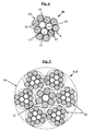
- FIG. 1 schematically, in section perpendicular to the axis of the strand (assumed to be rectilinear and at rest), an example of a preferential strand usable in the multistrand cable of the invention, having the construction 3 + 9.
- this type of construction has the consequence that the wires are arranged in two adjacent and concentric, tubular layers (C1 and C2), giving the strand (and its two layers) an outer contour E (shown in dotted lines) which is cylindrical and non-polygonal.
- the filling rubber extends continuously around the inner layer (C1) it covers.
- each of the J strands of the core, J varying from 1 to 4 is itself constituted by a two-layer construction cable.
- L + M which, in addition, preferably satisfies the characteristics of the K external strands which have been previously described.
- each of the J strands of the core (J varying from 1 to 4) has a construction identical to that of the K outer strands. But the invention also applies to cases where each of the J strands has a construction different from that of K external strands.
- the multistrand cable of the invention comprises a total of 6 strands, a central strand forming the core or inner layer (Ci) and 5 outer strands forming the outer layer (Ce), said cable having for example for more particular construction 1x (1 + 6) + 5 x (3 + 9).
- the multistrand cable of the invention comprises a total of 7 strands, a central strand forming the core or inner layer (Ci) and 6 outer strands forming the outer layer (Ce), said cable having for example for more particular constructions (1 + 6) x (1 + 6) or (1 + 6) x (3 + 9).
- FIG 2 schematically, in section perpendicular to the axis of the cable (assumed also rectilinear and at rest), a preferred example of such a cable multitorons (denoted C-1) according to the invention, having for construction 1 + 6 x (3 +9) or, according to equivalent nomenclature 1x (3 + 9) + 6x (3 + 9).
- This multistrand cable of the invention thanks to the in situ scrubbing of its individual strands, shows a strong penetration by the filling rubber (14), which gives it an improved endurance vis-à-vis the fatigue- corrosion.
- the multistrand cable of the invention comprises a total of 8 strands, a central strand forming the core or inner layer (Ci) and 7 outer strands forming the outer layer (Ce), said cable having for example for more particular constructions 1x (3 + 9) + 7x (1 + 6).
- the multistrand cable of the invention comprises a total of 9 strands, a central strand forming the core or inner layer (Ci) and 8 outer strands forming the outer layer (Ce), said cable having for example for more particular constructions 1x (3 + 9) + 8x (1 + 6) or 1x (4 + 10) + 8 x (1 + 6).
- the multistrand cable of the invention comprises a total of 10 strands, a central strand forming the core or inner layer (Ci) and 9 outer strands forming the outer layer (Ce), said cable having for example for more particular constructions 1x (3 + 9) + 9x (1 + 6) or 1x (4 + 10) + 9 x (1 + 6).
- the multistrand cable of the invention comprises a total of 11 strands, 3 central strands forming the core or inner layer (Ci) and 8 outer strands forming the outer layer (Ce), said cable having for example for more particular constructions 3x (1 + 6) + 8x (1 + 6) or 3x (3 + 9) + 8 x (3 + 9).
- the multistrand cable of the invention comprises a total of 12 strands, three central strands forming the core or inner layer (Ci) and 9 outer strands forming the outer layer (Ce), said cable having for example for more particular constructions (3 + 9) x (1 + 6) or (3 + 9) x (3 + 9).
- the multistrand cable of the invention comprises a total of 13 strands, 4 central strands forming the core or inner layer (Ci) and 9 outer strands forming the outer layer (Ce), said cable having for example for more particular constructions 4x (1 + 6) + 9x (1 + 6) or 4x (3 + 9) + 9x (3 + 9).
- the multistrand cable of the invention comprises a total of 14 strands, three central strands forming the core or inner layer (Ci) and 11 outer strands forming the outer layer (Ce), said cable having for example for more particular construction 3x (3 + 9) + 11 x (1 + 6).
- the multistrand cable of the invention comprises a total of 15 strands, three central strands forming the core or inner layer (Ci) and 12 outer strands forming the outer layer (Ce), said cable having for example for more particular construction 3x (3 + 9) + 12 x (1 + 6).
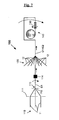
- the multistrand cable of the invention can, according to a particularly preferred embodiment of the invention, comprise a core (for recall, constituted by the (s) J strand (s), J varying from 1 to 4) which is it - Even sheathed by filling gum in the uncured state, this filling gum having identical or different formulation to that used for in situ scrubbing external strands. It suffices for that, as has been illustrated schematically in the figure 7 for the outer strands constituting the cable of the invention, to pass the core or inner layer (Ci) of the multistrand cable through an extrusion head of appropriate dimensions, before implementation by wiring the outer layer (Ce ) K external strands.
- FIG 3 schematically, in section perpendicular to the axis of the multistrand cable (assumed to be rectilinear and at rest), an example of a multitoron cable (denoted C-2) according to the invention, having for construction 1 + 6 x (3 + 9 ) in which the single central strand (3 + 9) forming its inner layer Ci was previously sheathed itself by filling rubber (16) before wiring the 6 outer strands (3 + 9) around the central strand and sheathed , for forming the cylindrical outer layer Ce. It is noted that the 7 external strands (10) constituting this cable C-2 are themselves gummed in situ by the filling rubber (14).
- This multistrand cable of the invention thanks in a way to a "double" in situ scrub, that of the individual strands during their prior manufacture and his own during his cabling, there is seen a penetration by the filling rubber (14, 16) which is further improved, which is the indicator recognized by those skilled in the art of excellent endurance vis-à-vis the fatigue- corrosion.
- the filling gum (16) used for the core sheathing (consisting of J center strands, J ranging from 1 to 4) of the multistrand cable of the invention may have a formulation identical to or different from the formulation of the gum filler (14) used for in situ scrubbing of K outer strands.
- the multistrand cables of the invention can be of two types, namely of the compact type or more preferably of the type with cylindrical layers. They may or may not be provided with an outer hoop constituted by a unitary fine wire helically wound around the outer K strands, in a direction (S or Z) identical to or opposite to that of said outer strands.
- FIG 4 schematically, in section perpendicular to the axis of the strand (assumed rectilinear and at rest), another example of a preferred strand for use in the multitoron cable of the invention, having the construction 3 + 9.
- This strand (20) is of compact type, that is to say that the son (21, 22) of its inner and outer layers (C1, C2) are wound at the same pitch (p 1 equal to p 2 ) and in the same direction (S / S or Z / Z).
- This type of construction has the result that the son are arranged in two layers (C1 and C2) adjacent and concentric giving the strand (and its two layers) an outer contour E (shown in dashed lines) which is polygonal and non-cylindrical.
- FIG. 5 schematically, in section perpendicular to the axis of the cable (also assumed rectilinear and at rest), another preferred example of a multitoron cable (denoted C-3) according to the invention, having for construction 1x (1 + 6) + 6x (3 + 9).
- each of the 6 outer strands has the same construction (3 + 9) corresponding to the strand (20) previously described in FIG. figure 4 .
- the central strand forming the core of the multistrand cable of the invention is of different construction (1 + 6).
- This multistrand cable of the invention thanks to the in situ scrubbing of all its individual strands, shows a strong penetration by the filling rubber (24), which gives it a high endurance vis-à-vis the fatigue-corrosion.
- the figure 6 schematizes another example of a multitoron cable (denoted C-4) according to the invention, whose construction 1x (1 + 6) + 6x (3 + 9), identical to that of the cable C-3 previous, but in which the single central strand (1 + 6) forming its inner layer Ci has previously been sheathed itself by filling rubber (26) before wiring the 6 outer strands (3 + 9) around the central strand thus sheathed, for formation of the cylindrical outer layer Ce; the 6 outer strands (10) constituting this cable C-4 are gummed in situ by the filling rubber (14).
- the strands of the inner layer Ci are preferably wound (in a helical pitch P J ) in the same direction of twist, that is to say in the direction S (final disposition "S / S"), or in the Z direction (final disposition "Z / Z”), as those of the outer layer Ce.
- the winding in the same direction of the layers Ci and Ce advantageously makes it possible to minimize the friction between these two layers and therefore the wear of the elementary strands which constitute them.
- the two layers are wound in the same direction (S / S or Z / Z) and at a different pitch (with preferentially P J ⁇ P K ), to obtain a multilayer cable of the layer type.
- cylindrical as represented for example in figures 2 and 3 .
- the pitch P J is between 15 and 45 mm, more preferably between 20 and 40 mm.
- the invention of course relates to multitoron cables previously described both in the green state (their filling rubber then being uncured) than in the cooked state (their filling rubber then being vulcanized).
- the multistrand cable of the invention with a filling gum in the green state until it is subsequently incorporated into the semi-finished product or finished product such as the tire for which it is intended, so as to favor the connection during the final vulcanization between the filling rubber and the surrounding rubber matrix (for example the calendering rubber).
- wire or wire is meant by definition in the present application a cable or strand formed of son constituted mainly (that is to say for more than 50% by number of these son) or integrally (for 100% son ) of a metallic material.
- the wires are preferably made of steel, more preferably of carbon steel. But it is of course possible to use other steels, for example a stainless steel, or other alloys.
- carbon steel When carbon steel is used, its carbon content (% by weight of steel) is preferably between 0.4% and 1.2%, especially between 0.5% and 1.1%; these levels represent a good compromise between the mechanical properties required for the tire and the feasibility of the wires. It should be noted that a carbon content of between 0.5% and 0.6% makes such steels ultimately less expensive because easier to draw.
- Another advantageous embodiment of the invention may also consist, depending on the applications concerned, of using steels with a low carbon content, for example between 0.2% and 0.5%, in particular because of a cost lower and easier to draw.
- the metal or steel used may itself be coated with a metal layer improving for example the properties of implementation of the wire rope and / or its constituent elements, or the properties of use of the cable and / or the tire themselves, such as adhesion properties, corrosion resistance or resistance to aging.
- the steel used is covered with a layer of brass (Zn-Cu alloy) or zinc; it is recalled that during the wire manufacturing process, the coating of brass or zinc facilitates the drawing of the wire, as well as the bonding of the wire with the rubber.
- the son could be covered with a thin metal layer other than brass or zinc, for example having the function of improving the resistance to corrosion of these son and / or their adhesion to rubber, for example a thin layer of Co, Ni, Al, an alloy of two or more compounds Cu, Zn, Al, Ni, Co, Sn.
- a thin metal layer other than brass or zinc for example having the function of improving the resistance to corrosion of these son and / or their adhesion to rubber, for example a thin layer of Co, Ni, Al, an alloy of two or more compounds Cu, Zn, Al, Ni, Co, Sn.
- the strands used in the multistrand cable of the invention are preferably made of carbon steel and have a tensile strength (Rm) preferably greater than 2500 MPa, more preferably greater than 3000 MPa.
- Rm tensile strength
- the total elongation at break (denoted At) of each constituent strand of the cable of the invention, the sum of its structural, elastic and plastic elongations, is preferably greater than 2.0%, more preferably at least 2, 5%.
- the elastomer (or indistinctly "rubber”, both of which are considered synonymous) of the filling compound is preferably a diene elastomer, chosen more preferentially from the group consisting of polybutadienes (BR), natural rubber (NR), synthetic polyisoprenes (IRs), the various copolymers of butadiene, the various isoprene copolymers, and mixtures of these elastomers.
- BR polybutadienes
- NR natural rubber
- IRs synthetic polyisoprenes
- Such copolymers are more preferably chosen from the group consisting of butadiene-styrene copolymers (SBR), the latter being prepared by emulsion polymerization (ESBR) as in solution (SSBR), the isoprene-butadiene copolymers (BIR ), isoprene-styrene copolymers (SIR) and isoprene-butadiene-styrene copolymers (SBIR).
- SBR butadiene-styrene copolymers
- ESBR emulsion polymerization
- SBIR isoprene-butadiene copolymers
- SIR isoprene-styrene copolymers
- SBIR isoprene-butadiene-styrene copolymers
- a preferred embodiment consists in using an "isoprene" elastomer, that is to say a homopolymer or a copolymer of isoprene, in other words a diene elastomer chosen from the group consisting of natural rubber (NR). , the synthetic polyisoprenes (IR), the various isoprene copolymers and the mixtures of these elastomers.
- the isoprene elastomer is preferably natural rubber or synthetic polyisoprene of the cis-1,4 type.
- polyisoprenes having a content (mol%) of cis-1,4 bonds greater than 90%, more preferably still greater than 98%, are preferably used.
- the diene elastomer may consist, in whole or in part, of another diene elastomer such as, for example, an SBR elastomer used in or with another elastomer, for example type BR.
- the filling rubber may contain one or more elastomer (s), in particular diene (s), which may be used in combination with any type of synthetic elastomer other than diene, or even with polymers other than elastomers.
- elastomer in particular diene (s)
- diene diene
- the filling rubber is preferably of the crosslinkable type, that is to say that it comprises by definition a crosslinking system adapted to allow the crosslinking of the composition during its baking (i.e., its hardening and not its melting); thus, in such a case, this rubber composition can be described as infusible, since it can not be melted by heating at any temperature.
- the system for crosslinking the rubber sheath is a so-called vulcanization system, that is to say based on sulfur (or a sulfur-donor agent). ) and at least one vulcanization accelerator. To this basic vulcanization system may be added various known vulcanization activators.
- Sulfur is used at a preferential rate of between 0.5 and 10 phr, more preferably between 1 and 8 phr
- the vulcanization accelerator for example a sulphenamide
- pce is used at a preferential rate of between 0.5 and 10.
- the invention also applies to cases where the filling compound is free from sulfur and even from any other crosslinking system, it being understood that the crosslinking or vulcanization system which is present in the crosslinking system may be sufficient for its own crosslinking.
- the filling rubber may also comprise, in addition to said crosslinking system, all or part of the additives normally used in rubber matrices intended for the manufacture of tires, such as, for example, reinforcing fillers such as carbon black or inorganic fillers such as silica, coupling agents, anti-aging agents, antioxidants, plasticizing agents or extension oils, whether the latter are of aromatic or non-aromatic nature, especially very low or non-aromatic oils, for example of naphthenic or paraffinic type, high or preferably low viscosity, MES or TDAE oils, plasticizing resins with high Tg greater than 30 ° C, agents facilitating the implementation (processability) of compositions in the raw state , tackifying resins, anti-eversion agents, methylene acceptors and donors such as, for example, HMT (hexamethylenethane) alumina) or H3M (hexamethoxymethylmelamine), reinforcing resins (such as resorcinol or bismaleimide), known adh
- the level of reinforcing filler is preferably greater than 50 phr, for example between 60 and 140 phr. It is more preferably greater than 70 phr, for example between 70 and 120 phr.
- carbon blacks for example, all carbon blacks are suitable, in particular blacks of the HAF, ISAF, SAF type conventionally used in tires (so-called pneumatic grade blacks). Among the latter, mention will be made more particularly of carbon blacks of (ASTM) grade 300, 600 or 700 (for example N326, N330, N347, N375, N683, N772).
- reinforcing inorganic fillers are especially suitable mineral fillers of the silica (SiO 2 ) type, in particular precipitated or fumed silica having a BET surface area of less than 450 m 2 / g, preferably from 30 to 400 m 2 / g.
- the formulation of the filling rubber can be chosen to be identical to the formulation of the rubber matrix that the cable of the invention is intended to reinforce; thus, there is no problem of compatibility between the respective materials of the filling rubber and said rubber matrix.
- the formulation of the filling gum may be chosen different from the formulation of the rubber matrix that the cable of the invention is intended to reinforce.
- the formulation of the filling gum may be adjusted by using a relatively high quantity of adhesion promoter, typically for example from 5 to 15 phr of a metal salt such as a cobalt salt, a nickel salt or a neodymium salt, and advantageously reducing the amount of said promoter (or even removing it completely) in the surrounding rubber matrix.
- the filling rubber has, in the crosslinked state, a secant modulus in extension E10 (at 10% elongation) which is between 5 and 25 MPa, more preferably between 5 and 20 MPa, in particular included in a range of 7 to 15 MPa.
- a secant modulus in extension E10 at 10% elongation
- the strands used in the multitoron cable of the invention described above could be optionally gummed in situ with a filling rubber based on elastomers other than diene, especially thermoplastic elastomers (TPE) such as for example polyurethane elastomers (TPU) not requiring a known manner of crosslinking or vulcanization but which have, at the operating temperature, properties similar to those of a vulcanized diene elastomer.
- TPE thermoplastic elastomers
- TPU polyurethane elastomers
- the present invention is implemented with a filling rubber based on diene elastomers such as previously described, thanks in particular to a specific manufacturing process which is particularly suitable for such elastomers; this manufacturing process is described in detail below.
- An essential feature of the above method is to use, both for the assembly of the inner layer C1 and that of the outer layer C2, a twisting step.
- L is the single core wire which undergoes the step of sheathing the filling rubber in the green state, before assembling by twisting the M outer layer wires (C2 ) around the core wire and sheathed.
- the L core wires are twisted together (direction S or Z) to form the inner layer C1, in a manner known per se; the son are delivered by feeding means such as coils, a distribution grid, coupled or not to a connecting grain, intended to converge the core son in a common point of torsion (or point of assembly).
- the inner layer (C1) thus formed is then sheathed with filling gum in the green state, provided by an extrusion screw at an appropriate temperature.
- the filling rubber can thus be delivered at a fixed point, unique and compact, by means of a single extrusion head, without using an individual sheathing son upstream of the assembly operations, before forming the inner layer, as described in the prior art.
- This method has the significant advantage of not slowing down the conventional assembly process. It makes the complete initial twisting, scrubbing and final twisting operation possible in one single step, irrespective of the type of strand produced (compact strand as cylindrical strand strand), all at high speed.
- the above process can be put implemented at a speed (speed of travel of the strand on the line of twisting-scrubbing) greater than 70 m / min, preferably greater than 100 m / min.
- the tension exerted on the L or yarn (s), substantially identical from one thread to another is preferably between 10 and 25% of the breaking force of the son.
- the extrusion head may comprise one or more dies, for example an upstream guide die and a downstream die calibration. It is possible to add continuous measurement and control means of the diameter of the strand connected to the extruder.
- the extrusion temperature of the filling rubber is between 60 ° C and 120 ° C, more preferably between 70 ° C and 110 ° C.
- the extrusion head thus defines a cladding zone having the shape of a cylinder of revolution whose diameter is for example between 0.4 mm and 1.2 mm, and whose length is for example between 4 and 10. mm.
- the amount of filling gum delivered by the extrusion head can be adjusted easily so that, in the final L + M strand, this amount is between 5 and 40 mg, preferably between 5 and 35 mg, especially in a range of 10 to 30 mg per g of strand.
- the inner layer C1 at any point of its periphery, is covered with a minimum thickness of filling gum which is preferably greater than 5 ⁇ m, more preferably greater than 10 ⁇ m, by example between 10 and 50 microns.
- the final assembly is carried out, always by twisting (direction S or Z), M threads of the outer layer (C2) around the inner layer (C1) and sheathed.
- twisting direction S or Z
- M threads of the outer layer (C2) around the inner layer (C1) and sheathed are arranged in the latter.
- the filling rubber moving under the pressure exerted by these external threads, then naturally tends to fill, at least in part, each of the interstices or cavities left empty by the threads, between the inner layer (C1) and the layer external (C2).
- the L + M strand is not yet finished: its central channel in particular, delimited by the 3 or 4 core wires when L is different from 1 or 2, is not yet filled with gum. filling, in any case insufficiently to obtain an impermeability to air that is acceptable.
- the next important step is to pass the strand, thus provided with its filling rubber in the green state, through torsion balancing means to obtain a said cable balanced in torsion (that is to say virtually without residual torsion);
- Torsional balancing here means, in a manner well known to those skilled in the art, the cancellation of the residual torsion torques (or of the springback of untwisting) exerted on each strand wire, in the inner layer as in the outer layer.
- Torsion balancing tools are known to those skilled in the art of twisting; they may consist for example of "trainers” and / or “twisters” and / or “twister-trainers” consisting of either pulleys for twisters or small diameter rollers for trainers, pulleys or rollers through which circulates the strand in a single plane or preferably in at least two different planes.
- the process described above exploits the rotation of the corewires, at the final stage of manufacture of the strand, in order to distribute, naturally, the filling rubber inside and around the inner layer (C1), while perfectly controlling the amount of filling compound provided.
- Those skilled in the art will in particular be able to adjust the arrangement, the diameter of the pulleys and / or rollers of the torsion-balancing means, in order to vary the intensity of the radial pressure acting on the various wires.
- the manufacture of the outer strand, gummed in situ by its filling rubber in the green state, is complete.
- This strand is wound on one or more reception coils, for storage, before the operation subsequent wiring of the elementary strands to obtain the multi-conductor cable of the invention.
- This manufacturing method naturally applies to the manufacture of external strands of the compact type (for recall and by definition, those whose layers C1 and C2 are wound at the same pitch and in the same direction) as layer-type cables.
- cylindrical for recall and by definition, those whose layers C1 and C2 are wound either in different steps or in opposite directions, or in different steps and in opposite directions).
- FIG. figure 7 annexed an example of device (100) for assembly by twisting, of the type with rotating feed and receiving, usable for the manufacture of a strand of the type with cylindrical layers (not p 1 and p 2 different and / or different direction of torsion layers C1 and C2), for example of construction 3 + 9 as illustrated in FIG. figure 1 .
- supply means (110) deliver M (for example three) core wires (11) through a distribution grid (111) (axisymmetrical distributor), coupled or not with a grain of assembly (112), beyond which converge the M son (11) at an assembly point or twisting point (113) for forming the inner layer (C1).
- the inner layer C1 once formed, then passes through a cladding zone consisting for example of a single extrusion head (114) through which is intended to circulate the inner layer.
- the distance between the point of convergence (113) and the sheathing point (114) is for example between 50 cm and 1 m.
- the strand C1 + C2 thus formed is finally collected on a rotary reception (140), after passing through the torsion balancing means (130) consisting for example of a trainer or a twister-trainer.
- the multistrand cable of the invention For manufacturing the multistrand cable of the invention, one proceeds in a manner well known to those skilled in the art, by wiring or twisting the elementary strands previously obtained, using cabling or twisting machines sized to assemble strands.
- the J strands (J ranging from 2 to 4) constituting the core of the cable of the invention are preferably assembled by wiring.
- the core of the multistrand cable of the invention may itself be sheathed by a filling rubber whose formulation may be identical to or different from the formulation of the gum. filling used for in situ scrubbing of K outer strands.
- the multistrand cable of the invention can be used for reinforcing articles other than tires, for example pipes, belts, conveyor belts; advantageously, it could also be used for reinforcing parts of tires other than their crown reinforcement, in particular for reinforcing the carcass reinforcement of tires for industrial vehicles.
- the cable of the invention is particularly intended for a tire crown reinforcement for large industrial vehicles such as civil engineering, including mining type.
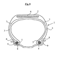
- the figure 8 very schematically represents a radial section of a metal crown reinforcement tire which may or may not be in conformity with the invention, in this general representation.
- This tire 1 has a crown 2 reinforced by a crown reinforcement or belt 6, two sidewalls 3 and two beads 4, each of these beads 4 being reinforced with a rod 5.
- the crown 2 is surmounted by a tread not shown in this schematic figure.
- a carcass reinforcement 7 is wound around the two rods 5 in each bead 4, the upturn 8 of this armature 7 being for example disposed towards the outside of the tire 1 which is shown here mounted on its rim 9.
- the carcass reinforcement 7 is in known manner constituted by at least one sheet reinforced by so-called "radial” cables, that is to say that these cables are arranged substantially parallel to each other and extend from a bead to the other so as to form an angle of between 80 ° and 90 ° with the median circumferential plane (plane perpendicular to the axis of rotation of the tire which is located halfway between the two beads 4 and passes through the middle of the crown frame 6).
- the tire according to the invention is characterized in that its belt 6 comprises at least, as reinforcement of at least one of the belt plies, a multitoron cable according to the invention.
- this belt 6 schematically in a very simple way on the figure 7
- the multistrand cables of the invention may, for example, reinforce all or part of the so-called working belt plies.
- this tire 1 also comprises, in a known manner, an inner rubber or elastomer layer (commonly called "inner rubber”) which defines the radially inner face of the tire and which is intended to protect the carcass ply from the diffusion of the tire. air from the interior space to the tire.
- the carbon steel wires are prepared in a known manner, for example starting from machine wires (diameter 5 to 6 mm) which are first cold-rolled, by rolling and / or drawing, to a neighboring intermediate diameter. of 1 mm.
- the steel used for the cable C-1 according to the invention is a carbon steel of the very high strength type (called SHT for " Super High Tensile ”) whose carbon content is about 0.92%, comprising About 0.2% chromium, the balance being iron and the usual unavoidable impurities associated with the steelmaking process.
- SHT very high strength type
- the intermediate diameter son undergo a degreasing treatment and / or pickling, before further processing.
- a degreasing treatment and / or pickling After deposition of a brass coating on these intermediate son, is carried on each wire a so-called “final” work hardening (ie, after the last patenting heat treatment), by cold drawing in a moist medium with a drawing lubricant which is for example in the form of an aqueous emulsion or dispersion.
- the steel wires thus drawn have the following diameter and mechanical properties: ⁇ b> Table 1 ⁇ / b> Steel ⁇ (mm) Fm (N) Rm (MPa) SHT 0.30 226 3200
- wires are then assembled in the form of strands with two layers of construction 3 + 9 (referenced 10 at the Fig. 1 ) and whose mechanical properties, measured on strands extracted from a multitoron cable according to the invention (of construction (1 + 6) x (3 + 9) with a pitch P K equal to 40 mm, as schematized in FIG. the Fig. 2 ), are given in Table 2: ⁇ b> Table 2 ⁇ / b> Strand p 1 (mm) p 2 (mm) Fm (daN) Rm (MPa) 3 + 9 7.5 15.0 256 3040
- This strand 3 + 9 (10), as schematized at Fig. 1 , is formed of 12 wires in total, all of diameter 0.30 mm, which have been wound at different steps and in the same direction of twist (S / S) for obtaining a strand of the type with cylindrical layers.
- the level of filling gum, measured according to the method indicated previously in paragraph I-3, is 22 mg per g of strand.
- the filling rubber is a conventional rubber composition for tire crown reinforcement. This composition was extruded at a temperature of 90 ° C. through a calibration die of 0.700 mm.
- the previously manufactured strands (3 + 9) were furthermore subjected to the air permeability test described in paragraph I-2, to strand lengths of 4 cm (equal to P K ), by measuring the volume of air (in cm 3 ) passing through the strands in 1 minute (average of 10 measurements for each strand tested).
- a flow rate of zero or less than 0.2 cm 3 / min was measured; in other words, the strands of the cables of the invention can be described as airtight along their axis; they therefore have an optimal penetration rate by rubber.
- control in situ gummed strands of the same construction as the preceding strands (10), were prepared by individually sheathing either a single wire or each of the three wires of the inner layer C1. This sheathing was carried out using extrusion dies of variable diameter (320 to 410 ⁇ m) arranged this time upstream of the assembly point (sheathing and in-line twisting) as described in the prior art (according to request supra US 2002/160213 ); for a rigorous comparison, the amount of filling gum was adjusted in such a way that the level of filling gum in the final strands (between 5 and 30 mg / g of strand, measured according to the method of the paragraph I-3), which is close to that of the strands of the multistrand cable of the invention.
- the multistrand cable of the invention is able to have improved fatigue and fatigue-corrosion endurance, while satisfying the usual wiring and scrubbing requirements in industrial conditions.
Claims (15)
- Mehrlitziges Metallseil (C-1) mit zwei Lagen (Ci, Ce) mit J+K-Aufbau, das aus einer Seele besteht, die J Litzen umfasst, die eine Innenlage (Ci) bilden, wobei J von 1 bis 4 variiert, wobei K Außenlitzen um die Seele herum schraubenförmig gemäß einer Schraubensteigung PK gewickelt sind, wobei die Außenlitzen eine Außenlage (Ce) um die Innenlage (Ci) herum bilden, wobei jede Außenlitze:- aus einem Seil mit zwei Schichten (C1, C2) mit L+M-Aufbau besteht, das vor Ort gummiert wird und eine Innenlage (C1), die aus L Drähten mit einem Durchmesser d1 besteht, wobei L von 1 bis 4 variiert, und eine Außenlage (C2) mit M Drähten, wobei M größer gleich 5 ist, mit einem Durchmesser d2 umfasst, die zusammen schraubenförmig gemäß einer Steigung p2 um die Innenlage (C1) gewickelt sind; wobei seine Innenlage (C1) durch eine "Füllgummi" genannte Kautschukzusammensetzung ummantelt ist; wobei jede Außenlitze die folgenden Charakteristika aufweist (d1, d2 sind in mm ausgedrückt) :dadurch gekennzeichnet, dass jede Außenlitze die folgenden Charakteristika aufweist (p2 ist in mm ausgedrückt) :∘ 0,10 < d1 < 0,50 ;∘ 0,10 < d2 < 0,50,- 6 < p2 < 30;- das Füllgummi über jegliche Länge einer Außenlitze, die gleich PK ist, in jeder der Kapillaren, die von den L Drähten der Innenlage (C1) und den M Drähten der Außenlage (C2) begrenzt werden, sowie, wenn L gleich 3 oder 4 ist, in dem zentralen Kanal vorliegt, der von den L Drähten der Innenlage (C1) begrenzt wird;- der Füllgummigehalt in der Außenlitze zwischen 5 und 40 mg pro g Litze liegt;- jede Außenlitze in ihrem Umfang frei von Füllgummi ist;und dass PK zwischen 20 und 70 mm liegt.
- Seil nach Anspruch 1, wobei in jeder Außenlitze die folgenden Charakteristika erfüllt sind:- 0,15 < d1 < 0,35;- 0,15 < d2 < 0,35.
- Seil nach Anspruch 1 oder 2, wobei in jeder Außenlitze p2 in einem Bereich von 12 bis 25 mm liegt.
- Seil nach einem der Ansprüche 1 bis 3, wobei PK in einem Bereich von 25 bis 60 mm, vorzugsweise 30 bis 50 mm liegt.
- Seil nach einem der Ansprüche 1 bis 4, wobei PK das folgende Verhältnis erfüllt:

- Seil nach Anspruch 5, wobei in jeder Außenlitze L gleich 1 ist und M gleich 5, 6 oder 7 ist.
- Seil nach einem der Ansprüche 1 bis 5, wobei in jeder Außenlitze L sich von 1 unterscheidet und die L Drähte mit dem Durchmesser d1 schraubenförmig gemäß einer Steigung p1 gewickelt sind, wobei die folgenden Verhältnisse erfüllt sind:


- Seil nach Anspruch 7, wobei in jeder Außenlitze p1 in einem Bereich von 6 bis 30 mm, vorzugsweise 6 bis 25 mm liegt.
- Seil nach Anspruch 7 oder 8, wobei in jeder Außenlitze p1 gleich p2 ist.
- Seil nach einem der Ansprüche 1 bis 9, wobei in jeder Außenlitze die Außenlage eine gesättigte Lage ist.
- Seil nach einem der Ansprüche 1 bis 10, wobei in jeder Außenlitze der Kautschuk des Füllgummis vorzugsweise ein Dienkautschuk ist, der aus der Gruppe bestehend aus Polybutadienen, Naturkautschuk, synthetischen Polyisoprenen, Butadiencopolymeren, Isoprencopolymeren und Gemischen dieser Elastomere ausgewählt ist.
- Seil nach einem der Ansprüche 1 bis 11, dadurch gekennzeichnet, dass im Luftdurchlässigkeitstest gemäß Absatz I-2 jede Außenlitze einen mittleren Luftdurchsatz von weniger als 2 cm3/min, vorzugsweise weniger oder höchstens gleich 0,2 cm3/min aufweist.
- Seil nach einem der Ansprüche 1 bis 12, wobei jede von J Litzen der Seele, wobei J von 1 bis 4 variiert, selbst aus einem Seil mit zwei Lagen mit L+M-Aufbau, das die Charakteristika von K Außenlitzen erfüllt, nach einem der Ansprüche 1 bis 12 besteht.
- Seil nach einem der Ansprüche 1 bis 13, wobei die Seele des Seils, die aus den J Litzen besteht, wobei J von 1 bis 4 variiert, selbst durch das Füllgummi ummantelt ist.
- Reifen, der ein Seil nach einem der Ansprüche 1 bis 14 umfasst.
Applications Claiming Priority (2)
| Application Number | Priority Date | Filing Date | Title |
|---|---|---|---|
| FR0954592A FR2947574B1 (fr) | 2009-07-03 | 2009-07-03 | Cable multitorons dont les torons elementaires sont des cables a deux couches gommes in situ. |
| PCT/EP2010/059524 WO2011000963A2 (fr) | 2009-07-03 | 2010-07-05 | Cable multitorons dont les torons elementaires sont des cables a deux couches gommes in situ |
Publications (2)
| Publication Number | Publication Date |
|---|---|
| EP2449171A2 EP2449171A2 (de) | 2012-05-09 |
| EP2449171B1 true EP2449171B1 (de) | 2015-09-09 |
Family
ID=41682663
Family Applications (1)
| Application Number | Title | Priority Date | Filing Date |
|---|---|---|---|
| EP10737302.9A Active EP2449171B1 (de) | 2009-07-03 | 2010-07-05 | Merhlitziges stahlkabel wobei die zweilagigen litzen mit kunststoff wàhrend der produktion versehen werden |
Country Status (9)
| Country | Link |
|---|---|
| US (1) | US8863490B2 (de) |
| EP (1) | EP2449171B1 (de) |
| JP (1) | JP5840608B2 (de) |
| KR (1) | KR101651714B1 (de) |
| CN (1) | CN102471998B (de) |
| BR (1) | BR112012000120A2 (de) |
| EA (1) | EA201270125A1 (de) |
| FR (1) | FR2947574B1 (de) |
| WO (1) | WO2011000963A2 (de) |
Families Citing this family (43)
| Publication number | Priority date | Publication date | Assignee | Title |
|---|---|---|---|---|
| FR2947575B1 (fr) * | 2009-07-03 | 2011-08-19 | Michelin Soc Tech | Cable multitorons dont les torons elementaires sont des cables a deux couches gommes in situ. |
| FR2947574B1 (fr) * | 2009-07-03 | 2012-11-09 | Michelin Soc Tech | Cable multitorons dont les torons elementaires sont des cables a deux couches gommes in situ. |
| FR2962454B1 (fr) * | 2010-05-20 | 2012-09-21 | Michelin Soc Tech | Procede de fabrication d'un cable metallique a trois couches du type gomme in situ |
| FR2962456B1 (fr) * | 2010-05-20 | 2012-09-21 | Michelin Soc Tech | Procede de fabrication d'un cable metallique multicouches gomme in situ par un elastomere thermoplastique insature |
| FR2950904A1 (fr) * | 2010-12-17 | 2011-04-08 | Michelin Soc Tech | Cable metallique multitorons a haute permeabilite. |
| US20130270043A1 (en) * | 2010-12-22 | 2013-10-17 | Otis Elevator Company | Elevator system belt |
| FR2975406B1 (fr) * | 2011-05-18 | 2014-10-17 | Michelin Soc Tech | Cordon composite caoutchouteux pour bande de roulement de bandage pneumatique |
| FR2982885B1 (fr) * | 2011-11-23 | 2014-11-07 | Michelin Soc Tech | Procede de fabrication d'un cable metallique a deux couches gomme in situ par un elastomere thermoplastique insature |
| FR2982884B1 (fr) * | 2011-11-23 | 2014-06-06 | Michelin Soc Tech | Cable metallique a deux couches, gomme in situ par un elastomere thermoplastique insature |
| CN104066883B (zh) | 2012-02-06 | 2017-09-15 | 贝卡尔特公司 | 包含三元或四元黄铜合金涂层的狭长钢元件及相应的制造方法 |
| EP2812480B1 (de) | 2012-02-06 | 2017-08-30 | NV Bekaert SA | Längliches stahlelement mit einer beschichtung aus einer ternären oder quaternären messinglegierung und zugehöriges verfahren |
| FR2990962B1 (fr) * | 2012-05-25 | 2014-06-27 | Michelin & Cie | Procede de fabrication d'un cable metallique multi-torons a deux couches. |
| FR2990963B1 (fr) * | 2012-05-25 | 2014-12-05 | Michelin & Cie | Cable metallique multi-torons a deux couches. |
| KR102077359B1 (ko) * | 2012-07-24 | 2020-02-13 | 엔브이 베카에르트 에스에이 | 황동이 선택적으로 코팅된 필라멘트를 갖는 고무 강화재용 강철 코드 |
| FR2996230B1 (fr) * | 2012-09-28 | 2014-10-31 | Michelin & Cie | Cable gomme in situ comprenant une composition comprenant un polysulfure organique. |
| FR2997410B1 (fr) | 2012-10-30 | 2016-01-01 | Michelin & Cie | Cable gomme in situ comprenant une composition comprenant un copolymere de styrene-butadiene. |
| JP6063768B2 (ja) * | 2013-02-21 | 2017-01-18 | 住友ゴム工業株式会社 | スチールコード及びそれを用いた弾性クローラ |
| FR3022263B1 (fr) * | 2014-06-12 | 2017-10-27 | Michelin & Cie | Cable gomme in situ comprenant une composition de gommage comprenant un inhibiteur de corrosion |
| FR3022262B1 (fr) * | 2014-06-12 | 2016-06-03 | Michelin & Cie | Cable gomme in situ comprenant une composition de gommage comprenant un inhibiteur de corrosion |
| FR3022265B1 (fr) * | 2014-06-12 | 2017-12-08 | Michelin & Cie | Produit semi-fini comprenant un cable gomme in situ noye dans une composition de caoutchouc de calandrage |
| FR3022264A1 (fr) | 2014-06-12 | 2015-12-18 | Michelin & Cie | Produit semi-fini comprenant un cable gomme in situ noye dans une composition de caoutchouc de calandrage |
| FR3022261B1 (fr) * | 2014-06-12 | 2016-06-03 | Michelin & Cie | Cable gomme in situ comprenant une composition de gommage comprenant un inhibiteur de corrosion |
| DE102014211929A1 (de) * | 2014-06-23 | 2016-01-07 | ContiTech Transportsysteme GmbH | Verfahren zur Herstellung eines Zugträgers in Seilkonstruktion, insbesondere für Fördergurte |
| JP5811240B1 (ja) * | 2014-06-30 | 2015-11-11 | 横浜ゴム株式会社 | スチールコードおよびコンベヤベルト |
| JP6545942B2 (ja) * | 2014-10-01 | 2019-07-17 | 株式会社ブリヂストン | ゴム物品補強用スチールコードおよびそれを用いた空気入りタイヤ |
| WO2018004487A1 (en) * | 2016-07-01 | 2018-01-04 | Kordsa Teknik Tekstil Anonim Sirketi | Novel bielastic polyester tire cord as cap ply |
| JP6717701B2 (ja) | 2016-08-05 | 2020-07-01 | 株式会社ブリヂストン | タイヤ用スチールコードおよびこれを用いた空気入りタイヤ |
| CN107953728B (zh) * | 2017-11-27 | 2020-02-11 | 江苏兴达钢帘线股份有限公司 | 一种缆型胎圈及轮胎 |
| JP7330191B2 (ja) * | 2017-12-19 | 2023-08-21 | コンパニー ゼネラール デ エタブリッスマン ミシュラン | 超低、低、及び中程度の弾性率を有する2層マルチストランドコード |
| EP3728728B1 (de) | 2017-12-19 | 2022-07-20 | Compagnie Generale Des Etablissements Michelin | Zweilagige mehrsträngige korde mit sehr niedrigen, niedrigen und mittleren moduli |
| US11346049B2 (en) | 2017-12-19 | 2022-05-31 | Compagnie Generale Des Etablissements Michelin | Two-layer multi-strand cords having very low, low and medium moduli |
| US11591750B2 (en) | 2017-12-19 | 2023-02-28 | Compagnie Generale Des Etablissements Michelin | Two-layer multi-strand cables having very low, low and medium modulus |
| JP7309715B2 (ja) | 2017-12-19 | 2023-07-18 | コンパニー ゼネラール デ エタブリッスマン ミシュラン | 超低、低、及び中程度の弾性率を有する2層マルチストランドコード |
| JOP20200181A1 (ar) * | 2018-01-24 | 2022-10-30 | Ctc Global Corp | ترتيب نهائي لكابل كهربائي علوي |
| AU2019291195A1 (en) * | 2018-06-20 | 2021-01-21 | Compagnie Generale Des Etablissements Michelin | Double-layer multi-strand cord with improved penetrability |
| JP7278745B2 (ja) * | 2018-10-30 | 2023-05-22 | 株式会社ブリヂストン | エラストマー補強用コード |
| JP7278744B2 (ja) * | 2018-10-30 | 2023-05-22 | 株式会社ブリヂストン | エラストマー補強用コード |
| FR3103201A1 (fr) * | 2019-11-15 | 2021-05-21 | Compagnie Generale Des Etablissements Michelin | Câble multi-torons à deux couches avec couche interne gainée à rendement amélioré |
| AU2020383800A1 (en) * | 2019-11-15 | 2022-05-19 | Compagnie Generale Des Etablissements Michelin | Two-layer multi-strand cable having a sheathed inner layer and improved penetrability |
| FR3103500A1 (fr) * | 2019-11-22 | 2021-05-28 | Compagnie Generale Des Etablissements Michelin | Câble multi-torons à deux couches à énergie de rupture surfacique améliorée |
| WO2021124154A1 (en) * | 2019-12-17 | 2021-06-24 | Pirelli Tyre S.P.A. | Metallic reinforcing cord for tyres for vehicle wheels |
| KR20220116335A (ko) * | 2020-01-07 | 2022-08-22 | 꽁빠니 제네날 드 에따블리세망 미쉘린 | 파단 에너지가 개선되고 총 연신율이 개선된 단층 다중 스트랜드 케이블 |
| CN117136262A (zh) * | 2020-11-02 | 2023-11-28 | Kv研发中心股份有限公司 | 绳缆、缆股、用于制造绳缆和缆股的方法和设备 |
Citations (1)
| Publication number | Priority date | Publication date | Assignee | Title |
|---|---|---|---|---|
| US5139874A (en) * | 1991-09-05 | 1992-08-18 | The Goodyear Tire & Rubber Company | Cable for reinforcing rubber articles |
Family Cites Families (44)
| Publication number | Priority date | Publication date | Assignee | Title |
|---|---|---|---|---|
| CA2109904C (en) * | 1992-12-18 | 2004-09-14 | Pol Bruyneel | Multi-strand steel cord |
| JP3179255B2 (ja) * | 1993-08-17 | 2001-06-25 | 株式会社ブリヂストン | ゴム物品補強用スチールコード |
| US6247514B1 (en) | 1994-12-20 | 2001-06-19 | The Goodyear Tire & Rubber Company | Tires with high strength reinforcement |
| DE19535597A1 (de) * | 1995-09-25 | 1997-03-27 | Drahtcord Saar Gmbh & Co Kg | Drahtseil zur Verstärkung von Gummiartikeln |
| ATE197972T1 (de) | 1995-10-27 | 2000-12-15 | Bekaert Sa Nv | Strahlseil mit mehreren litzen |
| GB2332454B (en) * | 1997-12-19 | 2000-02-16 | Bridon Plc | Rope for conveying systems |
| FR2795751A1 (fr) | 1999-06-29 | 2001-01-05 | Michelin Soc Tech | Cable d'acier multicouches pour carcasse de pneumatique |
| WO2001034900A1 (fr) * | 1999-11-11 | 2001-05-17 | Bridgestone Corporation | Cable d'acier de renforcement d'un article en caoutchouc et pneumatique correspondant |
| KR20020063611A (ko) | 1999-12-30 | 2002-08-03 | 소시에떼 드 테크놀로지 미쉐린 | 타이어 카캐스용 다층 강 케이블 |
| US6920745B2 (en) * | 2000-05-08 | 2005-07-26 | N.V. Bekaert S.A. | Zinc-coated steel cord with improved fatigue resistance |
| CN2432237Y (zh) * | 2000-08-04 | 2001-05-30 | 江苏兴达钢帘线股份有限公司 | 一种钢帘线 |
| KR100803644B1 (ko) * | 2000-09-11 | 2008-02-19 | 요코하마 고무 가부시키가이샤 | 타이어용 강철 코드 및 래디얼 타이어 |
| DE10213289A1 (de) * | 2001-03-30 | 2002-11-14 | Yokohama Rubber Co Ltd | Elastomer-und-Stahlkord-Verbundwerkstoff und Prozess zur Herstellung desselben |
| US7426821B2 (en) | 2002-07-17 | 2008-09-23 | Nv Bekaert Sa | Metal strand comprising interrupted filament |
| US6817395B2 (en) | 2002-07-30 | 2004-11-16 | The Goodyear Tire & Rubber Company | Crown reinforcement for heavy duty tires |
| FR2864556B1 (fr) * | 2003-12-24 | 2006-02-24 | Michelin Soc Tech | Cable a couches pour armature de carcasse de pneumatique |
| CN100589998C (zh) * | 2003-12-30 | 2010-02-17 | 倍耐力轮胎公司 | 用于车辆的轮胎 |
| FR2869618B1 (fr) | 2004-04-30 | 2008-10-10 | Michelin Soc Tech | Composition de caoutchouc a adhesion amelioree vis a vis d'un renfort metallique. |
| FR2870264B1 (fr) * | 2004-05-12 | 2006-07-14 | Michelin Soc Tech | Cable metallique pour pneumatique |
| FR2873721A1 (fr) | 2004-08-02 | 2006-02-03 | Michelin Soc Tech | Cable a couches pour armature de sommet de pneumatique |
| US7458200B2 (en) * | 2005-12-08 | 2008-12-02 | The Goodyear Tire & Rubber Co. | High elongation cable |
| US7775247B2 (en) | 2005-12-22 | 2010-08-17 | The Goodyear Tire & Rubber Company | Steel cord for reinforcement of off-the-road tires |
| FR2897076B1 (fr) * | 2006-02-09 | 2008-04-18 | Michelin Soc Tech | Cable composite elastique pour pneumatique. |
| EP2423380B1 (de) | 2006-08-31 | 2016-10-12 | Bridgestone Corporation | Stahlcord zur Verstärkung von Gummi- und Luftradialreifen |
| JP4963389B2 (ja) * | 2006-09-14 | 2012-06-27 | 株式会社ブリヂストン | スチールコード、ゴム−スチールコード複合体およびタイヤ |
| JP2009024268A (ja) * | 2007-07-17 | 2009-02-05 | Bridgestone Corp | ゴム物品補強用コードおよび空気入りタイヤ |
| WO2009011397A1 (ja) * | 2007-07-17 | 2009-01-22 | Bridgestone Corporation | コードおよびその製造方法並びに、コードおよびゴムの複合体 |
| BRPI0821562A2 (pt) * | 2007-12-21 | 2015-06-16 | Bekaert Sa Nv | Cordão de aço compreendendo um material de termocura de um componente curável com calor |
| FR2925923B1 (fr) * | 2007-12-28 | 2009-12-18 | Michelin Soc Tech | Procede et dispositif de fabrication d'un cable a deux couches du type gomme in situ |
| FR2925922B1 (fr) * | 2007-12-28 | 2009-12-18 | Soc Tech Michelin | Cable a couches pour ceinture de pneumatique |
| FR2934614B1 (fr) * | 2008-08-01 | 2010-09-10 | Michelin Soc Tech | Cable a couches gomme in situ pour armature carcasse de pneumatique. |
| JP5847990B2 (ja) * | 2008-11-14 | 2016-01-27 | 株式会社ブリヂストン | ゴム物品補強用スチールコードおよび空気入りタイヤ |
| FR2940184B1 (fr) * | 2008-12-22 | 2011-03-04 | Michelin Soc Tech | Pneumatique comportant des cables d'armature de carcasse presentant une faible permeabilite, et des fils textiles associes a l'armature de carcasse |
| FR2940183B1 (fr) * | 2008-12-22 | 2011-03-04 | Michelin Soc Tech | Pneumatique comportant des cables d'armature de carcasse presentant une faible permeabilite, et des fils textiles associes a l'armature de carcasse |
| JP5513002B2 (ja) * | 2009-04-20 | 2014-06-04 | 株式会社ブリヂストン | ゴム−スチールコード複合体および空気入りラジアルタイヤ |
| FR2947574B1 (fr) * | 2009-07-03 | 2012-11-09 | Michelin Soc Tech | Cable multitorons dont les torons elementaires sont des cables a deux couches gommes in situ. |
| FR2947575B1 (fr) * | 2009-07-03 | 2011-08-19 | Michelin Soc Tech | Cable multitorons dont les torons elementaires sont des cables a deux couches gommes in situ. |
| FR2954219A1 (fr) * | 2009-11-17 | 2011-06-24 | Michelin Soc Tech | Pneumatique comportant des cables d'armature de carcasse presentant des permeabilites differentes |
| FR2953450B1 (fr) * | 2009-12-04 | 2011-11-18 | Michelin Soc Tech | Pneumatique comportant des cables d'armature de carcasse presentant des permeabilites differentes |
| FR2953452B1 (fr) * | 2009-12-04 | 2011-12-09 | Michelin Soc Tech | Pneumatique comportant des cables d'armature de carcasse frettes |
| FR2959517B1 (fr) * | 2010-04-28 | 2012-09-21 | Michelin Soc Tech | Cable metallique multitorons elastique a haute permeabilite. |
| FR2969036B1 (fr) * | 2010-12-21 | 2012-12-28 | Michelin Soc Tech | Pneumatique dont l'armature de carcasse est renforcee par une couche d'elements de renforcement dans la zone du bourrelet |
| FR2969035B1 (fr) * | 2010-12-21 | 2014-08-29 | Michelin Soc Tech | Pneumatique dont l'armature de carcasse est renforcee par une couche d'elements de renforcement dans la zone du bourrelet |
| FR2969038B1 (fr) * | 2010-12-21 | 2012-12-28 | Michelin Soc Tech | Pneumatique dont l'armature de carcasse est renforcee par une couche d'elements de renforcement dans la zone du bourrelet |
-
2009
- 2009-07-03 FR FR0954592A patent/FR2947574B1/fr not_active Expired - Fee Related
-
2010
- 2010-07-05 WO PCT/EP2010/059524 patent/WO2011000963A2/fr active Application Filing
- 2010-07-05 EA EA201270125A patent/EA201270125A1/ru unknown
- 2010-07-05 US US13/382,150 patent/US8863490B2/en active Active
- 2010-07-05 JP JP2012518933A patent/JP5840608B2/ja active Active
- 2010-07-05 EP EP10737302.9A patent/EP2449171B1/de active Active
- 2010-07-05 CN CN201080029090.7A patent/CN102471998B/zh active Active
- 2010-07-05 BR BR112012000120A patent/BR112012000120A2/pt not_active IP Right Cessation
- 2010-07-05 KR KR1020127002901A patent/KR101651714B1/ko active IP Right Grant
Patent Citations (1)
| Publication number | Priority date | Publication date | Assignee | Title |
|---|---|---|---|---|
| US5139874A (en) * | 1991-09-05 | 1992-08-18 | The Goodyear Tire & Rubber Company | Cable for reinforcing rubber articles |
Also Published As
| Publication number | Publication date |
|---|---|
| EA201270125A1 (ru) | 2012-07-30 |
| FR2947574B1 (fr) | 2012-11-09 |
| KR101651714B1 (ko) | 2016-08-26 |
| EP2449171A2 (de) | 2012-05-09 |
| JP2012531540A (ja) | 2012-12-10 |
| CN102471998B (zh) | 2015-07-15 |
| CN102471998A (zh) | 2012-05-23 |
| KR20120049244A (ko) | 2012-05-16 |
| JP5840608B2 (ja) | 2016-01-06 |
| BR112012000120A2 (pt) | 2016-03-15 |
| WO2011000963A3 (fr) | 2011-03-03 |
| US8863490B2 (en) | 2014-10-21 |
| WO2011000963A2 (fr) | 2011-01-06 |
| FR2947574A1 (fr) | 2011-01-07 |
| US20120174557A1 (en) | 2012-07-12 |
Similar Documents
| Publication | Publication Date | Title |
|---|---|---|
| EP2449171B1 (de) | Merhlitziges stahlkabel wobei die zweilagigen litzen mit kunststoff wàhrend der produktion versehen werden | |
| EP2449170B1 (de) | Mehrlitziges verstärkungskabel, wobei die einzelnen litzen mit rohgummi bei deren schlagen versehen weren | |
| EP2238289B1 (de) | In-situ gummiertes schichtkabel für reifengürtel | |
| EP2366046B1 (de) | Mehrlagige drahtlitze mit während des schlagens eingebrachtem füller als verstärkung eines reifens | |
| EP2326765B1 (de) | In-situ-gummiertes schichtkabel zur karkassenverstärkung von reifen | |
| EP2366048B1 (de) | Verfahren und vorrichtung zur herstellung einer mehrlagigen litze als reifenverstärkung mit während des schlagens eingebrachten füller | |
| EP2414583B1 (de) | Verfahren und vorrichtung zur herstellung einer dreilagigen stahllitze | |
| EP2414582B1 (de) | Verfahren und vorrichtung zur herstellung einer dreilagigen stahllitze | |
| EP2238288B1 (de) | Verfahren und vorrichtung zur herstellung eines kabels mit zwei schichten der in-situ-verbindungstype | |
| FR2946366A1 (fr) | Cable a trois couches,gomme in situ,pour armature carcasse de pneumatique. | |
| EP2449168A2 (de) | In-situ gummiertes dreilagiges stahlseil mit 2+m+n-struktur | |
| EP2449169A2 (de) | In-situ gummiertes dreilagiges stahlseil mit 3+m+n-struktur | |
| EP2727744A1 (de) | Stahlseil mit mehreren Litzen für Luftreifen | |
| FR2950904A1 (fr) | Cable metallique multitorons a haute permeabilite. |
Legal Events
| Date | Code | Title | Description |
|---|---|---|---|
| PUAI | Public reference made under article 153(3) epc to a published international application that has entered the european phase |
Free format text: ORIGINAL CODE: 0009012 |
|
| 17P | Request for examination filed |
Effective date: 20120203 |
|
| AK | Designated contracting states |
Kind code of ref document: A2 Designated state(s): AL AT BE BG CH CY CZ DE DK EE ES FI FR GB GR HR HU IE IS IT LI LT LU LV MC MK MT NL NO PL PT RO SE SI SK SM TR |
|
| RAP1 | Party data changed (applicant data changed or rights of an application transferred) |
Owner name: MICHELIN RECHERCHE ET TECHNIQUE S.A. Owner name: COMPAGNIE GENERALE DES ETABLISSEMENTS MICHELIN |
|
| DAX | Request for extension of the european patent (deleted) | ||
| 17Q | First examination report despatched |
Effective date: 20140509 |
|
| GRAP | Despatch of communication of intention to grant a patent |
Free format text: ORIGINAL CODE: EPIDOSNIGR1 |
|
| INTG | Intention to grant announced |
Effective date: 20150413 |
|
| GRAS | Grant fee paid |
Free format text: ORIGINAL CODE: EPIDOSNIGR3 |
|
| GRAA | (expected) grant |
Free format text: ORIGINAL CODE: 0009210 |
|
| AK | Designated contracting states |
Kind code of ref document: B1 Designated state(s): AL AT BE BG CH CY CZ DE DK EE ES FI FR GB GR HR HU IE IS IT LI LT LU LV MC MK MT NL NO PL PT RO SE SI SK SM TR |
|
| REG | Reference to a national code |
Ref country code: GB Ref legal event code: FG4D Free format text: NOT ENGLISH |
|
| REG | Reference to a national code |
Ref country code: AT Ref legal event code: REF Ref document number: 748226 Country of ref document: AT Kind code of ref document: T Effective date: 20150915 Ref country code: CH Ref legal event code: EP |
|
| REG | Reference to a national code |
Ref country code: IE Ref legal event code: FG4D Free format text: LANGUAGE OF EP DOCUMENT: FRENCH |
|
| REG | Reference to a national code |
Ref country code: DE Ref legal event code: R096 Ref document number: 602010027394 Country of ref document: DE |
|
| REG | Reference to a national code |
Ref country code: NL Ref legal event code: MP Effective date: 20150909 |
|
| PG25 | Lapsed in a contracting state [announced via postgrant information from national office to epo] |
Ref country code: LV Free format text: LAPSE BECAUSE OF FAILURE TO SUBMIT A TRANSLATION OF THE DESCRIPTION OR TO PAY THE FEE WITHIN THE PRESCRIBED TIME-LIMIT Effective date: 20150909 Ref country code: LT Free format text: LAPSE BECAUSE OF FAILURE TO SUBMIT A TRANSLATION OF THE DESCRIPTION OR TO PAY THE FEE WITHIN THE PRESCRIBED TIME-LIMIT Effective date: 20150909 Ref country code: GR Free format text: LAPSE BECAUSE OF FAILURE TO SUBMIT A TRANSLATION OF THE DESCRIPTION OR TO PAY THE FEE WITHIN THE PRESCRIBED TIME-LIMIT Effective date: 20151210 Ref country code: NO Free format text: LAPSE BECAUSE OF FAILURE TO SUBMIT A TRANSLATION OF THE DESCRIPTION OR TO PAY THE FEE WITHIN THE PRESCRIBED TIME-LIMIT Effective date: 20151209 Ref country code: FI Free format text: LAPSE BECAUSE OF FAILURE TO SUBMIT A TRANSLATION OF THE DESCRIPTION OR TO PAY THE FEE WITHIN THE PRESCRIBED TIME-LIMIT Effective date: 20150909 |
|
| REG | Reference to a national code |
Ref country code: LT Ref legal event code: MG4D |
|
| REG | Reference to a national code |
Ref country code: AT Ref legal event code: MK05 Ref document number: 748226 Country of ref document: AT Kind code of ref document: T Effective date: 20150909 |
|
| PG25 | Lapsed in a contracting state [announced via postgrant information from national office to epo] |
Ref country code: HR Free format text: LAPSE BECAUSE OF FAILURE TO SUBMIT A TRANSLATION OF THE DESCRIPTION OR TO PAY THE FEE WITHIN THE PRESCRIBED TIME-LIMIT Effective date: 20150909 Ref country code: SE Free format text: LAPSE BECAUSE OF FAILURE TO SUBMIT A TRANSLATION OF THE DESCRIPTION OR TO PAY THE FEE WITHIN THE PRESCRIBED TIME-LIMIT Effective date: 20150909 Ref country code: ES Free format text: LAPSE BECAUSE OF FAILURE TO SUBMIT A TRANSLATION OF THE DESCRIPTION OR TO PAY THE FEE WITHIN THE PRESCRIBED TIME-LIMIT Effective date: 20150909 |
|
| PG25 | Lapsed in a contracting state [announced via postgrant information from national office to epo] |
Ref country code: NL Free format text: LAPSE BECAUSE OF FAILURE TO SUBMIT A TRANSLATION OF THE DESCRIPTION OR TO PAY THE FEE WITHIN THE PRESCRIBED TIME-LIMIT Effective date: 20150909 |
|
| PG25 | Lapsed in a contracting state [announced via postgrant information from national office to epo] |
Ref country code: IS Free format text: LAPSE BECAUSE OF FAILURE TO SUBMIT A TRANSLATION OF THE DESCRIPTION OR TO PAY THE FEE WITHIN THE PRESCRIBED TIME-LIMIT Effective date: 20160109 Ref country code: CZ Free format text: LAPSE BECAUSE OF FAILURE TO SUBMIT A TRANSLATION OF THE DESCRIPTION OR TO PAY THE FEE WITHIN THE PRESCRIBED TIME-LIMIT Effective date: 20150909 Ref country code: EE Free format text: LAPSE BECAUSE OF FAILURE TO SUBMIT A TRANSLATION OF THE DESCRIPTION OR TO PAY THE FEE WITHIN THE PRESCRIBED TIME-LIMIT Effective date: 20150909 Ref country code: IT Free format text: LAPSE BECAUSE OF FAILURE TO SUBMIT A TRANSLATION OF THE DESCRIPTION OR TO PAY THE FEE WITHIN THE PRESCRIBED TIME-LIMIT Effective date: 20150909 Ref country code: SK Free format text: LAPSE BECAUSE OF FAILURE TO SUBMIT A TRANSLATION OF THE DESCRIPTION OR TO PAY THE FEE WITHIN THE PRESCRIBED TIME-LIMIT Effective date: 20150909 |
|
| PG25 | Lapsed in a contracting state [announced via postgrant information from national office to epo] |
Ref country code: PL Free format text: LAPSE BECAUSE OF FAILURE TO SUBMIT A TRANSLATION OF THE DESCRIPTION OR TO PAY THE FEE WITHIN THE PRESCRIBED TIME-LIMIT Effective date: 20150909 Ref country code: PT Free format text: LAPSE BECAUSE OF FAILURE TO SUBMIT A TRANSLATION OF THE DESCRIPTION OR TO PAY THE FEE WITHIN THE PRESCRIBED TIME-LIMIT Effective date: 20160111 Ref country code: AT Free format text: LAPSE BECAUSE OF FAILURE TO SUBMIT A TRANSLATION OF THE DESCRIPTION OR TO PAY THE FEE WITHIN THE PRESCRIBED TIME-LIMIT Effective date: 20150909 Ref country code: RO Free format text: LAPSE BECAUSE OF FAILURE TO SUBMIT A TRANSLATION OF THE DESCRIPTION OR TO PAY THE FEE WITHIN THE PRESCRIBED TIME-LIMIT Effective date: 20150909 |
|
| REG | Reference to a national code |
Ref country code: DE Ref legal event code: R097 Ref document number: 602010027394 Country of ref document: DE |
|
| PLBE | No opposition filed within time limit |
Free format text: ORIGINAL CODE: 0009261 |
|
| STAA | Information on the status of an ep patent application or granted ep patent |
Free format text: STATUS: NO OPPOSITION FILED WITHIN TIME LIMIT |
|
| REG | Reference to a national code |
Ref country code: FR Ref legal event code: PLFP Year of fee payment: 7 |
|
| PGFP | Annual fee paid to national office [announced via postgrant information from national office to epo] |
Ref country code: GB Payment date: 20160518 Year of fee payment: 7 |
|
| 26N | No opposition filed |
Effective date: 20160610 |
|
| PG25 | Lapsed in a contracting state [announced via postgrant information from national office to epo] |
Ref country code: SI Free format text: LAPSE BECAUSE OF FAILURE TO SUBMIT A TRANSLATION OF THE DESCRIPTION OR TO PAY THE FEE WITHIN THE PRESCRIBED TIME-LIMIT Effective date: 20150909 Ref country code: DK Free format text: LAPSE BECAUSE OF FAILURE TO SUBMIT A TRANSLATION OF THE DESCRIPTION OR TO PAY THE FEE WITHIN THE PRESCRIBED TIME-LIMIT Effective date: 20150909 |
|
| PG25 | Lapsed in a contracting state [announced via postgrant information from national office to epo] |
Ref country code: BE Free format text: LAPSE BECAUSE OF NON-PAYMENT OF DUE FEES Effective date: 20160731 |
|
| REG | Reference to a national code |
Ref country code: CH Ref legal event code: PL |
|
| PG25 | Lapsed in a contracting state [announced via postgrant information from national office to epo] |
Ref country code: MC Free format text: LAPSE BECAUSE OF FAILURE TO SUBMIT A TRANSLATION OF THE DESCRIPTION OR TO PAY THE FEE WITHIN THE PRESCRIBED TIME-LIMIT Effective date: 20150909 |
|
| PG25 | Lapsed in a contracting state [announced via postgrant information from national office to epo] |
Ref country code: CH Free format text: LAPSE BECAUSE OF NON-PAYMENT OF DUE FEES Effective date: 20160731 Ref country code: LI Free format text: LAPSE BECAUSE OF NON-PAYMENT OF DUE FEES Effective date: 20160731 |
|
| REG | Reference to a national code |
Ref country code: IE Ref legal event code: MM4A |
|
| REG | Reference to a national code |
Ref country code: FR Ref legal event code: PLFP Year of fee payment: 8 |
|
| PG25 | Lapsed in a contracting state [announced via postgrant information from national office to epo] |
Ref country code: IE Free format text: LAPSE BECAUSE OF NON-PAYMENT OF DUE FEES Effective date: 20160705 |
|
| PG25 | Lapsed in a contracting state [announced via postgrant information from national office to epo] |
Ref country code: LU Free format text: LAPSE BECAUSE OF NON-PAYMENT OF DUE FEES Effective date: 20160705 |
|
| GBPC | Gb: european patent ceased through non-payment of renewal fee |
Effective date: 20170705 |
|
| PG25 | Lapsed in a contracting state [announced via postgrant information from national office to epo] |
Ref country code: GB Free format text: LAPSE BECAUSE OF NON-PAYMENT OF DUE FEES Effective date: 20170705 |
|
| PG25 | Lapsed in a contracting state [announced via postgrant information from national office to epo] |
Ref country code: CY Free format text: LAPSE BECAUSE OF FAILURE TO SUBMIT A TRANSLATION OF THE DESCRIPTION OR TO PAY THE FEE WITHIN THE PRESCRIBED TIME-LIMIT Effective date: 20150909 Ref country code: SM Free format text: LAPSE BECAUSE OF FAILURE TO SUBMIT A TRANSLATION OF THE DESCRIPTION OR TO PAY THE FEE WITHIN THE PRESCRIBED TIME-LIMIT Effective date: 20150909 Ref country code: HU Free format text: LAPSE BECAUSE OF FAILURE TO SUBMIT A TRANSLATION OF THE DESCRIPTION OR TO PAY THE FEE WITHIN THE PRESCRIBED TIME-LIMIT; INVALID AB INITIO Effective date: 20100705 |
|
| PG25 | Lapsed in a contracting state [announced via postgrant information from national office to epo] |
Ref country code: MT Free format text: LAPSE BECAUSE OF FAILURE TO SUBMIT A TRANSLATION OF THE DESCRIPTION OR TO PAY THE FEE WITHIN THE PRESCRIBED TIME-LIMIT Effective date: 20150909 Ref country code: MK Free format text: LAPSE BECAUSE OF FAILURE TO SUBMIT A TRANSLATION OF THE DESCRIPTION OR TO PAY THE FEE WITHIN THE PRESCRIBED TIME-LIMIT Effective date: 20150909 Ref country code: TR Free format text: LAPSE BECAUSE OF FAILURE TO SUBMIT A TRANSLATION OF THE DESCRIPTION OR TO PAY THE FEE WITHIN THE PRESCRIBED TIME-LIMIT Effective date: 20150909 |
|
| REG | Reference to a national code |
Ref country code: FR Ref legal event code: PLFP Year of fee payment: 9 |
|
| PG25 | Lapsed in a contracting state [announced via postgrant information from national office to epo] |
Ref country code: BG Free format text: LAPSE BECAUSE OF FAILURE TO SUBMIT A TRANSLATION OF THE DESCRIPTION OR TO PAY THE FEE WITHIN THE PRESCRIBED TIME-LIMIT Effective date: 20150909 |
|
| PG25 | Lapsed in a contracting state [announced via postgrant information from national office to epo] |
Ref country code: AL Free format text: LAPSE BECAUSE OF FAILURE TO SUBMIT A TRANSLATION OF THE DESCRIPTION OR TO PAY THE FEE WITHIN THE PRESCRIBED TIME-LIMIT Effective date: 20150909 |
|
| PGFP | Annual fee paid to national office [announced via postgrant information from national office to epo] |
Ref country code: FR Payment date: 20230725 Year of fee payment: 14 Ref country code: DE Payment date: 20230719 Year of fee payment: 14 |
|
| REG | Reference to a national code |
Ref country code: DE Ref legal event code: R081 Ref document number: 602010027394 Country of ref document: DE Owner name: COMPAGNIE GENERALE DES ETABLISSEMENTS MICHELIN, FR Free format text: FORMER OWNERS: COMPAGNIE GENERALE DES ETABLISSEMENTS MICHELIN, CLERMONT-FERRAND, FR; MICHELIN RECHERCHE ET TECHNIQUE S.A., GRANGES-PACCOT, CH |