EP2448686B2 - Walzverfahren und zugehöriges mehrgerüstiges kontinuierliches gebremstes längswalzwerk für hohlkörper - Google Patents
Walzverfahren und zugehöriges mehrgerüstiges kontinuierliches gebremstes längswalzwerk für hohlkörper Download PDFInfo
- Publication number
- EP2448686B2 EP2448686B2 EP10748066.7A EP10748066A EP2448686B2 EP 2448686 B2 EP2448686 B2 EP 2448686B2 EP 10748066 A EP10748066 A EP 10748066A EP 2448686 B2 EP2448686 B2 EP 2448686B2
- Authority
- EP
- European Patent Office
- Prior art keywords
- rolling mill
- mandrel bar
- extracting
- main
- main rolling
- Prior art date
- Legal status (The legal status is an assumption and is not a legal conclusion. Google has not performed a legal analysis and makes no representation as to the accuracy of the status listed.)
- Active
Links
Images


Classifications
-
- B—PERFORMING OPERATIONS; TRANSPORTING
- B21—MECHANICAL METAL-WORKING WITHOUT ESSENTIALLY REMOVING MATERIAL; PUNCHING METAL
- B21C—MANUFACTURE OF METAL SHEETS, WIRE, RODS, TUBES, PROFILES OR LIKE SEMI-MANUFACTURED PRODUCTS OTHERWISE THAN BY ROLLING; AUXILIARY OPERATIONS USED IN CONNECTION WITH METAL-WORKING WITHOUT ESSENTIALLY REMOVING MATERIAL
- B21C45/00—Separating mandrels from work or vice versa
-
- B—PERFORMING OPERATIONS; TRANSPORTING
- B21—MECHANICAL METAL-WORKING WITHOUT ESSENTIALLY REMOVING MATERIAL; PUNCHING METAL
- B21B—ROLLING OF METAL
- B21B17/00—Tube-rolling by rollers of which the axes are arranged essentially perpendicular to the axis of the work, e.g. "axial" tube-rolling
- B21B17/14—Tube-rolling by rollers of which the axes are arranged essentially perpendicular to the axis of the work, e.g. "axial" tube-rolling without mandrel, e.g. stretch-reducing mills
-
- B—PERFORMING OPERATIONS; TRANSPORTING
- B21—MECHANICAL METAL-WORKING WITHOUT ESSENTIALLY REMOVING MATERIAL; PUNCHING METAL
- B21B—ROLLING OF METAL
- B21B23/00—Tube-rolling not restricted to methods provided for in only one of groups B21B17/00, B21B19/00, B21B21/00, e.g. combined processes planetary tube rolling, auxiliary arrangements, e.g. lubricating, special tube blanks, continuous casting combined with tube rolling
-
- B—PERFORMING OPERATIONS; TRANSPORTING
- B21—MECHANICAL METAL-WORKING WITHOUT ESSENTIALLY REMOVING MATERIAL; PUNCHING METAL
- B21B—ROLLING OF METAL
- B21B25/00—Mandrels for metal tube rolling mills, e.g. mandrels of the types used in the methods covered by group B21B17/00; Accessories or auxiliary means therefor ; Construction of, or alloys for, mandrels or plugs
-
- B—PERFORMING OPERATIONS; TRANSPORTING
- B21—MECHANICAL METAL-WORKING WITHOUT ESSENTIALLY REMOVING MATERIAL; PUNCHING METAL
- B21B—ROLLING OF METAL
- B21B25/00—Mandrels for metal tube rolling mills, e.g. mandrels of the types used in the methods covered by group B21B17/00; Accessories or auxiliary means therefor ; Construction of, or alloys for, mandrels or plugs
- B21B25/02—Guides, supports, or abutments for mandrels, e.g. carriages or steadiers; Adjusting devices for mandrels
Definitions
- the present invention relates to the field of longitudinal rolling mills for hollow bodies operating with internal tool, and more precisely to a rolling process and relating longitudinal, multi-stand rolling mill for hollow bodies operating on a spindle, see e.g. DE 2811801 A1 .
- the longitudinal, multi-stand rolling mills of known type are divided in the following types, according to their morphology with particular regard to controlling the speed and position of the within the hollow body (pipe).
- the acceleration causes states of compression in the pipe, damaging to the size quality and the defectiveness of the pipes as the throat delimited by the rolling rollers is clogged (known state of "overfilling") in the first stands and is choked (known state of "underfilling") on the finishing stands.
- the pipe cooling is not uniform over the length: the head part where there is no mandrel bar remains hot longer, while the back part where the mandrel bar is still inserted, is partially cooled down by the spindle itself, therefore a fossil furnace is normally required downstream to render the temperature of the pipe uniform before the final rolling required to calibrate or reduce the diameter of the pipe.
- the extraction of the mandrel bar from the pipe generally occurs out of the rolling line.
- the mandrel bar is restrained at the technologically favourable speed when rolling, while the mandrel bar is released by the restraining system and remains within the pipe itself at the end of rolling, once the tail of the pipe has left the last stand. The withdrawal of the mandrel bar from the pipe occurs out of the rolling line.
- the limit of this technology is thus related to the productivity, in particular for rolling mills for small and medium pipes, e.g. with a diameter less than or equal to 7" (177.8 mm).
- This type of solution includes dragging the hot mandrel bar by means of pressure rollers with risk of damaging the surface itself.
- rolling mills of longitudinal type are generally characterized by other factors such as:
- EP2318159 discloses a rolling mill which differs from claim 4 in that the roller path can not be partially pulled down.
- the object of the present invention is to overcome all the aforesaid drawbacks and to indicate a rolling process and relating devices adapted to carry out it, so as to overcome the limits of each type of rolling mill described above, therefore to obtain a rolling mill having high productivity which is characterized, however, by a high quality standard of the pipe produced.
- a process of rolling hollow bodies in a longitudinal, multi-stand rolling mill of the continuous, restrained type comprising a main rolling mill (2) and an extracting rolling mill (4) in line and downstream of the main rolling mill, said main rolling mill and extracting rolling mill being adapted to process the hollow body cooperating with at least one mandrel bar (5), the process comprising the following steps:
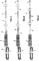
- the longitudinal, multi-stand rolling mill mainly includes (see figures 1.1, 1.2, 1.3 ) an inlet system 1 for pipe and mandrel bar, followed by a rolling mill 2, downstream of which is an outlet system 3 for pipe and mandrel bar, and finally an extracting rolling mill 4 placed at a distance from the rolling mill 2 larger than the maximum length possible for the pipe being processed and for mandrel bar.
- the distance between the axis of the last stand of the rolling mill 2 and the axis of the first stand of the extracting rolling mill 4 is the distance between rolling mill 2 and extracting rolling mill 4.
- the pipe when the pipe is released from the rolling mill 2, the pipe is not yet engaged with the extracting rolling mill 4, thus allowing the inlet speed of the pipe into the extracting rolling mill to be independent from the outlet speed from the rolling mill, and thus possibly ending processing the pipe in line.
- the mandrel bar is extracted at the outlet of the rolling mill 2 by means of the outlet system 3, laterally unloaded and then brought back to the inlet out of line, without interrupting the pipe processing.
- the processing cycle of the next pipe may begin by using another mandrel bar.
- the preceding mandrel bar is repositioned on the inlet system for successive processing, thus being exchanged with the previous one.
- the circulating mandrel bars are more than two as each mandrel bar between one rolling and the following requires to be cooled down and lubricated (these operations are known and are not the object of the present invention).
- Indicative sizes for the rolling mill object of the invention may be the following:
- FIG. 1.1 the three successive processing steps are indicated: a step with mandrel bar 5 on the inlet system 1 ( fig. 1.1 ); crossing step of the mandrel bar in the rolling mill 2 ( fig. 1.2 ); step with the mandrel baron the outlet system 3 ( fig. 1.3 ).
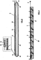
- the pipe is not indicated for simplicity, while the mandrel bar 5 is indicated (with greater detail in figure 2 ) comprising a processing head 10, followed by an extension 11, alternated by an intermediate compartment 12 having a smaller diameter, while a tang 13 is in the tail.
- the slot 12 is obtained in one piece from the extension 11 or, alternatively it could be obtained on an intermediate piece between the processing head 10 and the extension 11.
- the inlet system 1 is provided at the inlet of the rolling mill and comprises a mandrel bar restraining device which, in the suggested embodiment ( fig. 2 ), consists of a chain 15, with two star-pulleys 16, 17 at the two ends, and comprising at least two supporting pieces 18 (at an equal reciprocal distance on the chain) which are alternatively engaged (in two successive rolling operations) with the tang 13 of the spindle extension (box in fig. 2 ).
- the chain system is known per se, e.g. such as that existing in the rolling mills of semi-restrained type described above.
- Such an inlet system permits to automatically release the tang of the mandrel bar from the supporting piece in a fixed position, when the supporting piece itself winds on the star-pulley 17 arranged close to the inlet side of the rolling mill.
- the chain is motorized and its speed and position are controlled (the control is not shown for simplicity in the drawings). Once the tang 13 has been freed, the chain stops in such a position that the second supporting piece is in correspondence of the tang of the new mandrel bar which is loaded by means of an aerial manipulator of known type (not shown).
- the mandrel bar is preferably loaded at the inlet of the rolling mill already pre-inserted into the pipe to be rolled.
- the rollin mill 2 consists of a series of motorized rolling stands, alternated in groups by mandrel bar-holder stands.
- a descaling system outside the pipe may be provided upstream of the first stand.
- a last rounding stand may exist downstream.
- the morphology of the rolling mill is of known type; the number and type of stands is not a characterizing object of the invention.
- the outlet system 3 comprises ( fig. 3 ) a motorized roller path 20, which may be partially pulled down, comprising a series of rollers 21 to support the pipe and the mandrel bar.
- a movable catching device 6 and a fixed dampened stopping device 7 are provided and described below.
- Each roller of the motorized roller path which may come in contact with the catching device 6 is of the pulling down type by means of hydraulic systems or other systems all known per se. An example is described hereinafter.
- the section of rollers which may be pulled down starts from the outlet of the rolling mill 2 and may end at the stopping position of the catching device 6 against the fixed, dampened stopping device 7.
- the next section up to the extractor 4 may be fixed, e.g. in the case of a system with a single nominal size (calibre) at the outlet of the rolling mill.
- Guide tracks of the catching device 6 and fixed racks which engage the toothed wheels mounted to the catching device, are by the side of the roller path. An example is described hereinafter.
- the rolling mill according to the invention is a rolling mill of restrained type, in which the pipe rolling occurs at a calculated, set speed of the mandrel bar, in which when the tail of the pipe is released from the last stand of the rolling mill 2, the pipe is not yet engaged with the extracting rolling mill 4, as the first stand of the extractor is at a distance from the last stand of the rolling mill 2 larger than the maximum length of the producible pipe.
- this condition permits to render the inlet speed of the extractor independent from the outlet speed of the rolling mill.
- the catching device 6, in a stationary position just downstream of the rolling mill 2, is accelerated and brought into synchrony with the speed of the spindle.
- the position of the mandrel bar is known, as the restraining device placed on the inlet side of the rolling mill 2 is still engaged with the tang 13 at the tail end of the extension.
- the catching device 6 is engaged with the intermediate compartment 12 arranged on the extension lose to the connection point between the extension and the working part of the mandrel bar.
- the catching device 6 continues its stroke while withdrawing the extension from the rolling mill 2 and bringing the mandrel bar (working part and extension) to a fixed unloading position between the rolling mill and the extractor (the total length of the mandrel bar is less than the distance between the rolling mill 2 and the extractor 4).
- the fixed, dampened stopping device absorbs the kinetic energy of the catching device and of the mandrel bar connected thereto, and exerts the reaction required to balance the pull exerted by the extractor.
- the catching device 6 substantially stops in a fixed position as it progressively impacts with the dampened stopping device 7.
- the latter may essentially consists of, for example, two hydraulic cylinders suitably arranged on the two sides of the guide tracks of the catching device. These cylinders are characterized by a hydraulic braking system (not indicated).
- the heads of the two pistons of the hydraulic cylinders are engaged with the structural part 43 of the catching device, adjacent to the position of the mandrel bar, at an equal height, thus avoiding the occurrence of overturning actions on the cart of the catching device.
- a rapid transversal unloading device laterally unloads the mandrel bar, before the successive pipe arrives.
- the catching device 6 substantially is a cart 40 which moves on wheels, on the rail 44 the tracks of which are placed at the two sides of the roller path.
- Six support wheels 41 and four counter wheels 42 serving an overturning preventing function are present in the embodiment.
- the tracks on the unloading side of the spindle are interrupted in sections 46 to permit a series of rotating arms 45 (technically known) to pass, thus permitting the transversal evacuation of the mandrel bar.
- the cart 40 is motorized by means of two motors 48 connected to two pinions arranged at a vertical axis by means of reducers 49.
- Each pinion is engaged with two toothed wheels 51, the longitudinal pitch of which is always larger than the compartment on the spindle unloading side which interrupts the fixed counter-rack 52.
- the rack 53 on the opposite side is continuous.
- the solution described permits an automatic mechanical phasing system of the two toothed wheels which are engaged with the discontinuous rack, thus permitting to automatically find the phase of the teeth again, when the toothed wheel is rolled on the rack downstream of an interruption 46.
- a hooking device is mounted on the catching device which, in the example shown, is made in the form of an overturnable hinged guillotine group 55, between a lowered resting position and a working position, in which the guillotine 56 is engaged with the slot 12 arranged in the spindle extension.
- the guillotine group 55 is controlled by linkages 57 by means of a reducer and an electric motor.
- the solution described has the advantage that, once the guillotine 56 has been brought to the working position, it rests at the two sides of the structure of the cart 40 thus avoiding to overload the linkages 57 during the step of extracting the pipe from the mandrel bar.
- the embodiment includes using a rotating arm system 45, for the transversal evacuation of the mandrel bar, known per se in the art.
- the rotating arm system 45 is developed on the unloading side of the mandrel bar over the competent section of the length of the mandrel bar, at the stopping and evacuation position of the spindle itself.
- the system substantially provides for the arm 45 rotating about a pivot 50, so as to always keep the plate 47 which supports the spindle 5 with the same inclination.
- the arm lifts the mandrel bar from the bottom, starting from the lowered position underneath, lifts it and transports it transversally out of the roller path, while stopping in the lateral position, from where the mandrel bar is then taken by a system (not shown in the drawings and not described in detail as known per se), and then brought towards the inlet system 1.
- the rotating arm completes its rotation and is brought back to the waiting position under the roller path and out of interference with the catching device 6, which may reversely transit to position itself at the starting point again for the next rolling cycle.
- FIG. 4.1 An example of motorized roller 21 of the roller path is shown in figures 4.1 and 4.3 .
- the roller 21 may take the lowered position 21.1 or the raised position 21.2, being controlled by a pulling down system 62 with linkages 65 by means of the actuator 67, which rotate the arm 60 of the roller. Instead, a motor 64 with associated chains 66 and 63 controls the rotation of the roller.
- the cycle time of the system permits the production of 3-4 pieces per minute.
- An advantage of the invention is that as the speeds of the rolling mill and of the extractor are free, the extractor may also serve the function of calibrator (or possibly of stretch reducing mill) by directly finishing the pipes in line without intermediate fossil heating.
- a possible induction furnace may be inserted in this case between the unloading position of the mandrel bar and the extracting rolling mill.
- the rolling mill according to the invention includes a rounding stand downstream of the true rolling stands. Such a stand permits to withdraw the pipe from the spindle without difficulty, even if pipe and mandrel bar were in contact for some seconds without relative speed; the contact time is greater in the case of short (normally thick) pipes.
- the temperature of the pipe along its axis is much more uniform than that obtained by the floating mandrel bar and/or semi-restrained spindle processes, as in the latter the mandrel bar is partially inserted into the pipe; therefore, the head of the pipe is much hotter than the tail, also because of the increased pipe-mandrel bar contact time due to the out-of-line withdrawal typically actuated with a chain and guillotine device.
Landscapes
- Engineering & Computer Science (AREA)
- Mechanical Engineering (AREA)
- Metal Rolling (AREA)
- Control Of Metal Rolling (AREA)
- Lining Or Joining Of Plastics Or The Like (AREA)
- Laminated Bodies (AREA)
Claims (7)
- Verfahren zum Walzen von Hohlkörpern in einem mehrgerüstigen Längs-Walzwerk des kontinuierlichen gebremsten Typs, wobei das Walzwerk umfasst: ein Haupt-Walzwerk (2) und ein Abzieh-Walzwerk (4) in Reihe mit dem und nachgelagert dem Haupt-Walzwerk, wobei das Haupt-Walzwerk und das Abzieh-Walzwerk befähigt sind, den Hohlkörper in Kooperation mit wenigstens einer Dorn-Stange (5) zu verarbeiten, wobei das Verfahren gekennzeichnet ist durch die folgenden Schritte:- Positionieren des Abzieh-Walzwerks in einer Entfernung von dem Haupt-Walzwerk, die größer ist als die maximale Länge des Hohlkörpers und der Dorn-Stange;- Abziehen der Dorn-Stange am Auslass des Haupt-Walzwerks in dem Zwischenraum zwischen dem Haupt-Walzwerk und dem Abzieh-Walzwerk und deren seitliches Entladen.
- Walzverfahren nach Anspruch 1, weiter umfassend die Schritte:- nach dem seitlichen Entladen Rückführen der Dorn-Stange (5) zum Einlass des Haupt-Walzwerks (2) außerhalb der Reihe;- Beginnen des Verarbeitens eines nachfolgenden Hohlkörpers unter Verwendung einer anderen Dorn-Stange während des Schritts des Rückführens der Dorn-Stange (5) zum Einlass.
- Walzverfahren nach Anspruch 1, worin der Schritt des Abziehens der Dorn-Stange am Auslass des Haupt-Walzwerks und des seitlichen Entladens umfasst:- Greifen der Dorn-Stange durch Synchronisieren der Geschwindigkeit des Hohlkörpers und der Dorn-Stange am Auslass des Haupt-Walzwerks mit der Geschwindigkeit am Einlass des Abzieh-Walzwerks;- Verlangsamen der Dorn-Stange, bis sie anhält, so dass sie von dem Hohlkörper losgelöst wird, der - sobald er aus dem Haupt-Walzwerk austritt - in das Abzieh-Walzwerk eintritt;- Entladen der Dorn-Stange in Querrichtung im Hinblick auf die Ruhe-Position.
- Mehrgerüstiges Längs-Walzwerk für Hohlkörper für die Realisierung des Verfahrens nach irgendeinem der vorangehenden Ansprüche, umfassend- ein Haupt-Walzwerk (2) und ein Abzieh-Walzwerk (4) in Reihe mit dem und nachgelagert dem Haupt-Walzwerk, wobei das Haupt-Walzwerk und das Abzieh-Walzwerk befähigt sind, den Hohlkörper in Kooperation mit wenigstens einer Dorn-Stange (5) zu verarbeiten, wobei das Abzieh-Walzwerk in einer Entfernung von dem Haupt-Walzwerk platziert ist, die größer ist als die maximale Länge des Hohlkörpers und der Dorn-Stange;- Mittel zum Abziehen der Dorn-Stange am Auslass des Haupt-Walzwerks in dem Zwischenraum zwischen dem Haupt-Walzwerk und dem Abzieh-Walzwerk und zu deren seitlichem Entladen; wobei- die Mittel zum Abziehen der Dorn-Stange am Auslass des Haupt-Walzwerks und zu deren seitlichem Entladen umfassen:- Mittel zum Greifen der Dorn-Stange durch Synchronisieren der Geschwindigkeit des Hohlkörpers und der Dorn-Stange am Auslass des Haupt-Walzwerks mit der Geschwindigkeit am Einlass des Abzieh-Walzwerks;- Mittel zum Verlangsamen der Dorn-Stange, bis sie anhält, so dass sie von dem Hohlkörper losgelöst wird, der - sobald er aus dem Haupt-Walzwerk austritt - in das Abzieh-Walzwerk eintritt;- Mittel zum Entladen der Dorn-Stange in Querrichtung im Hinblick auf die Ruhe-Position; und- wobei bereitgestellt wird ein motorisierter Walzen-Weg (20), der partiell heruntergezogen werden kann, in dem Zwischenraum zwischen dem Haupt-Walzwerk und dem Abzieh-Walzwerk zum Tragen des Rohrs und der Dorn-Stange.
- Längs-Walzwerk nach Anspruch 4, worin die Mittel zum Greifen der Dorn-Stange eine Greif-Vorrichtung (6), die einen motorisierten Wagen (40) umfasst, der sich parallel zu dem motorisierten Walzen-Weg (20) bewegt, und eine kippbare Einhak-Vorrichtung (55) umfassen, um die Dorn-Stange auf ihrem Weg zu greifen und sie freizugeben, wenn sie anhält.
- Längs-Walzwerk nach Anspruch 5, worin die Mittel zum Verlangsamen der Dorn-Stange, bis sie anhält, eine gedämpfte Anhalte-Vorrichtung (7) zum schrittweisen Stoppen der Fortbewegung der Greif-Vorrichtung (6) umfassen.
- Längs-Walzwerk nach Anspruch 6, worin die Mittel zum Entladen der Dorn-stange in Querrichtung zu der Ruheposition ein Dreh-Arm-System (45) umfassen, um die Dorn-Stange in ihre Ruheposition anzuheben, wenn die kippbare Einhak-Vorrichtung (55) die Dorn-Stange freigibt, und um sie in eine Quer-Außenposition zu bringen.
Applications Claiming Priority (2)
| Application Number | Priority Date | Filing Date | Title |
|---|---|---|---|
| ITMI2009A001143A IT1395593B1 (it) | 2009-06-29 | 2009-06-29 | Procedimento di laminazione e relativo laminatoio longitudinale multi gabbia di tipo trattenuto e continuo per corpi cavi |
| PCT/EP2010/059182 WO2011000819A2 (en) | 2009-06-29 | 2010-06-29 | Rolling process and relating longitudinal, multi-stand rolling mill of continuous, restrained type for hollow bodies |
Publications (4)
| Publication Number | Publication Date |
|---|---|
| EP2448686A2 EP2448686A2 (de) | 2012-05-09 |
| EP2448686B1 EP2448686B1 (de) | 2014-04-16 |
| EP2448686B2 true EP2448686B2 (de) | 2018-03-28 |
| EP2448686B9 EP2448686B9 (de) | 2018-09-19 |
Family
ID=42111907
Family Applications (1)
| Application Number | Title | Priority Date | Filing Date |
|---|---|---|---|
| EP10748066.7A Active EP2448686B9 (de) | 2009-06-29 | 2010-06-29 | Walzverfahren und zugehöriges mehrgerüstiges kontinuierliches gebremstes längswalzwerk für hohlkörper |
Country Status (7)
| Country | Link |
|---|---|
| US (1) | US8429945B2 (de) |
| EP (1) | EP2448686B9 (de) |
| CN (1) | CN102802828B (de) |
| BR (1) | BRPI1015357B1 (de) |
| IT (1) | IT1395593B1 (de) |
| RU (1) | RU2500491C2 (de) |
| WO (1) | WO2011000819A2 (de) |
Families Citing this family (4)
| Publication number | Priority date | Publication date | Assignee | Title |
|---|---|---|---|---|
| ITMI20110372A1 (it) * | 2011-03-10 | 2012-09-11 | Danieli Off Mecc | Processo di laminazione per tubi in laminatoio continuo multigabbia |
| ITMI20110573A1 (it) | 2011-04-07 | 2012-10-08 | Danieli Off Mecc | Dispositivo di convogliamento di mandrino per impianto di laminazione di tubi |
| IT201700023064A1 (it) * | 2017-03-01 | 2018-09-01 | Danieli Off Mecc | Laminatoio per la laminazione di elementi astiformi cavi o comunque concavi |
| CN116833237B (zh) * | 2023-09-01 | 2023-10-31 | 太原科技大学 | 一种难变形薄壁金属管坯的三辊旋轧生产线 |
Citations (2)
| Publication number | Priority date | Publication date | Assignee | Title |
|---|---|---|---|---|
| DE2716917A1 (de) † | 1976-07-30 | 1978-02-02 | Aetna Standard Eng Co | Verfahren und vorrichtung zum durchfuehren von stopfenwalzvorgaengen |
| EP2318159B1 (de) † | 2008-08-25 | 2013-09-18 | SMS Meer GmbH | Verfahren zur herstellung eines nahtlosen stahlrohres und walzwerk zur durchführung des verfahrens |
Family Cites Families (7)
| Publication number | Priority date | Publication date | Assignee | Title |
|---|---|---|---|---|
| DE2811801A1 (de) * | 1978-03-15 | 1979-09-20 | Mannesmann Ag | Verfahren und anlage zum warmwalzen nahtloser rohre |
| SU776695A1 (ru) * | 1978-08-21 | 1980-11-07 | Уральский научно-исследовательский институт трубной промышленности | Способ извлечени длинной оправки из трубы |
| DE3333390A1 (de) * | 1983-09-13 | 1985-03-21 | Mannesmann AG, 4000 Düsseldorf | Vorrichtung zum zu- und abfuehren der dornstangen an schraeg- und laengswalzwerken |
| EP1463591B1 (de) * | 2002-01-09 | 2005-06-01 | SMS Meer GmbH | Verfahren und walzanlage zum herstellen von draht, stäben oder nahtlosen rohren |
| DE10261632B4 (de) * | 2002-01-09 | 2004-09-09 | Sms Meer Gmbh | Verfahren und Walzanlage zum Herstellen von Draht, Stäben oder nahtlosen Rohren |
| WO2006090718A1 (ja) * | 2005-02-22 | 2006-08-31 | Sumitomo Metal Industries, Ltd. | 継目無管の製造方法及び清掃設備 |
| DE102005044777A1 (de) * | 2005-09-20 | 2007-03-29 | Sms Meer Gmbh | Verfahren und Walzwerk zur Herstellung eines nahtlosen Rohres |
-
2009
- 2009-06-29 IT ITMI2009A001143A patent/IT1395593B1/it active
-
2010
- 2010-06-29 RU RU2012102982/02A patent/RU2500491C2/ru active
- 2010-06-29 CN CN201080027741.9A patent/CN102802828B/zh active Active
- 2010-06-29 WO PCT/EP2010/059182 patent/WO2011000819A2/en not_active Ceased
- 2010-06-29 BR BRPI1015357A patent/BRPI1015357B1/pt not_active IP Right Cessation
- 2010-06-29 EP EP10748066.7A patent/EP2448686B9/de active Active
- 2010-06-29 US US13/379,625 patent/US8429945B2/en active Active
Patent Citations (2)
| Publication number | Priority date | Publication date | Assignee | Title |
|---|---|---|---|---|
| DE2716917A1 (de) † | 1976-07-30 | 1978-02-02 | Aetna Standard Eng Co | Verfahren und vorrichtung zum durchfuehren von stopfenwalzvorgaengen |
| EP2318159B1 (de) † | 2008-08-25 | 2013-09-18 | SMS Meer GmbH | Verfahren zur herstellung eines nahtlosen stahlrohres und walzwerk zur durchführung des verfahrens |
Also Published As
| Publication number | Publication date |
|---|---|
| IT1395593B1 (it) | 2012-10-16 |
| BRPI1015357A2 (pt) | 2016-10-25 |
| CN102802828A (zh) | 2012-11-28 |
| EP2448686B1 (de) | 2014-04-16 |
| EP2448686A2 (de) | 2012-05-09 |
| CN102802828B (zh) | 2015-07-29 |
| US8429945B2 (en) | 2013-04-30 |
| RU2500491C2 (ru) | 2013-12-10 |
| WO2011000819A3 (en) | 2011-03-24 |
| RU2012102982A (ru) | 2013-08-10 |
| WO2011000819A2 (en) | 2011-01-06 |
| ITMI20091143A1 (it) | 2010-12-30 |
| EP2448686B9 (de) | 2018-09-19 |
| BRPI1015357B1 (pt) | 2020-04-07 |
| US20120103049A1 (en) | 2012-05-03 |
Similar Documents
| Publication | Publication Date | Title |
|---|---|---|
| EP2519366B1 (de) | Wickel- / abwickelvorrichtung und verfahren in einer metalwalzstrasse | |
| EP2694227B1 (de) | Dornfördervorrichtung für ein rohrwalzwerk | |
| EP2448686B2 (de) | Walzverfahren und zugehöriges mehrgerüstiges kontinuierliches gebremstes längswalzwerk für hohlkörper | |
| CN108746219B (zh) | 不同材质热轧扁钢共线生产的步进冷床设备及生产方法 | |
| CN104781020B (zh) | 皮尔格式轧机机列 | |
| US9283599B2 (en) | Process for rolling tubes in a continuous multi-stand rolling mill | |
| US8046901B2 (en) | Compact plant for continuous production of bars and/or profiles | |
| CA1198917A (en) | Billet centering and control guide for the entry guide of a press-piercing mill | |
| CN114192578B (zh) | 带钢轧制效能高效释放工艺及设备 | |
| KR20180117669A (ko) | 단순 롤 스탠드 구조에서 인라인 롤 교체 | |
| CN105188974A (zh) | 用于无缝管的集成横轧机 |
Legal Events
| Date | Code | Title | Description |
|---|---|---|---|
| PUAI | Public reference made under article 153(3) epc to a published international application that has entered the european phase |
Free format text: ORIGINAL CODE: 0009012 |
|
| 17P | Request for examination filed |
Effective date: 20120126 |
|
| AK | Designated contracting states |
Kind code of ref document: A2 Designated state(s): AL AT BE BG CH CY CZ DE DK EE ES FI FR GB GR HR HU IE IS IT LI LT LU LV MC MK MT NL NO PL PT RO SE SI SK SM TR |
|
| DAX | Request for extension of the european patent (deleted) | ||
| GRAP | Despatch of communication of intention to grant a patent |
Free format text: ORIGINAL CODE: EPIDOSNIGR1 |
|
| INTG | Intention to grant announced |
Effective date: 20131107 |
|
| GRAS | Grant fee paid |
Free format text: ORIGINAL CODE: EPIDOSNIGR3 |
|
| GRAA | (expected) grant |
Free format text: ORIGINAL CODE: 0009210 |
|
| AK | Designated contracting states |
Kind code of ref document: B1 Designated state(s): AL AT BE BG CH CY CZ DE DK EE ES FI FR GB GR HR HU IE IS IT LI LT LU LV MC MK MT NL NO PL PT RO SE SI SK SM TR |
|
| REG | Reference to a national code |
Ref country code: GB Ref legal event code: FG4D |
|
| REG | Reference to a national code |
Ref country code: CH Ref legal event code: EP |
|
| REG | Reference to a national code |
Ref country code: AT Ref legal event code: REF Ref document number: 662185 Country of ref document: AT Kind code of ref document: T Effective date: 20140515 |
|
| REG | Reference to a national code |
Ref country code: IE Ref legal event code: FG4D |
|
| REG | Reference to a national code |
Ref country code: DE Ref legal event code: R096 Ref document number: 602010015199 Country of ref document: DE Effective date: 20140528 |
|
| REG | Reference to a national code |
Ref country code: NL Ref legal event code: VDEP Effective date: 20140416 |
|
| REG | Reference to a national code |
Ref country code: LT Ref legal event code: MG4D |
|
| PG25 | Lapsed in a contracting state [announced via postgrant information from national office to epo] |
Ref country code: BG Free format text: LAPSE BECAUSE OF FAILURE TO SUBMIT A TRANSLATION OF THE DESCRIPTION OR TO PAY THE FEE WITHIN THE PRESCRIBED TIME-LIMIT Effective date: 20140716 Ref country code: FI Free format text: LAPSE BECAUSE OF FAILURE TO SUBMIT A TRANSLATION OF THE DESCRIPTION OR TO PAY THE FEE WITHIN THE PRESCRIBED TIME-LIMIT Effective date: 20140416 Ref country code: LT Free format text: LAPSE BECAUSE OF FAILURE TO SUBMIT A TRANSLATION OF THE DESCRIPTION OR TO PAY THE FEE WITHIN THE PRESCRIBED TIME-LIMIT Effective date: 20140416 Ref country code: IS Free format text: LAPSE BECAUSE OF FAILURE TO SUBMIT A TRANSLATION OF THE DESCRIPTION OR TO PAY THE FEE WITHIN THE PRESCRIBED TIME-LIMIT Effective date: 20140816 Ref country code: CY Free format text: LAPSE BECAUSE OF FAILURE TO SUBMIT A TRANSLATION OF THE DESCRIPTION OR TO PAY THE FEE WITHIN THE PRESCRIBED TIME-LIMIT Effective date: 20140416 Ref country code: NL Free format text: LAPSE BECAUSE OF FAILURE TO SUBMIT A TRANSLATION OF THE DESCRIPTION OR TO PAY THE FEE WITHIN THE PRESCRIBED TIME-LIMIT Effective date: 20140416 Ref country code: NO Free format text: LAPSE BECAUSE OF FAILURE TO SUBMIT A TRANSLATION OF THE DESCRIPTION OR TO PAY THE FEE WITHIN THE PRESCRIBED TIME-LIMIT Effective date: 20140716 |
|
| PG25 | Lapsed in a contracting state [announced via postgrant information from national office to epo] |
Ref country code: ES Free format text: LAPSE BECAUSE OF FAILURE TO SUBMIT A TRANSLATION OF THE DESCRIPTION OR TO PAY THE FEE WITHIN THE PRESCRIBED TIME-LIMIT Effective date: 20140416 Ref country code: SE Free format text: LAPSE BECAUSE OF FAILURE TO SUBMIT A TRANSLATION OF THE DESCRIPTION OR TO PAY THE FEE WITHIN THE PRESCRIBED TIME-LIMIT Effective date: 20140416 Ref country code: HR Free format text: LAPSE BECAUSE OF FAILURE TO SUBMIT A TRANSLATION OF THE DESCRIPTION OR TO PAY THE FEE WITHIN THE PRESCRIBED TIME-LIMIT Effective date: 20140416 Ref country code: LV Free format text: LAPSE BECAUSE OF FAILURE TO SUBMIT A TRANSLATION OF THE DESCRIPTION OR TO PAY THE FEE WITHIN THE PRESCRIBED TIME-LIMIT Effective date: 20140416 Ref country code: PL Free format text: LAPSE BECAUSE OF FAILURE TO SUBMIT A TRANSLATION OF THE DESCRIPTION OR TO PAY THE FEE WITHIN THE PRESCRIBED TIME-LIMIT Effective date: 20140416 |
|
| PG25 | Lapsed in a contracting state [announced via postgrant information from national office to epo] |
Ref country code: PT Free format text: LAPSE BECAUSE OF FAILURE TO SUBMIT A TRANSLATION OF THE DESCRIPTION OR TO PAY THE FEE WITHIN THE PRESCRIBED TIME-LIMIT Effective date: 20140818 |
|
| REG | Reference to a national code |
Ref country code: DE Ref legal event code: R026 Ref document number: 602010015199 Country of ref document: DE |
|
| PLBI | Opposition filed |
Free format text: ORIGINAL CODE: 0009260 |
|
| PG25 | Lapsed in a contracting state [announced via postgrant information from national office to epo] |
Ref country code: EE Free format text: LAPSE BECAUSE OF FAILURE TO SUBMIT A TRANSLATION OF THE DESCRIPTION OR TO PAY THE FEE WITHIN THE PRESCRIBED TIME-LIMIT Effective date: 20140416 Ref country code: BE Free format text: LAPSE BECAUSE OF FAILURE TO SUBMIT A TRANSLATION OF THE DESCRIPTION OR TO PAY THE FEE WITHIN THE PRESCRIBED TIME-LIMIT Effective date: 20140416 Ref country code: DK Free format text: LAPSE BECAUSE OF FAILURE TO SUBMIT A TRANSLATION OF THE DESCRIPTION OR TO PAY THE FEE WITHIN THE PRESCRIBED TIME-LIMIT Effective date: 20140416 Ref country code: RO Free format text: LAPSE BECAUSE OF FAILURE TO SUBMIT A TRANSLATION OF THE DESCRIPTION OR TO PAY THE FEE WITHIN THE PRESCRIBED TIME-LIMIT Effective date: 20140416 Ref country code: LU Free format text: LAPSE BECAUSE OF FAILURE TO SUBMIT A TRANSLATION OF THE DESCRIPTION OR TO PAY THE FEE WITHIN THE PRESCRIBED TIME-LIMIT Effective date: 20140629 Ref country code: SK Free format text: LAPSE BECAUSE OF FAILURE TO SUBMIT A TRANSLATION OF THE DESCRIPTION OR TO PAY THE FEE WITHIN THE PRESCRIBED TIME-LIMIT Effective date: 20140416 Ref country code: CZ Free format text: LAPSE BECAUSE OF FAILURE TO SUBMIT A TRANSLATION OF THE DESCRIPTION OR TO PAY THE FEE WITHIN THE PRESCRIBED TIME-LIMIT Effective date: 20140416 Ref country code: MC Free format text: LAPSE BECAUSE OF FAILURE TO SUBMIT A TRANSLATION OF THE DESCRIPTION OR TO PAY THE FEE WITHIN THE PRESCRIBED TIME-LIMIT Effective date: 20140416 |
|
| REG | Reference to a national code |
Ref country code: CH Ref legal event code: PL |
|
| PLAX | Notice of opposition and request to file observation + time limit sent |
Free format text: ORIGINAL CODE: EPIDOSNOBS2 |
|
| 26 | Opposition filed |
Opponent name: SMS MEER GMBH Effective date: 20150116 |
|
| GBPC | Gb: european patent ceased through non-payment of renewal fee |
Effective date: 20140716 |
|
| REG | Reference to a national code |
Ref country code: IE Ref legal event code: MM4A |
|
| REG | Reference to a national code |
Ref country code: DE Ref legal event code: R026 Ref document number: 602010015199 Country of ref document: DE Effective date: 20150116 |
|
| PG25 | Lapsed in a contracting state [announced via postgrant information from national office to epo] |
Ref country code: LI Free format text: LAPSE BECAUSE OF NON-PAYMENT OF DUE FEES Effective date: 20140630 Ref country code: IE Free format text: LAPSE BECAUSE OF NON-PAYMENT OF DUE FEES Effective date: 20140629 Ref country code: CH Free format text: LAPSE BECAUSE OF NON-PAYMENT OF DUE FEES Effective date: 20140630 |
|
| PG25 | Lapsed in a contracting state [announced via postgrant information from national office to epo] |
Ref country code: GB Free format text: LAPSE BECAUSE OF NON-PAYMENT OF DUE FEES Effective date: 20140716 |
|
| PLAF | Information modified related to communication of a notice of opposition and request to file observations + time limit |
Free format text: ORIGINAL CODE: EPIDOSCOBS2 |
|
| PG25 | Lapsed in a contracting state [announced via postgrant information from national office to epo] |
Ref country code: SI Free format text: LAPSE BECAUSE OF FAILURE TO SUBMIT A TRANSLATION OF THE DESCRIPTION OR TO PAY THE FEE WITHIN THE PRESCRIBED TIME-LIMIT Effective date: 20140416 |
|
| PLBB | Reply of patent proprietor to notice(s) of opposition received |
Free format text: ORIGINAL CODE: EPIDOSNOBS3 |
|
| PG25 | Lapsed in a contracting state [announced via postgrant information from national office to epo] |
Ref country code: MT Free format text: LAPSE BECAUSE OF FAILURE TO SUBMIT A TRANSLATION OF THE DESCRIPTION OR TO PAY THE FEE WITHIN THE PRESCRIBED TIME-LIMIT Effective date: 20140416 |
|
| PG25 | Lapsed in a contracting state [announced via postgrant information from national office to epo] |
Ref country code: SM Free format text: LAPSE BECAUSE OF FAILURE TO SUBMIT A TRANSLATION OF THE DESCRIPTION OR TO PAY THE FEE WITHIN THE PRESCRIBED TIME-LIMIT Effective date: 20140416 |
|
| REG | Reference to a national code |
Ref country code: FR Ref legal event code: PLFP Year of fee payment: 7 |
|
| PG25 | Lapsed in a contracting state [announced via postgrant information from national office to epo] |
Ref country code: GR Free format text: LAPSE BECAUSE OF FAILURE TO SUBMIT A TRANSLATION OF THE DESCRIPTION OR TO PAY THE FEE WITHIN THE PRESCRIBED TIME-LIMIT Effective date: 20140416 |
|
| PG25 | Lapsed in a contracting state [announced via postgrant information from national office to epo] |
Ref country code: HU Free format text: LAPSE BECAUSE OF FAILURE TO SUBMIT A TRANSLATION OF THE DESCRIPTION OR TO PAY THE FEE WITHIN THE PRESCRIBED TIME-LIMIT; INVALID AB INITIO Effective date: 20100629 Ref country code: TR Free format text: LAPSE BECAUSE OF FAILURE TO SUBMIT A TRANSLATION OF THE DESCRIPTION OR TO PAY THE FEE WITHIN THE PRESCRIBED TIME-LIMIT Effective date: 20140416 |
|
| PLAB | Opposition data, opponent's data or that of the opponent's representative modified |
Free format text: ORIGINAL CODE: 0009299OPPO |
|
| R26 | Opposition filed (corrected) |
Opponent name: SMS GROUP GMBH Effective date: 20150116 |
|
| REG | Reference to a national code |
Ref country code: FR Ref legal event code: PLFP Year of fee payment: 8 |
|
| APAH | Appeal reference modified |
Free format text: ORIGINAL CODE: EPIDOSCREFNO |
|
| APBM | Appeal reference recorded |
Free format text: ORIGINAL CODE: EPIDOSNREFNO |
|
| APBP | Date of receipt of notice of appeal recorded |
Free format text: ORIGINAL CODE: EPIDOSNNOA2O |
|
| APBU | Appeal procedure closed |
Free format text: ORIGINAL CODE: EPIDOSNNOA9O |
|
| RIN2 | Information on inventor provided after grant (corrected) |
Inventor name: CERNUSCHI, ETTORE Inventor name: LATTANZI, MAURO |
|
| PUAH | Patent maintained in amended form |
Free format text: ORIGINAL CODE: 0009272 |
|
| STAA | Information on the status of an ep patent application or granted ep patent |
Free format text: STATUS: PATENT MAINTAINED AS AMENDED |
|
| 27A | Patent maintained in amended form |
Effective date: 20180328 |
|
| AK | Designated contracting states |
Kind code of ref document: B2 Designated state(s): AL AT BE BG CH CY CZ DE DK EE ES FI FR GB GR HR HU IE IS IT LI LT LU LV MC MK MT NL NO PL PT RO SE SI SK SM TR |
|
| REG | Reference to a national code |
Ref country code: DE Ref legal event code: R102 Ref document number: 602010015199 Country of ref document: DE |
|
| REG | Reference to a national code |
Ref country code: FR Ref legal event code: PLFP Year of fee payment: 9 |
|
| PG25 | Lapsed in a contracting state [announced via postgrant information from national office to epo] |
Ref country code: MK Free format text: LAPSE BECAUSE OF FAILURE TO SUBMIT A TRANSLATION OF THE DESCRIPTION OR TO PAY THE FEE WITHIN THE PRESCRIBED TIME-LIMIT Effective date: 20140416 |
|
| REG | Reference to a national code |
Ref country code: AT Ref legal event code: MK05 Ref document number: 662185 Country of ref document: AT Kind code of ref document: T Effective date: 20180328 |
|
| PGFP | Annual fee paid to national office [announced via postgrant information from national office to epo] |
Ref country code: BG Payment date: 20181228 Year of fee payment: 10 |
|
| PG25 | Lapsed in a contracting state [announced via postgrant information from national office to epo] |
Ref country code: AL Free format text: LAPSE BECAUSE OF FAILURE TO SUBMIT A TRANSLATION OF THE DESCRIPTION OR TO PAY THE FEE WITHIN THE PRESCRIBED TIME-LIMIT Effective date: 20140416 |
|
| PG25 | Lapsed in a contracting state [announced via postgrant information from national office to epo] |
Ref country code: AT Free format text: LAPSE BECAUSE OF FAILURE TO SUBMIT A TRANSLATION OF THE DESCRIPTION OR TO PAY THE FEE WITHIN THE PRESCRIBED TIME-LIMIT Effective date: 20180328 |
|
| PGFP | Annual fee paid to national office [announced via postgrant information from national office to epo] |
Ref country code: FR Payment date: 20200520 Year of fee payment: 11 |
|
| PG25 | Lapsed in a contracting state [announced via postgrant information from national office to epo] |
Ref country code: FR Free format text: LAPSE BECAUSE OF NON-PAYMENT OF DUE FEES Effective date: 20210630 |
|
| PGFP | Annual fee paid to national office [announced via postgrant information from national office to epo] |
Ref country code: DE Payment date: 20250627 Year of fee payment: 16 |
|
| PGFP | Annual fee paid to national office [announced via postgrant information from national office to epo] |
Ref country code: IT Payment date: 20250619 Year of fee payment: 16 |