EP2447600A2 - Unité d'éclairage - Google Patents
Unité d'éclairage Download PDFInfo
- Publication number
- EP2447600A2 EP2447600A2 EP11008605A EP11008605A EP2447600A2 EP 2447600 A2 EP2447600 A2 EP 2447600A2 EP 11008605 A EP11008605 A EP 11008605A EP 11008605 A EP11008605 A EP 11008605A EP 2447600 A2 EP2447600 A2 EP 2447600A2
- Authority
- EP
- European Patent Office
- Prior art keywords
- light
- fluorescent
- fluorescent member
- lighting unit
- type lens
- Prior art date
- Legal status (The legal status is an assumption and is not a legal conclusion. Google has not performed a legal analysis and makes no representation as to the accuracy of the status listed.)
- Granted
Links
- 238000009826 distribution Methods 0.000 claims abstract description 85
- 230000003287 optical effect Effects 0.000 claims abstract description 22
- 239000000463 material Substances 0.000 claims description 36
- 239000004065 semiconductor Substances 0.000 claims description 14
- 238000009792 diffusion process Methods 0.000 claims description 12
- 230000005284 excitation Effects 0.000 description 16
- 230000002093 peripheral effect Effects 0.000 description 5
- VTYYLEPIZMXCLO-UHFFFAOYSA-L Calcium carbonate Chemical compound [Ca+2].[O-]C([O-])=O VTYYLEPIZMXCLO-UHFFFAOYSA-L 0.000 description 4
- JNDMLEXHDPKVFC-UHFFFAOYSA-N aluminum;oxygen(2-);yttrium(3+) Chemical compound [O-2].[O-2].[O-2].[Al+3].[Y+3] JNDMLEXHDPKVFC-UHFFFAOYSA-N 0.000 description 4
- 238000010586 diagram Methods 0.000 description 4
- 229910019901 yttrium aluminum garnet Inorganic materials 0.000 description 4
- 230000004907 flux Effects 0.000 description 3
- 238000005245 sintering Methods 0.000 description 3
- GWEVSGVZZGPLCZ-UHFFFAOYSA-N Titan oxide Chemical compound O=[Ti]=O GWEVSGVZZGPLCZ-UHFFFAOYSA-N 0.000 description 2
- 239000000654 additive Substances 0.000 description 2
- 230000000996 additive effect Effects 0.000 description 2
- PNEYBMLMFCGWSK-UHFFFAOYSA-N aluminium oxide Inorganic materials [O-2].[O-2].[O-2].[Al+3].[Al+3] PNEYBMLMFCGWSK-UHFFFAOYSA-N 0.000 description 2
- 239000011230 binding agent Substances 0.000 description 2
- 229910000019 calcium carbonate Inorganic materials 0.000 description 2
- 230000000694 effects Effects 0.000 description 2
- 230000017525 heat dissipation Effects 0.000 description 2
- 229910052761 rare earth metal Inorganic materials 0.000 description 2
- 150000002910 rare earth metals Chemical class 0.000 description 2
- 239000011347 resin Substances 0.000 description 2
- 229920005989 resin Polymers 0.000 description 2
- 238000007493 shaping process Methods 0.000 description 2
- OGIDPMRJRNCKJF-UHFFFAOYSA-N titanium oxide Inorganic materials [Ti]=O OGIDPMRJRNCKJF-UHFFFAOYSA-N 0.000 description 2
- RYGMFSIKBFXOCR-UHFFFAOYSA-N Copper Chemical compound [Cu] RYGMFSIKBFXOCR-UHFFFAOYSA-N 0.000 description 1
- 239000000853 adhesive Substances 0.000 description 1
- 230000001070 adhesive effect Effects 0.000 description 1
- 229910052782 aluminium Inorganic materials 0.000 description 1
- XAGFODPZIPBFFR-UHFFFAOYSA-N aluminium Chemical compound [Al] XAGFODPZIPBFFR-UHFFFAOYSA-N 0.000 description 1
- 230000033228 biological regulation Effects 0.000 description 1
- 230000001427 coherent effect Effects 0.000 description 1
- 229910052802 copper Inorganic materials 0.000 description 1
- 239000010949 copper Substances 0.000 description 1
- 238000005286 illumination Methods 0.000 description 1
- 230000013011 mating Effects 0.000 description 1
- 229910052751 metal Inorganic materials 0.000 description 1
- 239000002184 metal Substances 0.000 description 1
Images


Classifications
-
- F—MECHANICAL ENGINEERING; LIGHTING; HEATING; WEAPONS; BLASTING
- F21—LIGHTING
- F21V—FUNCTIONAL FEATURES OR DETAILS OF LIGHTING DEVICES OR SYSTEMS THEREOF; STRUCTURAL COMBINATIONS OF LIGHTING DEVICES WITH OTHER ARTICLES, NOT OTHERWISE PROVIDED FOR
- F21V14/00—Controlling the distribution of the light emitted by adjustment of elements
- F21V14/08—Controlling the distribution of the light emitted by adjustment of elements by movement of the screens or filters
-
- F—MECHANICAL ENGINEERING; LIGHTING; HEATING; WEAPONS; BLASTING
- F21—LIGHTING
- F21S—NON-PORTABLE LIGHTING DEVICES; SYSTEMS THEREOF; VEHICLE LIGHTING DEVICES SPECIALLY ADAPTED FOR VEHICLE EXTERIORS
- F21S41/00—Illuminating devices specially adapted for vehicle exteriors, e.g. headlamps
- F21S41/10—Illuminating devices specially adapted for vehicle exteriors, e.g. headlamps characterised by the light source
- F21S41/14—Illuminating devices specially adapted for vehicle exteriors, e.g. headlamps characterised by the light source characterised by the type of light source
- F21S41/16—Laser light sources
-
- F—MECHANICAL ENGINEERING; LIGHTING; HEATING; WEAPONS; BLASTING
- F21—LIGHTING
- F21S—NON-PORTABLE LIGHTING DEVICES; SYSTEMS THEREOF; VEHICLE LIGHTING DEVICES SPECIALLY ADAPTED FOR VEHICLE EXTERIORS
- F21S41/00—Illuminating devices specially adapted for vehicle exteriors, e.g. headlamps
- F21S41/10—Illuminating devices specially adapted for vehicle exteriors, e.g. headlamps characterised by the light source
- F21S41/14—Illuminating devices specially adapted for vehicle exteriors, e.g. headlamps characterised by the light source characterised by the type of light source
- F21S41/17—Discharge light sources
- F21S41/173—Fluorescent light sources
-
- F—MECHANICAL ENGINEERING; LIGHTING; HEATING; WEAPONS; BLASTING
- F21—LIGHTING
- F21S—NON-PORTABLE LIGHTING DEVICES; SYSTEMS THEREOF; VEHICLE LIGHTING DEVICES SPECIALLY ADAPTED FOR VEHICLE EXTERIORS
- F21S41/00—Illuminating devices specially adapted for vehicle exteriors, e.g. headlamps
- F21S41/10—Illuminating devices specially adapted for vehicle exteriors, e.g. headlamps characterised by the light source
- F21S41/14—Illuminating devices specially adapted for vehicle exteriors, e.g. headlamps characterised by the light source characterised by the type of light source
- F21S41/176—Light sources where the light is generated by photoluminescent material spaced from a primary light generating element
-
- F—MECHANICAL ENGINEERING; LIGHTING; HEATING; WEAPONS; BLASTING
- F21—LIGHTING
- F21S—NON-PORTABLE LIGHTING DEVICES; SYSTEMS THEREOF; VEHICLE LIGHTING DEVICES SPECIALLY ADAPTED FOR VEHICLE EXTERIORS
- F21S41/00—Illuminating devices specially adapted for vehicle exteriors, e.g. headlamps
- F21S41/10—Illuminating devices specially adapted for vehicle exteriors, e.g. headlamps characterised by the light source
- F21S41/19—Attachment of light sources or lamp holders
- F21S41/192—Details of lamp holders, terminals or connectors
-
- F—MECHANICAL ENGINEERING; LIGHTING; HEATING; WEAPONS; BLASTING
- F21—LIGHTING
- F21S—NON-PORTABLE LIGHTING DEVICES; SYSTEMS THEREOF; VEHICLE LIGHTING DEVICES SPECIALLY ADAPTED FOR VEHICLE EXTERIORS
- F21S41/00—Illuminating devices specially adapted for vehicle exteriors, e.g. headlamps
- F21S41/20—Illuminating devices specially adapted for vehicle exteriors, e.g. headlamps characterised by refractors, transparent cover plates, light guides or filters
- F21S41/25—Projection lenses
- F21S41/255—Lenses with a front view of circular or truncated circular outline
-
- F—MECHANICAL ENGINEERING; LIGHTING; HEATING; WEAPONS; BLASTING
- F21—LIGHTING
- F21S—NON-PORTABLE LIGHTING DEVICES; SYSTEMS THEREOF; VEHICLE LIGHTING DEVICES SPECIALLY ADAPTED FOR VEHICLE EXTERIORS
- F21S41/00—Illuminating devices specially adapted for vehicle exteriors, e.g. headlamps
- F21S41/30—Illuminating devices specially adapted for vehicle exteriors, e.g. headlamps characterised by reflectors
- F21S41/32—Optical layout thereof
- F21S41/321—Optical layout thereof the reflector being a surface of revolution or a planar surface, e.g. truncated
-
- F—MECHANICAL ENGINEERING; LIGHTING; HEATING; WEAPONS; BLASTING
- F21—LIGHTING
- F21S—NON-PORTABLE LIGHTING DEVICES; SYSTEMS THEREOF; VEHICLE LIGHTING DEVICES SPECIALLY ADAPTED FOR VEHICLE EXTERIORS
- F21S41/00—Illuminating devices specially adapted for vehicle exteriors, e.g. headlamps
- F21S41/30—Illuminating devices specially adapted for vehicle exteriors, e.g. headlamps characterised by reflectors
- F21S41/32—Optical layout thereof
- F21S41/323—Optical layout thereof the reflector having two perpendicular cross sections having regular geometrical curves of a distinct nature
-
- F—MECHANICAL ENGINEERING; LIGHTING; HEATING; WEAPONS; BLASTING
- F21—LIGHTING
- F21S—NON-PORTABLE LIGHTING DEVICES; SYSTEMS THEREOF; VEHICLE LIGHTING DEVICES SPECIALLY ADAPTED FOR VEHICLE EXTERIORS
- F21S41/00—Illuminating devices specially adapted for vehicle exteriors, e.g. headlamps
- F21S41/60—Illuminating devices specially adapted for vehicle exteriors, e.g. headlamps characterised by a variable light distribution
- F21S41/65—Illuminating devices specially adapted for vehicle exteriors, e.g. headlamps characterised by a variable light distribution by acting on light sources
- F21S41/657—Illuminating devices specially adapted for vehicle exteriors, e.g. headlamps characterised by a variable light distribution by acting on light sources by moving light sources
-
- F—MECHANICAL ENGINEERING; LIGHTING; HEATING; WEAPONS; BLASTING
- F21—LIGHTING
- F21S—NON-PORTABLE LIGHTING DEVICES; SYSTEMS THEREOF; VEHICLE LIGHTING DEVICES SPECIALLY ADAPTED FOR VEHICLE EXTERIORS
- F21S41/00—Illuminating devices specially adapted for vehicle exteriors, e.g. headlamps
- F21S41/60—Illuminating devices specially adapted for vehicle exteriors, e.g. headlamps characterised by a variable light distribution
- F21S41/67—Illuminating devices specially adapted for vehicle exteriors, e.g. headlamps characterised by a variable light distribution by acting on reflectors
-
- F—MECHANICAL ENGINEERING; LIGHTING; HEATING; WEAPONS; BLASTING
- F21—LIGHTING
- F21S—NON-PORTABLE LIGHTING DEVICES; SYSTEMS THEREOF; VEHICLE LIGHTING DEVICES SPECIALLY ADAPTED FOR VEHICLE EXTERIORS
- F21S41/00—Illuminating devices specially adapted for vehicle exteriors, e.g. headlamps
- F21S41/60—Illuminating devices specially adapted for vehicle exteriors, e.g. headlamps characterised by a variable light distribution
- F21S41/68—Illuminating devices specially adapted for vehicle exteriors, e.g. headlamps characterised by a variable light distribution by acting on screens
- F21S41/683—Illuminating devices specially adapted for vehicle exteriors, e.g. headlamps characterised by a variable light distribution by acting on screens by moving screens
- F21S41/698—Shaft-shaped screens rotating along its longitudinal axis
-
- F—MECHANICAL ENGINEERING; LIGHTING; HEATING; WEAPONS; BLASTING
- F21—LIGHTING
- F21S—NON-PORTABLE LIGHTING DEVICES; SYSTEMS THEREOF; VEHICLE LIGHTING DEVICES SPECIALLY ADAPTED FOR VEHICLE EXTERIORS
- F21S45/00—Arrangements within vehicle lighting devices specially adapted for vehicle exteriors, for purposes other than emission or distribution of light
- F21S45/40—Cooling of lighting devices
- F21S45/47—Passive cooling, e.g. using fins, thermal conductive elements or openings
-
- F—MECHANICAL ENGINEERING; LIGHTING; HEATING; WEAPONS; BLASTING
- F21—LIGHTING
- F21S—NON-PORTABLE LIGHTING DEVICES; SYSTEMS THEREOF; VEHICLE LIGHTING DEVICES SPECIALLY ADAPTED FOR VEHICLE EXTERIORS
- F21S45/00—Arrangements within vehicle lighting devices specially adapted for vehicle exteriors, for purposes other than emission or distribution of light
- F21S45/70—Prevention of harmful light leakage
-
- F—MECHANICAL ENGINEERING; LIGHTING; HEATING; WEAPONS; BLASTING
- F21—LIGHTING
- F21V—FUNCTIONAL FEATURES OR DETAILS OF LIGHTING DEVICES OR SYSTEMS THEREOF; STRUCTURAL COMBINATIONS OF LIGHTING DEVICES WITH OTHER ARTICLES, NOT OTHERWISE PROVIDED FOR
- F21V13/00—Producing particular characteristics or distribution of the light emitted by means of a combination of elements specified in two or more of main groups F21V1/00 - F21V11/00
- F21V13/12—Combinations of only three kinds of elements
- F21V13/14—Combinations of only three kinds of elements the elements being filters or photoluminescent elements, reflectors and refractors
-
- F—MECHANICAL ENGINEERING; LIGHTING; HEATING; WEAPONS; BLASTING
- F21—LIGHTING
- F21V—FUNCTIONAL FEATURES OR DETAILS OF LIGHTING DEVICES OR SYSTEMS THEREOF; STRUCTURAL COMBINATIONS OF LIGHTING DEVICES WITH OTHER ARTICLES, NOT OTHERWISE PROVIDED FOR
- F21V9/00—Elements for modifying spectral properties, polarisation or intensity of the light emitted, e.g. filters
- F21V9/30—Elements containing photoluminescent material distinct from or spaced from the light source
- F21V9/32—Elements containing photoluminescent material distinct from or spaced from the light source characterised by the arrangement of the photoluminescent material
-
- F—MECHANICAL ENGINEERING; LIGHTING; HEATING; WEAPONS; BLASTING
- F21—LIGHTING
- F21V—FUNCTIONAL FEATURES OR DETAILS OF LIGHTING DEVICES OR SYSTEMS THEREOF; STRUCTURAL COMBINATIONS OF LIGHTING DEVICES WITH OTHER ARTICLES, NOT OTHERWISE PROVIDED FOR
- F21V9/00—Elements for modifying spectral properties, polarisation or intensity of the light emitted, e.g. filters
- F21V9/40—Elements for modifying spectral properties, polarisation or intensity of the light emitted, e.g. filters with provision for controlling spectral properties, e.g. colour, or intensity
- F21V9/45—Elements for modifying spectral properties, polarisation or intensity of the light emitted, e.g. filters with provision for controlling spectral properties, e.g. colour, or intensity by adjustment of photoluminescent elements
-
- F—MECHANICAL ENGINEERING; LIGHTING; HEATING; WEAPONS; BLASTING
- F21—LIGHTING
- F21S—NON-PORTABLE LIGHTING DEVICES; SYSTEMS THEREOF; VEHICLE LIGHTING DEVICES SPECIALLY ADAPTED FOR VEHICLE EXTERIORS
- F21S41/00—Illuminating devices specially adapted for vehicle exteriors, e.g. headlamps
- F21S41/10—Illuminating devices specially adapted for vehicle exteriors, e.g. headlamps characterised by the light source
- F21S41/14—Illuminating devices specially adapted for vehicle exteriors, e.g. headlamps characterised by the light source characterised by the type of light source
- F21S41/141—Light emitting diodes [LED]
- F21S41/147—Light emitting diodes [LED] the main emission direction of the LED being angled to the optical axis of the illuminating device
-
- F—MECHANICAL ENGINEERING; LIGHTING; HEATING; WEAPONS; BLASTING
- F21—LIGHTING
- F21Y—INDEXING SCHEME ASSOCIATED WITH SUBCLASSES F21K, F21L, F21S and F21V, RELATING TO THE FORM OR THE KIND OF THE LIGHT SOURCES OR OF THE COLOUR OF THE LIGHT EMITTED
- F21Y2115/00—Light-generating elements of semiconductor light sources
- F21Y2115/10—Light-emitting diodes [LED]
-
- F—MECHANICAL ENGINEERING; LIGHTING; HEATING; WEAPONS; BLASTING
- F21—LIGHTING
- F21Y—INDEXING SCHEME ASSOCIATED WITH SUBCLASSES F21K, F21L, F21S and F21V, RELATING TO THE FORM OR THE KIND OF THE LIGHT SOURCES OR OF THE COLOUR OF THE LIGHT EMITTED
- F21Y2115/00—Light-generating elements of semiconductor light sources
- F21Y2115/30—Semiconductor lasers
Definitions
- the present invention relates to a lighting unit.
- a conventional lighting unit for use in, for example, a vehicle headlight is disclosed in Japanese Patent No. 4047266 (or U.S. Patent No. 7,165,871B ), in which a semiconductor light emitting device and a fluorescent material are used in combination.
- the lighting unit disclosed in this patent document can be configured such that the fluorescent material is excited by the light from the semiconductor light emitting device to emit visible light and the visible light is reflected by a reflector forward to form a predetermined light distribution pattern.
- the above conventional lighting unit can form a single light distribution pattern because the light emission performance of the fluorescent material and the reflection performance of the reflector and the like are constant.
- a plurality of fluorescent materials formed like a color wheel are utilized to be switched for forming a plurality of different light distribution pattern.
- unintended light may leak from areas between the plurality of fluorescent materials.
- the leakage light must be shut by shielding the areas between the plurality of fluorescent materials.
- This requires an additional shielding member or the like.
- the shielding member may be heated by the light from the semiconductor light emitting device with high luminous flux density, resulting in heat deformation. In view of this, the light from the semiconductor light emitting device is desired to always be concentrated onto the fluorescent material without shielding.
- the separate fluorescent materials may not be effectively irradiated with the light, meaning that the light from the semiconductor light emitting device cannot be utilized with high utilization rate. Accordingly, both the case with the light shielding member and the case without the light shielding member can have certain problems.
- a lighting unit that can form a plurality of types of light distribution pattern without shielding the light from a semiconductor light emitting device.
- a lighting unit that can include: a light source including a semiconductor light emitting device; a fluorescent member including a fluorescent portion that can receive part of or all of light emitted from the light source and emit visible light with a predetermined color; a projector type lens having an optical axis on or near which the fluorescent member is disposed, the projector type lens configured to project the visible light emitted from the fluorescent member forward in a direction of the optical axis; and a driving member connected to the fluorescent member, so as to rotate the fluorescent member around a rotation shaft perpendicular to the optical axis of the projector type lens.
- the fluorescent member can be shaped such that when the fluorescent member is rotated by a predetermined angle by the driving member and viewed from the projector type lens a plurality of contours of the fluorescent portion can be changed according to the predetermined angle.
- a plurality of light distribution patterns can be formed only by rotating the fluorescent member by a predetermined angle without shielding the light from the light source.
- the fluorescent member can be mainly composed of the fluorescent portion, and when the fluorescent member is rotated by a predetermined angle position around the rotation shaft thereof, the fluorescent member can receive the light (excitation light) from the light source to emit light with the contour of the fluorescent portion at the predetermined angle position for projection, thereby forming a plurality of light distribution patterns.
- the outer shape of the fluorescent member composed of the fluorescent portion can have an appropriate form, and various projection images of light at the respective predetermined angle positions can form corresponding light distribution patterns. Accordingly, with the simple configuration and operation, a plurality of clear light distribution patterns can be formed.
- the lighting unit with the above configuration can further include a flexible mirror configured to move in a predetermined moving direction, the flexible mirror having a variable reflecting surface that can have a surface with variable radius of curvature varied in the moving direction, the flexible mirror disposed on a light path from the light source to the fluorescent member so that the light emitted from the light source is reflected by the variable reflector to the fluorescent member.
- the position of the variable reflecting surface where the excitation light from the light source impinges can be changed to another position where the radius of curvature is different from that at the previous position.
- the reflecting state of the flexible mirror can be changed to change the irradiated region of the fluorescent member by the excitation light.
- the changed irradiated region of the fluorescent member to be irradiated with the excitation light can change the brightness distribution of visible light that is emitted from the fluorescent member, thereby providing a light distribution pattern with different luminance distribution.
- the lighting unit with the above configuration can further include a reflecting mirror disposed around the fluorescent member except for a portion where the visible light from the fluorescent member travels to the projector type lens and having a reflecting inner surface concentric with the fluorescent member.
- the visible light emitted from the fluorescent member toward a region other than the direction toward the projector type lens and the excitation light passing through the fluorescent member can be returned by the reflection by the reflecting surface so that the light can impinge on the fluorescent member again to become visible light toward the projector type lens. This can improve the light flux utilization efficiency.
- the fluorescent member can include the fluorescent portion including a plurality of fluorescent portions with respective different shapes disposed at a plurality of angle positions around its rotation shaft, and when the fluorescent member is rotated around the rotation shaft at one of the plurality of angle positions so that corresponding one of the fluorescent portions faces to the projector type lens.
- the corresponding fluorescent portion can receive light from the light source and emit light so that the light with a contour of the fluorescent portion at that angle position can be projected to provide a corresponding one of the light distribution patterns.
- any one of the fluorescent portions that faces to the projector type lens can receive the excitation light from the light source so that the irradiated fluorescent portion can emit visible light to be projected forward in front of the vehicle via the projector type lens.
- the one of the plurality of fluorescent portions can be disposed on the optical axis of the projector type lens when it is rotated at one of the predetermined angle positions.
- the plurality of fluorescent portions can be disposed on the peripheral surface of the fluorescent member (or rotation member), which can rotate around its rotation shaft perpendicular to the optical axis of the projector type lens, in the peripheral direction.
- the fluorescent portions can have a different contour (shape) each when viewed from its front.
- any one of the fluorescent portions with different shapes can be placed behind the projector type lens, meaning that visible light with different light distribution patterns corresponding to the different shapes can be projected through the projector type lens. Accordingly, without shielding (shaping) the light from the semiconductor light emitting device of the light source, a plurality of light distribution patterns can be formed simply by rotating the rotation member or the fluorescent member.
- the plurality of fluorescent portions can have respective surfaces with a recess and/or a convex so that the excitation light from the light source can impinge by a sharper angle on a portion of the surface from which light is emitted to form part of the light distribution pattern with higher luminance required.
- a desired light distribution pattern can be formed in accordance with the luminance distribution corresponding to the surface shape of the fluorescent portion. Accordingly, by appropriately forming the surface shape of each of the fluorescent portions, a plurality of desired light distribution patterns with desired respective luminance distributions can be formed.
- the semiconductor light emitting device can be a laser diode.
- the fluorescent member can include a diffusion material.
- the lighting unit may be a vehicle headlight.
- the contours or the shapes of the fluorescent member can be similar figures corresponding to a low-beam light distribution pattern and a high-beam light distribution pattern for a vehicle headlight in accordance with each domestic regulation for a vehicle headlight.
- Fig. 1 is a perspective view showing essential portions of a lighting unit 1 according to a first exemplary embodiment of the present invention.
- the lighting unit 1 can be a vehicle headlight installed in a vehicle, for illuminating a road surface in front of the vehicle, as an example. It should be noted that Fig. 1 shows the lighting unit disposed at a predetermined position, and the directions (front, rear, right, left, up and down) are based on this state of the lighting unit. Further, in order to clearly understand the components of the present invention, typical supporting members, housings and the like for supporting and positioning the components are omitted in the drawings.
- the lighting unit 1 can include a laser diode 11 (hereinafter, referred to as an "LD"), a flexible mirror 12, a fluorescent member 13, a reflecting mirror 14, a projector type lens 15 having an optical axis Ax, a driving member (such as an actuator) 17, and the like.
- LD laser diode 11
- flexible mirror 12 a fluorescent member 13
- reflecting mirror 14 a projector type lens 15 having an optical axis Ax
- a driving member such as an actuator
- the LD 11 is the semiconductor light emitting device as claimed, and for example, can emit blue laser light as excitation light for the fluorescent member 13.
- the LD 11 can emit light in a width direction of the vehicle (right-to-left direction).
- the flexible mirror 12 can be disposed blow the fluorescent member 13 and rightward with respect to the LD 11.
- the flexible mirror 12 can have a reflecting surface 12a composed of a curved surface.
- the blue light emitted from the LD 11 can be reflected off the reflecting surface 12a so that the above fluorescent member 13 is irradiated with the light.
- the flexible mirror 12 can be configured to be movable by appropriate control so as to change the reflection state.
- the flexible mirror 12 can be configured to be movable in a vertical direction and the radius of curvature of the reflecting surface 12a along the width direction (right-to-left direction perpendicular to the front-to-rear direction) where the light is reflected can be changed corresponding to the vertical movement of the mirror 12.
- the portion of reflecting surface 12a where the blue light from the LD 11 can impinge can be shifted to utilize the radius of curvature at that portion, whereby the irradiation region in the width direction of the blue light to be reflected upward can be changed.
- the flexible mirror 12 can take other shapes as shown in Figs. 2A to 2C.
- Figs. 2A and 2B show one variation of the flexible mirror wherein one end is fixed and the other end is freely moved (rotated), for example, along an arrow.
- Fig. 2C shows another variation of the flexible mirror wherein a predetermined axis parallel to the optical axis Ax of the projector type lens 15 is used as a fulcrum and both ends can be moved to continuously change the radius of curvature in a line symmetry with the fulcrum as a center.
- the fluorescent member 13 can function as a light distribution control member configured to form a plurality of light distribution patterns.
- Figs. 3A, 3B, and 3C are a perspective view of the fluorescent member 13, a plan view when viewed from arrow A in Fig .3A , and a plan view when viewed from arrow B in Fig. 3A , respectively.
- the fluorescent member 13 of the present exemplary embodiment can have an elongated shape in the width direction.
- the fluorescent member 13 of the present exemplary embodiment can be formed such that, when viewed from the direction A perpendicular to the width direction, the contour (or a shape of the image to be projected) can be an ellipse elongated in the width direction and such that, when viewed from the direction B perpendicular to both the direction A and the width direction, the contour (or a shape of the image to be projected) can be an ellipse elongated in the width direction and cut partially at left upper portion.
- the contour of the fluorescent member 13 when viewed from the direction A can be a similar figure to the shape obtained by inverting the shape of a high-beam light distribution while the contour of the fluorescent member 13 when viewed from the direction B (shape to be projected) can be a similar figure to the shape obtained by inverting the shape of a low-beam light distribution.
- the dimension of the fluorescent member 13 can be a size such that the fluorescent member 13 is in contact with the inner wall of a cylinder with a 1 mm diameter and a 6 mm length, for example.
- the fluorescent member 13 can be mainly formed from a fluorescent material that can emit, for example, yellow light as a result of excitation by blue light emitted from the LD 11. Accordingly, when the fluorescent member 13 receives the blue light, the blue light diffused by the fluorescent member 13 and the yellow light generated by exciting the fluorescent member 13 can be mixed to be radially emitted as a white light by the color addition.
- the fluorescent material for use in the fluorescent member 13 include a YAG (Yttrium Aluminum Garnet) with a rare earth added, and various common fluorescent materials.
- the fluorescent member 13 can include a diffusion material for diffusing blue light emitted from the LED 11.
- the diffusion material include calcium carbonate, titanium oxide, alumina, and the like.
- the fluorescent member 13 of the present exemplary embodiment can be formed by mixing a fluorescent material, and if necessary, a diffusion material with a binder such as a resin, and preferably integrating them by sintering. The sintering is preferred in terms of durability and heat resistance.
- the fluorescent member 13 can be configured to be rotatable around a rotation shaft 16 extending in the width direction.
- the rotation shaft 16 may or may not penetrate the fluorescent member 13, and, for example, a pair of rotation shaft parts can extend from both widthwise ends of the fluorescent member 13 so that the extended line thereof can pass through the center of the fluorescent member 13.
- the rotation shaft 16 can serve as a heat dissipation member for dissipating heat generated due to Stokes' loss of the fluorescent material.
- the rotation shaft (parts) 16 is preferably made of a metal with a high heat conductivity, such as copper and aluminum.
- an actuator as the driving member 17, such as a stepping motor for controlling the rotation angle can be connected to the tip end of the rotation shaft 16.
- the reflecting mirror 14 shown in Fig. 1 can be a cylindrical mirror having a larger diameter than the fluorescent member 13 and an elongated shape in the width direction of the vehicle.
- the reflecting mirror 14 can be configured to have its center axis coinciding with the rotation axis 16 so that the fluorescent member 13 can be covered with the reflecting mirror 14.
- the reflecting mirror 14 can have a front opening through which white light can be projected from the fluorescent member 13 to the front projector type lens 15.
- the cylindrical reflecting mirror 14 can cover the fluorescent member 13 therearound except for these portion and/or passing slit.
- the inner cylindrical surface of the reflecting mirror 14 can be a reflecting surface 14b.
- the reflecting surface 14b can be configured so that the center axis thereof coincides with the rotation shaft 16.
- the reflecting mirror 14 can reflect at its reflecting surface 14b the blue light diffused by the fluorescent member 13 and the yellow light emitted
- the projector type lens 15 has the optical axis Ax in the front-to-rear direction, on which the fluorescent member 13 is positioned.
- the projector type lens 15 can be disposed in front of the fluorescent member 13 and the reflecting mirror 14.
- the projector type lens 15 can have a rear focal point positioned at or near the fluorescent member 13. With this configuration, the white light emitted from the fluorescent member 13 forward can be projected forward through the projector type lens 15 while the shape of the image of the fluorescent member 13 is inverted vertically and horizontally by the projector type lens 15.
- Fig. 4 is a side view illustrating the light path in the lighting unit 1 according to the first exemplary embodiment.
- the lighting unit 1 can be configured such that the blue light (or excitation light) emitted from the LD 11 can be reflected off the reflecting surface 12a of the flexible mirror 12, pass through the passing slit 14a of the reflecting mirror 14, and impinge on the fluorescent member 13.
- the blue light can be diffused in the fluorescent member 13 and part thereof can excite the fluorescent material in the fluorescent member to generate yellow light. Accordingly they are mixed together to produce white light to be radially emitted.
- the white light emitted toward the front opening of the reflecting mirror 14 can be projected by the projector type lens 15 forward while the shape thereof can be inverted horizontally and vertically.
- the white light emitted radially except for toward the front opening direction, namely, toward the reflecting mirror 14, as well as the blue light passing through the fluorescent member 13 can be reflected by the reflecting surface 14b of the reflecting mirror 14.
- the reflected white light and blue light by the reflecting surface 14b can be returned and impinge on the fluorescent member 13 again for light emission.
- the actuator 17 is driven to rotate the fluorescent member 13 to match the A direction shown in Fig. 3A to the optical axis Ax, the light with the contour (or a shape of the image to be projected) of the fluorescent member 13 shown in Fig. 3B when viewed from arrow A can be projected through the projector type lens 15 while inverted vertically and horizontally by the projector type lens 15.
- a travelling beam in a high-beam light distribution pattern can be formed in front of the vehicle.
- the actuator 17 is driven to rotate the fluorescent member 13 by 90 degrees to match the B direction shown in Fig. 3A to the optical axis Ax (the state shown in Fig. 1 ), the light with the contour (or a shape of the image to be projected) of the fluorescent member 13 shown in Fig. 3C when viewed from arrow B can be projected through the projector type lens 15 while inverted vertically and horizontally by the projector type lens 15. As a result of this, a passing-by beam in a low-beam light distribution pattern can be formed in front of the vehicle.
- the contour (the shape of the image to be projected) of the fluorescent member 13 when viewed from the side of the projector type lens 15, namely, the shape of the light to be projected through the projector type lens 15 from the fluorescent member 13 can be changed.
- two types of light distribution patterns including the high-beam and low-beam light distribution patterns can be switched.
- the flexible mirror 12 can be moved vertically to change the irradiation region in the width direction by the blue light reflected upward by the flexible mirror 12. This means that the irradiated region of the fluorescent member 13 irradiated with the blue light can be changed in the width direction. As a result, the brightness distribution of white light that is emitted from the fluorescent member 13 can be changed. Accordingly, the light distribution pattern formed by the fluorescent member 13 through the projector type lens 15 can have different luminance distributions.
- the formed light distribution pattern can have a center brighter area and darker right and left areas.
- the formed light distribution pattern can have an entirely uniform brightness area.
- the light emission shape (the shape of the image to be projected) of the fluorescent member 13 to be projected through the projector type lens 15 can be changed by the rotation of the fluorescent member 13.
- two types of light distribution patterns including the high-beam and low-beam light distribution patterns can be switched without shielding the light from the LD 11 only by rotating the fluorescent member 13.
- the radius of curvature of the reflecting surface 12a for reflecting the blue light from the LD 11 can be changed by the movement of the flexible mirror 12. This can change the irradiation region of the blue light reflected by the flexible mirror 12 and projected to the fluorescent member 13 can be changed. In this manner, the brightness distribution of white light that is emitted from the fluorescent member 13 can be changed by changing the irradiated region of the fluorescent member 13 by the blue light, thereby changing the luminance distribution of the light distribution pattern formed by the fluorescent member 13 through the projector type lens 15.
- the white light emitted radially except for toward the front opening direction (toward the projection type lens 15), namely, toward the reflecting mirror 14, as well as the blue light passing through the fluorescent member 13 can be reflected by the reflecting surface 14b of the reflecting mirror 14.
- the reflected white light and blue light by the reflecting surface 14b can be returned and impinge on the fluorescent member 13 again. Accordingly, the light can be effectively utilized again for white light emission, thereby improving the luminous flux utilization efficiency.
- the blue light can be allowed to impinge on the fluorescent member 13 from below to cause the fluorescent member 13 to emit light in the front direction.
- the optical path (or optical axis) direction can be changed by means of the fluorescent member 13. Accordingly, even if the blue light being coherent light can pass the fluorescent member 13 without being diffused by the diffusion material contained in the fluorescent member 13, the blue light only reaches the reflecting surface 14b of the reflecting mirror 14 on the opposite side, thereby preventing the blue light from being projected directly through the projection type lens 15 to the outside. This configuration can ensure the safety with the blue light shielded accordingly.
- Fig. 5 is a side view showing essential portions of a lighting unit 2 according to the second exemplary embodiment of the present invention.
- the lighting unit 2 is an example in which the present invention is applied to a general illuminating lamp for illuminating an interior of a room with light from above.
- the lighting unit 2 can include an LD 21, a fluorescent member 23, a projector type lens 23, a driving member (such as an actuator) 27, and the like.
- the LD 21 and the projector type lens 25 can be configured to be similar to the LD 11 and the projector type lens 15 in the first exemplary embodiment. It should be noted that the LD 21 is disposed beside the fluorescent member 23 (for example, at a relatively farther position) to emit blue light that is directly used for illumination of the fluorescent member 23.
- the projector type lens 25 can have an optical axis Ax in the vertical direction, and can be disposed below the fluorescent member 23 so that the fluorescent member 23 can be positioned on the optical axis 23.
- Figs. 6A, 6B, 6C, and 6D are a perspective view of a fluorescent member 23 of the lighting unit 2, a plan view when viewed from arrow C in Fig .6A , a plan view when viewed from arrow D in Fig .6A , and a plan view when viewed from arrow E in Fig. 6A , respectively.
- the fluorescent member 23 can have a three-dimensionally specific shape such that, when viewed from the direction C perpendicular to the right-to-left direction, the contour (or a shape of the image to be projected) can be a circle, such that, when viewed from the direction D perpendicular to the right-to-left direction and C direction, the contour (or a shape of the image to be projected) can be a square with the paired opposite sides curved, and such that, when viewed from the direction E perpendicular to the right-to-left direction and forming an angle of approximately 60 degrees with the D direction, the contour (or a shape of the image to be projected) can be a hexagon.
- the dimension of the fluorescent member 13 can be a size such that the fluorescent member 13 is in contact with the inner wall of a cylinder with a 1 mm diameter and a 6 mm length, for example.
- the fluorescent member 23 can be configured to be rotatable around its rotation shaft 26 extending in the right-to-left direction.
- the rotation axis 26 can be projected from the left end of the fluorescent member 23 to the left so that the extension line thereof passes the center of the fluorescent member 23.
- the other features of the rotation shaft 26 can be the same as those of the rotation shaft 16 of the first exemplary embodiment.
- the rotation shaft 26 can be configured to penetrate the fluorescent member 23, and in this case it is preferred to fix the rotation shaft 26 not by an adhesive but by integrally mating and fitting it with the fluorescent member 23.
- the rotation shaft 26 can also function as a heat dissipation member.
- the LD 21 emits blue light (excitation light) so that the blue light impinges on the fluorescent member 23 and the fluorescent member can emit white light.
- the white light can be projected downward via the projector type lens 25.
- the actuator 17 is driven to rotate the fluorescent member 23 to match the C direction shown in Fig. 6A to the optical axis Ax, the contour (or a shape of the image to be projected) of the fluorescent member 23 shown in Fig. 6B when viewed from arrow C can be projected through the projector type lens 25 so that a circular light distribution pattern can be formed downward.
- the actuator 27 is driven to rotate the fluorescent member 23 by 90 degrees to match the D direction shown in Fig. 6A to the optical axis Ax, the contour (or a shape of the image to be projected) of the fluorescent member 23 shown in Fig. 6C when viewed from arrow D can be projected through the projector type lens 25.
- an approximate square light distribution pattern can be formed below.
- the actuator 27 is driven to rotate the fluorescent member 23 by 60 degrees to match the E direction shown in Fig. 6A to the optical axis Ax, the light with the contour (or a shape of the image to be projected) of the fluorescent member 23 shown in Fig. 6D when viewed from arrow E can be projected through the projector type lens 25.
- a hexagonal light distribution pattern can be formed below.
- the contour (the shape of the image to be projected) of the fluorescent member 23 when viewed from the side of the projector type lens 25, namely, the shape of the light to be projected through the projector type lens 25 from the fluorescent member 23 can be changed.
- a plurality of light distribution patterns can be switched without shielding the light from the LD 21 only by rotating the fluorescent member 23.
- the LD 21 is disposed at a farther position from the fluorescent member 23, and accordingly, the emission line of blue light from the LD 21 to the fluorescent member 23 can be utilized as stage effects.
- the white light emitted from the fluorescent member 23 to directions other than toward the projector type lens 25 and the blue light can also be utilized as stage effects by allowing them to be projected onto a ceiling, wall surfaces, and the like.
- a reflecting mirror around the fluorescent member as in the first exemplary embodiment can be provided.
- the dimension of the fluorescent member 13 (23) is not limited to the above mentioned size. However, the dimension of the fluorescent member is preferably as small as possible because a point light source is preferred, but too small dimension may hinder the processability and the handleability. In view of this, it may be sized in a range of 1 mm to 30 mm in height, width and depth directions.
- Fig. 7 is a plan view showing essential portions of a lighting unit (vehicle headlight) 31 according to the third exemplary embodiment
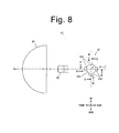
- Fig. 8 is a side view of the lighting unit (vehicle headlight) 31.
- the vehicle headlight 31 can include an LD 32, a light emitting member 33, a projector type lens 23, a driving member (such as an actuator) 35, and the like.
- the LD 32 is the semiconductor light emitting device as claimed, and for example, can emit blue laser light toward the light emitting member 33 disposed obliquely right and rearward with respect to the LD 32. Specifically, the LD 32 can irradiate any one of fluorescent portions 331A to 331D facing to the projector type lens 34 with the blue light, wherein the fluorescent portions 331A to 331D can be disposed on the peripheral surface of the light emitting member 33.
- the light emitting member 33 can function as a fluorescent member as a light distribution control member configured to form a plurality of light distribution patterns.
- the light emitting member 33 can include a cylindrical rotation member 330 extending in the right-to-left direction (width direction).
- the rotation member 330 can be configured to be rotatable around a rotation shaft 37 the end of which can be connected to the actuator 35 that can control the rotation angle thereof.
- the shape of the rotation member 330 is not limited to the cylinder, but any shape as long as it can be rotated.
- the four fluorescent portions 331A to 331D can be disposed on the peripheral surface of the rotation member 330 in the peripheral direction at every 90 degrees as a center angle.
- These fluorescent portions 331A to 331D can be formed from a fluorescent material that can receive the blue light emitted from the LD 32 to be excited thereby and emit yellow light. Accordingly, when the fluorescent portion 331 (331A to 331D are collectively referred to as 331) can receive the blue light, the blue light diffused by the fluorescent portion 331 (or diffusion material contained therein) and the yellow light emitted by the fluorescent portion 331 as a result of excitation can be mixed together. As a result of the additive color mixing, the resulting white color light can be emitted radially.
- the fluorescent portions 331 can function as a light emitting surface (or function as a pseudo light source). Accordingly, they can be prepared by simply applying a fluorescent material onto the corresponding surface of the rotation member. Examples of the fluorescent material for use in the fluorescent portions 331 include a YAG (Yttrium Aluminum Garnet) with a rare earth added, and various common fluorescent materials.
- YAG Yttrium Aluminum Garnet
- Figs. 9A, 9B, 9C, and 9D are views when viewed from arrow A, arrow B, arrow C and arrow D in Fig. 8 , respectively, and Fig. 10A, 10B, 10C, and 10D are cross-sectional views taken along line PO, line QO, line RO, and line SO in Fig. 8 , respectively. It should be noted that Figs. 9A to 9D are views when seen from the respective front sides.
- the four fluorescent portions 331A to 331D can be formed as a first fluorescent portion 331A to a fourth fluorescent portion 331D each having a different front shape (a shape of an image to be projected) when viewed from its front side.
- the first fluorescent portion 331A to fourth fluorescent portion 331D can be formed to be a different contour (a shape of an image to be projected) when viewed from its front side and provide similar figures to the respective shapes obtained by inverting the shapes of required light distribution patterns.
- the contour (shape to be projected) of the first fluorescent portion 331A can be a similar figure to the shape obtained by inverting the shape of a low-beam light distribution
- the contour (shape to be projected) of the second fluorescent portion 331B can be a similar figure to the shape obtained by inverting the shape of a high-beam light distribution
- the contour (shape to be projected) of the third fluorescent portion 331C can be a similar figure to the shape obtained by inverting the shape of a highway running light distribution
- the contour (shape to be projected) of the fourth fluorescent portion 331D can be a similar figure to the shape obtained by inverting the shape of an urban zone traveling light distribution.
- the first to fourth fluorescent portions 331A to 331D can each have a recess and/or a convex. This surface recess and/or convex can determine the luminance distribution of the light distribution pattern formed by the white light from each fluorescent portion 331.
- each fluorescent portion 331 can have a surface with a recess and/or a convex so that the blue light Lb from the LD 32 can impinge by a sharper angle on a portion of the surface from which higher density white light Lw is emitted to be brighter.
- the surface of each of the first to fourth fluorescent portions 331A to 331D can have a recess and/or a convex so that the blue light from the LD 32 can impinge by a sharper angle on a portion of the surface from which white light is emitted to form part of the light distribution pattern with higher luminance required.
- the recess and/or convex can be provided so that the surface of the first fluorescent portion 331A can correspond to the luminous intensity of the low-beam light distribution, the surface of the second fluorescent portion 331B can correspond to the luminous intensity of the high-beam light distribution, the surface of the third fluorescent portion 331C can correspond to the luminous intensity of the high-speed running light distribution, and the surface of the fourth fluorescent portion 331D can correspond to the luminous intensity of the urban zone traveling light distribution.
- the projector type lens 34 can be a plano-convex lens with a front convex surface and have an optical axis Ax in the front-to-rear direction, on which the light emission member 33 (rotation member 330) is positioned.
- the projector type lens 34 can be disposed in front of the fluorescent member 33.
- the projector type lens 34 can have a rear focal point positioned at or near the fluorescent portions 331. With this configuration, the white light emitted from the fluorescent portion 331 forward can be projected forward through the projector type lens 34 while the shape of the image of the fluorescent portion 331 is inverted vertically and horizontally by the projector type lens 34.
- Figs. 12A, 12B, 12C, and 12D are diagrams showing light distribution patterns that can be formed by the lighting unit (vehicle headlight) 31 when viewed from the vehicle side, respectively.
- Figs. 13A, 13B, 13C, and 13D are diagrams showing the light distribution patterns that can be formed by the lighting unit (vehicle headlight) 31 when viewed above, respectively.
- the blue light emitted from the LD 32 can be projected onto the fluorescent portion 331 facing to the projector type lens 34, and white light emitted from the fluorescent portion 331 by the color additive mixing of blue light and yellow light forward can be projected forward through the projector type lens 34 while the shape of the image of the fluorescent portion 331 is inverted vertically and horizontally by the projector type lens 34.
- the contour (shape of the image to be projected) of the first fluorescent portion 331A is inverted vertically and horizontally by the projector type lens 34 with the brightness distribution corresponding to the surface recess and/or convex of the first fluorescent member 331A. Accordingly, as shown in Figs.
- the low beam (passing-by beam) Pa can be projected in front of the vehicle with the light distribution pattern obtained by vertically and horizontally inverting the contour (the shape of the image to be projected) of the first fluorescent portion 331A and with the luminance distribution corresponding to the surface recess and/or convex of the first fluorescent portion 331A.
- the contour (shape of the image to be projected) of the second fluorescent portion 331B is inverted vertically and horizontally by the projector type lens 34 with the brightness distribution corresponding to the surface recess and/or convex of the second fluorescent portion 331B. Accordingly, as shown in Figs. 12B and 13B , the high beam Pb can be projected in front of the vehicle with the light distribution pattern obtained by vertically and horizontally inverting the contour (the shape of the image to be projected) of the second fluorescent portion 331B and with the luminance distribution corresponding to the surface recess and/or convex of the second fluorescent portion 331B.
- the third fluorescent portion 331C when the third fluorescent portion 331C is caused to face to the projector type lens 34 by the driving control of the actuator 35, the highway running beam Pc can be projected in front of the vehicle as shown in Figs. 12C and 13C .
- the fourth fluorescent portion 331D when the fourth fluorescent portion 331D is caused to face to the projector type lens 34 by the driving control of the actuator 35, the urban zone traveling beam Pd can be projected in front of the vehicle as shown in Figs. 12D and 13D .
- the light emitting member 33 (rotation member 330) is driven by the actuator 35 to rotate and thereby change the projected image by switching the fluorescent portions 331 that face to the projector type lens 34.
- the shape of light projected from the projector type lens 34 can be changed.
- a plurality of light distribution patterns can be formed only by rotating the rotation member 330 of the light emitting member (fluorescent member) 33 by a predetermined angle without shielding the light from the LD 32.
- each fluorescent portion 331 can have a recess and/or a convex so that the blue light from the LD 32 can impinge by a sharper angle on a portion of the surface from which white light is emitted to form part of the light distribution pattern with higher luminance required.
- a light distribution pattern with the luminance distribution corresponding to the surface recess and/or convex of the fluorescent portion 331 can be formed. This means a light distribution pattern with a desired luminance distribution can be formed simply by appropriately shaping the surface of the fluorescent portion 331.
- the semiconductor light emitting device of the present invention is a laser diode as one example, or it may be a light emitting diode. In view of light-gathering performance to the fluorescent portion, a laser diode is preferred. Furthermore, the light emitted from the LD may be collimated with respect to the fluorescent portion.
- the fluorescent portion may contain a diffusion material configured to diffuse the light emitted from the LD, and examples thereof include calcium carbonate, titanium oxide, alumina, and the like.
- a diffusion material configured to diffuse the light emitted from the LD
- examples thereof include calcium carbonate, titanium oxide, alumina, and the like.
- the fluorescent material and the diffusion material can be mixed together with a binder resin or the like, they are preferably integrated by sintering in terms of durability and heat resistance.
- the LD can emit blue light and the fluorescent portion can emit yellow light by the excitation with the blue light, but they are not limited thereto, and other combinations of color of excitation light and fluorescent material can be employed for emitting white light or other colored light.
- the excitation light is blue light and fluorescent materials emitting red light and green light respectively can be used.
- the excitation light is UV light and fluorescent materials emitting red light, green light, and blue light respectively can be used.
- the fluorescent member preferably does not contain a diffusion material.
- the dimension of the fluorescent portion is preferably as small as possible because a point light source is preferred, but too small dimension may hinder the processability and the handleability. In view of this, it may be sized in a range of 1 mm to 30 mm in height, width and depth directions.
- the fluorescent portion can change the brightness of light emitted therefrom by the density of the fluorescent material and/or the diffusion material constituting the fluorescent portion. For example, when the density at the center of the fluorescent portion is made high, the brightness thereat can be increased accordingly. In this manner, the luminance distribution of the desired light distribution pattern can be controlled by adjusting the density distribution of the fluorescent material and/or diffusion material of the fluorescent portion.
- the contour (the shape of the image to be projected) of the fluorescent portion/member can be varied continuously by the rotation or discontinuously set as in the above exemplary embodiments.
- the fluorescent member can be driven by the driving member to rotate continuously or intermittently, thereby freely providing required light distribution patterns.
- Examples of the driving member include a hydraulic actuator, a pneumatic actuator, a motor, and the like mechanism that can drive and control a rotating member.
Landscapes
- Engineering & Computer Science (AREA)
- General Engineering & Computer Science (AREA)
- Physics & Mathematics (AREA)
- Spectroscopy & Molecular Physics (AREA)
- Geometry (AREA)
- Optics & Photonics (AREA)
- Non-Portable Lighting Devices Or Systems Thereof (AREA)
Applications Claiming Priority (2)
| Application Number | Priority Date | Filing Date | Title |
|---|---|---|---|
| JP2010243070A JP5627992B2 (ja) | 2010-10-29 | 2010-10-29 | 灯具ユニット |
| JP2010250479A JP5571532B2 (ja) | 2010-11-09 | 2010-11-09 | 車両用前照灯 |
Publications (3)
| Publication Number | Publication Date |
|---|---|
| EP2447600A2 true EP2447600A2 (fr) | 2012-05-02 |
| EP2447600A3 EP2447600A3 (fr) | 2017-12-27 |
| EP2447600B1 EP2447600B1 (fr) | 2019-02-27 |
Family
ID=45540712
Family Applications (1)
| Application Number | Title | Priority Date | Filing Date |
|---|---|---|---|
| EP11008605.5A Active EP2447600B1 (fr) | 2010-10-29 | 2011-10-27 | Phare de véhicule |
Country Status (2)
| Country | Link |
|---|---|
| US (1) | US8702289B2 (fr) |
| EP (1) | EP2447600B1 (fr) |
Cited By (7)
| Publication number | Priority date | Publication date | Assignee | Title |
|---|---|---|---|---|
| AT512587A1 (de) * | 2012-03-12 | 2013-09-15 | Zizala Lichtsysteme Gmbh | Optikelement für einen Laser-Fahrzeugscheinwerfer sowie Lichtquellenmodul und Fahrzeugscheinwerfer |
| GB2504330A (en) * | 2012-07-26 | 2014-01-29 | Sharp Kk | Headlight system incorporating adaptive beam function |
| GB2504332A (en) * | 2012-07-26 | 2014-01-29 | Sharp Kk | Headlight system incorporating adaptive beam function |
| AT513916A3 (de) * | 2013-02-07 | 2014-09-15 | Zizala Lichtsysteme Gmbh | Scheinwerfer für ein Kraftfahrzeug und Verfahren zum Erzeugen einer Lichtverteilung |
| CN104595839A (zh) * | 2013-11-01 | 2015-05-06 | 丹阳市米可汽车零部件厂 | 车灯闪烁机构 |
| AT515375A1 (de) * | 2014-01-20 | 2015-08-15 | Zizala Lichtsysteme Gmbh | Lasereinheit für einen Fahrzeugscheinwerfer sowie Lasermodul |
| EP2541129A3 (fr) * | 2011-06-28 | 2018-04-18 | Sharp Kabushiki Kaisha | Dispositif d'éclairage et phare de véhicule |
Families Citing this family (4)
| Publication number | Priority date | Publication date | Assignee | Title |
|---|---|---|---|---|
| DE102013226639A1 (de) * | 2013-12-19 | 2015-06-25 | Osram Gmbh | Erzeugen eines Lichtabstrahlmusters in einem Fernfeld |
| DE112016002739B4 (de) * | 2015-06-16 | 2021-12-09 | Mitsubishi Electric Corporation | Scheinwerfervorrichtung und Beleuchtungsvorrichtung |
| CN110145720A (zh) * | 2019-06-14 | 2019-08-20 | 华域视觉科技(上海)有限公司 | 远近光一体的车灯模组 |
| CN112097155B (zh) * | 2020-08-31 | 2024-03-19 | 扬州吉山津田光电科技有限公司 | 一种防蓝光智能台灯及其智能控制方法 |
Citations (2)
| Publication number | Priority date | Publication date | Assignee | Title |
|---|---|---|---|---|
| JPH0447266B2 (fr) | 1986-10-03 | 1992-08-03 | Japan Aviation Electron | |
| US7165871B2 (en) | 2003-11-19 | 2007-01-23 | Koito Manufacturing Co., Ltd. | Lamp |
Family Cites Families (9)
| Publication number | Priority date | Publication date | Assignee | Title |
|---|---|---|---|---|
| JPH05337672A (ja) * | 1992-06-09 | 1993-12-21 | Fujitsu Ltd | レーザ反射ミラー |
| JP2005159178A (ja) * | 2003-11-27 | 2005-06-16 | Nichia Chem Ind Ltd | 発光素子およびそれを用いた光源装置 |
| JP4354435B2 (ja) * | 2005-07-13 | 2009-10-28 | 三菱電機株式会社 | 発光装置および照明装置 |
| JP4881255B2 (ja) * | 2007-08-13 | 2012-02-22 | 株式会社小糸製作所 | 車両用前照灯 |
| DE102008022795B4 (de) * | 2008-05-08 | 2020-01-09 | Osram Opto Semiconductors Gmbh | Kfz-Scheinwerfer |
| JP5266605B2 (ja) * | 2009-03-27 | 2013-08-21 | スタンレー電気株式会社 | 車両用灯具 |
| JP2011065979A (ja) * | 2009-08-18 | 2011-03-31 | Sharp Corp | 光源装置 |
| JP4991001B2 (ja) * | 2009-12-28 | 2012-08-01 | シャープ株式会社 | 照明装置 |
| US9890929B2 (en) * | 2010-06-22 | 2018-02-13 | Osram Gmbh | Polyhedron, rotational arrangements, light source arrangements, a light source device, a lighting device, a three-dimensional body and projectors |
-
2011
- 2011-10-27 EP EP11008605.5A patent/EP2447600B1/fr active Active
- 2011-10-31 US US13/286,203 patent/US8702289B2/en not_active Expired - Fee Related
Patent Citations (2)
| Publication number | Priority date | Publication date | Assignee | Title |
|---|---|---|---|---|
| JPH0447266B2 (fr) | 1986-10-03 | 1992-08-03 | Japan Aviation Electron | |
| US7165871B2 (en) | 2003-11-19 | 2007-01-23 | Koito Manufacturing Co., Ltd. | Lamp |
Cited By (13)
| Publication number | Priority date | Publication date | Assignee | Title |
|---|---|---|---|---|
| EP2541129A3 (fr) * | 2011-06-28 | 2018-04-18 | Sharp Kabushiki Kaisha | Dispositif d'éclairage et phare de véhicule |
| AT512587A1 (de) * | 2012-03-12 | 2013-09-15 | Zizala Lichtsysteme Gmbh | Optikelement für einen Laser-Fahrzeugscheinwerfer sowie Lichtquellenmodul und Fahrzeugscheinwerfer |
| AT512587B1 (de) * | 2012-03-12 | 2013-11-15 | Zizala Lichtsysteme Gmbh | Optikelement für einen Laser-Fahrzeugscheinwerfer sowie Lichtquellenmodul und Fahrzeugscheinwerfer |
| US9845932B2 (en) | 2012-03-12 | 2017-12-19 | Zkw Group Gmbh | Optical element for a laser vehicle headlight |
| US9347635B2 (en) | 2012-07-26 | 2016-05-24 | Sharp Kabushiki Kaisha | Headlight system incorporating adaptive beam function |
| GB2504332A (en) * | 2012-07-26 | 2014-01-29 | Sharp Kk | Headlight system incorporating adaptive beam function |
| GB2504330A (en) * | 2012-07-26 | 2014-01-29 | Sharp Kk | Headlight system incorporating adaptive beam function |
| AT513916B1 (de) * | 2013-02-07 | 2015-04-15 | Zizala Lichtsysteme Gmbh | Scheinwerfer für ein Kraftfahrzeug und Verfahren zum Erzeugen einer Lichtverteilung |
| AT513916A3 (de) * | 2013-02-07 | 2014-09-15 | Zizala Lichtsysteme Gmbh | Scheinwerfer für ein Kraftfahrzeug und Verfahren zum Erzeugen einer Lichtverteilung |
| CN104595839A (zh) * | 2013-11-01 | 2015-05-06 | 丹阳市米可汽车零部件厂 | 车灯闪烁机构 |
| AT515375A1 (de) * | 2014-01-20 | 2015-08-15 | Zizala Lichtsysteme Gmbh | Lasereinheit für einen Fahrzeugscheinwerfer sowie Lasermodul |
| AT515375B1 (de) * | 2014-01-20 | 2016-03-15 | Zizala Lichtsysteme Gmbh | Lasereinheit für einen Fahrzeugscheinwerfer sowie Lasermodul |
| US10131268B2 (en) | 2014-01-20 | 2018-11-20 | Zkw Group Gmbh | Laser unit for a vehicle headlight |
Also Published As
| Publication number | Publication date |
|---|---|
| EP2447600B1 (fr) | 2019-02-27 |
| US20120140507A1 (en) | 2012-06-07 |
| US8702289B2 (en) | 2014-04-22 |
| EP2447600A3 (fr) | 2017-12-27 |
Similar Documents
| Publication | Publication Date | Title |
|---|---|---|
| EP2447600B1 (fr) | Phare de véhicule | |
| CN109073188B (zh) | 车辆用灯具、车辆用灯具控制系统以及具有这些装置的车辆 | |
| JP4933434B2 (ja) | 非対称コリメータを備えるledコリメータ素子 | |
| EP2487407B1 (fr) | Dispositif d'éclairage de véhicule | |
| JP6509480B2 (ja) | 照明装置 | |
| JP5859631B2 (ja) | 投光装置、および当該投光装置を備えた車両用前照灯 | |
| JP5550796B2 (ja) | 前照灯用光源および前照灯 | |
| JP5950385B2 (ja) | 車輌用前照灯 | |
| JP2005063706A (ja) | 車両前照灯用光源装置及び車両前照灯 | |
| JP7351225B2 (ja) | 車両用灯具 | |
| WO2016162921A1 (fr) | Source de lumière de phare et phare | |
| JP2012109209A (ja) | 発光装置、車両用前照灯、照明装置、及び車両 | |
| JP2008041271A (ja) | 車両前照灯 | |
| JP6680537B2 (ja) | 光学ユニットおよび車両用灯具 | |
| JP6445441B2 (ja) | 光学ユニット | |
| JP2013191325A (ja) | 照明装置および車両用前照灯 | |
| JP5033530B2 (ja) | 車両用灯具の光源ユニット | |
| CN112747287A (zh) | 产生弓形光分布的照明装置 | |
| JP2005259532A (ja) | 車両用灯具ユニット | |
| JP2007234562A (ja) | 車両用前照灯の灯具ユニット | |
| JP6022176B2 (ja) | 発光装置、照明装置および車両用前照灯 | |
| JP2019096486A (ja) | 車両用灯具 | |
| JP5627992B2 (ja) | 灯具ユニット | |
| JP4158140B2 (ja) | 車両用灯具 | |
| JP5266607B2 (ja) | 車両前照灯 |
Legal Events
| Date | Code | Title | Description |
|---|---|---|---|
| PUAI | Public reference made under article 153(3) epc to a published international application that has entered the european phase |
Free format text: ORIGINAL CODE: 0009012 |
|
| AK | Designated contracting states |
Kind code of ref document: A2 Designated state(s): AL AT BE BG CH CY CZ DE DK EE ES FI FR GB GR HR HU IE IS IT LI LT LU LV MC MK MT NL NO PL PT RO RS SE SI SK SM TR |
|
| AX | Request for extension of the european patent |
Extension state: BA ME |
|
| PUAL | Search report despatched |
Free format text: ORIGINAL CODE: 0009013 |
|
| AK | Designated contracting states |
Kind code of ref document: A3 Designated state(s): AL AT BE BG CH CY CZ DE DK EE ES FI FR GB GR HR HU IE IS IT LI LT LU LV MC MK MT NL NO PL PT RO RS SE SI SK SM TR |
|
| AX | Request for extension of the european patent |
Extension state: BA ME |
|
| RIC1 | Information provided on ipc code assigned before grant |
Ipc: G02B 26/08 20060101ALI20171122BHEP Ipc: F21S 8/12 20060101AFI20171122BHEP Ipc: F21S 8/10 20060101ALI20171122BHEP Ipc: F21W 101/02 20060101ALN20171122BHEP Ipc: F21V 14/08 20060101ALI20171122BHEP Ipc: F21V 9/16 20060101ALI20171122BHEP |
|
| STAA | Information on the status of an ep patent application or granted ep patent |
Free format text: STATUS: REQUEST FOR EXAMINATION WAS MADE |
|
| REG | Reference to a national code |
Ref country code: DE Ref legal event code: R079 Ref document number: 602011056528 Country of ref document: DE Free format text: PREVIOUS MAIN CLASS: F21S0008120000 Ipc: F21S0041190000 |
|
| 17P | Request for examination filed |
Effective date: 20180627 |
|
| RBV | Designated contracting states (corrected) |
Designated state(s): AL AT BE BG CH CY CZ DE DK EE ES FI FR GB GR HR HU IE IS IT LI LT LU LV MC MK MT NL NO PL PT RO RS SE SI SK SM TR |
|
| RIC1 | Information provided on ipc code assigned before grant |
Ipc: F21W 102/13 20180101ALN20180718BHEP Ipc: F21S 41/14 20180101ALI20180718BHEP Ipc: F21S 41/32 20180101ALI20180718BHEP Ipc: F21S 41/698 20180101ALI20180718BHEP Ipc: F21S 41/255 20180101ALI20180718BHEP Ipc: F21S 41/67 20180101ALI20180718BHEP Ipc: F21V 9/30 20180101ALI20180718BHEP Ipc: F21V 14/08 20060101ALI20180718BHEP Ipc: F21S 41/173 20180101ALI20180718BHEP Ipc: F21S 41/657 20180101ALI20180718BHEP Ipc: F21S 41/147 20180101ALI20180718BHEP Ipc: F21S 41/16 20180101ALI20180718BHEP Ipc: G02B 26/08 20060101ALI20180718BHEP Ipc: F21S 41/19 20180101AFI20180718BHEP |
|
| GRAP | Despatch of communication of intention to grant a patent |
Free format text: ORIGINAL CODE: EPIDOSNIGR1 |
|
| STAA | Information on the status of an ep patent application or granted ep patent |
Free format text: STATUS: GRANT OF PATENT IS INTENDED |
|
| INTG | Intention to grant announced |
Effective date: 20180918 |
|
| GRAS | Grant fee paid |
Free format text: ORIGINAL CODE: EPIDOSNIGR3 |
|
| GRAA | (expected) grant |
Free format text: ORIGINAL CODE: 0009210 |
|
| STAA | Information on the status of an ep patent application or granted ep patent |
Free format text: STATUS: THE PATENT HAS BEEN GRANTED |
|
| AK | Designated contracting states |
Kind code of ref document: B1 Designated state(s): AL AT BE BG CH CY CZ DE DK EE ES FI FR GB GR HR HU IE IS IT LI LT LU LV MC MK MT NL NO PL PT RO RS SE SI SK SM TR |
|
| REG | Reference to a national code |
Ref country code: GB Ref legal event code: FG4D |
|
| REG | Reference to a national code |
Ref country code: CH Ref legal event code: EP |
|
| REG | Reference to a national code |
Ref country code: AT Ref legal event code: REF Ref document number: 1101880 Country of ref document: AT Kind code of ref document: T Effective date: 20190315 |
|
| REG | Reference to a national code |
Ref country code: IE Ref legal event code: FG4D |
|
| REG | Reference to a national code |
Ref country code: DE Ref legal event code: R096 Ref document number: 602011056528 Country of ref document: DE |
|
| REG | Reference to a national code |
Ref country code: NL Ref legal event code: MP Effective date: 20190227 |
|
| REG | Reference to a national code |
Ref country code: LT Ref legal event code: MG4D |
|
| PG25 | Lapsed in a contracting state [announced via postgrant information from national office to epo] |
Ref country code: PT Free format text: LAPSE BECAUSE OF FAILURE TO SUBMIT A TRANSLATION OF THE DESCRIPTION OR TO PAY THE FEE WITHIN THE PRESCRIBED TIME-LIMIT Effective date: 20190627 Ref country code: LT Free format text: LAPSE BECAUSE OF FAILURE TO SUBMIT A TRANSLATION OF THE DESCRIPTION OR TO PAY THE FEE WITHIN THE PRESCRIBED TIME-LIMIT Effective date: 20190227 Ref country code: NL Free format text: LAPSE BECAUSE OF FAILURE TO SUBMIT A TRANSLATION OF THE DESCRIPTION OR TO PAY THE FEE WITHIN THE PRESCRIBED TIME-LIMIT Effective date: 20190227 Ref country code: FI Free format text: LAPSE BECAUSE OF FAILURE TO SUBMIT A TRANSLATION OF THE DESCRIPTION OR TO PAY THE FEE WITHIN THE PRESCRIBED TIME-LIMIT Effective date: 20190227 Ref country code: NO Free format text: LAPSE BECAUSE OF FAILURE TO SUBMIT A TRANSLATION OF THE DESCRIPTION OR TO PAY THE FEE WITHIN THE PRESCRIBED TIME-LIMIT Effective date: 20190527 Ref country code: SE Free format text: LAPSE BECAUSE OF FAILURE TO SUBMIT A TRANSLATION OF THE DESCRIPTION OR TO PAY THE FEE WITHIN THE PRESCRIBED TIME-LIMIT Effective date: 20190227 |
|
| PG25 | Lapsed in a contracting state [announced via postgrant information from national office to epo] |
Ref country code: BG Free format text: LAPSE BECAUSE OF FAILURE TO SUBMIT A TRANSLATION OF THE DESCRIPTION OR TO PAY THE FEE WITHIN THE PRESCRIBED TIME-LIMIT Effective date: 20190527 Ref country code: IS Free format text: LAPSE BECAUSE OF FAILURE TO SUBMIT A TRANSLATION OF THE DESCRIPTION OR TO PAY THE FEE WITHIN THE PRESCRIBED TIME-LIMIT Effective date: 20190627 Ref country code: GR Free format text: LAPSE BECAUSE OF FAILURE TO SUBMIT A TRANSLATION OF THE DESCRIPTION OR TO PAY THE FEE WITHIN THE PRESCRIBED TIME-LIMIT Effective date: 20190528 Ref country code: RS Free format text: LAPSE BECAUSE OF FAILURE TO SUBMIT A TRANSLATION OF THE DESCRIPTION OR TO PAY THE FEE WITHIN THE PRESCRIBED TIME-LIMIT Effective date: 20190227 Ref country code: LV Free format text: LAPSE BECAUSE OF FAILURE TO SUBMIT A TRANSLATION OF THE DESCRIPTION OR TO PAY THE FEE WITHIN THE PRESCRIBED TIME-LIMIT Effective date: 20190227 Ref country code: HR Free format text: LAPSE BECAUSE OF FAILURE TO SUBMIT A TRANSLATION OF THE DESCRIPTION OR TO PAY THE FEE WITHIN THE PRESCRIBED TIME-LIMIT Effective date: 20190227 |
|
| REG | Reference to a national code |
Ref country code: AT Ref legal event code: MK05 Ref document number: 1101880 Country of ref document: AT Kind code of ref document: T Effective date: 20190227 |
|
| PG25 | Lapsed in a contracting state [announced via postgrant information from national office to epo] |
Ref country code: RO Free format text: LAPSE BECAUSE OF FAILURE TO SUBMIT A TRANSLATION OF THE DESCRIPTION OR TO PAY THE FEE WITHIN THE PRESCRIBED TIME-LIMIT Effective date: 20190227 Ref country code: IT Free format text: LAPSE BECAUSE OF FAILURE TO SUBMIT A TRANSLATION OF THE DESCRIPTION OR TO PAY THE FEE WITHIN THE PRESCRIBED TIME-LIMIT Effective date: 20190227 Ref country code: SK Free format text: LAPSE BECAUSE OF FAILURE TO SUBMIT A TRANSLATION OF THE DESCRIPTION OR TO PAY THE FEE WITHIN THE PRESCRIBED TIME-LIMIT Effective date: 20190227 Ref country code: CZ Free format text: LAPSE BECAUSE OF FAILURE TO SUBMIT A TRANSLATION OF THE DESCRIPTION OR TO PAY THE FEE WITHIN THE PRESCRIBED TIME-LIMIT Effective date: 20190227 Ref country code: AL Free format text: LAPSE BECAUSE OF FAILURE TO SUBMIT A TRANSLATION OF THE DESCRIPTION OR TO PAY THE FEE WITHIN THE PRESCRIBED TIME-LIMIT Effective date: 20190227 Ref country code: DK Free format text: LAPSE BECAUSE OF FAILURE TO SUBMIT A TRANSLATION OF THE DESCRIPTION OR TO PAY THE FEE WITHIN THE PRESCRIBED TIME-LIMIT Effective date: 20190227 Ref country code: ES Free format text: LAPSE BECAUSE OF FAILURE TO SUBMIT A TRANSLATION OF THE DESCRIPTION OR TO PAY THE FEE WITHIN THE PRESCRIBED TIME-LIMIT Effective date: 20190227 Ref country code: EE Free format text: LAPSE BECAUSE OF FAILURE TO SUBMIT A TRANSLATION OF THE DESCRIPTION OR TO PAY THE FEE WITHIN THE PRESCRIBED TIME-LIMIT Effective date: 20190227 |
|
| REG | Reference to a national code |
Ref country code: DE Ref legal event code: R097 Ref document number: 602011056528 Country of ref document: DE |
|
| PG25 | Lapsed in a contracting state [announced via postgrant information from national office to epo] |
Ref country code: SM Free format text: LAPSE BECAUSE OF FAILURE TO SUBMIT A TRANSLATION OF THE DESCRIPTION OR TO PAY THE FEE WITHIN THE PRESCRIBED TIME-LIMIT Effective date: 20190227 Ref country code: PL Free format text: LAPSE BECAUSE OF FAILURE TO SUBMIT A TRANSLATION OF THE DESCRIPTION OR TO PAY THE FEE WITHIN THE PRESCRIBED TIME-LIMIT Effective date: 20190227 |
|
| PG25 | Lapsed in a contracting state [announced via postgrant information from national office to epo] |
Ref country code: AT Free format text: LAPSE BECAUSE OF FAILURE TO SUBMIT A TRANSLATION OF THE DESCRIPTION OR TO PAY THE FEE WITHIN THE PRESCRIBED TIME-LIMIT Effective date: 20190227 |
|
| PLBE | No opposition filed within time limit |
Free format text: ORIGINAL CODE: 0009261 |
|
| STAA | Information on the status of an ep patent application or granted ep patent |
Free format text: STATUS: NO OPPOSITION FILED WITHIN TIME LIMIT |
|
| 26N | No opposition filed |
Effective date: 20191128 |
|
| PG25 | Lapsed in a contracting state [announced via postgrant information from national office to epo] |
Ref country code: SI Free format text: LAPSE BECAUSE OF FAILURE TO SUBMIT A TRANSLATION OF THE DESCRIPTION OR TO PAY THE FEE WITHIN THE PRESCRIBED TIME-LIMIT Effective date: 20190227 |
|
| PG25 | Lapsed in a contracting state [announced via postgrant information from national office to epo] |
Ref country code: TR Free format text: LAPSE BECAUSE OF FAILURE TO SUBMIT A TRANSLATION OF THE DESCRIPTION OR TO PAY THE FEE WITHIN THE PRESCRIBED TIME-LIMIT Effective date: 20190227 |
|
| PG25 | Lapsed in a contracting state [announced via postgrant information from national office to epo] |
Ref country code: MC Free format text: LAPSE BECAUSE OF FAILURE TO SUBMIT A TRANSLATION OF THE DESCRIPTION OR TO PAY THE FEE WITHIN THE PRESCRIBED TIME-LIMIT Effective date: 20190227 |
|
| REG | Reference to a national code |
Ref country code: CH Ref legal event code: PL |
|
| PG25 | Lapsed in a contracting state [announced via postgrant information from national office to epo] |
Ref country code: LI Free format text: LAPSE BECAUSE OF NON-PAYMENT OF DUE FEES Effective date: 20191031 Ref country code: CH Free format text: LAPSE BECAUSE OF NON-PAYMENT OF DUE FEES Effective date: 20191031 Ref country code: LU Free format text: LAPSE BECAUSE OF NON-PAYMENT OF DUE FEES Effective date: 20191027 |
|
| REG | Reference to a national code |
Ref country code: BE Ref legal event code: MM Effective date: 20191031 |
|
| PG25 | Lapsed in a contracting state [announced via postgrant information from national office to epo] |
Ref country code: BE Free format text: LAPSE BECAUSE OF NON-PAYMENT OF DUE FEES Effective date: 20191031 |
|
| PG25 | Lapsed in a contracting state [announced via postgrant information from national office to epo] |
Ref country code: IE Free format text: LAPSE BECAUSE OF NON-PAYMENT OF DUE FEES Effective date: 20191027 |
|
| PG25 | Lapsed in a contracting state [announced via postgrant information from national office to epo] |
Ref country code: CY Free format text: LAPSE BECAUSE OF FAILURE TO SUBMIT A TRANSLATION OF THE DESCRIPTION OR TO PAY THE FEE WITHIN THE PRESCRIBED TIME-LIMIT Effective date: 20190227 |
|
| PG25 | Lapsed in a contracting state [announced via postgrant information from national office to epo] |
Ref country code: MT Free format text: LAPSE BECAUSE OF FAILURE TO SUBMIT A TRANSLATION OF THE DESCRIPTION OR TO PAY THE FEE WITHIN THE PRESCRIBED TIME-LIMIT Effective date: 20190227 Ref country code: HU Free format text: LAPSE BECAUSE OF FAILURE TO SUBMIT A TRANSLATION OF THE DESCRIPTION OR TO PAY THE FEE WITHIN THE PRESCRIBED TIME-LIMIT; INVALID AB INITIO Effective date: 20111027 |
|
| PG25 | Lapsed in a contracting state [announced via postgrant information from national office to epo] |
Ref country code: MK Free format text: LAPSE BECAUSE OF FAILURE TO SUBMIT A TRANSLATION OF THE DESCRIPTION OR TO PAY THE FEE WITHIN THE PRESCRIBED TIME-LIMIT Effective date: 20190227 |
|
| PGFP | Annual fee paid to national office [announced via postgrant information from national office to epo] |
Ref country code: GB Payment date: 20230907 Year of fee payment: 13 |
|
| PGFP | Annual fee paid to national office [announced via postgrant information from national office to epo] |
Ref country code: FR Payment date: 20230911 Year of fee payment: 13 |
|
| PGFP | Annual fee paid to national office [announced via postgrant information from national office to epo] |
Ref country code: DE Payment date: 20230830 Year of fee payment: 13 |