EP2444584A2 - Rolltor, sowie Torsäule für ein Rolltor - Google Patents
Rolltor, sowie Torsäule für ein Rolltor Download PDFInfo
- Publication number
- EP2444584A2 EP2444584A2 EP11008405A EP11008405A EP2444584A2 EP 2444584 A2 EP2444584 A2 EP 2444584A2 EP 11008405 A EP11008405 A EP 11008405A EP 11008405 A EP11008405 A EP 11008405A EP 2444584 A2 EP2444584 A2 EP 2444584A2
- Authority
- EP
- European Patent Office
- Prior art keywords
- door
- wall
- gate
- column
- guide slot
- Prior art date
- Legal status (The legal status is an assumption and is not a legal conclusion. Google has not performed a legal analysis and makes no representation as to the accuracy of the status listed.)
- Granted
Links
Images


Classifications
-
- E—FIXED CONSTRUCTIONS
- E06—DOORS, WINDOWS, SHUTTERS, OR ROLLER BLINDS IN GENERAL; LADDERS
- E06B—FIXED OR MOVABLE CLOSURES FOR OPENINGS IN BUILDINGS, VEHICLES, FENCES OR LIKE ENCLOSURES IN GENERAL, e.g. DOORS, WINDOWS, BLINDS, GATES
- E06B9/00—Screening or protective devices for wall or similar openings, with or without operating or securing mechanisms; Closures of similar construction
- E06B9/56—Operating, guiding or securing devices or arrangements for roll-type closures; Spring drums; Tape drums; Counterweighting arrangements therefor
- E06B9/58—Guiding devices
-
- E—FIXED CONSTRUCTIONS
- E06—DOORS, WINDOWS, SHUTTERS, OR ROLLER BLINDS IN GENERAL; LADDERS
- E06B—FIXED OR MOVABLE CLOSURES FOR OPENINGS IN BUILDINGS, VEHICLES, FENCES OR LIKE ENCLOSURES IN GENERAL, e.g. DOORS, WINDOWS, BLINDS, GATES
- E06B9/00—Screening or protective devices for wall or similar openings, with or without operating or securing mechanisms; Closures of similar construction
- E06B9/02—Shutters, movable grilles, or other safety closing devices, e.g. against burglary
- E06B9/08—Roll-type closures
- E06B9/11—Roller shutters
- E06B9/13—Roller shutters with closing members of one piece, e.g. of corrugated sheet metal
-
- E—FIXED CONSTRUCTIONS
- E06—DOORS, WINDOWS, SHUTTERS, OR ROLLER BLINDS IN GENERAL; LADDERS
- E06B—FIXED OR MOVABLE CLOSURES FOR OPENINGS IN BUILDINGS, VEHICLES, FENCES OR LIKE ENCLOSURES IN GENERAL, e.g. DOORS, WINDOWS, BLINDS, GATES
- E06B9/00—Screening or protective devices for wall or similar openings, with or without operating or securing mechanisms; Closures of similar construction
- E06B9/56—Operating, guiding or securing devices or arrangements for roll-type closures; Spring drums; Tape drums; Counterweighting arrangements therefor
- E06B9/58—Guiding devices
- E06B2009/585—Emergency release to prevent damage of shutter or guiding device
Definitions
- the invention relates to a roller shutter, in particular a high-speed roller shutter, with a flexible door curtain according to the preamble of claim 1 and a gate column for a roller door of this type.
- the door curtain In order to bring the drawn-out edge strips of the door curtain and the end parts of the end strip in their desired position, the door curtain must be pulled together with closing bar upwards, in a position above the ends of the guides so that the edge strips can be threaded back into the guides. During this Moving upward, the edge strips of the door curtain or lateral parts of the finishing strip of the door curtain grind on the outside of the goal posts or on the soffits of the wall opening. This additional load is present in the event of hair lifting by the mass of the end bar and also in the case of a curtain lift with tensioning cables.
- the object of the invention is to provide a rolling shutter with simple means and low structural complexity, which does not have the aforementioned disadvantages or in which the disadvantages are substantially reduced.
- At least one vertically oriented expansion channel is arranged at least at one of its gate columns sideways of the guide slot in this new roller door; preferably on both sides of the guide slot ever a relaxation trough.
- At least one substantially vertically oriented expansion channel is provided in the two door columns.
- the door curtain In and through a crash, the door curtain is pushed out of his leadership level along with its end bar from the guides. In the new roller door it comes because of the erfdindungsissue and preferably immediately adjacent to the guide slot provided relaxation channel at each gate column to no jamming of the door curtain, in particular its edge strips between the front of the Torkla / -en or between the end strip and the reveal of the wall opening. There is also no constant bending and tension of the side edges of the Door curtain between the soffits of the wall / door opening, as is otherwise the case in a crash with roller doors according to the prior art.
- the expansion channel located on the wall side of the guide slot is formed by a portion of the lateral surface of the door column and a portion of the wall located laterally of the soffit of the wall opening.
- each expansion channel is integral with the front door facing the door curtain.
- each expansion channel is located directly next to the guide slot.
- each relaxation channel has a sliding surface leading to the guide slot.
- the core of the invention is also applicable to already in operation shutters.
- a novel gate column for a roller shutter in particular / primarily a high-speed roll-up door, provided with a flexible door hanger, which can be exchanged for the existing gate columns.
- This pillar column has at least one facing the door curtain front and an angle thereto arranged, retreating wall side, there at least fasteners.
- Starting from a front plane belonging to the front, according to the invention at least the wall-side portion of the front of the curtain fleeing and reset to form a, preferably obliquely directed sliding surface to form the at least one relaxation channel, which is formed here together with the wall portion at the wall opening.
- the side facing away from the wall, opposite lateral portion of the front with respect to the front plane also to form a, preferably obliquely directed sliding surface for forming the second expansion channel at this gate column.
- the guide slot facing portions of the front from the front plane from escaping guide surfaces defining a guide funnel, which is integral with the guide slot and forms its input.
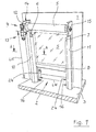
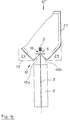
- the new roller door 4 according to the invention is in the FIG. 1 shown in a perspective view.
- a floor 3 On a floor 3 is a portion of a wall 1 with a wall opening 2.
- a roller shutter 4 On one side of the wall 1 is a roller shutter 4, here in self-supporting design, arranged at the wall opening 2.
- Sideways of the soffits of the wall opening 2 are the torso columns 10 and 11 of the roll-up door 4.
- a winding shaft 12 in bearings 14, 15 is arranged rotatably and drivable.
- the drive 13 here consists of a motor, a transmission and a control unit.
- the control unit together with its operating element is arranged at normal working height in one of the door columns 10 and 11, respectively. A duplicate of the control unit is then still on the other side of the wall opening 2 next to selbiger 2.
- a cover strip 8 is provided.
- the horizontal distance between the respective front plane FE of the gate columns 10 and 11 corresponds approximately to the length L between the sides 8a, 8b of the end strip 8, wherein on both sides of the end strip 8 to the respective front plane FE through a gap is formed, so that upon movement of the door curtain 5 and thus the end strip 8 no jamming of the end strip 8 between the columns 10, 11 takes place.
- the distance between the gate columns 10, 11 is also chosen so that the inside width LW of the wall opening / door opening 2 can be fully utilized. For one end position "gate open" the door curtain 5 is raised so far and rolled up on the winding shaft until the lower edge of the end strip 8 above the clear height LH of the wall opening / gate opening 2 is.
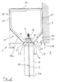
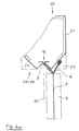
- FIG. 2 is the roller shutter 4 after FIG. 1 shown in a cross section at the section line AA.
- the illustration is a partial cross-section, this is sufficient for explanation, since the two gate columns 10, 11 and the environment around selbige same.
- the torso column 10 at a distance opposite torso column 11 is executed only a mirror image, so that the explanations to the features of the invention can be made on a partial section.
- the gate column 10 shown here has a front 18, a back 19, a free side 20 and a wall side 21, with the gate column 10 is disposed on the wall 1 near the wall opening 2 so that the formed by the front 18 front plane FE of Gate column 10 with a small distance L1 sideways the reveal of the wall opening 2 is.
- a guide slot 16 is provided in the front side 18 of the door pillar 10 for guiding the edge strips 6, 7 of the door curtain 5 in a guide plane BE.
- vertically directed relaxation channels 24 are provided here laterally of the guide slot 16 in the direction of the body of the column 10, respectively for freely receiving one of the edge strips 6 or 7 or sections thereof after a said crash So, to relax the tensioned during the crash Torbehanges, as well as to lead and guide them when they return to their normal position.
- the at least one guide channel 24 is formed with a wall section 1 a of the wall 1 and an inclined surface 18 d of the body of the column 10.
- the relaxation trough 24 arranged on the other side of the guide slot 16 is defined at least by a bevel 18c of the body of the pillar column 10 extending from the front 18 and towards the free side 20, so that from the front plane FE and from the end strip 8 of the door curtain 5 facing away, which is formed at the gate column 10 required clearance, to the further details will be explained later.
- each guide slot 16 has a guide strip 17 in the region of their smallest distance from one another.
- each guide strip 17 is formed by bending the end sections of the guide surface 18a or 18b.
- the guide slot 16 which generates by this configuration, compared to known roller doors, a lower friction in the movement of the door curtain 5 at the edge strips 6 and 7 respectively.
- transition from the sliding surface 18 c or 18 d to the guide surface 18 a and 18 b is made in the embodiment shown by bending in the relevant component of the gate column 10. This fold is also such that dome 22, so in each case a dome 22, are formed, which cause a gentle sliding of the edge strips 6 and 7 in the process "reversing" or upon retrieval in the guide slot 16 in a crash.
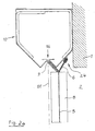
- FIG. 2a is the roller door after FIG. 2 shown in a situation after a crash on the curtain 5.
- the door curtain 5 has been pressed together with end strip 8 from the guide level BE in the direction of wall opening 2 from the guides 16.
- the tensioning cable 9 provided for this door to the door tension tension, which engages usually at the respective edge region of the end strip 8, is also pulled out of the guide slot in such a crash with a partial section.
- With the guide surface 8a and 8b of the guide funnel 23 together with the dome 22 a gentle, friction-moderate guidance of this section of the tensioning cable 9 is also guaranteed.
- FIGS. 6 Such a situation according to the prior art is in the FIGS. 6 , especially in FIGS. 6b and 6c shown.
- novel roller shutter 4 according to the invention With the novel roller shutter 4 according to the invention, such additional loading of the door curtain 5 and its parts, which cause increased wear or even damage to the door curtain 5 is avoided with little effort.
- roller door 4 according to the invention is also shown in a partial cross-section.
- the roller shutter 4 is installed with its door column 10 in an existing next to the reveal of the wall opening 2 wall niche 1 b.
- This illustration is intended to make it clear that the new roller shutter door can be used for closing and opening wall openings / door openings of the most varied types.
- the situation shown in FIG. 3 is similar to the situation FIG. 2 and the situation in FIG. 3a according to the situation FIG. 2a so that no repetitions are made here.
- the reference numbers used in principle throughout the description same meaning, even if they are not explicitly mentioned in the description of the individual figures.
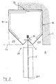
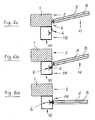
- FIG. 4 and 4a is a Torkladle 10 'shown for subsequent installation on already in operation shutters in a partial cross-section.
- This gate column 10 ' is at least formed by two legs arranged substantially at right angles to each other, a front 18 and a wall side 21. Starting from the front plane FE of the front 18, the outer wall sections of the front 18 escape, so that on both sides of a guide slot 16 in the body of the column 10 'each a relaxation channel 24 is formed.
- This gate column 10 ' is placed and fixed with its wall side 21 on a wall at the same location next to the wall opening for replacement with the already in operation gate column.
- the opposite gate column is constructed in mirror image, it is not shown here because it is similar.
- FIG. 4a is also a situation after a crash shown.
- the pulled out of the guide slot 16 edge strip 6 of the door curtain 5 is located substantially in the relaxation channel 24 and is, within said limits, free to move the process "reversing".
- the door curtain 5 without being subjected to damage by strong deflection and friction on edges and wall surfaces, can be moved upwards to a position in which the threading into its desired position, ie in the guide plane BE occurs; this is in the extreme case a position above the end of the gate columns.
- profile cross sections are shown, which can be used in this gate column 10 'and also in the gate columns 10 and 11 of the roller door 4 described above.
- Which profile / profile cross-section is used depends on the specific installation conditions and task of the respective application. Such conditions can be, for example, production costs / material costs, special stability conditions or spatial conditions.
Landscapes
- Engineering & Computer Science (AREA)
- Structural Engineering (AREA)
- Architecture (AREA)
- Civil Engineering (AREA)
- Operating, Guiding And Securing Of Roll- Type Closing Members (AREA)
Abstract
Description
- Die Erfindung betrifft ein Rolltor, insbesondere ein schnell laufendes Rolltor, mit einem flexiblen Torbehang nach dem Oberbegriff des Anspruches 1 und eine Torsäule für ein Rolltor dieser Gattung.
- Um Schäden durch Kollision gering zu halten oder auszuschließen ist es bei Rolltoren nach dem Stand der Technik bekannt, eine Teilung der den Torbehang versteifenden und führenden Abschlussleiste vorzusehen. Zudem können, wie bei einem Rolltor nach der
DE 40 07 280 C2 , die Teile der Abschlussleiste, insbesondere deren Endteile aus einem Werkstoff hoher Elastizität bestehen, so dass im Falle einer Kollision bei Überschreitung einer vorbestimmten Querkraft die Endteile unter elastischer Verformung aus den Führungen austreten. - Um die heraus gezogenen Randstreifen des Torbehanges sowie die Endteile der Abschlussleiste in ihre Soll-Lage zu bringen, muss der Torbehang nebst Abschlussleiste nach oben, in eine Position oberhalb der Enden der Führungen gezogen werden, damit die Randstreifen wieder in die Führungen eingefädelt werden können. Während dieser Bewegung nach oben schleifen die Randstreifen des Torbehanges bzw. seitliche Teile der Abschlussleiste des Torbehanges außen an den Torpfosten bzw. an den Leibungen der Wandöffnung. Diese zusätzliche Belastung ist bei Behangstraffung durch die Masse der Abschlussleiste und auch bei einer Behangstraffung mittels Spannseilen vorhanden. Aufgabe der Erfindung ist es, mit einfachen Mittel und geringem baulichen Aufwand ein Rolltor zu schaffen, welches die vorgenannten Nachteile nicht aufweist bzw. bei dem die Nachteile wesentlich gemindert sind.
- Die Aufgabe wird gelöst durch ein Rolltor mit den Merkmalen des Patentanspruches 1 oder durch eine Torsäule für ein Rolltor mit den Merkmalen des Patentanspruches 6; die jeweils nachgeordneten Patentansprüche offenbaren Ausführungsvarianten des erfindungsgemäßen Rolltores bzw. einer neuartigen Torsäule für ein Rolltor dieser Gattung.
- Das neue Rolltor, insbesondere ein schnell laufendes Rolltor, nach der Erfindung hat
- einen flexiblen Torbehang,
- eine drehbar gelagerte, antreibbare Wickelwelle, zur Aufnahme und Bewegung des Torbehanges zwischen einer ersten Endposition "Offen" und einer zweiten Endposition "Geschlossen",
- zwei zueinander beanstandet angeordneten Torsäulen, die je einen vertikalen Führungsschlitz haben, die einander zugewandt angeordnet eine Führungsebene für den Torbehang definieren und jeweils einen Randstreifen des Torbehanges aufnehmen und führen, wobei das neue Rolltor zum Gebrauch bei einer Wandöffnung einer Wand angeordnet ist.
- In spezieller Ausführung ist bei diesem neuen Rolltor wenigstens bei einer seiner Torsäulen seitwärts des Führungsschlitzes wenigstens eine vertikal ausgerichtete Entspannungsrinne angeordnet; vorzugsweise beidseits des Führungsschlitzes je eine Entspannungsrinne.
- Insbesondere bei Rolltoren mit einer großen Breite ist bei beiden Torsäulen wenigstens eine, im Wesentlichen vertikal ausgerichtete Entspannungsrinne vorgesehen.
- Bei und durch einen Crash ist der Torbehang nebst seiner Abschlussleiste aus seiner Führungsebene aus den Führungen herausgedrückt. Bei dem neuen Rolltor kommt es wegen der erfdindungsgemäß und vorzugsweise unmittelbar neben dem Führungsschlitz vorgesehenen Entspannungsrinne bei jeder Torsäule zu keiner Verklemmung des Torbehanges, insbesondere seiner Randstreifen zwischen der Front der Torsäule/-en bzw. zwischen der Abschlussleiste und der Leibung der Wandöffnung. Es erfolgt auch keine ständige Biegung und Verspannung der Seitenränder des Torbehanges zwischen den Leibungen der Wand-/Toröffnung, wie es sonst bei einem Crash bei Rolltoren nach dem Stand der Technik der Fall ist.
- Mit dem Rolltor in Ausführung nach der Erfindung werden die genannten Nachteile des Standes der Technik vermieden. Zudem ist der technische Aufwand hierfür gering.
- Während dem Reversieren des Torbehanges, d.h. während der Bewegung des Torbehanges zum Wiedereinhebeln seiner aus den Führungen herausgezogenen Seitenränder in dem betreffenden Führungsschlitz können sich diese Seitenränder, bis auf Ausnahme eines kleinen Abschnittes eines jeden Seitenrandes, ohne geklemmt und gequetscht zu werden in die Position bewegen, in der der jeweilige Seitenrand wieder in eine Führung gelangt. Dies ist in der Regel eine Position oberhalb der Enden der Torsäulen. Bei einer Ausführung des Rolltores mit Behangspannung durch Spannseile kann das Einfädeln auch während der reversierenden Bewegung "Tor Öffnen" erfolgen, je nachdem, wie groß die Länge des herausgezogenen Randstreifens ist. Dieses Einfädeln bei einem solchen Rolltor kann schon vor Erreichen der oberen Enden der Torsäulen abgeschlossen sein.
- Nach einer Ausführung ist die wandseitig vom Führungsschlitz gelegene Entspannungsrinne von einem Abschnitt der Mantelfläche der Torsäule und einem seitwärts der Leibung der Wandöffnung gelegenen Abschnittes der Wand gebildet.
- Nach einer weiteren Ausführung ist jede Entspannungsrinne integral mit der zum Torbehang zeigenden Front der Torsäule. Vorzugsweise liegt jede Entspannungsrinne unmittelbar neben dem Führungsschlitz. Insbesondere bei Rolltoren mit Torbehangspannung mittels Spannseilen hat jede Entspannungsrinne eine zum Führungsschlitz hin führende Gleitfläche.
- Der Kern der Erfindung ist auch bei bereits in Betrieb genommenen Rolltoren anwendbar. Hierzu ist eine neuartige Torsäule für ein Rolltor, insbesondere/vornehmlich ein Schnelllauf-Rolltor, mit einem flexiblen Torbehang vorgesehen, die gegen die vorhandenen Torsäulen ausgetauscht werden kann. Diese Torsäule hat wenigstens eine zum Torbehang zeigende Front und eine winklig dazu angeordnete, zurückfliehende Wandseite, dort zumindest Befestigungselemente. Ausgehend von einer zur Front gehörenden Frontebene, ist erfindungsgemäß wenigstens der wandseitige Abschnitt der Front vom Behang fliehend und unter Bildung einer, vorzugsweise schräg gerichteten Gleitfläche zurückgesetzt, zur Bildung der wenigstens einen Entspannungsrinne, die hier gemeinsam mit dem Wandabschnitt bei der Wandöffnung gebildet wird.
- Bevorzugt ist zudem vorgesehen, dass der von der Wand abgewandte, gegenüber liegende seitliche Abschnitt der Front bezogen zur Frontebene ebenfalls unter Bildung einer, vorzugsweise schräg gerichteten Gleitfläche zur Bildung der zweiten Entspannungsrinne an dieser Torsäule zurückflieht.
- Ergänzend ist noch vorgesehen, dass, beidseits des Führungsschlitzes, die zum Führungsschlitz zeigenden Abschnitte der Front von der Frontebene aus zurückfliehend Führungsflächen bilden, die einen Führungstrichter definieren, der integral mit dem Führungsschlitz ist bzw. dessen Eingang bildet.
- Die Erfindung wird nachstehend anhand von schematisch in Zeichnungen dargestellten, nicht einschränkenden Ausführungsbeispielen näher und in weiteren Details erläutert. Dabei zeigen
- Fig. 1
- eine perspektivische Ansicht des neuen Rolltores;
- Fig. 2
- einen halbseitigen Querschnitt durch das Rolltor nach
Figur 1 ; - Fig. 2a
- das Rolltor nach
Figur 2 nach einer Crash-Situation; - Fig. 3 u. 3a
- das Rolltor nach
Figur 2 in einer anderen Einbauvariante; - Fig. 4, 4a
- eine Torsäule nach der Erfindung für den nachträglichen Einbau bei bereits in Betrieb befindlicher Rolltore;
- Fig. 5a-5e
- Querschnitte bevorzugter Profilformen einer Torsäule und
- Fig. 6a, 6b, 6c
- Teil-Querschnitte zu einem Rolltor nach dem Stand der Technik bezüglich einer Crash-Situation.
- Die in den Figuren angezogenen Bezugsziffern haben jeweils die gleiche Bedeutung, auch wenn sie in der Beschreibung der Ausführungen nicht zu jeder Figur ausdrücklich genannt werden.
- Das erfindungsgemäße neue Rolltor 4 ist in der
Figur 1 in einer perspektivischen Ansicht gezeigt. Auf einem Boden 3 steht ein Abschnitt einer Wand 1 mit einer Wandöffnung 2. Auf der einen Seite der Wand 1 ist bei der Wandöffnung 2 ein Rolltor 4, hier in selbsttragender Bauform, angeordnet. Seitwärts der Leibungen der Wandöffnung 2 befinden sich die Torsäulen 10 und 11 des Rolltores 4. Oberhalb der Wandöffnung 2 ist eine Wickelwelle 12 in Lagern 14, 15 dreh- und antreibbar angeordnet. - Der Antrieb 13 besteht hier aus einem Motor, einem Getriebe und einer Steuereinheit. Die Steuereinheit nebst deren Bedienelement ist in normaler Arbeitshöhe bei einer der Torsäulen 10 bzw. 11 angeordnet. Ein Duplikat der Bedieneinheit befindet sich dann noch auf der anderen Seite der Wandöffnung 2 neben selbiger 2.
- Auf der Wickelwelle 12 ist der flexible Torbehang 5 des Rolltores 4 bevorratet. Durch Drehen der Wickelwelle 12 entsprechend Vorgabe der Steuereinheit wird der Torbehang 5 zwischen einer ersten Endstellung "Tor offen" und einer zweiten Endstellung "Tor geschlossen" bewegt. Im Ruhezustand als auch bei Bewegung des Torbehanges 5 werden dessen Randstreifen 6, 7 jeweils in einem Führungsschlitz 16 einer jeden Torsäule 10, 11 geführt.
- An der unteren Querseite des Torbehanges 5 ist eine Abschlussleiste 8 vorgesehen.
- Der horizontale Abstand zwischen der jeweiligen Frontebene FE der Torsäulen 10 und 11 entspricht in etwa der Länge L zwischen den Seiten 8a, 8b der Abschlussleiste 8, wobei beidseits der Abschlussleiste 8 zu der jeweiligen Frontebene FE hin ein Spalt gebildet ist, sodass bei Bewegung des Torbehanges 5 und damit der Abschlussleiste 8 kein Verklemmen der Abschlussleiste 8 zwischen den Torsäulen 10, 11 erfolgt. Der Abstand zwischen den Torsäulen 10, 11 ist auch so gewählt, dass die lichte Weite LW der Wandöffnung/Toröffnung 2 voll genutzt werden kann. Für die eine Endposition "Tor offen" wird der Torbehang 5 soweit angehoben und auf die Wickelwelle aufgerollt, bis die Unterkante der Abschlussleiste 8 oberhalb der lichten Höhe LH der Wandöffnung/Toröffnung 2 ist.
- In der
Figur 2 ist das Rolltor 4 nachFigur 1 in einem Querschnitt bei der Schnittlinie A-A gezeigt. Die Darstellung ist ein Teil-Querschnitt, dies reicht zur Erläuterung, da sich die beiden Torsäulen 10, 11 und die Umgebung um selbige gleichen. Die der Torsäule 10 mit Abstand gegenüber liegende Torsäule 11 ist nur spiegelbildlich ausgeführt, sodass die Erläuterungen zu den erfindungsgemäßen Merkmalen an einem Teilschnitt erfolgen können. - Die hier gezeigte Torsäule 10 hat eine Front 18, einen Rücken 19, eine freie Seite 20 und eine Wandseite 21, mit der die Torsäule 10 an der Wand 1 nahe der Wandöffnung 2 so angeordnet ist, dass die durch die Front 18 gebildete Frontebene FE der Torsäule 10 mit geringem Abstand L1 seitwärts der Leibung der Wandöffnung 2 ist. In der Frontseite 18 der Torsäule 10 ist ein Führungsschlitz 16 vorgesehen, zum Führen der Randstreifen 6, 7 des Torbehanges 5 in einer Führungsebene BE.
- Von der Frontebene FE der Front 18 der Torsäule 10 ausgehend sind hier seitlich des Führungsschlitzes 16 in Richtung Korpus der Torsäule 10 gelegene vertikal gerichtete Entspannungsrinnen 24 vorgesehen, jeweils zur freien Aufnahme eines der Randstreifen 6 bzw. 7 bzw. von Abschnitten selbiger nach einem besagten Crash, also zur Entspannung des beim Crash verspannten Torbehanges, sowie zum Führen und Leiten von selbigen bei deren Rückkehr in deren Normallage.
- Wandseitig wird die mindestens eine Führungsrinne 24 mit einem Wandabschnitt 1 a der Wand 1 und einer Schrägfläche 18d des Korpus der Torsäule 10 gebildet. Die auf der anderen Seite des Führungsschlitzes 16 angeordnete Entspannungsrinne 24 wird zumindest von einer von der Front 18 ausgehenden und zur freien Seite 20 hin geführten Schräge 18c des Korpus der Torsäule 10 definiert, sodass, von der Frontebene FE aus und von der Abschlussleiste 8 des Torbehanges 5 abgewandt, der bei der Torsäule 10 benötigte Freiraum gebildet ist, zu dem weitere Details später erläutert werden.
- Die beidseits des Führungsschlitzes 16 zum Führungsschlitz 16 zeigenden Abschnitte der Front 18, bilden von der Frontebene FE aus körpereinwärts zurückfliehende Führungsflächen 18a und 18b, die einen Führungstrichter 23 definieren. Diese Führungsflächen 18a und 18b besitzen im Bereich ihres geringsten Abstandes zueinander je eine Führungsleiste 17. Bevorzugt ist jede Führungsleiste 17 durch Abkantung der Endabschnitte der Führungsfläche 18a bzw. 18b gebildet. Zwischen den zueinander beabstandeten Führungsleisten 17 befindet sich der Führungsschlitz 16, der durch diese Ausgestaltung, im Vergleich zu bekannten Rolltoren, eine geringere Reibung bei der Bewegung des Torbehanges 5 an dessen Randstreifen 6 bzw. 7 erzeugt.
- Der Übergang von der Gleitfläche 18c bzw. 18d zur Führungsfläche 18a bzw. 18b ist bei dem gezeigten Ausführungsbeispiel durch Abkantung im betreffenden Bauteil der Torsäule 10 hergestellt. Diese Abkantung ist zudem so, dass Kuppen 22, also jeweils eine Kuppe 22, gebildet sind, die in einem Crash-Fall ein schonendes Gleiten der Randstreifen 6 bzw. 7 beim Vorgang "Reversieren" bzw. bei der Rückholung in den Führungsschlitz 16 bewirken.
- In der
Figur 2a ist das Rolltor nachFigur 2 gezeigt, in einer Situation nach einem erfolgten Crash am Torbehang 5. Durch diesen Crash ist der Torbehang 5 nebst Abschlussleiste 8 aus der Führungsebene BE in Richtung Wandöffnung 2 aus den Führungen 16 herausgedrückt worden. Das bei diesem Rolltor zur Torbehangspannung vorgesehene Spannseil 9, welches in der Regel am jeweiligen Randbereich der Abschlussleiste 8 angreift, wird bei einem solchen Crash mit einem Teilabschnitt ebenfalls aus dem Führungsschlitz herausgezogen. Mit der Führungsfläche 8a bzw. 8b des Führungstrichters 23 nebst der Kuppe 22 ist eine schonende, reibungsgeminderte Führung dieses Abschnittes des Spannseiles 9 ebenfalls garantiert. - Wegen der erfindungsgemäß und vorzugsweise unmittelbar neben dem Führungsschlitz 16 vorgesehenen Entspannungsrinne 24 bei jeder Torsäule 10, 11 kommt es nach einem Crash zu keiner Verklemmung des Torbehanges 5, insbesondere seiner Randstreifen 6, 7 zwischen der Front 18 der Torsäule 10, 11 bzw. zwischen der Abschlussleiste 8 und der Leibung der Wandöffnung 2. Der bzw. die Randstreifen 6 und 7 sind in den von der Kontur der jeweiligen Entspannungsrinne 24 vorgegebenen Grenzen frei beweglich. Es erfolgt auch keine Biegung und Verspannung der Seitenränder 6, 7 des Torbehanges 5 zwischen den Leibungen der Wand-/Toröffnung 2, wie es sonst im Stand der Technik der Fall ist.
- Eine solche Situation nach dem Stand der Technik ist in den
Figuren 6 , insbesondere inFigur 6b und 6c gezeigt. mit dem neuartigen Rolltor 4 gemäß Erfindung wird eine solche zusätzliche Belastung des Torbehanges 5 und seiner Teile, die eine verstärkte Abnutzung oder gar eine Beschädigung des Torbehanges 5 bewirken mit geringem Aufwand vermieden. - In der
Figur 3 und3a ist das erfindungsgemäße Rolltor 4 ebenfalls in einem Teil-Querschnitt gezeigt. Hier ist das Rolltor 4 mit seiner Torsäule 10 in einer neben der Leibung der Wandöffnung 2 vorhandenen Wandnische 1 b eingebaut. Diese Darstellung soll verdeutlichen, dass das neue Rolltor zum Verschließen und Öffnen von Wandöffnungen/Toröffnungen verschiedenster Art einsetzbar ist. Die dargestellte Situation inFigur 3 gleicht der Situation gemäßFigur 2 und die Situation inFigur 3a der Situation nachFigur 2a , sodass hier keine Wiederholungen vorgenommen werden. Die verwendeten Bezugszeichen haben grundsätzlich in der gesamten Beschreibung die gleiche Bedeutung, auch wenn sie in der Beschreibung zu den einzelnen Figuren nicht explizit genannt sind. - In der
Figur 4 und4a ist eine Torsäule 10' für den nachträglichen Einbau an bereits in Betrieb befindlichen Rolltoren in einem Teil-Querschnitt gezeigt. - Die beiden dargestellten Zustände entsprechen den in den
Figuren 2 bzw. 2 gezeigten und beschriebenen Zuständen, und zwar den "Normalbetrieb" und das "Reversieren nach einem Crash". - Diese Torsäule 10' wird zumindest gebildet von zwei im Wesentlichen rechtwinklig zueinander angeordneten Schenkeln, einer Front 18 und einer Wandseite 21. Von der Frontebene FE der Front 18 ausgehend fliehen die äußeren Wandabschnitte der Front 18, sodass beidseits eines Führungsschlitzes 16 bei dem Korpus der Torsäule 10' je eine Entspannungsrinne 24 gebildet ist. Diese Torsäule 10' wird zum Austausch mit der bereits in Betrieb befindlichen Torsäule mit ihrer Wandseite 21 an einer Wand an gleicher Stelle neben der Wandöffnung gestellt und befestigt. Wie bereits vorn erwähnt, ist die gegenüber liegende Torsäule spiegelbildlich aufgebaut, sie ist hier nicht dargestellt, da sie gleichartig ist.
- In der
Figur 4a ist auch eine Situation nach einem Crash dargestellt. Der aus dem Führungsschlitz 16 herausgezogene Randstreifen 6 des Torbehanges 5 befindet sich im Wesentlichen in der Entspannungsrinne 24 und ist, in besagten Grenzen, frei beweglich für den Vorgang "Reversieren". In dieser Position kann der Torbehang 5, ohne dass er eine Beschädigung durch starke Umlenkung und Reibung an Kanten und Wandflächen erfährt, nach oben in eine Position bewegt werden, in der das Einfädeln in seine Solllage, also in die Führungsebene BE, erfolgt; dies ist im äußersten Fall eine Position oberhalb des Endes der Torsäulen. - In den weiteren folgenden
Figuren 5a bis 5e sind weitere ProfilQuerschnitte dargestellt, die bei dieser Torsäule 10' und auch bei den Torsäulen 10 und 11 des eingangs beschriebenen Rolltores 4 Anwendung finden können. Welches Profil/Profilquerschnitt verwendet wird, hängt von den konkreten Einbaubedingungen und Aufgabenstellung der jeweiligen Anwendung ab. Solche Bedingungen können zum Beispiel Herstellungskosten/Materialaufwand, besondere Stabilitätsbedingungen oder räumliche Gegebenheiten sein. - Die Erfindung ist nicht auf das dargestellte und beschriebene Ausführungsbeispiel beschränkt, sondern umfasst insbesondere auch Varianten, die durch Kombination von in Verbindung mit der vorliegenden Erfindung beschriebenen Merkmale bzw. Elementen gebildet werden können. Weiterhin können einzelne, in Verbindung mit den Figuren beschriebene Merkmale bzw. Funktionsweisen für sich allein genommen eine selbständige Erfindung darstellen. Die Anmelderin behält sich also vor, bisher nur in der Beschreibung, insbesondere in Verbindung mit den Figuren offenbarte Merkmale von erfindungswesentlicher Bedeutung zu beanspruchen. Die mit der Anmeldung eingereichten Patentansprüche sind somit lediglich Formulierungsvorschläge ohne Präjudiz für die Erzielung des in der vorliegenden Anmeldung enthaltenen Patentschutzes.
-
- 1
- Wand
- 1a
- Wandabschnitt
- 1b
- Wandnische
- 2
- Wandöffnung (Toröffnung)
- 3
- Bodenfläche
- 4
- Rolltor (selbsttragend)
- 5
- Torbehang (flexibles, teils durchscheinendes bis durchsichtiges Material)
- 6, 7
- Randstreifen (von Pos. 5)
- 8
- Abschlussleiste (an Pos. 5)
- 8a, 8b
- Seiten (von Pos. 8)
- 9
- Spannseile (für Pos. 5)
- 10, 11, 10'
- Torsäulen
- 12
- Wickelwelle
- 13
- Antrieb (Motor, Getriebe, Steuereinheit)
- 14, 15
- Lager
- 16
- Führungsschlitze
- 17
- Führungsleisten
- 18
- Front (an Pos. 10 und 11)
- 18a, 18b
- Führungsflächen
- 18c, 18d
- Gleitflächen
- 19
- Rücken (an Pos. 10 und 11)
- 20
- freie Seite (an Pos. 10 und 11)
- 21
- Wandseite (an Pos. 10 und 11)
- 22
- Kuppen
- 23
- Führungstrichter
- 24
- Entspannungsrinne
- L
- Länge (von Pos. 8)
- LW
- lichte Weite (von Pos. 2)
- LH
- lichte Höhe (von Pos. 2)
- BE
- Führungsebene (für Pos. 5)
- FE
- Frontebene (an Pos. 10, 11)
- L1
- Abstand zwischen LW und FE
Claims (12)
- Rolltor, insbesondere ein schnell laufendes Rolltor,
mit- einem flexiblen Torbehang (5),- einer drehbar gelagerten, antreibbaren Wickelwelle (12), zur Aufnahme und Bewegung des Torbehanges (5) zwischen einer ersten Endposition "Offen" und einer zweiten Endposition "Geschlossen",- zwei zueinander beanstandet angeordneten Torsäulen (10,11), die je einen vertikalen Führungsschlitz (16) haben, die einander zugewandt angeordnet eine Führungsebene (BE) für den Torbehang (5) definieren und jeweils einen Randstreifen (6,7) des Torbehanges (5) aufnehmen und führen, wobei das Rolltor zum Gebrauch bei einer Wandöffnung (2) einer Wand (1) angeordnet ist, dadurch gekennzeichnet, dass
wenigstens bei einer Torsäule (10, 11) seitwärts des Führungsschlitzes (16) wenigstens eine vertikal ausgerichtete Entspannungsrinne (24) angeordnet ist. - Rolltor nach Anspruch 1,
dadurch gekennzeichnet, dass
beidseits des Führungsschlitzes (16) eine Entspannungsrinne (24) angeordnet ist. - Rolltor nach Anspruch 1 oder 2,
dadurch gekennzeichnet, dass
die wandseitig vom Führungsschlitz (16) gelegene Entspannungsrinne (24) von einem Abschnitt der Mantelfläche der Torsäule (10 bzw. 11) und einem seitwärts der Leibung der Wandöffnung (2) gelegenen Abschnittes (1a) der Wand (1) gebildet ist. - Rolltor nach Anspruch 1 oder 2,
dadurch gekennzeichnet, dass
jede Entspannungsrinne (24) integral mit der zum Torbehang (5) zeigenden Front (18) der Torsäule (10 bzw. 11) ist. - Rolltor nach Anspruch 1, 2 oder 3,
dadurch gekennzeichnet, dass
die vom Führungsschlitz (16) wandabgewandt liegende Entspannungsrinne (24) ein Abschnitt der freien Seite (20) der Torsäule (10) ist. - Torsäule (10, 11) für ein Rolltor (4), insbesondere ein schnell laufendes Rolltor, mit einem flexiblen Torbehang (5), wobei die Torsäule (10 bzw. 11) wenigstens eine zum Torbehang stehende Front (18) und eine winklig dazu angeordnete zurückfliehende Wandseite (21), die im Gebrauch an der Wand (1) anliegt, hat,
dadurch gekennzeichnet, dass
ausgehend von einer zur Front (18) gehörenden Frontebene (FE), ist wenigstens der wandseitige Abschnitt der Front (18) vom Behang fliehend unter Bildung einer vorzugsweise schräg gerichteten Gleitfläche (18d) zurückgesetzt, zur Bildung einer Entspannungsrinne (24), die hier gemeinsam mit dem Wandabschnitt (1a) gebildet wird. - Torsäule nach Anspruch 6,
dadurch gekennzeichnet, dass
der von der Wand (1) abgewandte seitliche Abschnitt der Front (18) bezogen zur Frontebene (FE) unter Bildung einer Gleitfläche (18c) zurückflieht. - Torsäule nach Anspruch 6 oder 7,
dadurch gekennzeichnet, dass
beidseits des Führungsschlitzes (16) die zum Führungsschlitz zeigenden Abschnitte der Front (18) von der Frontebene (FE) aus zurückfliehend Führungsflächen (18a und 18b) bilden, die einen Führungstrichter (23) definieren. - Torsäule nach Anspruch 8,
dadurch gekennzeichnet, dass
der Übergang von der Gleitfläche (18c bzw. 18d) zur Führungsfläche (18a bzw. 18b) hin derart ist, dass jeweils eine Kuppe (22) gebildet ist. - Torsäule nach Anspruch 9,
dadurch gekennzeichnet, dass
der Übergang, die jeweilige Kuppe (22), durch eine Abkantung im betreffenden Bauteil der Torsäule 10 hergestellt ist. - Rolltor, insbesondere ein schnell laufendes Rolltor, gekennzeichnet nach mindestens einem der in der Anmeldung offenbarten Merkmale.
- Torsäule, gekennzeichnet nach mindestens einem der in der Anmeldung offenbarten Merkmale.
Applications Claiming Priority (1)
| Application Number | Priority Date | Filing Date | Title |
|---|---|---|---|
| DE102010049981A DE102010049981A1 (de) | 2010-10-19 | 2010-10-19 | Rolltor, insbesondere schnell laufendes Rolltor |
Publications (3)
| Publication Number | Publication Date |
|---|---|
| EP2444584A2 true EP2444584A2 (de) | 2012-04-25 |
| EP2444584A3 EP2444584A3 (de) | 2015-12-23 |
| EP2444584B1 EP2444584B1 (de) | 2019-03-20 |
Family
ID=44862318
Family Applications (1)
| Application Number | Title | Priority Date | Filing Date |
|---|---|---|---|
| EP11008405.0A Active EP2444584B1 (de) | 2010-10-19 | 2011-10-19 | Torsäule für ein Rolltor |
Country Status (2)
| Country | Link |
|---|---|
| EP (1) | EP2444584B1 (de) |
| DE (1) | DE102010049981A1 (de) |
Citations (1)
| Publication number | Priority date | Publication date | Assignee | Title |
|---|---|---|---|---|
| DE4007280C2 (de) | 1990-02-12 | 1991-11-14 | Norbert 5340 Bad Honnef De Lamsfuss |
Family Cites Families (3)
| Publication number | Priority date | Publication date | Assignee | Title |
|---|---|---|---|---|
| DE4242430C2 (de) * | 1991-12-23 | 1995-01-05 | Norbert Lamsfuss | Rolltor |
| DE4313063C2 (de) * | 1993-04-21 | 1996-02-22 | Efaflex Transport Lager | Rolltor mit flexiblem Behang |
| DE202010007949U1 (de) * | 2010-06-30 | 2010-09-02 | Efaflex Tortechnik Gmbh | Rolltor |
-
2010
- 2010-10-19 DE DE102010049981A patent/DE102010049981A1/de not_active Withdrawn
-
2011
- 2011-10-19 EP EP11008405.0A patent/EP2444584B1/de active Active
Patent Citations (1)
| Publication number | Priority date | Publication date | Assignee | Title |
|---|---|---|---|---|
| DE4007280C2 (de) | 1990-02-12 | 1991-11-14 | Norbert 5340 Bad Honnef De Lamsfuss |
Also Published As
| Publication number | Publication date |
|---|---|
| EP2444584A3 (de) | 2015-12-23 |
| EP2444584B1 (de) | 2019-03-20 |
| DE102010049981A1 (de) | 2012-04-19 |
Similar Documents
| Publication | Publication Date | Title |
|---|---|---|
| EP2539528B1 (de) | Hubtor mit einer beweglichen torblattführung | |
| EP2060421B1 (de) | Rolloanordnung mit verminderter Reibung im Antrieb | |
| EP0519241B1 (de) | Zugvorrichtung vorzugsweise zum Ein- und Ausziehen eines Tuches für eine Store, sowie dazugehörige Store | |
| DE10057760A1 (de) | Fensterrollo mit Zentriereinrichtung für den Zugstab | |
| DE102007011465A1 (de) | Rollo mit Lochbandantrieb | |
| EP1197627B1 (de) | Antrieb für Tore, insbesondere Garagentore | |
| AT512896B1 (de) | Schiebefenster, Schiebetür od. dgl. und Dichtvorrichtung hiefür | |
| DE10329798A1 (de) | Sektionaltor | |
| EP2799658A1 (de) | Sonnenschutzanlage mit einem wickelbaren Behang | |
| EP1820928A2 (de) | Sektionaltor | |
| WO2017109165A1 (de) | Sonnenschutzsystem | |
| EP2444584B1 (de) | Torsäule für ein Rolltor | |
| DE202006009738U1 (de) | Führungsanordnung für einen Querriegel eines Abschattungsmittels | |
| DE19651067C2 (de) | Gliedertor | |
| EP2444583B1 (de) | Torsäule für ein Rolltor | |
| DE19825071C2 (de) | Parallelausstellfenster mit Drehfunktion | |
| DE102004015692B4 (de) | Rolltor | |
| EP4065802B1 (de) | Tor für eine garage, halle und dergleichen mit einem verschlusssystem zum öffnen und schliessen der toröffnung | |
| EP2993297B1 (de) | Rolltor | |
| EP1431499A2 (de) | Antrieb für eine Schiebetüranlage oder dergleichen | |
| DE20111978U1 (de) | Schnellauf-Rolltor | |
| EP0744003B1 (de) | Freitragendes schiebetor | |
| DE102016119922B4 (de) | Markise | |
| EP1306514B1 (de) | Bremsvorrichtung für Jalousiezüge | |
| EP2475833A1 (de) | Vorrichtung zur betätigung eines kipptors |
Legal Events
| Date | Code | Title | Description |
|---|---|---|---|
| AK | Designated contracting states |
Kind code of ref document: A2 Designated state(s): AL AT BE BG CH CY CZ DE DK EE ES FI FR GB GR HR HU IE IS IT LI LT LU LV MC MK MT NL NO PL PT RO RS SE SI SK SM TR |
|
| AX | Request for extension of the european patent |
Extension state: BA ME |
|
| PUAI | Public reference made under article 153(3) epc to a published international application that has entered the european phase |
Free format text: ORIGINAL CODE: 0009012 |
|
| PUAL | Search report despatched |
Free format text: ORIGINAL CODE: 0009013 |
|
| AK | Designated contracting states |
Kind code of ref document: A3 Designated state(s): AL AT BE BG CH CY CZ DE DK EE ES FI FR GB GR HR HU IE IS IT LI LT LU LV MC MK MT NL NO PL PT RO RS SE SI SK SM TR |
|
| AX | Request for extension of the european patent |
Extension state: BA ME |
|
| RIC1 | Information provided on ipc code assigned before grant |
Ipc: E06B 9/13 20060101ALN20151118BHEP Ipc: E06B 9/58 20060101AFI20151118BHEP |
|
| 17P | Request for examination filed |
Effective date: 20160623 |
|
| RBV | Designated contracting states (corrected) |
Designated state(s): AL AT BE BG CH CY CZ DE DK EE ES FI FR GB GR HR HU IE IS IT LI LT LU LV MC MK MT NL NO PL PT RO RS SE SI SK SM TR |
|
| STAA | Information on the status of an ep patent application or granted ep patent |
Free format text: STATUS: EXAMINATION IS IN PROGRESS |
|
| 17Q | First examination report despatched |
Effective date: 20170131 |
|
| 17Q | First examination report despatched |
Effective date: 20170301 |
|
| GRAP | Despatch of communication of intention to grant a patent |
Free format text: ORIGINAL CODE: EPIDOSNIGR1 |
|
| STAA | Information on the status of an ep patent application or granted ep patent |
Free format text: STATUS: GRANT OF PATENT IS INTENDED |
|
| RIC1 | Information provided on ipc code assigned before grant |
Ipc: E06B 9/58 20060101AFI20180914BHEP Ipc: E06B 9/13 20060101ALN20180914BHEP |
|
| INTG | Intention to grant announced |
Effective date: 20181005 |
|
| GRAS | Grant fee paid |
Free format text: ORIGINAL CODE: EPIDOSNIGR3 |
|
| GRAA | (expected) grant |
Free format text: ORIGINAL CODE: 0009210 |
|
| STAA | Information on the status of an ep patent application or granted ep patent |
Free format text: STATUS: THE PATENT HAS BEEN GRANTED |
|
| AK | Designated contracting states |
Kind code of ref document: B1 Designated state(s): AL AT BE BG CH CY CZ DE DK EE ES FI FR GB GR HR HU IE IS IT LI LT LU LV MC MK MT NL NO PL PT RO RS SE SI SK SM TR |
|
| REG | Reference to a national code |
Ref country code: GB Ref legal event code: FG4D Free format text: NOT ENGLISH |
|
| REG | Reference to a national code |
Ref country code: CH Ref legal event code: EP |
|
| REG | Reference to a national code |
Ref country code: DE Ref legal event code: R096 Ref document number: 502011015498 Country of ref document: DE |
|
| REG | Reference to a national code |
Ref country code: AT Ref legal event code: REF Ref document number: 1110707 Country of ref document: AT Kind code of ref document: T Effective date: 20190415 |
|
| REG | Reference to a national code |
Ref country code: IE Ref legal event code: FG4D Free format text: LANGUAGE OF EP DOCUMENT: GERMAN |
|
| REG | Reference to a national code |
Ref country code: CH Ref legal event code: NV Representative=s name: BOVARD AG PATENT- UND MARKENANWAELTE, CH |
|
| REG | Reference to a national code |
Ref country code: NL Ref legal event code: MP Effective date: 20190320 |
|
| PG25 | Lapsed in a contracting state [announced via postgrant information from national office to epo] |
Ref country code: SE Free format text: LAPSE BECAUSE OF FAILURE TO SUBMIT A TRANSLATION OF THE DESCRIPTION OR TO PAY THE FEE WITHIN THE PRESCRIBED TIME-LIMIT Effective date: 20190320 Ref country code: LT Free format text: LAPSE BECAUSE OF FAILURE TO SUBMIT A TRANSLATION OF THE DESCRIPTION OR TO PAY THE FEE WITHIN THE PRESCRIBED TIME-LIMIT Effective date: 20190320 Ref country code: NO Free format text: LAPSE BECAUSE OF FAILURE TO SUBMIT A TRANSLATION OF THE DESCRIPTION OR TO PAY THE FEE WITHIN THE PRESCRIBED TIME-LIMIT Effective date: 20190620 Ref country code: FI Free format text: LAPSE BECAUSE OF FAILURE TO SUBMIT A TRANSLATION OF THE DESCRIPTION OR TO PAY THE FEE WITHIN THE PRESCRIBED TIME-LIMIT Effective date: 20190320 |
|
| REG | Reference to a national code |
Ref country code: LT Ref legal event code: MG4D |
|
| PG25 | Lapsed in a contracting state [announced via postgrant information from national office to epo] |
Ref country code: BG Free format text: LAPSE BECAUSE OF FAILURE TO SUBMIT A TRANSLATION OF THE DESCRIPTION OR TO PAY THE FEE WITHIN THE PRESCRIBED TIME-LIMIT Effective date: 20190620 Ref country code: RS Free format text: LAPSE BECAUSE OF FAILURE TO SUBMIT A TRANSLATION OF THE DESCRIPTION OR TO PAY THE FEE WITHIN THE PRESCRIBED TIME-LIMIT Effective date: 20190320 Ref country code: NL Free format text: LAPSE BECAUSE OF FAILURE TO SUBMIT A TRANSLATION OF THE DESCRIPTION OR TO PAY THE FEE WITHIN THE PRESCRIBED TIME-LIMIT Effective date: 20190320 Ref country code: HR Free format text: LAPSE BECAUSE OF FAILURE TO SUBMIT A TRANSLATION OF THE DESCRIPTION OR TO PAY THE FEE WITHIN THE PRESCRIBED TIME-LIMIT Effective date: 20190320 Ref country code: LV Free format text: LAPSE BECAUSE OF FAILURE TO SUBMIT A TRANSLATION OF THE DESCRIPTION OR TO PAY THE FEE WITHIN THE PRESCRIBED TIME-LIMIT Effective date: 20190320 Ref country code: GR Free format text: LAPSE BECAUSE OF FAILURE TO SUBMIT A TRANSLATION OF THE DESCRIPTION OR TO PAY THE FEE WITHIN THE PRESCRIBED TIME-LIMIT Effective date: 20190621 |
|
| PG25 | Lapsed in a contracting state [announced via postgrant information from national office to epo] |
Ref country code: ES Free format text: LAPSE BECAUSE OF FAILURE TO SUBMIT A TRANSLATION OF THE DESCRIPTION OR TO PAY THE FEE WITHIN THE PRESCRIBED TIME-LIMIT Effective date: 20190320 Ref country code: SK Free format text: LAPSE BECAUSE OF FAILURE TO SUBMIT A TRANSLATION OF THE DESCRIPTION OR TO PAY THE FEE WITHIN THE PRESCRIBED TIME-LIMIT Effective date: 20190320 Ref country code: PT Free format text: LAPSE BECAUSE OF FAILURE TO SUBMIT A TRANSLATION OF THE DESCRIPTION OR TO PAY THE FEE WITHIN THE PRESCRIBED TIME-LIMIT Effective date: 20190720 Ref country code: AL Free format text: LAPSE BECAUSE OF FAILURE TO SUBMIT A TRANSLATION OF THE DESCRIPTION OR TO PAY THE FEE WITHIN THE PRESCRIBED TIME-LIMIT Effective date: 20190320 Ref country code: EE Free format text: LAPSE BECAUSE OF FAILURE TO SUBMIT A TRANSLATION OF THE DESCRIPTION OR TO PAY THE FEE WITHIN THE PRESCRIBED TIME-LIMIT Effective date: 20190320 Ref country code: RO Free format text: LAPSE BECAUSE OF FAILURE TO SUBMIT A TRANSLATION OF THE DESCRIPTION OR TO PAY THE FEE WITHIN THE PRESCRIBED TIME-LIMIT Effective date: 20190320 Ref country code: IT Free format text: LAPSE BECAUSE OF FAILURE TO SUBMIT A TRANSLATION OF THE DESCRIPTION OR TO PAY THE FEE WITHIN THE PRESCRIBED TIME-LIMIT Effective date: 20190320 Ref country code: CZ Free format text: LAPSE BECAUSE OF FAILURE TO SUBMIT A TRANSLATION OF THE DESCRIPTION OR TO PAY THE FEE WITHIN THE PRESCRIBED TIME-LIMIT Effective date: 20190320 |
|
| PG25 | Lapsed in a contracting state [announced via postgrant information from national office to epo] |
Ref country code: SM Free format text: LAPSE BECAUSE OF FAILURE TO SUBMIT A TRANSLATION OF THE DESCRIPTION OR TO PAY THE FEE WITHIN THE PRESCRIBED TIME-LIMIT Effective date: 20190320 Ref country code: PL Free format text: LAPSE BECAUSE OF FAILURE TO SUBMIT A TRANSLATION OF THE DESCRIPTION OR TO PAY THE FEE WITHIN THE PRESCRIBED TIME-LIMIT Effective date: 20190320 |
|
| PG25 | Lapsed in a contracting state [announced via postgrant information from national office to epo] |
Ref country code: IS Free format text: LAPSE BECAUSE OF FAILURE TO SUBMIT A TRANSLATION OF THE DESCRIPTION OR TO PAY THE FEE WITHIN THE PRESCRIBED TIME-LIMIT Effective date: 20190720 |
|
| REG | Reference to a national code |
Ref country code: DE Ref legal event code: R097 Ref document number: 502011015498 Country of ref document: DE |
|
| PLBE | No opposition filed within time limit |
Free format text: ORIGINAL CODE: 0009261 |
|
| STAA | Information on the status of an ep patent application or granted ep patent |
Free format text: STATUS: NO OPPOSITION FILED WITHIN TIME LIMIT |
|
| PG25 | Lapsed in a contracting state [announced via postgrant information from national office to epo] |
Ref country code: DK Free format text: LAPSE BECAUSE OF FAILURE TO SUBMIT A TRANSLATION OF THE DESCRIPTION OR TO PAY THE FEE WITHIN THE PRESCRIBED TIME-LIMIT Effective date: 20190320 |
|
| 26N | No opposition filed |
Effective date: 20200102 |
|
| PG25 | Lapsed in a contracting state [announced via postgrant information from national office to epo] |
Ref country code: SI Free format text: LAPSE BECAUSE OF FAILURE TO SUBMIT A TRANSLATION OF THE DESCRIPTION OR TO PAY THE FEE WITHIN THE PRESCRIBED TIME-LIMIT Effective date: 20190320 |
|
| PG25 | Lapsed in a contracting state [announced via postgrant information from national office to epo] |
Ref country code: TR Free format text: LAPSE BECAUSE OF FAILURE TO SUBMIT A TRANSLATION OF THE DESCRIPTION OR TO PAY THE FEE WITHIN THE PRESCRIBED TIME-LIMIT Effective date: 20190320 |
|
| PG25 | Lapsed in a contracting state [announced via postgrant information from national office to epo] |
Ref country code: MC Free format text: LAPSE BECAUSE OF FAILURE TO SUBMIT A TRANSLATION OF THE DESCRIPTION OR TO PAY THE FEE WITHIN THE PRESCRIBED TIME-LIMIT Effective date: 20190320 |
|
| PG25 | Lapsed in a contracting state [announced via postgrant information from national office to epo] |
Ref country code: LU Free format text: LAPSE BECAUSE OF NON-PAYMENT OF DUE FEES Effective date: 20191019 |
|
| GBPC | Gb: european patent ceased through non-payment of renewal fee |
Effective date: 20191019 |
|
| PG25 | Lapsed in a contracting state [announced via postgrant information from national office to epo] |
Ref country code: GB Free format text: LAPSE BECAUSE OF NON-PAYMENT OF DUE FEES Effective date: 20191019 Ref country code: FR Free format text: LAPSE BECAUSE OF NON-PAYMENT OF DUE FEES Effective date: 20191031 Ref country code: IE Free format text: LAPSE BECAUSE OF NON-PAYMENT OF DUE FEES Effective date: 20191019 |
|
| PG25 | Lapsed in a contracting state [announced via postgrant information from national office to epo] |
Ref country code: CY Free format text: LAPSE BECAUSE OF FAILURE TO SUBMIT A TRANSLATION OF THE DESCRIPTION OR TO PAY THE FEE WITHIN THE PRESCRIBED TIME-LIMIT Effective date: 20190320 |
|
| PG25 | Lapsed in a contracting state [announced via postgrant information from national office to epo] |
Ref country code: HU Free format text: LAPSE BECAUSE OF FAILURE TO SUBMIT A TRANSLATION OF THE DESCRIPTION OR TO PAY THE FEE WITHIN THE PRESCRIBED TIME-LIMIT; INVALID AB INITIO Effective date: 20111019 Ref country code: MT Free format text: LAPSE BECAUSE OF FAILURE TO SUBMIT A TRANSLATION OF THE DESCRIPTION OR TO PAY THE FEE WITHIN THE PRESCRIBED TIME-LIMIT Effective date: 20190320 |
|
| PG25 | Lapsed in a contracting state [announced via postgrant information from national office to epo] |
Ref country code: MK Free format text: LAPSE BECAUSE OF FAILURE TO SUBMIT A TRANSLATION OF THE DESCRIPTION OR TO PAY THE FEE WITHIN THE PRESCRIBED TIME-LIMIT Effective date: 20190320 |
|
| P01 | Opt-out of the competence of the unified patent court (upc) registered |
Effective date: 20240514 |
|
| REG | Reference to a national code |
Ref country code: CH Ref legal event code: U11 Free format text: ST27 STATUS EVENT CODE: U-0-0-U10-U11 (AS PROVIDED BY THE NATIONAL OFFICE) Effective date: 20251101 |
|
| PGFP | Annual fee paid to national office [announced via postgrant information from national office to epo] |
Ref country code: DE Payment date: 20251023 Year of fee payment: 15 |
|
| PGFP | Annual fee paid to national office [announced via postgrant information from national office to epo] |
Ref country code: AT Payment date: 20251022 Year of fee payment: 15 |
|
| PGFP | Annual fee paid to national office [announced via postgrant information from national office to epo] |
Ref country code: BE Payment date: 20251021 Year of fee payment: 15 |
|
| PGFP | Annual fee paid to national office [announced via postgrant information from national office to epo] |
Ref country code: CH Payment date: 20251101 Year of fee payment: 15 |