EP2444285A1 - Höhenverstellbarer Ladeboden - Google Patents
Höhenverstellbarer Ladeboden Download PDFInfo
- Publication number
- EP2444285A1 EP2444285A1 EP11466031A EP11466031A EP2444285A1 EP 2444285 A1 EP2444285 A1 EP 2444285A1 EP 11466031 A EP11466031 A EP 11466031A EP 11466031 A EP11466031 A EP 11466031A EP 2444285 A1 EP2444285 A1 EP 2444285A1
- Authority
- EP
- European Patent Office
- Prior art keywords
- loading floor
- support
- hinge
- handle
- height
- Prior art date
- Legal status (The legal status is an assumption and is not a legal conclusion. Google has not performed a legal analysis and makes no representation as to the accuracy of the status listed.)
- Granted
Links
Images


Classifications
-
- B—PERFORMING OPERATIONS; TRANSPORTING
- B60—VEHICLES IN GENERAL
- B60R—VEHICLES, VEHICLE FITTINGS, OR VEHICLE PARTS, NOT OTHERWISE PROVIDED FOR
- B60R5/00—Compartments within vehicle body primarily intended or sufficiently spacious for trunks, suit-cases, or the like
- B60R5/04—Compartments within vehicle body primarily intended or sufficiently spacious for trunks, suit-cases, or the like arranged at rear of vehicle
Definitions
- the invention relates to a height-adjustable loading floor, in particular a loading floor for the vehicle trunk, wherein the loading floor is adjustable from a lower position to an upper position.
- an additional adjustable bottom plate raised loading floor in the trunk are known.
- This base plate is guided with its front portion, for example in a slotted guide or stored in a crank, which ensures the support of this section in both the lower, as well as in the upper position of the plate.
- the rear portion of the plate is located in the lower position directly to the support surface under the loading floor, usually on the vehicle underbody, and in the upper position it is supported with the projections on the circumference of the trunk, in particular on the side panel or on the Covering the sill are formed.
- Such solutions are for example in the documents EP1728684 or DE 102007042371 described.
- the bottom plate in the rear portion has a recess or a handle for gripping by the operator when raising and moving the loading floor from the lower to the upper position.
- the handle is sometimes hinged at the top of the load floor, so it does not interfere with disuse, but allows a firm and secure grip by the operator.
- the object is achieved by a height-adjustable loading floor of the vehicle trunk space according to the invention.
- the loading floor can be adjusted between lower position and upper raised position.
- a pivotally mounted handle At the top of the loading floor on a pivotally mounted handle. From the bottom a support is hinged to the loading floor, wherein the handle with this support is kinematically connected by means of at least one tie rod.
- the support When moving the handle at the same time the support is moved.
- the operator raises the loading floor on the handle, this being pivoted and its movement is transmitted by means of the tie rod to the support, which is folded under the floor panel.
- the support is supported on the support surface under the bottom plate, usually on the subfloor or on an additional trained horizontal surface, and raises the further unfolding the bottom plate.
- the handle assumes a substantially horizontal position in both positions of the loading floor, while the support assumes a substantially horizontal position in the lower position of the loading floor and in the upper position protrudes substantially vertically downwards from the floor panel.
- the handle is so pivoted by 180 ° between the positions corresponding to the top and bottom position of the loading floor, while the support is pivoted substantially 90 °.
- the handle protrudes into any position in the trunk and is not a hindrance in its use.
- the support in the lower position substantially does not protrude below the bottom plate, which thus lies substantially with its bottom surface on the support surface underneath.
- the post supports the rear bottom plate portion so it does not need extra support.
- the bottom plate advantageously has at the top a recess for the handle, wherein the handle in both loading floor positions in or below the plane of the
- the recess is designed so that the operator can easily grasp the handle in both end positions, e.g. he is sunk more locally.
- the bottom plate may also have at the bottom a recess for the support, which support is in the lower position of the bottom plate in or above the level of the underside of the bottom plate.
- the bottom plate can thereby lie with its entire underside or at least with its edge regions directly on the support surface or the underbody.
- the handle is advantageously designed as a one-sided lever, one end of which is fastened to the bottom plate and the other end is adapted for gripping by the operator.
- the support then has the shape of a two-sided lever, wherein a pull rod is connected to the first leg and the second leg is adapted for contact with the support surface on which the bottom plate is supported in its lower position. Thanks to this, when the handle is swiveled by 180 °, the support is folded out by 90 °.
- the handle is fastened with a first hinge and the support with a second hinge to the bottom plate, wherein both hinges have horizontal transverse axes of rotation and the axis of the first hinge is above the axis of the second hinge.
- the length of the drawbar is advantageously substantially the same as the distance of the first and second hinges, and wherein the distance from the first hinge to the point of attachment of the drawbar to the handle and the distance from the second hinge to the point of attachment of the drawbar to the support is substantially equal and with the Length of the drawbar identical.
- the pivot points of the mechanism In the lower position of the loading floor, the pivot points of the mechanism essentially form a square, while in the upper position of the loading floor they form the shape L.
- the distance from the first hinge to the point of attachment of the drawbar to the handle can be substantially the same as the distance of the first and second hinges and the length of the drawbar and the distance from the second hinge to the connection point of the drawbar to Support should be greater than the distance of the first and second hinge. Thanks to the difference in length, the connection point of the drawbar to the support in the upper position of the loading floor is outside the axis of the first hinge, so that the support is moved immediately when the handle is raised.
- the handle or the support may have a return spring for the reset in the lower position of the loading floor corresponding position, ie for folding the support in the plane of the loading floor. This simplifies in particular the folding of the support when adjusting the loading floor from the upper to the lower position.
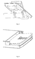
- FIG. 1 is the view of the bottom plate in the lower position, in Fig. 2 a section shown in this position.
- the FIG. 3 and FIG. 4 Illustrate the mechanism of the handle and the support in perspective views from above and below.
- Fig. 5 is shown in an exploded view of the mechanism of the handle and the support.
- Fig. 6 is the loading floor in the adjustment between the positions and in the Fig. 7 the loading floor is shown in the upper position.
- FIG. 8 schematically is the mechanism of the handle and the support according to the first embodiment of the invention, in the Fig. 9 illustrated according to the second embodiment of the invention.
- a part of the vehicle trunk is shown with a height-adjustable loading floor according to the invention in the upper position.
- the loading floor 1 is guided with its front portion in a closer unspecified link mechanism 3 and lies with its underside on the underbody 2.
- the cargo space opening of the trunk facing the loading floor section is formed in the loading floor a depression in the one Holder 4 is inserted.
- the holder 4 forms with its upper edge substantially a flat surface with the upper side of the loading floor 1 and has a mold recess 5 .
- the handle 7 is pivotally connected from the top by means of the first hinge 6 , which extends horizontally forward from the first hinge 6 .
- the handle 7 lies in the recess 5 and thus does not rise above the upper surface of the loading floor . 1
- a section of the loading floor 1 is shown in the lower position.
- an opening is formed below the holder 4 , through which the holder 4 is accessible from the underside of the loading floor 1 .
- a recess 8 is formed, in which the support 9 is located, which is pivotally connected from below to the holder 4 and to the loading floor 1 by means of the second hinge 10 .
- the support 9 extends along the entire width of the loading floor 1 and is formed at its ends in the support legs.
- the hinge 10 is formed by the bolt 11 bolted to the loading floor 1 in its edge regions , which are connected by means not shown in detail bolts formed on the support 9 eyelets 12 , and by the bolt 9 screwed to the support 9 in its center , which means Bolt not shown closer pivotally connected to the bottom of the holder 4 eyelets 14 are connected.
- the legs 15 protrude in front of the hinge 10, the legs 15 , with which the pull rods 16 are pivotally connected.
- the tie rods lead through the openings in the holder 4 upwards and are pivotally connected to the handle 7 .
- the mechanism is shown when lifting the loading floor 1 , in Fig. 6 then the entire loading floor is displayed in this position.
- the handle 7 After gripping the handle 7 by the operator, the handle 7 starts to lift and pivot about the first hinge 6 .
- the movement of the handle 7 is transmitted by means of the tie rods 16 on the legs 15 of the support 9 , which begins to fold down about the second hinge 10 from the loading floor 1 .
- the support 9 is supported with its ends from the subfloor 2 and raises the loading floor 1 upwards.
- the length of the tie rods 16 should be chosen so that after the pivoting of the handle 7 by 90 ° in the upright position, the support 9 is substantially expanded by 90 °. At this moment, the point of connection of the drawbar 16 approaches the leg 15 of the support 9 to the first hinge 6 and the support 9 is minimally unfolded during further pivoting of the handle 7, or depending on the selected conditions in the mechanism.
- the handle 7 can be folded over in the horizontal position to the rear, where it sinks into the recess 5 of the holder 4 and does not protrude beyond the upper surface of the loading floor 1 .
- the loading floor is supported in this position in the rear portion by the support 6 , which is substantially upright and is supported on the underbody 2 .
- Fig. 8 the first embodiment of the geometry of the lifting mechanism of the loading floor according to the invention in the lower position of the loading floor 1 is shown.
- the position of the mechanism in the upper position of the loading floor 1 is shown by the dotted line, the parts positions are indexed in this position with a dash.
- the length T of the drawbar 16 is the same as the distance Z of the first hinge 6 and the second hinge 10.
- the distance M from the first hinge 6 to the point of attachment of the drawbar 16 to the handle 7 corresponds to the distance P from the second hinge 10 to the point of attachment of the drawbar 16 for support 9 and while these lengths with the length T of the tie rod 16 are identical.
- the function of the spring can also by an automatic Operaumklappung the support 9 after lifting the loading floor 1 and its lowering in the front section and support of the support 9 in the inclined position on the lower floor. 2 or be replaced by the choice of a final angle position of the support 9 relative to the loading floor 1 less than 90 °.
- the second embodiment of the geometry of the loading floor lifting mechanism according to the invention is shown in the lower position of the loading floor 1 , which facilitates the folding of the support 9 from its unfolded position in the upper position of the loading floor.
- the position of the mechanism in the upper position of the loading floor 1 is shown in phantom, the parts positions are indexed in this position with a dash.
- the length M from the first hinge 6 to the point of attachment of the tie rod 16 to the handle 7 is the same as the length Z of the first hinge 6 and the second hinge 10, but the length T of the tie rod 16 and the length P of the second hinge 10 to the tie point of the tie rod 16 to support 9 are greater than the length Z are.
- the support 9 is thus formed as a slightly broken lever, whereby it forms a flat surface in the lower position of the loading floor 1 with its underside.
- the point of attachment of the drawbar 16 to the support 9 does not coincide with the first hinge 6 and the support 9 changes its position throughout the pivoting operation of the handle 7. After pivoting the handle 7 forward from its rearward horizontal position, the support begins immediately to fold in its horizontal position.
- the height-adjustable loading floor according to the invention is applicable to vehicles, especially in vehicles with a variable trunk.
Landscapes
- Engineering & Computer Science (AREA)
- Mechanical Engineering (AREA)
- Body Structure For Vehicles (AREA)
- Passenger Equipment (AREA)
Abstract
Description
- Die Erfindung betrifft einen höhenverstellbaren Ladeboden, insbesondere einen Ladeboden für den Fahrzeugkofferraum, wobei der Ladeboden von einer unteren Position in eine obere Position verstellbar ist.
- Derzeit sind verschiedene Ausführungen des durch eine zusätzliche verstellbare Bodenplatte ausgebildeten erhöhten Ladebodens im Kofferraum bekannt. Diese Bodenplatte wird mit ihrem vorderen Abschnitt z.B. in einer Kulissenführung geführt oder in einer Kurbelaufhängung gelagert, was die Abstützung dieses Abschnittes sowohl in der unteren, wie auch in der oberen Position der Platte sicherstellt. Der hintere Abschnitt der Platte liegt in der unteren Position direkt an der Auflagefläche unter dem Ladeboden, in der Regel auf dem Fahrzeugunterboden, und in der oberen Position wird er mit den Vorsprüngen abgestützt, die am Umfang des Kofferraumes, insbesondere an der Seitenverkleidung oder an der Verkleidung der Ladekante ausgebildet sind. Solche Lösungen sind zum Beispiel in den Dokumenten
EP1728684 oderDE 102007042371 beschrieben. In diesen Fällen weist die Bodenplatte im hinteren Abschnitt eine Aussparung oder einen Griff zum Ergreifen durch die Bedienperson beim Anheben und Verstellen des Ladebodens aus der unteren in die obere Position auf. Der Griff wird manchmal ausklappbar an der Oberseite des Ladebodens befestigt, damit er beim Nichtgebrauch nicht hinderlich wird, jedoch ein festes und sicheres Ergreifen durch die Bedienperson ermöglicht. - Solche Lösung hat den Nachteil, dass die Bedienperson beim Anheben des Ladebodens, insbesondere bei ausgedehnten Ladeböden mit schwerer Bodenplatte, auf den Griff mit großer Kraft senkrecht nach oben einwirken muss.
- Die Aufgabe wird durch einen erfindungsgemäßen höhenverstellbaren Ladeboden des Fahrzeugkofferraumes gelöst.
- Der Ladeboden kann zwischen unteren Position und oberen erhöhten Position verstellt werden. An der Oberseite weist der Ladeboden einen schwenkbar angebrachten Griff auf. Von der Unterseite ist zum Ladeboden ausklappbar eine Stütze befestigt, wobei der Griff mit dieser Stütze kinematisch mittels mindestens einer Zugstange verbunden ist. Beim Bewegen des Griffs wird zugleich auch die Stütze bewegt. Beim Verstellen des Ladebodens aus der unteren Position in die obere Position hebt die Bedienperson den Ladeboden an dem Griff an, wobei dieser dabei verschwenkt und seine Bewegung mittels der Zugstange an die Stütze übertragen wird, welche unter die Bodenplatte ausgeklappt wird. Die Stütze stützt sich an der Auflagefläche unter der Bodenplatte ab, in der Regel an dem Unterboden oder an einer zusätzlich ausgebildeten waagerechten Fläche, und hebt beim weiteren Ausklappen die Bodenplatte an.
- In einer vorteilhaften Ausführung nimmt der Griff in beiden Positionen des Ladebodens im Wesentlichen waagerechte Position ein, während die Stütze in der unteren Position des Ladebodens im Wesentlichen waagerechte Lage einnimmt und in der oberen Position im Wesentlichen senkrecht nach unten von der Bodenplatte herausragt. Der Griff ist so zwischen den Lagen, die der oberen und unteren Position des Ladebodens entsprechen, um 180° veschwenkt, während die Stütze im Wesentlichen um 90° verschwenkt wird. Dadurch ragt der Griff in keiner Lage in den Kofferraum hinein und ist bei seiner Nutzung nicht hinderlich. Die Stütze ragt in der unteren Position im Wesentlichen nicht unter die Bodenplatte heraus, die so im Wesentlichen mit ihrer unteren Fläche auf der Auflagefläche darunter liegt. In der oberen Position der Bodenplatte stützt die Stütze jedoch den hinteren Bodenplattenabschnitt ab, sodass er nicht extra zusätzlich unterstützt werden muss.
- Die Bodenplatte weist vorteilhaft an der Oberseite eine Aussparung für den Griff auf, wobei der Griff in beiden Ladebodenpositionen in oder unter der Ebene der
- Oberseite liegt. Die Aussparung ist so ausgebildet, damit die Bedienperson den Griff in beiden Endlagen einfach greifen kann, z.B. wird er lokal mehr eingesenkt.
- Die Bodenplatte kann auch an der Unterseite eine Aussparung für die Stütze aufweisen, wobei diese Stütze in der unteren Position der Bodenplatte in oder über der Ebene der Unterseite der Bodenplatte liegt. Die Bodenplatte kann dadurch mit ihrer gesamten Unterseite oder wenigstens mit deren Randbereichen direkt an der Auflagefläche bzw. dem Unterboden liegen.
- Der Griff ist vorteilhaft als ein einseitiger Hebel ausgeführt, dessen ein Ende zur Bodenplatte befestigt und das andere Ende für das Ergreifen durch die Bedienperson angepasst ist. Die Stütze hat dann die Gestalt eines zweiseitigen Hebels, wobei zum ersten Schenkel eine Zugstange angeschlossen ist und der zweite Schenkel für den Kontakt mit der Auflagefläche angepasst ist, an der die Bodenplatte in ihrer unteren Position abgestützt wird. Dank dessen wird beim Verschwenken des Griffes um 180° die Stütze um 90° ausgeklappt.
- In einer vorteilhaften Ausführung ist der Griff mit einem ersten Scharnier und die Stütze mit einem zweiten Scharnier zur Bodenplatte befestigt, wobei beide Scharniere horizontale quergelagerte Drehachsen haben und die Achse des erstens Scharniers über der Achse des zweiten Scharniers liegt. Dadurch kann eine ideale Kinematik des gesamten Mechanismus erzielt werden.
- Die Länge der Zugstange ist vorteilhaft im Wesentlichen gleich wie die Distanz des ersten und zweiten Scharniers, und dabei ist die Entfernung vom ersten Scharnier zur Anbindungsstelle des Zugstange zum Griff und die Entfernung vom zweiten Scharnier zur Anbindungsstelle der Zugstange zur Stütze im Wesentlichen gleich und mit der Länge der Zugstange identisch. In der unteren Position des Ladebodens bilden die Drehpunkte des Mechanismus im Wesentlichen ein Quadrat, während sie in der oberen Position des Ladebodens die Form L bilden.
- Um das Umklappen der Stütze aus der im Wesentlichen aufrechter Stellung in der oberen Position des Ladebodens zu vereinfachen kann die Entfernung vom ersten Scharnier zur Anbindungsstelle der Zugstange zum Griff im Wesentlichen gleich wie die Entfernung des erstens und zweitens Scharniers und die Länge der Zugstange sowie die Entfernung vom zweiten Scharnier zur Anbindungsstelle der Zugstange zur Stütze dabei größer als die Entfernung des erstens und zweitens Scharniers sein. Dank der Längendifferenz liegt die Anbindungsstelle der Zugstange zur Stütze in der oberen Position des Ladebodens außerhalb der Achse des erstens Scharniers sodass die Stütze beim Anheben des Griffes sofort bewegt wird.
- Der Griff oder die Stütze können eine Rückfeder für die Rücksetzung in die der unteren Position des Ladebodens entsprechende Lage, also für das Einklappen der Stütze in die Ebene des Ladebodens, aufweisen. Dadurch wird insbesondere das Einklappen der Stütze beim Verstellen des Ladebodens aus der oberen in die untere Position vereinfacht.
- In der
Fig. 1 ist die Ansicht der Bodenplatte in der unteren Position, inFig. 2 ein Schnitt in dieser Position dargestellt. DieFig. 3 und Fig. 4 stellen den Mechanismus des Griffes und der Stütze in perspektivischen Ansichten von oben und unten dar. In derFig. 5 ist in einer Explosionszeichnung der Mechanismus des Griffes und der Stütze dargestellt. In derFig. 6 ist der Ladeboden bei der Verstellung zwischen den Positionen und in derFig. 7 der Ladeboden in der oberen Position dargestellt. - In der
Fig. 8 ist schematisch der Mechanismus des Griffes und der Stütze nach dem ersten erfindungsgemäßen Ausführungsbeispiel, in derFig. 9 nach dem zweiten erfindungsgemäßen Ausführungsbeispiel dargestellt. - In der
Fig. 1 ist ein Teil des Fahrzeugkofferraumes mit einem erfindungsgemäßen höhenverstellbaren Ladeboden in der oberen Position dargestellt. Der Ladeboden 1 ist mit seinem vorderen Abschnitt in einem näher nicht spezifizierten Kulissenmechanismus 3 geführt und liegt mit seiner Unterseite auf dem Unterboden 2. Im hinteren, der Laderaumöffnung des Kofferraumes zugewandten Ladebodenabschnitt ist in dem Ladeboden eine Einsenkung ausgebildet, in der ein Halter 4 eingesetzt ist. Der Halter 4 bildet mit seinem oberen Rand im Wesentlichen eine ebene Fläche mit der Oberseite des Ladebodens 1 und weist eine Formaussparung 5 auf. Zum Halter 4 ist von der Oberseite mittels des erstens Scharniers 6 schwenkbar der Griff 7 angeschlossen, der sich horizontal nach vorne vom ersten Scharnier 6 erstreckt. Der Griff 7 liegt in der Aussparung 5 und erhebt sich somit nicht über die obere Fläche des Ladebodens 1. - In der
Fig. 2 ist ein Schnitt des Ladebodens 1 in der unteren Position dargestellt. Im Ladeboden 1 ist unter dem Halter 4 eine Öffnung ausgebildet, durch die der Halter 4 von der Unterseite des Ladebodens 1 zugänglich ist. An der Unterseite des Ladebodens 1 ist eine Aussparung 8 ausgebildet, in der sich die Stütze 9 befindet, die schwenkbar von unten mit dem Halter 4 und mit dem Ladeboden 1 mittels des zweiten Scharniers 10 verbunden ist. Aus derFig. 3 ist die Ausführung des Hebemechanismus ersichtlich. Die Stütze 9 erstreckt sich entlang der ganzen Breite des Ladebodens 1 und ist an ihren Enden in die Stützbeine ausgeformt. Der Scharnier 10 wird gebildet durch die zum Ladeboden 1 in seinen Randbereichen angeschraubten Angel 11, die mittels näher nicht abgebildeten Bolzen mit den an der Stütze 9 ausgebildeten Ösen 12 verbunden sind, und durch die zur Stütze 9 in ihrer Mitte angeschraubten Angel 13, die mittels näher nicht abgebildeten Bolzen schwenkbar mit den von unten am Halter 4 ausgebildeten Ösen 14 verbunden sind. Von der Stütze 9 ragen vor das Scharnier 10 die Schenkel 15 heraus, mit denen schwenkbar die Zugstangen 16 verbunden sind. Die Zugstangen führen durch die Öffnungen im Halter 4 nach oben hin und sind schwenkbar mit dem Griff 7 verbunden. - In der
Fig. 4 undFig. 5 ist der Mechanismus beim Anheben des Ladebodens 1 dargestellt, inFig. 6 ist dann der gesamte Ladeboden in dieser Position angezeigt. Nach dem Ergreifen des Griffes 7 durch die Bedienperson beginnt der Griff 7 sich anzuheben und um das erste Scharnier 6 zu verschwenken. Die Bewegung des Griffes 7 wird mittels der Zugstangen 16 auf die Schenkel 15 der Stütze 9 übertragen, die sich um das zweite Scharnier 10 nach unten vom Ladeboden 1 auszuklappen beginnt. Die Stütze 9 stützt sich mit ihren Enden vom Unterboden 2 ab und hebt den Ladeboden 1 nach oben an. - Die Länge der Zugstangen 16 soll so gewählt werden, damit nach dem Verschwenken des Griffes 7 um 90° in die aufrechte Position die Stütze 9 im Wesentlichen um 90° ausgeklappt wird. In diesem Moment nähert sich der Punkt der Verbindung der Zugstange 16 am Schenkel 15 der Stütze 9 zum ersten Scharnier 6 und die Stütze 9 wird beim weiteren Verschwenken des Griffes 7 nur minimal, bzw. abhängig von der gewählten Verhältnissen im Mechanismus gar nicht weiter ausgeklappt. Der Griff 7 kann so in die waagerechte Lage nach hinten umgeklappt werden, wo er in die Aussparung 5 des Halters 4 einsinkt und über die obere Fläche des Ladebodens 1 nicht herausragt. Der Ladeboden ist in dieser Position im hinteren Abschnitt durch die Stütze 6 abgestützt, die im Wesentlichen aufrecht steht und sich an dem Unterboden 2 abstützt.
- In der
Fig. 8 ist das erste Ausführungsbeispiel der Geometrie des erfindungsgemäßen Hebemechanismus des Ladebodens in der unteren Position des Ladebodens 1 dargestellt. Die Lage des Mechanismus in der oberen Position des Ladebodens 1 ist mit der strichpunktierten Linie dargestellt, wobei die Teilepositionen in dieser Position mit einem Strich indexiert sind. Die Länge T der Zugstange 16 ist gleich wie die Entfernung Z des ersten Scharniers 6 und des zweitens Scharniers 10. Die Distanz M vom ersten Scharnier 6 zur Anbindungsstelle der Zugstange 16 zum Griff 7 entspricht der Entfernung P vom zweiten Scharnier 10 zur Anbindungsstelle der Zugstange 16 zur Stütze 9 und dabei sind diese Längen mit der Länge T der Zugstange 16 identisch. Nach dem Verschwenken das Griffes 7 um 90° nach hinten koinzidiert die Anbindungsstelle der Zugstange 16 zur Stütze 9 mit dem ersten Scharnier 6 und weiteres Verschwenken des Griffes 7 nach hinten wird die Position der Stütze 9 weiter nicht verändern, da sich die Zugstange 16 um die gleiche Achse wie der Griff 7 verschwenkt. Um den Ladeboden 1 in die untere Position zurückzusetzen, verschwenkt die Bedienperson den Griff 7 nach vorne, wird jedoch die Stütze 9 nicht verschwenkt, hat das Verschwenken des Griffes 7 kein Einfluss auf ihre Position. Deshalb ist günstig die Stütze 9 mit einer nicht dargestellten Rückfeder zu versehen, die sie in die Position zurücksetzt, welche der unteren Position des Ladebodens 1 entspricht, also die Stütze 9 in die Ebene des Ladebodens 1 umklappt. Die Funktion der Feder kann auch durch eine selbsttätige Teilumklappung der Stütze 9 nach dem Anheben des Ladebodens 1 und dessen Absenkung im vorderen Abschnitt und Abstützung der Stütze 9 in der Schräglage am Unterboden 2 oder auch durch die Wahl einer Endwinkellage der Stütze 9 gegenüber dem Ladeboden 1 kleiner als 90° ersetzt werden. - In der
Fig. 9 ist das zweite Ausführungsbeispiel der Geometrie des erfindungsgemäßen Hebemechanismus des Ladebodens in der unteren Position des Ladebodens 1 dargestellt, das das Einklappen der Stütze 9 aus ihrer ausgeklappten Position bei oberer Position des Ladebodens erleichtert. Die Lage des Mechanismus bei der oberen Position des Ladebodens 1 ist strichpunktiert dargestellt, wobei die Teilepositionen in dieser Position mit einem Strich indexiert sind. Die Länge M vom ersten Scharnier 6 zur Anbindungsstelle der Zugstange 16 zum Griff 7 ist gleich wie die Länge Z des ersten Scharniers 6 und des zweiten Scharniers 10, jedoch die Länge T der Zugstange 16 und die Länge P vom zweiten Scharnier 10 zur Anbindungsstelle der Zugstange 16 zur Stütze 9 größer als die Länge Z sind. Die Stütze 9 ist also als leicht gebrochener Hebel ausgebildet, wodurch sie in der unteren Position des Ladebodens 1 mit seiner Unterseite ebene Fläche bildet. Infolge solcher Geometrie koinzidiert die Anbindungsstelle der Zugstange 16 zur Stütze 9 nicht mit dem ersten Scharnier 6 und die Stütze 9 ändert ihre Position während des ganzen Verschwenkvorganges des Griffes 7. Nach dem Verschwenken des Griffes 7 vorwärts aus seiner hinteren waagerechten Position beginnt die Stütze sich sofort in ihre waagerechte Position umzuklappen. - Im gesamten Dokument werden die Richtungen und Positionen entsprechend den üblich genutzten Richtungen und Positionen der Teile im Fahrzeug angeführt.
- Der erfindungsgemäße höhenverstellbare Ladeboden ist bei Fahrzeugen, insbesondere bei Fahrzeugen mit variablem Kofferraum anwendbar.
Claims (8)
- Höhenverstellbarer Ladeboden, insbesondere ein Ladeboden für den Fahrzeugkofferraum, der zwischen einer unteren Position und einer oberen Position verstellbar ist und an der Oberseite des Ladebodens (1) einen schwenkbar angebrachten Griff (7) aufweist, dadurch gekennzeichnet, dass der Ladeboden (1) an der Unterseite eine ausklappbar befestigte Stütze (9) aufweist, wobei der Griff (7) mit der Stütze kinematisch mittels mindestens einer Zugstange (16) verbunden ist.
- Höhenverstellbarer Ladeboden nach Anspruch 1 dadurch gekennzeichnet, dass sich der Griff (7) in der unteren sowie oberen Position des Ladebodens (1) im Wesentlichen waagerecht erstreckt, wobei die Stütze (9) in der unteren Position des Ladebodens (1) im Wesentlichen waagerechte Lage einnimmt und in der oberen Position des Ladebodens (1) im Wesentlichen senkrecht nach unten vom Ladeboden (1) herausragt.
- Höhenverstellbarer Ladeboden nach einem der vorgenannten Ansprüche dadurch gekennzeichnet, dass der Ladeboden (1) an der Oberseite eine Aussparung (5) für den Griff (7) aufweist und dass der Griff (7) in beiden Positionen des Ladebodens (1) in oder unter der Ebene seiner Oberseite liegt.
- Höhenverstellbarer Ladeboden nach einem der vorgenannten Ansprüche dadurch gekennzeichnet, dass der Ladeboden (1) an der Unterseite eine Aussparung (8) für die Stütze (9) aufweist und dass die Stütze (9) in der unteren Position des Ladebodens (1) in oder über der Ebene seiner Unterseite liegt.
- Höhenverstellbarer Ladeboden nach einem der vorgenannten Ansprüche dadurch gekennzeichnet, dass der Griff (7) als ein einseitiger Hebel ausgeführt ist, dessen ein Ende zum Ladeboden (1) befestigt ist und das andere Ende für das Ergreifen durch die Bedienperson angepasst ist, und dass die Stütze (9) die Gestalt eines zweiseitigen Hebels hat, wobei zu seinem ersten Schenkel eine Zugstange (16) angeschlossen ist und der zweite Schenkel für den Kontakt mit der Auflagefläche (2) angepasst ist, an der sich der Ladeboden (1) in seiner unteren Position abstützt.
- Höhenverstellbarer Ladeboden nach einem der vorgenannten Ansprüche dadurch gekennzeichnet, dass der Griff (7) am Ladeboden (1) mittels eines erstens Scharniers (6) und dass die Stütze (9) am Ladeboden (1) mittels des zweitens Scharniers (10) befestigt ist, wobei beide Scharniere (6,10) horizontale quergelagerte Drehachsen haben und wobei die die Achse des erstens Scharniers (6) über der Achse des zweiten Scharniers (10) liegt.
- Höhenverstellbarer Ladeboden nach einem der Ansprüche 1 bis 6 dadurch gekennzeichnet, dass die Länge (T) der Zugstange (16) vorteilhaft im Wesentlichen gleich wie die Distanz (Z) des ersten Scharniers (6) und des zweiten Scharniers (10), und dabei ist die Entfernung (M) vom ersten Scharnier (6) zur Anbindungsstelle der Zugstange (16) zum Griff (7) und die Entfernung (P) vom zweiten Scharnier (10) zur Anbindungsstelle der Zugstange (16) zur Stütze (9) im Wesentlichen gleich und mit der Länge (T) der Zugstange (16) identisch.
- Höhenverstellbarer Ladeboden nach einem der Ansprüche 1 bis 6 dadurch gekennzeichnet, dass die Entfernung (M) vom ersten Scharnier (6) zur Anbindungsstelle der Zugstange (16) zum Griff (7) im Wesentlichen gleich wie die Entfernung (Z) des erstens Scharniers (6) und des zweiten Scharniers (10) ist und dass die Länge (T) der Zugstange (16) und die Entfernung (P) vom zweiten Scharnier (10) zur Anbindungsstelle der Zugstange (16) zur Stütze (9) größer als die Entfernung (Z) des ersten Scharniers (6) und des zweiten Scharniers (10) ist.
Applications Claiming Priority (1)
| Application Number | Priority Date | Filing Date | Title |
|---|---|---|---|
| CZ20100768A CZ2010768A3 (cs) | 2010-10-21 | 2010-10-21 | Výškove prestavitelná podlaha |
Publications (2)
| Publication Number | Publication Date |
|---|---|
| EP2444285A1 true EP2444285A1 (de) | 2012-04-25 |
| EP2444285B1 EP2444285B1 (de) | 2013-08-28 |
Family
ID=44905812
Family Applications (1)
| Application Number | Title | Priority Date | Filing Date |
|---|---|---|---|
| EP11466031.9A Active EP2444285B1 (de) | 2010-10-21 | 2011-10-17 | Höhenverstellbarer Ladeboden |
Country Status (2)
| Country | Link |
|---|---|
| EP (1) | EP2444285B1 (de) |
| CZ (1) | CZ2010768A3 (de) |
Cited By (1)
| Publication number | Priority date | Publication date | Assignee | Title |
|---|---|---|---|---|
| US9415725B2 (en) | 2013-12-02 | 2016-08-16 | GM Global Technology Operations LLC | Load compartment arrangement for a vehicle and vehicle with the load compartment arrangement |
Families Citing this family (1)
| Publication number | Priority date | Publication date | Assignee | Title |
|---|---|---|---|---|
| US12128806B2 (en) | 2022-03-02 | 2024-10-29 | GM Global Technology Operations LLC | Support device for a moveable load bearing vehicle component |
Citations (5)
| Publication number | Priority date | Publication date | Assignee | Title |
|---|---|---|---|---|
| JP2002370677A (ja) * | 2001-06-14 | 2002-12-24 | Mitsuiya Kogyo Kk | 自動車の荷台部構造 |
| EP1728684A1 (de) | 2005-05-31 | 2006-12-06 | Peugeot Citroën Automobiles S.A. | Hebevorrichtung für einen Kraftfahrzeug Kofferraum |
| JP2008037299A (ja) * | 2006-08-08 | 2008-02-21 | Mazda Motor Corp | 車両の後部荷室構造 |
| DE102007042371A1 (de) | 2007-09-06 | 2009-03-12 | GM Global Technology Operations, Inc., Detroit | Höhenverstellvorrichtung für den Ladeboden eines Kraftfahrzeugs |
| US20100090502A1 (en) * | 2008-10-09 | 2010-04-15 | Gm Global Technology Operations, Inc. | Adjustable Rear Load Floor for a Hybrid Vehicle |
-
2010
- 2010-10-21 CZ CZ20100768A patent/CZ2010768A3/cs unknown
-
2011
- 2011-10-17 EP EP11466031.9A patent/EP2444285B1/de active Active
Patent Citations (5)
| Publication number | Priority date | Publication date | Assignee | Title |
|---|---|---|---|---|
| JP2002370677A (ja) * | 2001-06-14 | 2002-12-24 | Mitsuiya Kogyo Kk | 自動車の荷台部構造 |
| EP1728684A1 (de) | 2005-05-31 | 2006-12-06 | Peugeot Citroën Automobiles S.A. | Hebevorrichtung für einen Kraftfahrzeug Kofferraum |
| JP2008037299A (ja) * | 2006-08-08 | 2008-02-21 | Mazda Motor Corp | 車両の後部荷室構造 |
| DE102007042371A1 (de) | 2007-09-06 | 2009-03-12 | GM Global Technology Operations, Inc., Detroit | Höhenverstellvorrichtung für den Ladeboden eines Kraftfahrzeugs |
| US20100090502A1 (en) * | 2008-10-09 | 2010-04-15 | Gm Global Technology Operations, Inc. | Adjustable Rear Load Floor for a Hybrid Vehicle |
Cited By (1)
| Publication number | Priority date | Publication date | Assignee | Title |
|---|---|---|---|---|
| US9415725B2 (en) | 2013-12-02 | 2016-08-16 | GM Global Technology Operations LLC | Load compartment arrangement for a vehicle and vehicle with the load compartment arrangement |
Also Published As
| Publication number | Publication date |
|---|---|
| EP2444285B1 (de) | 2013-08-28 |
| CZ2010768A3 (cs) | 2012-05-02 |
Similar Documents
| Publication | Publication Date | Title |
|---|---|---|
| DE102019122544B4 (de) | Konsoleneinrichtung für Nutzfahrzeugkabine | |
| EP2183127A1 (de) | Fahrzeugsitz für ein kraftfahrzeug | |
| EP2899070A1 (de) | Vorrichtung zur Höhenverstellung eines Ladebodens in einem Fahrzeug | |
| WO2012017049A1 (de) | Befestigungsvorrichtung für einen fahrzeugsitz und fahrzeugsitz | |
| EP1801008A2 (de) | Verriegelungseinrichtung für ein Tischsystem bei einem Sitz, insbesondere Fluggastsitz | |
| EP1718494A1 (de) | Fahrzeugsitz, insbesondere für ein kraftfahrzeug, mit einer klappbaren lehne und einerklappbaren sitzbasis und verfahren | |
| DE102011108493B4 (de) | Dachträgeranordnung mit Verlagerung eines schwenkbaren Dachträgerquerholms | |
| DE102018100560B4 (de) | Rampe und Fahrzeugrampenvorrichtung | |
| DE102014202569B4 (de) | Fahrzeugsitz | |
| EP2444285B1 (de) | Höhenverstellbarer Ladeboden | |
| DE9112213U1 (de) | Notsitz, insbesondere für Führerkabinen von Nutzfahrzeugen | |
| EP3159452B1 (de) | Frontlader | |
| DE2001842A1 (de) | Sitz,insbesondere fuer Kraftfahrzeuge | |
| DE102010003932A1 (de) | Verdeckvorrichtung für einen Lastentransportbehälter | |
| DE102005015237A1 (de) | Passagiersitz, insbeondere Fahr- oder Fluggastsitz | |
| DE3814628C2 (de) | ||
| EP1847447B1 (de) | Runge für die Ladeöffnung eines Fahrzeugaufbaus | |
| DE102008063138A1 (de) | Klapptisch für ein Nutzfahrzeug | |
| DE102005017772B4 (de) | Kraftfahrzeug mit einem schwenkbaren Sitz | |
| DE102015013322B3 (de) | Ladeboden für einen Gepäckraum eines Fahrzeuges | |
| DE10344978B4 (de) | Vorrichtung zur erleichterten Entriegelung eines Kraftfahrzeugsitzes | |
| DE102014205731B4 (de) | Fahrzeugsitz | |
| EP2700540A1 (de) | Laderaumerweiterung | |
| EP1431106B1 (de) | Klappbarer Sitz | |
| EP2978636B1 (de) | Behältnis, insbesondere zum einbauen in eine heckklappe eines kraftfahrzeugs |
Legal Events
| Date | Code | Title | Description |
|---|---|---|---|
| AK | Designated contracting states |
Kind code of ref document: A1 Designated state(s): AL AT BE BG CH CY CZ DE DK EE ES FI FR GB GR HR HU IE IS IT LI LT LU LV MC MK MT NL NO PL PT RO RS SE SI SK SM TR |
|
| AX | Request for extension of the european patent |
Extension state: BA ME |
|
| PUAI | Public reference made under article 153(3) epc to a published international application that has entered the european phase |
Free format text: ORIGINAL CODE: 0009012 |
|
| 17P | Request for examination filed |
Effective date: 20121025 |
|
| GRAP | Despatch of communication of intention to grant a patent |
Free format text: ORIGINAL CODE: EPIDOSNIGR1 |
|
| INTG | Intention to grant announced |
Effective date: 20130507 |
|
| GRAS | Grant fee paid |
Free format text: ORIGINAL CODE: EPIDOSNIGR3 |
|
| GRAA | (expected) grant |
Free format text: ORIGINAL CODE: 0009210 |
|
| AK | Designated contracting states |
Kind code of ref document: B1 Designated state(s): AL AT BE BG CH CY CZ DE DK EE ES FI FR GB GR HR HU IE IS IT LI LT LU LV MC MK MT NL NO PL PT RO RS SE SI SK SM TR |
|
| REG | Reference to a national code |
Ref country code: GB Ref legal event code: FG4D Free format text: NOT ENGLISH |
|
| REG | Reference to a national code |
Ref country code: CH Ref legal event code: EP |
|
| REG | Reference to a national code |
Ref country code: AT Ref legal event code: REF Ref document number: 629133 Country of ref document: AT Kind code of ref document: T Effective date: 20130915 |
|
| REG | Reference to a national code |
Ref country code: IE Ref legal event code: FG4D Free format text: LANGUAGE OF EP DOCUMENT: GERMAN |
|
| REG | Reference to a national code |
Ref country code: DE Ref legal event code: R096 Ref document number: 502011001261 Country of ref document: DE Effective date: 20131024 |
|
| REG | Reference to a national code |
Ref country code: LT Ref legal event code: MG4D |
|
| REG | Reference to a national code |
Ref country code: NL Ref legal event code: VDEP Effective date: 20130828 |
|
| PG25 | Lapsed in a contracting state [announced via postgrant information from national office to epo] |
Ref country code: CY Free format text: LAPSE BECAUSE OF FAILURE TO SUBMIT A TRANSLATION OF THE DESCRIPTION OR TO PAY THE FEE WITHIN THE PRESCRIBED TIME-LIMIT Effective date: 20130821 Ref country code: IS Free format text: LAPSE BECAUSE OF FAILURE TO SUBMIT A TRANSLATION OF THE DESCRIPTION OR TO PAY THE FEE WITHIN THE PRESCRIBED TIME-LIMIT Effective date: 20131228 Ref country code: SE Free format text: LAPSE BECAUSE OF FAILURE TO SUBMIT A TRANSLATION OF THE DESCRIPTION OR TO PAY THE FEE WITHIN THE PRESCRIBED TIME-LIMIT Effective date: 20130828 Ref country code: PT Free format text: LAPSE BECAUSE OF FAILURE TO SUBMIT A TRANSLATION OF THE DESCRIPTION OR TO PAY THE FEE WITHIN THE PRESCRIBED TIME-LIMIT Effective date: 20131230 Ref country code: LT Free format text: LAPSE BECAUSE OF FAILURE TO SUBMIT A TRANSLATION OF THE DESCRIPTION OR TO PAY THE FEE WITHIN THE PRESCRIBED TIME-LIMIT Effective date: 20130828 Ref country code: HR Free format text: LAPSE BECAUSE OF FAILURE TO SUBMIT A TRANSLATION OF THE DESCRIPTION OR TO PAY THE FEE WITHIN THE PRESCRIBED TIME-LIMIT Effective date: 20130828 Ref country code: NO Free format text: LAPSE BECAUSE OF FAILURE TO SUBMIT A TRANSLATION OF THE DESCRIPTION OR TO PAY THE FEE WITHIN THE PRESCRIBED TIME-LIMIT Effective date: 20131128 |
|
| REG | Reference to a national code |
Ref country code: NL Ref legal event code: VDEP Effective date: 20130828 |
|
| PG25 | Lapsed in a contracting state [announced via postgrant information from national office to epo] |
Ref country code: SI Free format text: LAPSE BECAUSE OF FAILURE TO SUBMIT A TRANSLATION OF THE DESCRIPTION OR TO PAY THE FEE WITHIN THE PRESCRIBED TIME-LIMIT Effective date: 20130828 Ref country code: GR Free format text: LAPSE BECAUSE OF FAILURE TO SUBMIT A TRANSLATION OF THE DESCRIPTION OR TO PAY THE FEE WITHIN THE PRESCRIBED TIME-LIMIT Effective date: 20131129 Ref country code: PL Free format text: LAPSE BECAUSE OF FAILURE TO SUBMIT A TRANSLATION OF THE DESCRIPTION OR TO PAY THE FEE WITHIN THE PRESCRIBED TIME-LIMIT Effective date: 20130828 Ref country code: FI Free format text: LAPSE BECAUSE OF FAILURE TO SUBMIT A TRANSLATION OF THE DESCRIPTION OR TO PAY THE FEE WITHIN THE PRESCRIBED TIME-LIMIT Effective date: 20130828 Ref country code: LV Free format text: LAPSE BECAUSE OF FAILURE TO SUBMIT A TRANSLATION OF THE DESCRIPTION OR TO PAY THE FEE WITHIN THE PRESCRIBED TIME-LIMIT Effective date: 20130828 |
|
| PG25 | Lapsed in a contracting state [announced via postgrant information from national office to epo] |
Ref country code: CY Free format text: LAPSE BECAUSE OF FAILURE TO SUBMIT A TRANSLATION OF THE DESCRIPTION OR TO PAY THE FEE WITHIN THE PRESCRIBED TIME-LIMIT Effective date: 20130828 |
|
| BERE | Be: lapsed |
Owner name: SKODA AUTO A.S. Effective date: 20131031 |
|
| PG25 | Lapsed in a contracting state [announced via postgrant information from national office to epo] |
Ref country code: DK Free format text: LAPSE BECAUSE OF FAILURE TO SUBMIT A TRANSLATION OF THE DESCRIPTION OR TO PAY THE FEE WITHIN THE PRESCRIBED TIME-LIMIT Effective date: 20130828 Ref country code: RO Free format text: LAPSE BECAUSE OF FAILURE TO SUBMIT A TRANSLATION OF THE DESCRIPTION OR TO PAY THE FEE WITHIN THE PRESCRIBED TIME-LIMIT Effective date: 20130828 Ref country code: EE Free format text: LAPSE BECAUSE OF FAILURE TO SUBMIT A TRANSLATION OF THE DESCRIPTION OR TO PAY THE FEE WITHIN THE PRESCRIBED TIME-LIMIT Effective date: 20130828 Ref country code: NL Free format text: LAPSE BECAUSE OF FAILURE TO SUBMIT A TRANSLATION OF THE DESCRIPTION OR TO PAY THE FEE WITHIN THE PRESCRIBED TIME-LIMIT Effective date: 20130828 Ref country code: SK Free format text: LAPSE BECAUSE OF FAILURE TO SUBMIT A TRANSLATION OF THE DESCRIPTION OR TO PAY THE FEE WITHIN THE PRESCRIBED TIME-LIMIT Effective date: 20130828 |
|
| PG25 | Lapsed in a contracting state [announced via postgrant information from national office to epo] |
Ref country code: ES Free format text: LAPSE BECAUSE OF FAILURE TO SUBMIT A TRANSLATION OF THE DESCRIPTION OR TO PAY THE FEE WITHIN THE PRESCRIBED TIME-LIMIT Effective date: 20130828 Ref country code: IT Free format text: LAPSE BECAUSE OF FAILURE TO SUBMIT A TRANSLATION OF THE DESCRIPTION OR TO PAY THE FEE WITHIN THE PRESCRIBED TIME-LIMIT Effective date: 20130828 Ref country code: MC Free format text: LAPSE BECAUSE OF FAILURE TO SUBMIT A TRANSLATION OF THE DESCRIPTION OR TO PAY THE FEE WITHIN THE PRESCRIBED TIME-LIMIT Effective date: 20130828 |
|
| REG | Reference to a national code |
Ref country code: DE Ref legal event code: R097 Ref document number: 502011001261 Country of ref document: DE |
|
| PLBE | No opposition filed within time limit |
Free format text: ORIGINAL CODE: 0009261 |
|
| STAA | Information on the status of an ep patent application or granted ep patent |
Free format text: STATUS: NO OPPOSITION FILED WITHIN TIME LIMIT |
|
| REG | Reference to a national code |
Ref country code: IE Ref legal event code: MM4A |
|
| 26N | No opposition filed |
Effective date: 20140530 |
|
| PG25 | Lapsed in a contracting state [announced via postgrant information from national office to epo] |
Ref country code: CZ Free format text: LAPSE BECAUSE OF NON-PAYMENT OF DUE FEES Effective date: 20131017 |
|
| REG | Reference to a national code |
Ref country code: DE Ref legal event code: R097 Ref document number: 502011001261 Country of ref document: DE Effective date: 20140530 |
|
| PG25 | Lapsed in a contracting state [announced via postgrant information from national office to epo] |
Ref country code: BE Free format text: LAPSE BECAUSE OF NON-PAYMENT OF DUE FEES Effective date: 20131031 |
|
| PG25 | Lapsed in a contracting state [announced via postgrant information from national office to epo] |
Ref country code: IE Free format text: LAPSE BECAUSE OF NON-PAYMENT OF DUE FEES Effective date: 20131017 |
|
| PG25 | Lapsed in a contracting state [announced via postgrant information from national office to epo] |
Ref country code: SM Free format text: LAPSE BECAUSE OF FAILURE TO SUBMIT A TRANSLATION OF THE DESCRIPTION OR TO PAY THE FEE WITHIN THE PRESCRIBED TIME-LIMIT Effective date: 20130828 |
|
| REG | Reference to a national code |
Ref country code: CH Ref legal event code: PL |
|
| PG25 | Lapsed in a contracting state [announced via postgrant information from national office to epo] |
Ref country code: TR Free format text: LAPSE BECAUSE OF FAILURE TO SUBMIT A TRANSLATION OF THE DESCRIPTION OR TO PAY THE FEE WITHIN THE PRESCRIBED TIME-LIMIT Effective date: 20130828 |
|
| PG25 | Lapsed in a contracting state [announced via postgrant information from national office to epo] |
Ref country code: RS Free format text: LAPSE BECAUSE OF FAILURE TO SUBMIT A TRANSLATION OF THE DESCRIPTION OR TO PAY THE FEE WITHIN THE PRESCRIBED TIME-LIMIT Effective date: 20131128 Ref country code: HU Free format text: LAPSE BECAUSE OF FAILURE TO SUBMIT A TRANSLATION OF THE DESCRIPTION OR TO PAY THE FEE WITHIN THE PRESCRIBED TIME-LIMIT; INVALID AB INITIO Effective date: 20111017 Ref country code: LI Free format text: LAPSE BECAUSE OF NON-PAYMENT OF DUE FEES Effective date: 20141031 Ref country code: MK Free format text: LAPSE BECAUSE OF FAILURE TO SUBMIT A TRANSLATION OF THE DESCRIPTION OR TO PAY THE FEE WITHIN THE PRESCRIBED TIME-LIMIT Effective date: 20130828 Ref country code: LU Free format text: LAPSE BECAUSE OF NON-PAYMENT OF DUE FEES Effective date: 20131017 Ref country code: BG Free format text: LAPSE BECAUSE OF FAILURE TO SUBMIT A TRANSLATION OF THE DESCRIPTION OR TO PAY THE FEE WITHIN THE PRESCRIBED TIME-LIMIT Effective date: 20130828 Ref country code: CH Free format text: LAPSE BECAUSE OF NON-PAYMENT OF DUE FEES Effective date: 20141031 |
|
| PG25 | Lapsed in a contracting state [announced via postgrant information from national office to epo] |
Ref country code: MT Free format text: LAPSE BECAUSE OF FAILURE TO SUBMIT A TRANSLATION OF THE DESCRIPTION OR TO PAY THE FEE WITHIN THE PRESCRIBED TIME-LIMIT Effective date: 20130828 |
|
| REG | Reference to a national code |
Ref country code: FR Ref legal event code: PLFP Year of fee payment: 5 |
|
| REG | Reference to a national code |
Ref country code: FR Ref legal event code: PLFP Year of fee payment: 6 |
|
| REG | Reference to a national code |
Ref country code: FR Ref legal event code: PLFP Year of fee payment: 7 |
|
| REG | Reference to a national code |
Ref country code: AT Ref legal event code: MM01 Ref document number: 629133 Country of ref document: AT Kind code of ref document: T Effective date: 20161017 |
|
| PG25 | Lapsed in a contracting state [announced via postgrant information from national office to epo] |
Ref country code: AT Free format text: LAPSE BECAUSE OF NON-PAYMENT OF DUE FEES Effective date: 20161017 |
|
| REG | Reference to a national code |
Ref country code: FR Ref legal event code: PLFP Year of fee payment: 8 |
|
| PG25 | Lapsed in a contracting state [announced via postgrant information from national office to epo] |
Ref country code: AL Free format text: LAPSE BECAUSE OF FAILURE TO SUBMIT A TRANSLATION OF THE DESCRIPTION OR TO PAY THE FEE WITHIN THE PRESCRIBED TIME-LIMIT Effective date: 20130828 |
|
| P01 | Opt-out of the competence of the unified patent court (upc) registered |
Effective date: 20230626 |
|
| PGFP | Annual fee paid to national office [announced via postgrant information from national office to epo] |
Ref country code: FR Payment date: 20250630 Year of fee payment: 15 |
|
| PGFP | Annual fee paid to national office [announced via postgrant information from national office to epo] |
Ref country code: GB Payment date: 20250804 Year of fee payment: 15 |
|
| PGFP | Annual fee paid to national office [announced via postgrant information from national office to epo] |
Ref country code: DE Payment date: 20250630 Year of fee payment: 15 |