EP2440428B1 - Kraftfahrzeug mit einem u-förmigen bügel - Google Patents
Kraftfahrzeug mit einem u-förmigen bügel Download PDFInfo
- Publication number
- EP2440428B1 EP2440428B1 EP10722712A EP10722712A EP2440428B1 EP 2440428 B1 EP2440428 B1 EP 2440428B1 EP 10722712 A EP10722712 A EP 10722712A EP 10722712 A EP10722712 A EP 10722712A EP 2440428 B1 EP2440428 B1 EP 2440428B1
- Authority
- EP
- European Patent Office
- Prior art keywords
- shaped member
- shaped bracket
- motor vehicle
- rivet
- vehicle according
- Prior art date
- Legal status (The legal status is an assumption and is not a legal conclusion. Google has not performed a legal analysis and makes no representation as to the accuracy of the status listed.)
- Active
Links
Images
Classifications
-
- B—PERFORMING OPERATIONS; TRANSPORTING
- B60—VEHICLES IN GENERAL
- B60N—SEATS SPECIALLY ADAPTED FOR VEHICLES; VEHICLE PASSENGER ACCOMMODATION NOT OTHERWISE PROVIDED FOR
- B60N2/00—Seats specially adapted for vehicles; Arrangement or mounting of seats in vehicles
- B60N2/24—Seats specially adapted for vehicles; Arrangement or mounting of seats in vehicles for particular purposes or particular vehicles
- B60N2/26—Seats specially adapted for vehicles; Arrangement or mounting of seats in vehicles for particular purposes or particular vehicles for children
- B60N2/28—Seats readily mountable on, and dismountable from, existing seats or other parts of the vehicle
- B60N2/2887—Fixation to a transversal anchorage bar, e.g. isofix
- B60N2/289—Fixation to a transversal anchorage bar, e.g. isofix coupled to the vehicle frame
-
- E—FIXED CONSTRUCTIONS
- E05—LOCKS; KEYS; WINDOW OR DOOR FITTINGS; SAFES
- E05B—LOCKS; ACCESSORIES THEREFOR; HANDCUFFS
- E05B85/00—Details of vehicle locks not provided for in groups E05B77/00 - E05B83/00
- E05B85/04—Strikers
- E05B85/045—Strikers for bifurcated bolts
-
- F—MECHANICAL ENGINEERING; LIGHTING; HEATING; WEAPONS; BLASTING
- F16—ENGINEERING ELEMENTS AND UNITS; GENERAL MEASURES FOR PRODUCING AND MAINTAINING EFFECTIVE FUNCTIONING OF MACHINES OR INSTALLATIONS; THERMAL INSULATION IN GENERAL
- F16B—DEVICES FOR FASTENING OR SECURING CONSTRUCTIONAL ELEMENTS OR MACHINE PARTS TOGETHER, e.g. NAILS, BOLTS, CIRCLIPS, CLAMPS, CLIPS OR WEDGES; JOINTS OR JOINTING
- F16B19/00—Bolts without screw-thread; Pins, including deformable elements; Rivets
- F16B19/04—Rivets; Spigots or the like fastened by riveting
- F16B19/08—Hollow rivets; Multi-part rivets
- F16B19/10—Hollow rivets; Multi-part rivets fastened by expanding mechanically
- F16B19/1027—Multi-part rivets
- F16B19/1036—Blind rivets
- F16B19/1045—Blind rivets fastened by a pull - mandrel or the like
Definitions
- the invention relates to a motor vehicle with a U-shaped bracket according to the preamble of patent claim 1.
- U-shaped bracket which is fastened with its two ends to a flat sheet metal component.
- a U-shaped bracket can serve for example for fastening a child seat in the motor vehicle according to the so-called Isofix standard, it can be used as a striker for a lock of a door or flap of the motor vehicle, it can be provided in the trunk to secure cargo, etc.
- the U-shaped bracket for attachment to the sheet-metal component is connected to a support plate which rests flat against the sheet metal component. The support plate in turn is welded, bolted or riveted to the sheet metal component.
- a punch rivet with a stud formed on the rivet head known.
- the mandrel is designed as a preassembled head screw whose head forms the abutment for a setting tool.
- the object of the invention is to provide a motor vehicle with a U-shaped bracket, which is fastened to a sheet metal component in a simple manner.
- the U-shaped bracket is configured at its two ends in each case as a blind rivet, wherein the U-shaped bracket itself forms the mandrel of the blind rivets.
- a blind rivet is a special form of rivet, which only requires access to one side of the components to be connected and is fastened with a special setting tool. In blind riveting, the joining process takes place from only one side of the component. The blind rivet is inserted through the hole, then the pulling mandrel protruding from the head is pulled out with the setting tool. This leads to a compression and thus to a widening of the rivet behind the bore. As pulling mandrels serve according to the invention, the end portions of the U-shaped bracket.
- the U-shaped bracket according to the invention is inserted for attachment to the sheet metal component with its two ends through a respective through hole in the sheet metal component. Then the ends in the through holes are riveted like normal blind rivets.
- pulling mandrels serve the end portions of the U-shaped bracket.
- the middle portion of the U-shaped bracket serve.
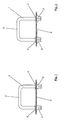
- a U-shaped bracket 1 is shown, which is to be attached to a sheet-metal part 2 of a vehicle body.
- the U-shaped bracket 1 is configured at its two ends in each case as a blind rivet.
- the end portions of the U-shaped bracket 1 are each axially surrounded by a rivet sleeve 3, wherein in each case a cavity between the rivet sleeve 3 and the end portion of the U-shaped bracket 1 is located.
- the rivet sleeves 3 At their the ends of the U-shaped bracket 1 facing the rivet sleeves 3 are connected to the ends of the U-shaped bracket 1, so that the end portions of the U-shaped bracket 1 can serve as a mandrel for the blind rivet.
- the rivet sleeves 3 At the ends pointing away from the ends of the U-shaped bracket 1, the rivet sleeves 3 each have a collar 4 projecting radially outward.
- the setting tool for riveting the U-shaped bracket 1 is supported on the collars 4 of the rivet sleeves 3.
- the middle section 5 of the U-shaped bracket 1 serves as an abutment which is pulled upwardly away from the flat sheet-metal component 2 relative to the collars 4 of the rivet sleeves 3. This will - as in Fig. 2 shown - the rivet sleeves 3 'compressed, so that the U-shaped bracket 1 is positively held by the collars 4 on the one hand and the compressed rivet sleeves 3' on the other hand in the through holes of the sheet metal part 2.
- the U-shaped bracket 1 can be attached only from one side of the sheet metal part 2 at this. It does not have to be welded or screwed on.
- the attachment by riveting is very fast, reliable and inexpensive to produce. There is no additional support plate required.
Landscapes
- Engineering & Computer Science (AREA)
- Health & Medical Sciences (AREA)
- Child & Adolescent Psychology (AREA)
- General Health & Medical Sciences (AREA)
- Aviation & Aerospace Engineering (AREA)
- Transportation (AREA)
- Mechanical Engineering (AREA)
- Connection Of Plates (AREA)
- Seats For Vehicles (AREA)
- Insertion Pins And Rivets (AREA)
Description
- Die Erfindung betrifft ein Kraftfahrzeug mit einem U-förmigen Bügel nach dem Oberbegriff des Patentanspruchs 1.
- Viele heutige Kraftfahrzeuge weisen einen U-förmigen Bügel auf, der mit seinen beiden Enden an einem flächigen Blechbauteil befestigt ist. Ein solcher U-förmiger Bügel kann beispielsweise zur Befestigung eines Kindersitzes im Kraftfahrzeug gemäß dem sogenannten Isofix-Standard dienen, er kann als Schließbügel für ein Schloss einer Tür oder Klappe des Kraftfahrzeugs zum Einsatz kommen, er kann im Kofferraum zur Sicherung von Ladegut vorgesehen sein, etc. Üblicherweise ist der U-förmige Bügel zur Befestigung an dem flächigen Blechbauteil mit einer Trägerplatte verbunden, die flächig an dem Blechbauteil anliegt. Die Trägerplatte wiederum ist mit dem Blechbauteil verschweißt, verschraubt oder vernietet.
- Aus der
EP 0 642 955 A1 ist bereits ein Kraftfahrzeug mit einem U-förmigen Bügel bekannt, der mit beiden Enden an einem flächigen Blechbauteil befestigbar ist. - Ferner ist aus der
DE 295 09 439 U1 ein Stanzniet mit einem am Nietkopf angeformten Gewindebolzen bekannt. Darüber hinaus ist aus derDE 41 00 709 A1 eine Blindnietmutter mit einem Zugdorn bekannt, wobei der Zugdorn als vormontierte Kopfschraube ausgebildet ist, deren Kopf das Widerlager für ein Setzwerkzeug bildet. - Aufgabe der Erfindung ist es, ein Kraftfahrzeug mit einem U-förmigen Bügel zu schaffen, der auf einfache Weise an einem Blechbauteil befestigbar ist.
- Diese Aufgabe wird mit einem Kraftfahrzeug mit einem U-förmigen Bügel mit den Merkmalen des Patentanspruchs 1 gelöst.
- Erfindungsgemäß ist der U-förmige Bügel an seinen beiden Enden jeweils als Blindniet ausgestaltet, wobei der U-förmige Bügel selber den Zugdorn der Blindnieten bildet. Ein Blindniet ist eine spezielle Form von Niet, welche nur den Zugang zu einer Seite der zu verbindenden Bauteile erfordert und mit einem speziellen Setzwerkzeug befestigt wird. Beim Blindnieten erfolgt der Fügevorgang von nur einer Seite des Bauteils aus. Der Blindniet wird durch die Bohrung eingeführt, anschließend wird der am Kopf herausragende Zugdorn mit dem Setzwerkzeug herausgezogen. Dies führt zu einer Stauchung und somit zu einer Aufweitung des Niets hinter der Bohrung. Als Zugdorne dienen erfindungsgemäß die Endabschnitte des U-förmigen Bügels.
- Der erfindungsgemäße U-förmige Bügel wird zur Befestigung an dem Blechbauteil mit seinen beiden Enden durch je ein Durchgangsloch in dem Blechbauteil hindurch gesteckt. Anschließend werden die Enden in den Durchgangslöchern wie normale Blindniete vernietet. Als Zugdorne dienen dabei die Endabschnitte des U-förmigen Bügels. Als günstiger Angriffspunkt zum Herausziehen der Zugdorne kann beispielsweise der mittlere Abschnitt des U-förmigen Bügels dienen.
- Weitere vorteilhafte Ausgestaltungen sind Gegenstand von Unteransprüchen.
- In der Zeichnung ist ein Ausführungsbeispiel der Erfindung dargestellt, anhand dessen die Erfindung im Folgenden näher beschrieben wird. Die einzelnen Figuren zeigen in schematischer Darstellungsweise:
- Fig. 1
- einen U-förmigen Bügel, der mit seinen beiden Enden durch zwei Durchgangslöcher in einem flächigen Blechbauteil einer Karosserie eines Kraftfahrzeugs durchgesteckt ist, und
- Fig. 2
- die Anordnung aus
Fig. 1 nach dem Vernieten des U-förmigen Bügels mit dem Blechbauteil. - In
Fig. 1 ist ein U-förmiger Bügel 1 dargestellt, der an einem flächigen Blechbauteil 2 einer Fahrzeugkarosserie befestigt werden soll. Dazu ist der U-förmige Bügel 1 an seinen beiden Enden jeweils als Blindniet ausgestaltet. Die Endabschnitte des U-förmigen Bügels 1 sind jeweils mit einer Niethülse 3 axial umgeben, wobei sich jeweils ein Hohlraum zwischen der Niethülse 3 und dem Endabschnitt des U-förmigen Bügels 1 befindet. An ihren den Enden des U-förmigen Bügels 1 zugewandten Enden sind die Niethülsen 3 mit den Enden des U-förmigen Bügels 1 verbunden, sodass die Endabschnitte des U-förmigen Bügels 1 als Zugdorn für den Blindniet dienen können. An den von den Enden des U-förmigen Bügels 1 wegweisenden Enden weisen die Niethülsen 3 jeweils einen radial nach außen abstehenden Kragen 4 auf. - Zum Vernieten des U-förmigen Bügels 1 mit dem Blechbauteil 2 werden nun die Enden des U-förmigen Bügels 1 - wie in
Fig. 1 gezeigt - jeweils durch ein Durchgangsloch in dem Blechbauteil 2 durchgesteckt, bis die Krägen 4 der Niethülsen 3 auf dem Blechbauteil 2 anliegen. Der Durchmesser der Durchgangslöcher entspricht dabei etwa dem Außendurchmesser der Niethülsen 3. - Das Setzwerkzeug zum Vernieten des U-förmigen Bügels 1 stützt sich auf den Krägen 4 der Niethülsen 3 ab. Der mittlere Abschnitt 5 des U-förmigen Bügels 1 dient als Widerlager, das relativ zu den Krägen 4 der Niethülsen 3 nach oben weg von dem flächigen Blechbauteil 2 gezogen wird. Dadurch werden - wie in
Fig. 2 gezeigt - die Niethülsen 3' gestaucht, sodass der U-förmige Bügel 1 formschlüssig durch die Krägen 4 einerseits und die gestauchten Niethülsen 3' andererseits in den Durchgangslöchern des Blechbauteils 2 gehalten ist. - Auf diese Weise kann der der U-förmige Bügel 1 ausschließlich von einer Seite des Blechbauteils 2 an diesem befestigt werden. Er muss nicht angeschweißt oder angeschraubt werden. Die Befestigung durch das Vernieten ist sehr schnell, prozesssicher und kostengünstig herstellbar. Es ist keine zusätzliche Trägerplatte erforderlich.
Claims (6)
- Kraftfahrzeug mit einem U-förmigen Bügel (1), der mit beiden Enden an einem flächigen Blechbauteil (2) befestigbar ist, dadurch gekennzeichnet, dass der U-förmige Bügel (1) an seinen beiden Enden jeweils als Blindniet ausgestaltet ist, wobei der U-förmige Bügel (1) selber den Zugdorn der Blindnieten bildet.
- Kraftfahrzeug nach Anspruch 1, dadurch gekennzeichnet, dass jeweils eine Niethülse die Endabschnitte des U-förmigen Bügels (1) axial umgibt, wobei sich jeweils ein Hohlraum zwischen der Niethülse (3) und dem Endabschnitt des U-förmigen Bügels (1) befindet.
- Kraftfahrzeug nach Anspruch 2, dadurch gekennzeichnet, dass die Niethülsen (3) an ihren von den Enden des U-förmigen Bügels (1) wegweisenden Enden jeweils einen radial nach außen abstehenden Kragen (4) aufweisen.
- Kraftfahrzeug nach Anspruch 2 oder 3, gekennzeichnet, dass die Niethülsen (3) an ihren den Enden des U-förmigen Bügels (1) zugewandten Enden mit den Enden des U-förmigen Bügels (1) verbunden sind.
- Kraftfahrzeug nach einem der vorhergehenden Ansprüche, dadurch gekennzeichnet, dass der mittlere Abschnitt (5) des U-förmigen Bügels (1) als Widerlager für ein Setzwerkzeug dient.
- Kraftfahrzeug nach einem der vorhergehenden Ansprüche, dadurch gekennzeichnet, dass das Blechbauteil (2) zur Befestigung des U-förmigen Bügels (1) zwei Durchgangslöcher aufweist, deren Durchmesser etwa dem Außendurchmesser der Niethülsen (3) entsprechen.
Applications Claiming Priority (2)
| Application Number | Priority Date | Filing Date | Title |
|---|---|---|---|
| DE102009024453A DE102009024453A1 (de) | 2009-06-10 | 2009-06-10 | Kraftfahrzeug mit einem U-förmigen Bügel |
| PCT/EP2010/058041 WO2010142704A1 (de) | 2009-06-10 | 2010-06-09 | Kraftfahrzeug mit einem u-förmigen bügel |
Publications (2)
| Publication Number | Publication Date |
|---|---|
| EP2440428A1 EP2440428A1 (de) | 2012-04-18 |
| EP2440428B1 true EP2440428B1 (de) | 2013-04-03 |
Family
ID=42667912
Family Applications (1)
| Application Number | Title | Priority Date | Filing Date |
|---|---|---|---|
| EP10722712A Active EP2440428B1 (de) | 2009-06-10 | 2010-06-09 | Kraftfahrzeug mit einem u-förmigen bügel |
Country Status (5)
| Country | Link |
|---|---|
| US (1) | US8740289B2 (de) |
| EP (1) | EP2440428B1 (de) |
| CN (1) | CN102574482B (de) |
| DE (1) | DE102009024453A1 (de) |
| WO (1) | WO2010142704A1 (de) |
Families Citing this family (5)
| Publication number | Priority date | Publication date | Assignee | Title |
|---|---|---|---|---|
| DE202013007803U1 (de) * | 2013-09-03 | 2014-12-05 | GM Global Technology Operations LLC (n. d. Gesetzen des Staates Delaware) | Verankerungsvorrichtung |
| JP6349573B2 (ja) * | 2013-12-27 | 2018-07-04 | 三井金属アクト株式会社 | ストライカ |
| JP6582574B2 (ja) * | 2015-06-11 | 2019-10-02 | トヨタ紡織株式会社 | 乗物用シート |
| CN108909550A (zh) * | 2017-03-22 | 2018-11-30 | 标致雪铁龙集团 | 汽车儿童座椅挂钩安装支架及汽车 |
| CN108705962A (zh) * | 2018-07-05 | 2018-10-26 | 泰姆勒汽车部件(苏州)有限公司 | 汽车安全座椅 |
Family Cites Families (23)
| Publication number | Priority date | Publication date | Assignee | Title |
|---|---|---|---|---|
| US2239798A (en) * | 1939-06-01 | 1941-04-29 | Tinnerman Products Inc | Handle or knob mounting and the like |
| US3145050A (en) * | 1963-09-10 | 1964-08-18 | Nat Seating Co | Flexible handle |
| GB1517624A (en) * | 1975-02-25 | 1978-07-12 | Nichiei Bussan Co Ltd | Blind rivet |
| DE3021552A1 (de) * | 1980-06-07 | 1982-01-07 | Gebr. Happich Gmbh, 5600 Wuppertal | Befestigungsvorrichtung fuer haltegriffe, armlehnen o.dgl. an der karosseriewand von fahrzeugen |
| US4912809A (en) * | 1985-01-11 | 1990-04-03 | Kawneer Company, Inc. | Tandem cone bolt anchor mounting assembly |
| DE4100709A1 (de) | 1991-01-11 | 1992-07-16 | Emhart Inc | Blindnietmutter mit zugdorn |
| DE4129864A1 (de) * | 1991-09-07 | 1993-03-18 | Mannesmann Kienzle Gmbh | Befestigungsvorrichtung fuer ein elektronisches geraet |
| DE9213169U1 (de) * | 1992-09-30 | 1993-01-28 | Mannesmann Kienzle GmbH, 7730 Villingen-Schwenningen | Schraubverbindung zum justierbaren Befestigen eines Gerätes oder eines Geräteträgers an einer Unterlage |
| DE4331278A1 (de) * | 1993-09-15 | 1995-03-16 | Ieper Ind Nv | Rückhaltevorrichtung |
| JP2606466Y2 (ja) * | 1993-09-27 | 2000-11-06 | オートリブ デベロップメント アクテボラゲット | エアバッグ装置 |
| US5519917A (en) * | 1994-08-05 | 1996-05-28 | Cambridge Industries, Inc. | Mounting device for a front mounted removable handle and the like |
| DE9412752U1 (de) * | 1994-08-06 | 1994-10-13 | Ulrich, Dieter, 64759 Sensbachtal | Halterung für den Transport von Fahrrädern im Kraftfahrzeuginnern |
| JP3301255B2 (ja) * | 1995-03-06 | 2002-07-15 | 日産自動車株式会社 | 車両用トランクネット配設構造 |
| DE29509439U1 (de) | 1995-06-09 | 1995-08-24 | Böllhoff GmbH Verbindungs- und Montagetechnik, 33649 Bielefeld | Stanzniet, insbesondere mit einem am Nietkopf angeformten Gewindebolzen |
| US5938368A (en) * | 1997-10-20 | 1999-08-17 | Loctec Corporation | Fastening device including a collapsible washer |
| US6176660B1 (en) * | 1998-07-24 | 2001-01-23 | Trw Inc. | Releasable fastener with lateral stabilizing brace members and latch legs carrying fastener insertion guide |
| DE10118935C2 (de) * | 2001-04-18 | 2003-07-03 | Kasselbauer Ralf | Befestigungsmittel zum Verbinden zweier Bauteile miteinander |
| JP3992095B2 (ja) * | 2002-01-09 | 2007-10-17 | 株式会社ニフコ | アシストグリップ |
| DE10333630B4 (de) * | 2002-12-11 | 2004-10-21 | Uebler Gmbh | Befestigungseinrichtung für ein Transportgut sowie deren Verwendung insbesondere für ein Fahrrad |
| DE10305190B3 (de) * | 2003-02-08 | 2004-08-05 | Daimlerchrysler Ag | Gehäuse zum Anbringen an einem Fahrzeugbauteil |
| DE10311805B4 (de) * | 2003-03-12 | 2008-06-26 | Bos Gmbh & Co. Kg | Arretierungsvorrichtung für Aufnahmemodul |
| DE10343144A1 (de) * | 2003-09-18 | 2005-01-27 | Daimlerchrysler Ag | Transporthalterung für Fahrzeuge |
| WO2009152478A1 (en) * | 2008-06-12 | 2009-12-17 | Milsco Manufacturing, A Unit Of Jason Incorporated | Vehicle seat assembly |
-
2009
- 2009-06-10 DE DE102009024453A patent/DE102009024453A1/de not_active Withdrawn
-
2010
- 2010-06-09 CN CN201080025975.XA patent/CN102574482B/zh not_active Expired - Fee Related
- 2010-06-09 WO PCT/EP2010/058041 patent/WO2010142704A1/de not_active Ceased
- 2010-06-09 EP EP10722712A patent/EP2440428B1/de active Active
-
2011
- 2011-12-09 US US13/315,993 patent/US8740289B2/en active Active
Also Published As
| Publication number | Publication date |
|---|---|
| US20120107071A1 (en) | 2012-05-03 |
| US8740289B2 (en) | 2014-06-03 |
| DE102009024453A1 (de) | 2010-12-16 |
| CN102574482A (zh) | 2012-07-11 |
| WO2010142704A1 (de) | 2010-12-16 |
| CN102574482B (zh) | 2014-07-09 |
| EP2440428A1 (de) | 2012-04-18 |
Similar Documents
| Publication | Publication Date | Title |
|---|---|---|
| EP2037131B1 (de) | Hybridbauteil | |
| EP3036443B1 (de) | Verfahren zum verbinden von bauteilen sowie baugruppe | |
| DE102010017296A1 (de) | Blindniet und Befestigungsanordnung mit einem Blindniet | |
| EP3157770B1 (de) | Radträger eines fahrzeuges mit einer klemmsitz-verbindung | |
| DE4417279C2 (de) | Vorrichtung zum formschlüssigen Verbinden zumindest eines ersten drehbaren Bauteils und eines zweiten drehfesten Bauteils durch ein Verbindungsteil | |
| EP2440428A1 (de) | Kraftfahrzeug mit einem u-förmigen bügel | |
| EP2128360B1 (de) | Fangbügel eines Fahrzeugschlosses und Verschlussanordnung | |
| WO2012072152A1 (de) | Befestigungsvorrichtung und befestigungsbaugruppe zur befestigung eines gasgenerators und fahrzeuginsassenrückhaltesystem | |
| DE10247377C1 (de) | Abschleppöse für ein Kraftfahrzeug | |
| DE102018116271A9 (de) | Verfahren zum Verbinden | |
| EP1187995B1 (de) | Fügeverbindung und ein verfahren zur herstellung derselben, sowie lenksäule von kraftfahrzeugen mit einer solchen fügeverbindung | |
| DE102009014206B4 (de) | Cockpitquerträger | |
| EP3054182B1 (de) | Verfahren zur herstellung einer fügeverbindung zwischen einem gelenkgehäuse und einem anbindungsbauteil, sowie verfahrensgemäss hergestelltes fahrwerkbauteil | |
| DE102008056407B4 (de) | Schließvorrichtung für Klappen | |
| DE202016106796U1 (de) | Fahrzeugsitz | |
| DE102006022382A1 (de) | Vorrichtung und Verfahren zur Befestigung eines Wischermotors an ein Wischergestänge | |
| DE102011013389A1 (de) | Verbindungsanordnung zweier zumindest im Wesentlichen aus einem Leichtmetall gebildeten Bauteile | |
| DE102021125436B3 (de) | Automobilscharnier | |
| DE102020122941A1 (de) | Antrieb für ein Verschlusselement eines Kraftfahrzeugs | |
| DE102016006845A1 (de) | Verbindung von Außenverkleidungsbauteilen einer Kraftfahrzeugkarosserie | |
| EP2857700B1 (de) | Verfahren zum Befestigen eines ersten Bauteils an einem zweiten Bauteil eines Kraftwagens sowie Befestigungsanordnung eines ersten Bauteils an einem zweiten Bauteil eines Kraftwagens | |
| WO2016050233A1 (de) | Kraftfahrzeugtürschloss | |
| EP2597283B1 (de) | Variable Turbinengeometrie | |
| EP2134486B1 (de) | Lagerbolzen-bauteil und fahrzeugsitz mit einem lagerbolzen-bauteil | |
| DE102019117086A1 (de) | Befestigungseinheit |
Legal Events
| Date | Code | Title | Description |
|---|---|---|---|
| PUAI | Public reference made under article 153(3) epc to a published international application that has entered the european phase |
Free format text: ORIGINAL CODE: 0009012 |
|
| 17P | Request for examination filed |
Effective date: 20111025 |
|
| AK | Designated contracting states |
Kind code of ref document: A1 Designated state(s): AL AT BE BG CH CY CZ DE DK EE ES FI FR GB GR HR HU IE IS IT LI LT LU LV MC MK MT NL NO PL PT RO SE SI SK SM TR |
|
| DAX | Request for extension of the european patent (deleted) | ||
| GRAJ | Information related to disapproval of communication of intention to grant by the applicant or resumption of examination proceedings by the epo deleted |
Free format text: ORIGINAL CODE: EPIDOSDIGR1 |
|
| GRAP | Despatch of communication of intention to grant a patent |
Free format text: ORIGINAL CODE: EPIDOSNIGR1 |
|
| GRAS | Grant fee paid |
Free format text: ORIGINAL CODE: EPIDOSNIGR3 |
|
| GRAA | (expected) grant |
Free format text: ORIGINAL CODE: 0009210 |
|
| AK | Designated contracting states |
Kind code of ref document: B1 Designated state(s): AL AT BE BG CH CY CZ DE DK EE ES FI FR GB GR HR HU IE IS IT LI LT LU LV MC MK MT NL NO PL PT RO SE SI SK SM TR |
|
| REG | Reference to a national code |
Ref country code: GB Ref legal event code: FG4D Free format text: NOT ENGLISH |
|
| REG | Reference to a national code |
Ref country code: CH Ref legal event code: EP Ref country code: AT Ref legal event code: REF Ref document number: 604488 Country of ref document: AT Kind code of ref document: T Effective date: 20130415 |
|
| REG | Reference to a national code |
Ref country code: IE Ref legal event code: FG4D Free format text: LANGUAGE OF EP DOCUMENT: GERMAN |
|
| REG | Reference to a national code |
Ref country code: DE Ref legal event code: R096 Ref document number: 502010002866 Country of ref document: DE Effective date: 20130529 |
|
| PG25 | Lapsed in a contracting state [announced via postgrant information from national office to epo] |
Ref country code: SI Free format text: LAPSE BECAUSE OF FAILURE TO SUBMIT A TRANSLATION OF THE DESCRIPTION OR TO PAY THE FEE WITHIN THE PRESCRIBED TIME-LIMIT Effective date: 20130403 |
|
| REG | Reference to a national code |
Ref country code: NL Ref legal event code: VDEP Effective date: 20130403 |
|
| REG | Reference to a national code |
Ref country code: LT Ref legal event code: MG4D |
|
| PG25 | Lapsed in a contracting state [announced via postgrant information from national office to epo] |
Ref country code: IS Free format text: LAPSE BECAUSE OF FAILURE TO SUBMIT A TRANSLATION OF THE DESCRIPTION OR TO PAY THE FEE WITHIN THE PRESCRIBED TIME-LIMIT Effective date: 20130803 Ref country code: FI Free format text: LAPSE BECAUSE OF FAILURE TO SUBMIT A TRANSLATION OF THE DESCRIPTION OR TO PAY THE FEE WITHIN THE PRESCRIBED TIME-LIMIT Effective date: 20130403 Ref country code: LT Free format text: LAPSE BECAUSE OF FAILURE TO SUBMIT A TRANSLATION OF THE DESCRIPTION OR TO PAY THE FEE WITHIN THE PRESCRIBED TIME-LIMIT Effective date: 20130403 Ref country code: PT Free format text: LAPSE BECAUSE OF FAILURE TO SUBMIT A TRANSLATION OF THE DESCRIPTION OR TO PAY THE FEE WITHIN THE PRESCRIBED TIME-LIMIT Effective date: 20130805 Ref country code: NL Free format text: LAPSE BECAUSE OF FAILURE TO SUBMIT A TRANSLATION OF THE DESCRIPTION OR TO PAY THE FEE WITHIN THE PRESCRIBED TIME-LIMIT Effective date: 20130403 Ref country code: GR Free format text: LAPSE BECAUSE OF FAILURE TO SUBMIT A TRANSLATION OF THE DESCRIPTION OR TO PAY THE FEE WITHIN THE PRESCRIBED TIME-LIMIT Effective date: 20130704 Ref country code: SE Free format text: LAPSE BECAUSE OF FAILURE TO SUBMIT A TRANSLATION OF THE DESCRIPTION OR TO PAY THE FEE WITHIN THE PRESCRIBED TIME-LIMIT Effective date: 20130403 Ref country code: ES Free format text: LAPSE BECAUSE OF FAILURE TO SUBMIT A TRANSLATION OF THE DESCRIPTION OR TO PAY THE FEE WITHIN THE PRESCRIBED TIME-LIMIT Effective date: 20130714 Ref country code: NO Free format text: LAPSE BECAUSE OF FAILURE TO SUBMIT A TRANSLATION OF THE DESCRIPTION OR TO PAY THE FEE WITHIN THE PRESCRIBED TIME-LIMIT Effective date: 20130703 |
|
| PG25 | Lapsed in a contracting state [announced via postgrant information from national office to epo] |
Ref country code: BG Free format text: LAPSE BECAUSE OF FAILURE TO SUBMIT A TRANSLATION OF THE DESCRIPTION OR TO PAY THE FEE WITHIN THE PRESCRIBED TIME-LIMIT Effective date: 20130703 Ref country code: HR Free format text: LAPSE BECAUSE OF FAILURE TO SUBMIT A TRANSLATION OF THE DESCRIPTION OR TO PAY THE FEE WITHIN THE PRESCRIBED TIME-LIMIT Effective date: 20130403 Ref country code: PL Free format text: LAPSE BECAUSE OF FAILURE TO SUBMIT A TRANSLATION OF THE DESCRIPTION OR TO PAY THE FEE WITHIN THE PRESCRIBED TIME-LIMIT Effective date: 20130403 Ref country code: CY Free format text: LAPSE BECAUSE OF FAILURE TO SUBMIT A TRANSLATION OF THE DESCRIPTION OR TO PAY THE FEE WITHIN THE PRESCRIBED TIME-LIMIT Effective date: 20130403 Ref country code: LV Free format text: LAPSE BECAUSE OF FAILURE TO SUBMIT A TRANSLATION OF THE DESCRIPTION OR TO PAY THE FEE WITHIN THE PRESCRIBED TIME-LIMIT Effective date: 20130403 |
|
| BERE | Be: lapsed |
Owner name: BAYERISCHE MOTOREN WERKE A.G. Effective date: 20130630 |
|
| PG25 | Lapsed in a contracting state [announced via postgrant information from national office to epo] |
Ref country code: CZ Free format text: LAPSE BECAUSE OF FAILURE TO SUBMIT A TRANSLATION OF THE DESCRIPTION OR TO PAY THE FEE WITHIN THE PRESCRIBED TIME-LIMIT Effective date: 20130403 Ref country code: MC Free format text: LAPSE BECAUSE OF FAILURE TO SUBMIT A TRANSLATION OF THE DESCRIPTION OR TO PAY THE FEE WITHIN THE PRESCRIBED TIME-LIMIT Effective date: 20130403 Ref country code: EE Free format text: LAPSE BECAUSE OF FAILURE TO SUBMIT A TRANSLATION OF THE DESCRIPTION OR TO PAY THE FEE WITHIN THE PRESCRIBED TIME-LIMIT Effective date: 20130403 Ref country code: DK Free format text: LAPSE BECAUSE OF FAILURE TO SUBMIT A TRANSLATION OF THE DESCRIPTION OR TO PAY THE FEE WITHIN THE PRESCRIBED TIME-LIMIT Effective date: 20130403 Ref country code: SK Free format text: LAPSE BECAUSE OF FAILURE TO SUBMIT A TRANSLATION OF THE DESCRIPTION OR TO PAY THE FEE WITHIN THE PRESCRIBED TIME-LIMIT Effective date: 20130403 |
|
| PLBE | No opposition filed within time limit |
Free format text: ORIGINAL CODE: 0009261 |
|
| STAA | Information on the status of an ep patent application or granted ep patent |
Free format text: STATUS: NO OPPOSITION FILED WITHIN TIME LIMIT |
|
| PG25 | Lapsed in a contracting state [announced via postgrant information from national office to epo] |
Ref country code: RO Free format text: LAPSE BECAUSE OF FAILURE TO SUBMIT A TRANSLATION OF THE DESCRIPTION OR TO PAY THE FEE WITHIN THE PRESCRIBED TIME-LIMIT Effective date: 20130403 |
|
| 26N | No opposition filed |
Effective date: 20140106 |
|
| REG | Reference to a national code |
Ref country code: IE Ref legal event code: MM4A |
|
| PG25 | Lapsed in a contracting state [announced via postgrant information from national office to epo] |
Ref country code: BE Free format text: LAPSE BECAUSE OF NON-PAYMENT OF DUE FEES Effective date: 20130630 |
|
| REG | Reference to a national code |
Ref country code: DE Ref legal event code: R097 Ref document number: 502010002866 Country of ref document: DE Effective date: 20140106 |
|
| PG25 | Lapsed in a contracting state [announced via postgrant information from national office to epo] |
Ref country code: IE Free format text: LAPSE BECAUSE OF NON-PAYMENT OF DUE FEES Effective date: 20130609 |
|
| REG | Reference to a national code |
Ref country code: CH Ref legal event code: PL |
|
| PG25 | Lapsed in a contracting state [announced via postgrant information from national office to epo] |
Ref country code: MT Free format text: LAPSE BECAUSE OF FAILURE TO SUBMIT A TRANSLATION OF THE DESCRIPTION OR TO PAY THE FEE WITHIN THE PRESCRIBED TIME-LIMIT Effective date: 20130403 |
|
| PG25 | Lapsed in a contracting state [announced via postgrant information from national office to epo] |
Ref country code: CH Free format text: LAPSE BECAUSE OF NON-PAYMENT OF DUE FEES Effective date: 20140630 Ref country code: LI Free format text: LAPSE BECAUSE OF NON-PAYMENT OF DUE FEES Effective date: 20140630 |
|
| PG25 | Lapsed in a contracting state [announced via postgrant information from national office to epo] |
Ref country code: SM Free format text: LAPSE BECAUSE OF FAILURE TO SUBMIT A TRANSLATION OF THE DESCRIPTION OR TO PAY THE FEE WITHIN THE PRESCRIBED TIME-LIMIT Effective date: 20130403 |
|
| PG25 | Lapsed in a contracting state [announced via postgrant information from national office to epo] |
Ref country code: TR Free format text: LAPSE BECAUSE OF FAILURE TO SUBMIT A TRANSLATION OF THE DESCRIPTION OR TO PAY THE FEE WITHIN THE PRESCRIBED TIME-LIMIT Effective date: 20130403 |
|
| PG25 | Lapsed in a contracting state [announced via postgrant information from national office to epo] |
Ref country code: MK Free format text: LAPSE BECAUSE OF FAILURE TO SUBMIT A TRANSLATION OF THE DESCRIPTION OR TO PAY THE FEE WITHIN THE PRESCRIBED TIME-LIMIT Effective date: 20130403 Ref country code: LU Free format text: LAPSE BECAUSE OF NON-PAYMENT OF DUE FEES Effective date: 20130609 Ref country code: HU Free format text: LAPSE BECAUSE OF FAILURE TO SUBMIT A TRANSLATION OF THE DESCRIPTION OR TO PAY THE FEE WITHIN THE PRESCRIBED TIME-LIMIT; INVALID AB INITIO Effective date: 20100609 |
|
| REG | Reference to a national code |
Ref country code: FR Ref legal event code: PLFP Year of fee payment: 7 |
|
| REG | Reference to a national code |
Ref country code: AT Ref legal event code: MM01 Ref document number: 604488 Country of ref document: AT Kind code of ref document: T Effective date: 20150609 |
|
| PG25 | Lapsed in a contracting state [announced via postgrant information from national office to epo] |
Ref country code: AT Free format text: LAPSE BECAUSE OF NON-PAYMENT OF DUE FEES Effective date: 20150609 |
|
| REG | Reference to a national code |
Ref country code: FR Ref legal event code: PLFP Year of fee payment: 8 |
|
| REG | Reference to a national code |
Ref country code: FR Ref legal event code: PLFP Year of fee payment: 9 |
|
| PG25 | Lapsed in a contracting state [announced via postgrant information from national office to epo] |
Ref country code: AL Free format text: LAPSE BECAUSE OF FAILURE TO SUBMIT A TRANSLATION OF THE DESCRIPTION OR TO PAY THE FEE WITHIN THE PRESCRIBED TIME-LIMIT Effective date: 20130403 |
|
| PGFP | Annual fee paid to national office [announced via postgrant information from national office to epo] |
Ref country code: GB Payment date: 20220623 Year of fee payment: 13 |
|
| PGFP | Annual fee paid to national office [announced via postgrant information from national office to epo] |
Ref country code: FR Payment date: 20220622 Year of fee payment: 13 |
|
| PGFP | Annual fee paid to national office [announced via postgrant information from national office to epo] |
Ref country code: IT Payment date: 20220630 Year of fee payment: 13 |
|
| P01 | Opt-out of the competence of the unified patent court (upc) registered |
Effective date: 20230502 |
|
| GBPC | Gb: european patent ceased through non-payment of renewal fee |
Effective date: 20230609 |
|
| PG25 | Lapsed in a contracting state [announced via postgrant information from national office to epo] |
Ref country code: GB Free format text: LAPSE BECAUSE OF NON-PAYMENT OF DUE FEES Effective date: 20230609 |
|
| PG25 | Lapsed in a contracting state [announced via postgrant information from national office to epo] |
Ref country code: FR Free format text: LAPSE BECAUSE OF NON-PAYMENT OF DUE FEES Effective date: 20230630 |
|
| PG25 | Lapsed in a contracting state [announced via postgrant information from national office to epo] |
Ref country code: IT Free format text: LAPSE BECAUSE OF NON-PAYMENT OF DUE FEES Effective date: 20230609 |
|
| PGFP | Annual fee paid to national office [announced via postgrant information from national office to epo] |
Ref country code: DE Payment date: 20250605 Year of fee payment: 16 |