EP2440353B1 - Schneidwerkzeug - Google Patents
Schneidwerkzeug Download PDFInfo
- Publication number
- EP2440353B1 EP2440353B1 EP10732244A EP10732244A EP2440353B1 EP 2440353 B1 EP2440353 B1 EP 2440353B1 EP 10732244 A EP10732244 A EP 10732244A EP 10732244 A EP10732244 A EP 10732244A EP 2440353 B1 EP2440353 B1 EP 2440353B1
- Authority
- EP
- European Patent Office
- Prior art keywords
- hole
- cutting tool
- bearing surface
- respect
- segment
- Prior art date
- Legal status (The legal status is an assumption and is not a legal conclusion. Google has not performed a legal analysis and makes no representation as to the accuracy of the status listed.)
- Active
Links
Images

Classifications
-
- B—PERFORMING OPERATIONS; TRANSPORTING
- B23—MACHINE TOOLS; METAL-WORKING NOT OTHERWISE PROVIDED FOR
- B23C—MILLING
- B23C5/00—Milling-cutters
- B23C5/16—Milling-cutters characterised by physical features other than shape
- B23C5/20—Milling-cutters characterised by physical features other than shape with removable cutter bits or teeth or cutting inserts
- B23C5/22—Securing arrangements for bits or teeth or cutting inserts
- B23C5/2204—Securing arrangements for bits or teeth or cutting inserts with cutting inserts clamped against the walls of the recess in the cutter body by a clamping member acting upon the wall of a hole in the insert
- B23C5/2208—Securing arrangements for bits or teeth or cutting inserts with cutting inserts clamped against the walls of the recess in the cutter body by a clamping member acting upon the wall of a hole in the insert for plate-like cutting inserts
-
- B—PERFORMING OPERATIONS; TRANSPORTING
- B23—MACHINE TOOLS; METAL-WORKING NOT OTHERWISE PROVIDED FOR
- B23B—TURNING; BORING
- B23B27/00—Tools for turning or boring machines; Tools of a similar kind in general; Accessories therefor
- B23B27/14—Cutting tools of which the bits or tips or cutting inserts are of special material
- B23B27/16—Cutting tools of which the bits or tips or cutting inserts are of special material with exchangeable cutting bits or cutting inserts, e.g. able to be clamped
- B23B27/1662—Cutting tools of which the bits or tips or cutting inserts are of special material with exchangeable cutting bits or cutting inserts, e.g. able to be clamped with plate-like cutting inserts clamped against the walls of the recess in the shank by a clamping member acting upon the wall of a hole in the cutting insert
-
- B—PERFORMING OPERATIONS; TRANSPORTING
- B23—MACHINE TOOLS; METAL-WORKING NOT OTHERWISE PROVIDED FOR
- B23B—TURNING; BORING
- B23B2205/00—Fixation of cutting inserts in holders
- B23B2205/04—Fixation screws, bolts or pins of particular form
-
- B—PERFORMING OPERATIONS; TRANSPORTING
- B23—MACHINE TOOLS; METAL-WORKING NOT OTHERWISE PROVIDED FOR
- B23B—TURNING; BORING
- B23B2205/00—Fixation of cutting inserts in holders
- B23B2205/04—Fixation screws, bolts or pins of particular form
- B23B2205/045—Fixation screws, bolts or pins of particular form orientated obliquely to the hole in the insert or to the seating surface
-
- B—PERFORMING OPERATIONS; TRANSPORTING
- B23—MACHINE TOOLS; METAL-WORKING NOT OTHERWISE PROVIDED FOR
- B23C—MILLING
- B23C2200/00—Details of milling cutting inserts
- B23C2200/36—Other features of the milling insert not covered by B23C2200/04 - B23C2200/32
- B23C2200/361—Fixation holes
-
- B—PERFORMING OPERATIONS; TRANSPORTING
- B23—MACHINE TOOLS; METAL-WORKING NOT OTHERWISE PROVIDED FOR
- B23C—MILLING
- B23C2210/00—Details of milling cutters
- B23C2210/16—Fixation of inserts or cutting bits in the tool
- B23C2210/165—Fixation bolts
-
- B—PERFORMING OPERATIONS; TRANSPORTING
- B23—MACHINE TOOLS; METAL-WORKING NOT OTHERWISE PROVIDED FOR
- B23C—MILLING
- B23C2240/00—Details of connections of tools or workpieces
- B23C2240/24—Connections using screws
-
- Y—GENERAL TAGGING OF NEW TECHNOLOGICAL DEVELOPMENTS; GENERAL TAGGING OF CROSS-SECTIONAL TECHNOLOGIES SPANNING OVER SEVERAL SECTIONS OF THE IPC; TECHNICAL SUBJECTS COVERED BY FORMER USPC CROSS-REFERENCE ART COLLECTIONS [XRACs] AND DIGESTS
- Y10—TECHNICAL SUBJECTS COVERED BY FORMER USPC
- Y10T—TECHNICAL SUBJECTS COVERED BY FORMER US CLASSIFICATION
- Y10T407/00—Cutters, for shaping
- Y10T407/19—Rotary cutting tool
- Y10T407/1906—Rotary cutting tool including holder [i.e., head] having seat for inserted tool
- Y10T407/1934—Rotary cutting tool including holder [i.e., head] having seat for inserted tool with separate means to fasten tool to holder
- Y10T407/1936—Apertured tool
-
- Y—GENERAL TAGGING OF NEW TECHNOLOGICAL DEVELOPMENTS; GENERAL TAGGING OF CROSS-SECTIONAL TECHNOLOGIES SPANNING OVER SEVERAL SECTIONS OF THE IPC; TECHNICAL SUBJECTS COVERED BY FORMER USPC CROSS-REFERENCE ART COLLECTIONS [XRACs] AND DIGESTS
- Y10—TECHNICAL SUBJECTS COVERED BY FORMER USPC
- Y10T—TECHNICAL SUBJECTS COVERED BY FORMER US CLASSIFICATION
- Y10T407/00—Cutters, for shaping
- Y10T407/22—Cutters, for shaping including holder having seat for inserted tool
- Y10T407/2272—Cutters, for shaping including holder having seat for inserted tool with separate means to fasten tool to holder
- Y10T407/2274—Apertured tool
- Y10T407/2276—Apertured tool with means projecting through aperture to force tool laterally against reaction surface
- Y10T407/2278—Tilting clamp element and separate means to tilt same
Definitions
- the invention relates to a cutting tool having the features of the preamble of claim 1.
- Such a cutting tool is made EP 1 197 281 A known.
- This known cutting tool is designed as a milling cutter whose tool base body has a plurality of insert seats for supporting one indexable cutting insert each.
- Each indexable insert is fixed to the insert seat by means of a clamping pin in the form of a clamping screw.
- the clamping screw passes through a through hole of the indexable cutting insert and is screwed into a mounting hole in the tool body, wherein the mounting hole extends obliquely to a plane of a bottom surface of the insert seat.
- the hole wall of the through hole has a bearing surface on which a spherical segment-shaped portion of a pin head (designed as a screw head) of the clamping pin or the clamping screw is mounted.
- This mounting of the screw head allows a bracing of the indexable insert even with a dowel pin whose central longitudinal axis is tilted relative to the bottom surface of the insert seat or arranged obliquely.
- the achieved by the ball bearing 360 ° contact (with respect to the center axis of the through hole) between the screw head and the bearing surface of the through hole to have a stabilizing effect on the mounting position of the indexable cutting insert.
- this 360 ° storage is overdetermined and therefore not easy to control in terms of mechanical clamping behavior.
- a milling tool - provided for storage portion of the clamping pin on a spherical segment, the surface of which is interrupted by a Segmentnut.
- the segment groove is incorporated as a groove, groove, recess, recess or the like in the spherical segment.
- the Segmentnut avoids the disadvantages of a 360 ° contact between the bearing portion of the clamping pin and the bearing surface in the through hole, in which a constructive over-determination may affect the storage of the clamping pin and thus the desired tension of the cutting insert. Rather, the Segmentnut causes in the circumferential direction of the bearing surface with respect to the central axis considered an interruption of the contact between the spherical segment as a bearing portion of the clamping pin and the bearing surface of the through hole.
- At least two contact zones are realized by means of the segment groove (viewed in a cross-sectional plane).
- Two contact zones are spaced apart in the circumferential direction and together preferably achieve a radian measure of about 180 °. It can also be more than two Be realized contact zones.
- the number of contact zones is in particular a multiple of two contact zones.
- a plurality of segment grooves are provided. The desired number and the desired radian measure of the contact zones can be achieved with a suitable number and / or geometry of segment grooves.
- contact point generally means a contact zone.
- the contact zones can form punctiform, linear or planar contacts between the spherical segment and the bearing surface.
- segment groove By means of the segment groove can be dispensed with specifically designed projections or the like on the bearing surface to form a multi-point contact. Consequently, even at certain points or sections extremely high mechanical loads of the clamping pin in the mounting position of the clamping pin can be avoided.
- the advantages of supporting a spherical segment are combined with the advantages of multi-point contact, while avoiding the above-described disadvantages.
- the dowel pin can also edit later manufacturing technology easy.
- more complex embodiments of the bearing surface on the cutting insert to form a multi-point contact can be avoided cost-effectively.
- the ball segment is arranged on the pin head of the clamping pin.
- the ball segment forms a portion of the pin head, so that the pin head is used in a proven manner for the transmission of the clamping forces.
- the segment groove is formed closed in a circumferential direction with respect to the central longitudinal axis of the clamping pin. This supports a balance between contact zones and non-contact zones (interruption zones) on the bearing surface in the circumferential direction and a uniform stress on the bearing portion (in particular of the pin head) of the Cocking pin in the circumferential direction. Extreme mechanical load peaks at individual points of the dowel pin are avoided in this way.
- a preferably arranged coaxially to the central longitudinal axis of the clamping pin or the pin head Segmentnut allows a production technology simple provision of Segmentnut on the pin head.
- the spherical segment-shaped portion of the clamping pin is arranged coaxially to the central longitudinal axis of the clamping pin and thereby additionally supports a manufacturing technology simple and cost-effective production of the clamping pin.
- the through hole in the region of the bearing surface is designed such that it tapers in the direction of the bottom surface of the insert seat. This geometry of the through hole allows a mechanically stable mounting of the clamping pin, in particular its pin head, during and after its assembly.
- the through hole has a circular cross section.
- at least the region or section of the through hole having the bearing surface is circular.
- the circular cross-section causes a structurally simple way a uniform stable storage of the clamping pin, even if the cutting insert is used several times due to its plurality of cutting edges.
- the clamping pin and the through hole are dimensioned such that a largest cross section of the ball segment is larger than a smallest cross section of the bearing surface. This ensures a stable investment of the ball segment on the bearing surface. In addition, this dimensioning reliably avoids faulty assembly operations.
- a montage technically simple handling of the clamping pin in the through hole is achieved when the pin head has a cross section, the at most as large as the largest cross section of the spherical segment itself.
- Individual sections of the pin head then have, for example, a cylindrical cross-section whose diameter is at most as large as the diameter of the largest segment of the spherical segment.
- Such a pin head supports the smallest possible dimensioning of the through hole, whereby the stability of the cutting insert is increased.
- a structurally simple design of the through hole and thus of the entire cutting insert is achieved when the bearing surface is rotationally symmetrical to the central axis of the through hole.
- further sections of the hole wall e.g. the entire hole wall or surface - the through hole formed rotationally symmetrical to the central axis.
- the center axis of the through hole is arranged at right angles to a surface or two opposite surfaces of the cutting insert.
- a surface is designed, in particular, as a rake surface or as a bearing surface of the cutting insert facing the bottom surface of the insert seat.
- the central axis of the through hole and the central longitudinal axis of the clamping pin can be arranged at an acute angle to each other.
- the central longitudinal axis of the clamping pin is preferably arranged inclined or obliquely opposite to the bottom surface of the insert seat and the corresponding bearing surface of the cutting insert.
- the clamping pin is cost-effectively designed as a clamping screw with a screw head as a pin head.
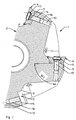
- FIG. 1 illustrated cutting tool -1- is a tool for milling and contains a tool body -2-.
- the head part of the tool body -2- has a plurality of insert seats -3- for storage in each case a replaceable cutting insert -4-.
- the insert seat -3- has a bottom surface -5- and lateral abutment surfaces -6- for positioning of the cutting insert -4-.
- the cutting insert -4- has an octagonal cross-section with correspondingly eight cutting edges -7- ( Fig. 2 ), so that the cutting insert -4- is used several times, each with an active cutting edge -7.
- the cutting insert -4- is penetrated by a first surface -8- (usually the areas of the clamping surface) to its opposite, in the mounting position of the bottom surface -5- facing support surface -9- of a central through-hole -10-.
- the bearing surface -9- is supported in the mounting position of the cutting insert -4- on the bottom surface -5-.
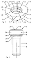
- Each cutting insert -4- is clamped by means of a clamping pin in the form of a clamping screw -11- at the insert seat -3-.
- the clamping screw -11 passes through the center hole -12- having through-hole -10-, the bottom surface -5- and to the bottom surface -5- subsequent receiving hole -13- in the tool body -2-.
- the clamping screw -11- is screwed into the receiving hole -13 -with the tool body -2-.
- an external thread -14- a screw shaft -15- the clamping screw -11- with an internal thread -16- of the receiving hole -13-.
- a central longitudinal axis -17-of the screwed-tightening screw -11- is arranged at an acute angle -W1- to the bottom surface -5-.
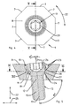
- the screw shaft -15- is followed by a pin head in the form of a screw head -18- ( Fig. 3 ).
- the screw head -18- has a section in the form of a spherical segment -19-.
- the screw head -18- with its spherical segment -19- is mounted on a bearing surface -20-of the through hole -10-.
- the surface of the ball segment 19- is interrupted by a segment groove -21-.
- This segment groove -21- is formed closed in a circumferential direction -22-.
- the segment groove -21- is arranged coaxially to the central longitudinal axis -17-.
- the spherical segment -19- is arranged coaxially to the central longitudinal axis -17-.
- Both the segment groove -21- and the spherical segment -19- are rotationally symmetrical with respect to the central longitudinal axis -17- formed as a rotation axis.
- the hole wall of the through hole -10- has several sections along the central axis -12-.
- a section is formed by the bearing surface -20-, which in cross section according to Fig. 5 seen in the direction of the bottom surface -5- facing the second surface -9- of the cutting insert -4- tapers conically.
- the various portions of the through-hole -10- each have a circular cross-section, as in Fig. 2 and Fig. 4 is recognizable.
- the bearing surface -20- and all other portions of the hole wall of the through hole -10- coaxial and due to their circular cross-section rotationally symmetrical with respect to the central axis -12- formed as a rotation axis.
- the bearing surface -20- and the first surface -8- of the cutting insert -4- are arranged in the axial direction -22-, ie along the central axis -12-, several sections -23- the hole wall of the through-hole -10-. Starting from the first surface -8-the cross-sections of these sections -23- taper in the direction of the bearing surface -20- (FIG. Fig. 5 ). Between the bearing surface -20- and the bearing surface -9- of the cutting insert -4- are several sections -24- the hole wall. The cross sections of these sections are flared in the axial direction -22- either constant or in the direction of the second surface -9-.
- the through hole has a so-called trumpet hole for receiving the clamping screw -11- or its screw head -18-.
- the sections -24- provide sufficient radial clearance in the radial direction -25- for a clamping screw -11- which is mounted with its central longitudinal axis -17- obliquely or at an acute angle -W2- to the central axis -12- of the through-hole -10 ,
- the angle -W2-: -W2- 90 ° -W1- applies here.
- the central axis -12- is arranged approximately at right angles to the first surface -8- and the opposite support surface -9-.
- the largest cross-section -26- of the spherical segment -19- is larger than the smallest cross-section -27- of the bearing surface -20- of the through-hole -10-.
- the head section -28- of the screw head -18- immediately adjoining this largest cross-section -26- is of cylindrical design with a diameter which corresponds approximately to the diameter of the largest cross-section -26- ( Fig. 3 ).
- a between the cylindrical head portion -28- and a free top surface -29- of the screw head -18- arranged portion of the screw head -18- is conically tapered.
- the free top surface -29- is the screw shaft -15- axially facing away from the outer surface of the screw head -18-.
- Interruption zones -31- the segment groove -21- is effective as a contact interruption between the spherical segment -19- and the bearing surface -20-.
- two longer contact zones -30- and at the same time a clearly defined bearing of Kugelsegementes -19- the clamping screw -11- realized.
Landscapes
- Engineering & Computer Science (AREA)
- Mechanical Engineering (AREA)
- Milling Processes (AREA)
- Cutting Tools, Boring Holders, And Turrets (AREA)
Priority Applications (1)
| Application Number | Priority Date | Filing Date | Title |
|---|---|---|---|
| PL10732244T PL2440353T3 (pl) | 2009-06-10 | 2010-06-08 | Narzędzie skrawające |
Applications Claiming Priority (2)
| Application Number | Priority Date | Filing Date | Title |
|---|---|---|---|
| AT0036109U AT11470U1 (de) | 2009-06-10 | 2009-06-10 | Schneidwerkzeug |
| PCT/AT2010/000199 WO2010141966A1 (de) | 2009-06-10 | 2010-06-08 | Schneidwerkzeug |
Publications (2)
| Publication Number | Publication Date |
|---|---|
| EP2440353A1 EP2440353A1 (de) | 2012-04-18 |
| EP2440353B1 true EP2440353B1 (de) | 2013-03-20 |
Family
ID=42676723
Family Applications (1)
| Application Number | Title | Priority Date | Filing Date |
|---|---|---|---|
| EP10732244A Active EP2440353B1 (de) | 2009-06-10 | 2010-06-08 | Schneidwerkzeug |
Country Status (10)
| Country | Link |
|---|---|
| US (1) | US8950983B2 (enExample) |
| EP (1) | EP2440353B1 (enExample) |
| JP (1) | JP5579260B2 (enExample) |
| KR (1) | KR101649006B1 (enExample) |
| CN (1) | CN102458734B (enExample) |
| AT (1) | AT11470U1 (enExample) |
| ES (1) | ES2411308T3 (enExample) |
| IL (1) | IL216791A (enExample) |
| PL (1) | PL2440353T3 (enExample) |
| WO (1) | WO2010141966A1 (enExample) |
Families Citing this family (18)
| Publication number | Priority date | Publication date | Assignee | Title |
|---|---|---|---|---|
| WO2010097797A1 (en) | 2009-02-27 | 2010-09-02 | No Screw Ltd. | Cutting tool, cutting tool holder and cutting insert therefor |
| EP2678129B1 (en) * | 2010-12-31 | 2017-07-19 | Diamond Innovations, Inc. | Method of producing holes and countersinks in polycrystalline bodies |
| RU2013135718A (ru) * | 2010-12-31 | 2015-02-10 | Даймонд Инновейшнз, Инк. | Способ выполнения отверстий и поднутрений в поликристаллических телах |
| DE102012211638A1 (de) * | 2012-07-04 | 2014-05-08 | René Mitscherlich | Verankerungssystem |
| CN105682834B (zh) | 2013-09-03 | 2018-07-03 | 诺斯库有限公司 | 用于切削刀片的安装机构、切削刀片以及使用所述刀片的切削工具 |
| US9889505B2 (en) * | 2013-09-06 | 2018-02-13 | Tungaloy Corporation | Mounting device for cutting tool, tool body and cutting tool |
| TWI494182B (zh) * | 2014-07-28 | 2015-08-01 | 張新添 | Discarded structure of discarded blades |
| US9862039B2 (en) * | 2014-08-28 | 2018-01-09 | Richard Theriault | Milling tool with rotatable cutting disks |
| EP3000549B1 (en) * | 2014-09-24 | 2022-11-09 | Sandvik Intellectual Property AB | A cutting tool and a cutting insert for a chip-removing tool |
| AT14369U1 (de) * | 2014-11-24 | 2015-09-15 | Ceratizit Austria Gmbh | Werkzeug für die zerspanende Bearbeitung |
| EP3253517A1 (en) | 2015-02-04 | 2017-12-13 | No Screw Ltd. | Cutting tool comprising a cutting tool holder and a cutting insert therefor |
| WO2016174663A1 (en) * | 2015-04-30 | 2016-11-03 | No Screw Ltd. | Dynamic clamping mechanism |
| CN107775019B (zh) * | 2017-09-30 | 2020-04-28 | 株洲钻石切削刀具股份有限公司 | 一种孔内具有凸起部的多边形切削刀片及切削刀具 |
| CN107570735B (zh) * | 2017-09-30 | 2020-04-10 | 株洲钻石切削刀具股份有限公司 | 一种孔内具有圆弧形凹槽的多边形切削刀片及切削刀具 |
| CN109723699B (zh) * | 2017-10-27 | 2023-10-20 | 北京精密机电控制设备研究所 | 一种喷嘴挡板伺服阀前置级流量系数测试装置及方法 |
| CN108672778B (zh) * | 2018-05-23 | 2020-07-14 | 台州孚亚电机有限公司 | 一种剥线刀片的自动加工设备的切铣机构及其控制方法 |
| PL4015124T3 (pl) * | 2020-12-21 | 2025-06-09 | Ceratizit Austria Gesellschaft M.B.H. | Narzędzie do obróbki skrawaniem |
| CN113275635B (zh) * | 2021-05-21 | 2022-10-11 | 株洲华锐精密工具股份有限公司 | 一种切削刀具 |
Family Cites Families (31)
| Publication number | Priority date | Publication date | Assignee | Title |
|---|---|---|---|---|
| US3320654A (en) * | 1965-02-08 | 1967-05-23 | Futurmill Inc | Tool holder arrangement |
| US3284874A (en) * | 1965-11-22 | 1966-11-15 | De Vlieg Machine Co | Cutting tool with removal cutter element |
| US3525136A (en) * | 1968-05-15 | 1970-08-25 | Kennametal Inc | Clamping arrangement |
| US3708843A (en) * | 1971-11-05 | 1973-01-09 | Ingersoll Milling Machine Co | Holder for indexable cutting insert |
| US3740807A (en) * | 1972-02-25 | 1973-06-26 | Metal Cutting Tools Inc | Inserted blade cutting tool with locking pin |
| US3913197A (en) * | 1973-11-19 | 1975-10-21 | Heinz K Wolf | Positive lock insert |
| DE2906148A1 (de) | 1979-02-17 | 1980-08-28 | Walter Gmbh Montanwerke | Schneidwerkzeug mit wendeplattenbestueckung |
| AT366306B (de) * | 1980-04-04 | 1982-04-13 | Plansee Metallwerk | Schneidwerkzeug |
| US4398853A (en) * | 1980-11-10 | 1983-08-16 | Kennametal Inc. | Insert holder and method of holding |
| SE424273B (sv) * | 1980-11-17 | 1982-07-12 | Sandvik Ab | Skerverktyg |
| DE3047459A1 (de) * | 1980-12-17 | 1982-07-29 | Santrade Ltd., 6002 Luzern | Schneidplattenhalterung fuer fraeswerkzeuge |
| FR2608951B1 (fr) * | 1986-12-30 | 1994-05-06 | Electro Metallurgie Ste Indle | Dispositif pour la fixation demontable d'une plaquette de coupe sur un porte-outil |
| DE8702545U1 (de) * | 1987-02-19 | 1987-04-02 | MAN Gutehoffnungshütte GmbH, 4200 Oberhausen | Fräswerkzeug |
| JPH04223809A (ja) * | 1990-03-30 | 1992-08-13 | Gte Valenite Corp | ピンロック装置 |
| SE9003705L (sv) * | 1990-11-21 | 1992-05-22 | Seco Tools Ab | Skaerverktyg |
| DE4325999C2 (de) * | 1993-08-03 | 1996-02-15 | Walter Ag | Rundlaufendes Schneidwerkzeug mit Wendeplattenbestückung, insbesondere zur Metallbearbeitung |
| SE505726C2 (sv) | 1995-02-27 | 1997-10-06 | Sandvik Ab | Fastspänningsanordning för skärplattor |
| JPH09108909A (ja) | 1995-10-18 | 1997-04-28 | Mitsubishi Materials Corp | スローアウェイチップおよびそのクランプ機構 |
| JPH09300110A (ja) * | 1996-05-21 | 1997-11-25 | Daishowa Seiki Co Ltd | 切削工具 |
| IL124282A (en) * | 1998-04-29 | 2001-10-31 | Iscar Ltd | Cutting tool assembly and a cutting insert for use therein |
| US6579042B1 (en) * | 2000-10-11 | 2003-06-17 | Sandvik Inc. | Cutter body with cutting inserts and methods for assembling same |
| US6511264B2 (en) * | 2001-02-01 | 2003-01-28 | Ingersoll Cutting Tool Company | Adjustable insert seat |
| SE523655C2 (sv) * | 2001-08-09 | 2004-05-04 | Sandvik Ab | Roterbart skärverktyg med ett skär som är fastspännbart med en partiellt böjlig spännskruv. |
| IL148475A (en) * | 2002-03-04 | 2007-09-20 | Gil Hecht | Cutting Tools |
| JP2004167635A (ja) | 2002-11-20 | 2004-06-17 | Mitsubishi Materials Corp | スローアウェイチップのクランプ機構及びこれに用いられるスローアウェイチップ |
| US7144205B2 (en) * | 2003-05-09 | 2006-12-05 | Kennametal Inc. | Insert retention screw and tool body and insert therewith |
| FR2876604B1 (fr) * | 2004-10-14 | 2008-04-11 | Safety Production Soc Par Acti | Ensemble a bridage de plaquette |
| KR100625838B1 (ko) * | 2004-11-16 | 2006-09-20 | 대구텍 주식회사 | 인서트 팁 |
| US7431539B2 (en) * | 2005-06-22 | 2008-10-07 | Kennametal Inc. | Clamp pin tool holder |
| SE529312C2 (sv) | 2006-02-15 | 2007-07-03 | Seco Tools Ab | Skär och skärverktyg där skärets monteringshål har två kontaktpunkter mot ett spänndon |
| WO2008029964A1 (en) * | 2006-09-06 | 2008-03-13 | Taegutec Ltd. | Cutting insert and cutting tool therewith |
-
2009
- 2009-06-10 AT AT0036109U patent/AT11470U1/de not_active IP Right Cessation
-
2010
- 2010-06-08 KR KR1020117029280A patent/KR101649006B1/ko active Active
- 2010-06-08 CN CN201080025951.4A patent/CN102458734B/zh active Active
- 2010-06-08 PL PL10732244T patent/PL2440353T3/pl unknown
- 2010-06-08 US US13/377,409 patent/US8950983B2/en active Active
- 2010-06-08 ES ES10732244T patent/ES2411308T3/es active Active
- 2010-06-08 WO PCT/AT2010/000199 patent/WO2010141966A1/de not_active Ceased
- 2010-06-08 EP EP10732244A patent/EP2440353B1/de active Active
- 2010-06-08 JP JP2012514286A patent/JP5579260B2/ja active Active
-
2011
- 2011-12-06 IL IL216791A patent/IL216791A/en active IP Right Grant
Also Published As
| Publication number | Publication date |
|---|---|
| JP5579260B2 (ja) | 2014-08-27 |
| US20120082521A1 (en) | 2012-04-05 |
| ES2411308T3 (es) | 2013-07-05 |
| CN102458734B (zh) | 2014-05-28 |
| JP2012529376A (ja) | 2012-11-22 |
| CN102458734A (zh) | 2012-05-16 |
| KR20120027017A (ko) | 2012-03-20 |
| AT11470U1 (de) | 2010-11-15 |
| IL216791A0 (en) | 2012-02-29 |
| IL216791A (en) | 2015-05-31 |
| WO2010141966A1 (de) | 2010-12-16 |
| PL2440353T3 (pl) | 2013-08-30 |
| US8950983B2 (en) | 2015-02-10 |
| EP2440353A1 (de) | 2012-04-18 |
| KR101649006B1 (ko) | 2016-08-17 |
Similar Documents
| Publication | Publication Date | Title |
|---|---|---|
| EP2440353B1 (de) | Schneidwerkzeug | |
| EP2934801B1 (de) | Werkzeughalter und zerspanwerkzeug mit dämpfungssystem | |
| EP1531023B1 (de) | Bohrplatte welche klemmend in einem Grundkörper befestigt ist. | |
| AT8511U1 (de) | Werkzeugaufbau | |
| DE68902495T2 (de) | Fraeswerkzeug. | |
| EP3237262B1 (de) | Bremsbelaghalterung, bremsbelag und belaghalter | |
| EP3362213B1 (de) | Schneidplatte, werkzeughalter und werkzeug zur spanenden bearbeitung eines werkstücks | |
| DE8425782U1 (de) | Ausdrehwerkzeug mit einem Zweischneiderkopf | |
| EP2681000A1 (de) | Schneidkluppe | |
| DE112008003181B4 (de) | Rollengewindetrieb | |
| EP3223983B1 (de) | Werkzeug für die zerspanende bearbeitung | |
| EP1616645A1 (de) | Wendeschneideinsatz zum Drehen | |
| EP3741483A1 (de) | Wendeschneidplatte, schneidplattenhalter und schneidvorrichtung | |
| DE10205635B4 (de) | Werkzeugverbindung | |
| EP2212041B1 (de) | Werkzeugsystem, insbesondere zum nutstossen | |
| EP2790861B1 (de) | Wendeschneidplatte und werkzeug für die spanende bearbeitung | |
| EP1896207B1 (de) | Werkzeugsystem mit Schnittstelle | |
| EP1753576A1 (de) | Spanabhebendes werkzeug und schneideinlage für ein spanabhebendes werkzeug | |
| EP1738849B1 (de) | Schaftfräser | |
| EP3463731B1 (de) | Schneidplatte für ein fräswerkzeug und fräswerkzeug | |
| DE102005019945B4 (de) | Trägerwerkzeug für eine Schneidplatte mit zwei Schneiden und Schneidplatte mit zwei Schneiden | |
| EP4221936B1 (de) | Platte mit mindestens einer nut in ihrer oberfläche und nutenstein | |
| EP1715975B1 (de) | Hochgeschwindigkeitsfräser | |
| AT506192B1 (de) | Verbindungselement | |
| EP3175944B1 (de) | Scheibenwerkzeug und schneideinsatz dafür |
Legal Events
| Date | Code | Title | Description |
|---|---|---|---|
| PUAI | Public reference made under article 153(3) epc to a published international application that has entered the european phase |
Free format text: ORIGINAL CODE: 0009012 |
|
| 17P | Request for examination filed |
Effective date: 20111207 |
|
| AK | Designated contracting states |
Kind code of ref document: A1 Designated state(s): AL AT BE BG CH CY CZ DE DK EE ES FI FR GB GR HR HU IE IS IT LI LT LU LV MC MK MT NL NO PL PT RO SE SI SK SM TR |
|
| DAX | Request for extension of the european patent (deleted) | ||
| GRAP | Despatch of communication of intention to grant a patent |
Free format text: ORIGINAL CODE: EPIDOSNIGR1 |
|
| GRAS | Grant fee paid |
Free format text: ORIGINAL CODE: EPIDOSNIGR3 |
|
| GRAA | (expected) grant |
Free format text: ORIGINAL CODE: 0009210 |
|
| AK | Designated contracting states |
Kind code of ref document: B1 Designated state(s): AL AT BE BG CH CY CZ DE DK EE ES FI FR GB GR HR HU IE IS IT LI LT LU LV MC MK MT NL NO PL PT RO SE SI SK SM TR |
|
| REG | Reference to a national code |
Ref country code: GB Ref legal event code: FG4D Free format text: NOT ENGLISH |
|
| REG | Reference to a national code |
Ref country code: CH Ref legal event code: EP |
|
| REG | Reference to a national code |
Ref country code: IE Ref legal event code: FG4D Free format text: LANGUAGE OF EP DOCUMENT: GERMAN |
|
| REG | Reference to a national code |
Ref country code: AT Ref legal event code: REF Ref document number: 601739 Country of ref document: AT Kind code of ref document: T Effective date: 20130415 |
|
| REG | Reference to a national code |
Ref country code: DE Ref legal event code: R096 Ref document number: 502010002647 Country of ref document: DE Effective date: 20130516 |
|
| REG | Reference to a national code |
Ref country code: NL Ref legal event code: T3 |
|
| REG | Reference to a national code |
Ref country code: ES Ref legal event code: FG2A Ref document number: 2411308 Country of ref document: ES Kind code of ref document: T3 Effective date: 20130705 |
|
| REG | Reference to a national code |
Ref country code: SE Ref legal event code: TRGR |
|
| PG25 | Lapsed in a contracting state [announced via postgrant information from national office to epo] |
Ref country code: LT Free format text: LAPSE BECAUSE OF FAILURE TO SUBMIT A TRANSLATION OF THE DESCRIPTION OR TO PAY THE FEE WITHIN THE PRESCRIBED TIME-LIMIT Effective date: 20130320 Ref country code: NO Free format text: LAPSE BECAUSE OF FAILURE TO SUBMIT A TRANSLATION OF THE DESCRIPTION OR TO PAY THE FEE WITHIN THE PRESCRIBED TIME-LIMIT Effective date: 20130620 Ref country code: BG Free format text: LAPSE BECAUSE OF FAILURE TO SUBMIT A TRANSLATION OF THE DESCRIPTION OR TO PAY THE FEE WITHIN THE PRESCRIBED TIME-LIMIT Effective date: 20130620 |
|
| REG | Reference to a national code |
Ref country code: LT Ref legal event code: MG4D |
|
| PG25 | Lapsed in a contracting state [announced via postgrant information from national office to epo] |
Ref country code: LV Free format text: LAPSE BECAUSE OF FAILURE TO SUBMIT A TRANSLATION OF THE DESCRIPTION OR TO PAY THE FEE WITHIN THE PRESCRIBED TIME-LIMIT Effective date: 20130320 Ref country code: SI Free format text: LAPSE BECAUSE OF FAILURE TO SUBMIT A TRANSLATION OF THE DESCRIPTION OR TO PAY THE FEE WITHIN THE PRESCRIBED TIME-LIMIT Effective date: 20130320 Ref country code: FI Free format text: LAPSE BECAUSE OF FAILURE TO SUBMIT A TRANSLATION OF THE DESCRIPTION OR TO PAY THE FEE WITHIN THE PRESCRIBED TIME-LIMIT Effective date: 20130320 Ref country code: GR Free format text: LAPSE BECAUSE OF FAILURE TO SUBMIT A TRANSLATION OF THE DESCRIPTION OR TO PAY THE FEE WITHIN THE PRESCRIBED TIME-LIMIT Effective date: 20130621 |
|
| REG | Reference to a national code |
Ref country code: PL Ref legal event code: T3 |
|
| PG25 | Lapsed in a contracting state [announced via postgrant information from national office to epo] |
Ref country code: HR Free format text: LAPSE BECAUSE OF FAILURE TO SUBMIT A TRANSLATION OF THE DESCRIPTION OR TO PAY THE FEE WITHIN THE PRESCRIBED TIME-LIMIT Effective date: 20130320 |
|
| PG25 | Lapsed in a contracting state [announced via postgrant information from national office to epo] |
Ref country code: EE Free format text: LAPSE BECAUSE OF FAILURE TO SUBMIT A TRANSLATION OF THE DESCRIPTION OR TO PAY THE FEE WITHIN THE PRESCRIBED TIME-LIMIT Effective date: 20130320 Ref country code: PT Free format text: LAPSE BECAUSE OF FAILURE TO SUBMIT A TRANSLATION OF THE DESCRIPTION OR TO PAY THE FEE WITHIN THE PRESCRIBED TIME-LIMIT Effective date: 20130722 Ref country code: IS Free format text: LAPSE BECAUSE OF FAILURE TO SUBMIT A TRANSLATION OF THE DESCRIPTION OR TO PAY THE FEE WITHIN THE PRESCRIBED TIME-LIMIT Effective date: 20130720 Ref country code: RO Free format text: LAPSE BECAUSE OF FAILURE TO SUBMIT A TRANSLATION OF THE DESCRIPTION OR TO PAY THE FEE WITHIN THE PRESCRIBED TIME-LIMIT Effective date: 20130320 Ref country code: SK Free format text: LAPSE BECAUSE OF FAILURE TO SUBMIT A TRANSLATION OF THE DESCRIPTION OR TO PAY THE FEE WITHIN THE PRESCRIBED TIME-LIMIT Effective date: 20130320 |
|
| PG25 | Lapsed in a contracting state [announced via postgrant information from national office to epo] |
Ref country code: CY Free format text: LAPSE BECAUSE OF FAILURE TO SUBMIT A TRANSLATION OF THE DESCRIPTION OR TO PAY THE FEE WITHIN THE PRESCRIBED TIME-LIMIT Effective date: 20130320 |
|
| BERE | Be: lapsed |
Owner name: CERATIZIT AUSTRIA -G. M.B.H. Effective date: 20130630 |
|
| PLBE | No opposition filed within time limit |
Free format text: ORIGINAL CODE: 0009261 |
|
| STAA | Information on the status of an ep patent application or granted ep patent |
Free format text: STATUS: NO OPPOSITION FILED WITHIN TIME LIMIT |
|
| PG25 | Lapsed in a contracting state [announced via postgrant information from national office to epo] |
Ref country code: DK Free format text: LAPSE BECAUSE OF FAILURE TO SUBMIT A TRANSLATION OF THE DESCRIPTION OR TO PAY THE FEE WITHIN THE PRESCRIBED TIME-LIMIT Effective date: 20130320 Ref country code: MC Free format text: LAPSE BECAUSE OF FAILURE TO SUBMIT A TRANSLATION OF THE DESCRIPTION OR TO PAY THE FEE WITHIN THE PRESCRIBED TIME-LIMIT Effective date: 20130320 |
|
| 26N | No opposition filed |
Effective date: 20140102 |
|
| REG | Reference to a national code |
Ref country code: IE Ref legal event code: MM4A |
|
| PG25 | Lapsed in a contracting state [announced via postgrant information from national office to epo] |
Ref country code: BE Free format text: LAPSE BECAUSE OF NON-PAYMENT OF DUE FEES Effective date: 20130630 |
|
| REG | Reference to a national code |
Ref country code: DE Ref legal event code: R097 Ref document number: 502010002647 Country of ref document: DE Effective date: 20140102 |
|
| PG25 | Lapsed in a contracting state [announced via postgrant information from national office to epo] |
Ref country code: IE Free format text: LAPSE BECAUSE OF NON-PAYMENT OF DUE FEES Effective date: 20130608 |
|
| PG25 | Lapsed in a contracting state [announced via postgrant information from national office to epo] |
Ref country code: MT Free format text: LAPSE BECAUSE OF FAILURE TO SUBMIT A TRANSLATION OF THE DESCRIPTION OR TO PAY THE FEE WITHIN THE PRESCRIBED TIME-LIMIT Effective date: 20130320 |
|
| PG25 | Lapsed in a contracting state [announced via postgrant information from national office to epo] |
Ref country code: SM Free format text: LAPSE BECAUSE OF FAILURE TO SUBMIT A TRANSLATION OF THE DESCRIPTION OR TO PAY THE FEE WITHIN THE PRESCRIBED TIME-LIMIT Effective date: 20130320 |
|
| PG25 | Lapsed in a contracting state [announced via postgrant information from national office to epo] |
Ref country code: HU Free format text: LAPSE BECAUSE OF FAILURE TO SUBMIT A TRANSLATION OF THE DESCRIPTION OR TO PAY THE FEE WITHIN THE PRESCRIBED TIME-LIMIT; INVALID AB INITIO Effective date: 20100608 Ref country code: LU Free format text: LAPSE BECAUSE OF NON-PAYMENT OF DUE FEES Effective date: 20130608 Ref country code: MK Free format text: LAPSE BECAUSE OF FAILURE TO SUBMIT A TRANSLATION OF THE DESCRIPTION OR TO PAY THE FEE WITHIN THE PRESCRIBED TIME-LIMIT Effective date: 20130320 |
|
| REG | Reference to a national code |
Ref country code: FR Ref legal event code: PLFP Year of fee payment: 7 |
|
| REG | Reference to a national code |
Ref country code: FR Ref legal event code: PLFP Year of fee payment: 8 |
|
| REG | Reference to a national code |
Ref country code: FR Ref legal event code: PLFP Year of fee payment: 9 |
|
| PG25 | Lapsed in a contracting state [announced via postgrant information from national office to epo] |
Ref country code: AL Free format text: LAPSE BECAUSE OF FAILURE TO SUBMIT A TRANSLATION OF THE DESCRIPTION OR TO PAY THE FEE WITHIN THE PRESCRIBED TIME-LIMIT Effective date: 20130320 |
|
| PGFP | Annual fee paid to national office [announced via postgrant information from national office to epo] |
Ref country code: PL Payment date: 20250529 Year of fee payment: 16 Ref country code: DE Payment date: 20250618 Year of fee payment: 16 |
|
| PGFP | Annual fee paid to national office [announced via postgrant information from national office to epo] |
Ref country code: GB Payment date: 20250618 Year of fee payment: 16 |
|
| PGFP | Annual fee paid to national office [announced via postgrant information from national office to epo] |
Ref country code: NL Payment date: 20250618 Year of fee payment: 16 |
|
| PGFP | Annual fee paid to national office [announced via postgrant information from national office to epo] |
Ref country code: FR Payment date: 20250624 Year of fee payment: 16 |
|
| PGFP | Annual fee paid to national office [announced via postgrant information from national office to epo] |
Ref country code: AT Payment date: 20250620 Year of fee payment: 16 |
|
| PGFP | Annual fee paid to national office [announced via postgrant information from national office to epo] |
Ref country code: TR Payment date: 20250602 Year of fee payment: 16 |
|
| PGFP | Annual fee paid to national office [announced via postgrant information from national office to epo] |
Ref country code: CZ Payment date: 20250603 Year of fee payment: 16 |
|
| PGFP | Annual fee paid to national office [announced via postgrant information from national office to epo] |
Ref country code: SE Payment date: 20250618 Year of fee payment: 16 |
|
| PGFP | Annual fee paid to national office [announced via postgrant information from national office to epo] |
Ref country code: ES Payment date: 20250728 Year of fee payment: 16 |
|
| PGFP | Annual fee paid to national office [announced via postgrant information from national office to epo] |
Ref country code: IT Payment date: 20250624 Year of fee payment: 16 |
|
| PGFP | Annual fee paid to national office [announced via postgrant information from national office to epo] |
Ref country code: CH Payment date: 20250701 Year of fee payment: 16 |