EP3000549B1 - A cutting tool and a cutting insert for a chip-removing tool - Google Patents
A cutting tool and a cutting insert for a chip-removing tool Download PDFInfo
- Publication number
- EP3000549B1 EP3000549B1 EP14186207.8A EP14186207A EP3000549B1 EP 3000549 B1 EP3000549 B1 EP 3000549B1 EP 14186207 A EP14186207 A EP 14186207A EP 3000549 B1 EP3000549 B1 EP 3000549B1
- Authority
- EP
- European Patent Office
- Prior art keywords
- insert
- recess
- support
- portions
- Prior art date
- Legal status (The legal status is an assumption and is not a legal conclusion. Google has not performed a legal analysis and makes no representation as to the accuracy of the status listed.)
- Active
Links
- 238000005520 cutting process Methods 0.000 title claims description 64
- 238000003801 milling Methods 0.000 claims description 13
- 230000002441 reversible effect Effects 0.000 claims description 4
- 230000007704 transition Effects 0.000 claims description 3
- 241000217377 Amblema plicata Species 0.000 claims description 2
- 238000003825 pressing Methods 0.000 claims description 2
- 238000003754 machining Methods 0.000 description 5
- 238000005336 cracking Methods 0.000 description 3
- 238000010276 construction Methods 0.000 description 1
- 230000001419 dependent effect Effects 0.000 description 1
- 238000004519 manufacturing process Methods 0.000 description 1
- 238000000034 method Methods 0.000 description 1
Images

Classifications
-
- B—PERFORMING OPERATIONS; TRANSPORTING
- B23—MACHINE TOOLS; METAL-WORKING NOT OTHERWISE PROVIDED FOR
- B23C—MILLING
- B23C5/00—Milling-cutters
- B23C5/16—Milling-cutters characterised by physical features other than shape
- B23C5/20—Milling-cutters characterised by physical features other than shape with removable cutter bits or teeth or cutting inserts
- B23C5/22—Securing arrangements for bits or teeth or cutting inserts
- B23C5/2239—Securing arrangements for bits or teeth or cutting inserts with cutting inserts clamped by a clamping member acting almost perpendicular on the cutting face
- B23C5/2243—Securing arrangements for bits or teeth or cutting inserts with cutting inserts clamped by a clamping member acting almost perpendicular on the cutting face for plate-like cutting inserts
- B23C5/2247—Securing arrangements for bits or teeth or cutting inserts with cutting inserts clamped by a clamping member acting almost perpendicular on the cutting face for plate-like cutting inserts having a special shape
-
- B—PERFORMING OPERATIONS; TRANSPORTING
- B23—MACHINE TOOLS; METAL-WORKING NOT OTHERWISE PROVIDED FOR
- B23C—MILLING
- B23C5/00—Milling-cutters
- B23C5/02—Milling-cutters characterised by the shape of the cutter
- B23C5/06—Face-milling cutters, i.e. having only or primarily a substantially flat cutting surface
-
- B—PERFORMING OPERATIONS; TRANSPORTING
- B23—MACHINE TOOLS; METAL-WORKING NOT OTHERWISE PROVIDED FOR
- B23C—MILLING
- B23C5/00—Milling-cutters
- B23C5/16—Milling-cutters characterised by physical features other than shape
- B23C5/20—Milling-cutters characterised by physical features other than shape with removable cutter bits or teeth or cutting inserts
- B23C5/22—Securing arrangements for bits or teeth or cutting inserts
- B23C5/2204—Securing arrangements for bits or teeth or cutting inserts with cutting inserts clamped against the walls of the recess in the cutter body by a clamping member acting upon the wall of a hole in the insert
- B23C5/2208—Securing arrangements for bits or teeth or cutting inserts with cutting inserts clamped against the walls of the recess in the cutter body by a clamping member acting upon the wall of a hole in the insert for plate-like cutting inserts
- B23C5/2213—Securing arrangements for bits or teeth or cutting inserts with cutting inserts clamped against the walls of the recess in the cutter body by a clamping member acting upon the wall of a hole in the insert for plate-like cutting inserts having a special shape
-
- B—PERFORMING OPERATIONS; TRANSPORTING
- B23—MACHINE TOOLS; METAL-WORKING NOT OTHERWISE PROVIDED FOR
- B23C—MILLING
- B23C2200/00—Details of milling cutting inserts
- B23C2200/04—Overall shape
- B23C2200/045—Round
-
- B—PERFORMING OPERATIONS; TRANSPORTING
- B23—MACHINE TOOLS; METAL-WORKING NOT OTHERWISE PROVIDED FOR
- B23C—MILLING
- B23C2200/00—Details of milling cutting inserts
- B23C2200/16—Supporting or bottom surfaces
- B23C2200/165—Supporting or bottom surfaces with one or more grooves
-
- B—PERFORMING OPERATIONS; TRANSPORTING
- B23—MACHINE TOOLS; METAL-WORKING NOT OTHERWISE PROVIDED FOR
- B23C—MILLING
- B23C2200/00—Details of milling cutting inserts
- B23C2200/16—Supporting or bottom surfaces
- B23C2200/168—Supporting or bottom surfaces with features related to indexing
-
- B—PERFORMING OPERATIONS; TRANSPORTING
- B23—MACHINE TOOLS; METAL-WORKING NOT OTHERWISE PROVIDED FOR
- B23C—MILLING
- B23C2210/00—Details of milling cutters
- B23C2210/16—Fixation of inserts or cutting bits in the tool
- B23C2210/163—Indexing
-
- B—PERFORMING OPERATIONS; TRANSPORTING
- B23—MACHINE TOOLS; METAL-WORKING NOT OTHERWISE PROVIDED FOR
- B23C—MILLING
- B23C2210/00—Details of milling cutters
- B23C2210/16—Fixation of inserts or cutting bits in the tool
- B23C2210/168—Seats for cutting inserts, supports for replacable cutting bits
Definitions
- the present invention relates to a cutting tool configured for chip-removing machining according to the preamble of claim 1.
- Such a cutting tool is known from US 2011/103905 A1 .
- the invention is especially directed to cutting tools and indexable cutting inserts to be used in such tools for milling and will for that sake hereinafter mainly be discussed and illustrated for that particular application but is not at all restricted thereto.
- Said tool and insert may just as well be used for other types of chip-removing machining, such as turning. Examples of conceivable milling procedures are face milling, ramping and interpolation.
- Such milling tools have normally a plurality of, for example six, pockets to which a cutting insert is releasably fixed for enabling indexing of the cutting insert for changing the portion of the cutting edge thereof used for chip-removing machining. It is of vital importance for the result of said machining and the lifetime of said cutting insert that the insert received in said pocket or seat of the tool body is properly supported in a fixed position therein.
- Such support is to be provided by said means providing support to portions of the side surface of the insert and said flat support face providing support to the lower surface of the insert and against which fastening means is pressing the lower surface while securing the insert in a said pocket. It is also important that the insert may not move when a rotational moment is acting thereupon in an active chip-removing state of the tool, and that is ensured by an engagement member of the insert interacting with an engagement member of the pocket.
- EP 2 764 939 A1 discloses a cutting tool and a cutting insert of the type defined in the introduction.
- the support face of the pocket is in that tool provided by a flat pocket bottom surface onto which the portions of said lower surface of the insert surrounding said central recess are applied for receiving support thereby.
- An engagement member is arranged on top of that support face so as to be received in said recess and forming a projecting member for obtaining engagement with a specific extended recess portion and prevent rotation of the insert in said active chip-removing state of the tool.
- the object of the present invention is to provide a cutting tool and a cutting insert of the type defined in the introduction being improved in at least some aspect with respect to such cutting tools and cutting inserts already known.
- said at least one projecting member carries said support face to support the insert on said bottom surface within said extended recess portion. This means that said support face will come close to the outer border of a recess receiving said projecting member improving the protection and support of portions of the insert exerted to cutting forces in the active chip-removing state of the tool.
- said second engagement member comprises a first said projecting member located to support said insert through the support face portion thereon in the region configured to be exerted to load in an active chip-removing state of the tool.
- said first projecting member is projecting in a direction, as seen from said centre axis of an insert receiving this member, deviating by 0-45° from a corresponding direction pointing towards a point of said cutting edge exerted to a maximum load in an active chip-removing state of the tool.
- the insert will by this receive support through said support face where the cutting forces are the highest reducing any risk of cracking of said insert during said cutting operation.
- said first projecting member when received in a said extended recess portion, is configured to extend to a distance from said centre axis being at least 70%, 75%-95% or 80%-90% of the distance from said centre axis to said side surface of the insert.
- the support face will by that provide support to the insert close to the periphery of the insert reducing the risks of cracking of the insert where the risk thereof is normally the highest during said cutting operation.
- said insert is provided with at least three said extended recess portions, and said second engagement member comprises two said projecting members.
- the arrangement of two said projecting members improves the stability and support of the insert in said pocket with respect to the presence of one said projecting member. It is then preferred that a second of said two projecting members is configured to project into the extended recess portion following upon the extended recess portion into which said first projecting member is projecting as seen in the direction of a said rotational moment acting on the insert in an active chip-removing state of the tool.
- each said projecting member is designed to project into a said extended recess portion with a clearance between said delimiting walls of the projecting member and the recess border walls in said extended recess portion of the recess.
- the clearance may be very small, yet of such size that the insert's recess is easily mounted or placed onto the projecting member of the raised portion.
- the projecting member and the recess border wall may nevertheless be pressed against each other by the fastening means being arranged to press them together in the secured position of the insert.
- This furthermore means that said two projecting members may be formed on said raised portion without making the insert seat formed in the pocket over-determined.
- the second projecting member is provided with a larger clearance than the first projecting member to further facilitate the mounting of the insert's recess onto the support face and the projecting members.
- said recess is provided with a plurality of valley- or finger-like said extended recess portions uniformly distributed around said centre axis of the insert, and the number of said portions may according to another embodiment of the invention be 2-8, 5-8, 6-8 or 6 resulting in a corresponding number of index positions of the insert when using said cutting edge for chip-removing machining.
- said top surface of the insert is circular and said cutting edge is circular.
- said insert is reversible in the sense that said lower and top surfaces thereof are identical and a said cutting edge is formed between each of these surfaces and said side surface of the insert, which results in a doubling of the number of possible indexations, which prolongs the service life of the cutting insert and thus provides for better tool economy with respect to for instance a cutting tool according to the document mentioned above.
- said means providing support to portions of said side surface of the insert comprises at least one support surface comprising at least three ridges with grooves therebetween, the grooves being manufactured by means of a ball nose end mill imparting a concavely arched shape thereto, and the grooves have a depth being 0.015 to 0.025 mm.
- Such support surfaces and the production thereof are disclosed in EP 1 629 917 B1 and result in a possibility to produce a said support surface in a pocket of a tool body with difficulty of access. Grooves with such a limited depth results in a surface able to provide a good support.
- the cutting tool is a milling tool with said tool body including a front end and a rear end between which a central rotation axis extends around which the tool is rotatable in a direction of rotation, and said pocket is formed in a transition between the front end and an envelope surface extending between the front end and the rear end of the tool body.
- the cutting tool according to the present invention is particularly suitable for milling operations, especially face milling and ramping.
- said means configured to provide support to portions of said side surface of the insert comprises two separate support surfaces providing axial and radial support, respectively, to said insert with respect to said central rotation axis of the tool. These two separate support surfaces will together with said support face ensure that a cutting insert will receive accurate support and be held firmly in a said pocket in a milling tool according to the invention. It is then advantageous, as stated in another embodiment of the invention, to have said first projecting member projecting in a direction deviating by 0°-45°, 0°-25° or 0°-5° with respect to the extension of said central rotation axis of the tool. This means that said support face will provide proper support in the region of the insert where the cutting forces are the highest. In other words the support face is extended outwards to provide support to the lower surface of the insert in a region below and along the active cutting edge during milling.
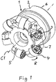
- a face milling tool 1 according to an embodiment of the invention is shown in Fig. 1 .
- the tool comprises a tool body 2 having six seats or pockets 3 each receiving a double-sided cutting insert 4 releasably fixed to the pocket.
- the cutting insert is removed from one of the pockets in Fig. 1 for illustrating the structure of the pockets.
- the tool body 2 includes a front end 5 and a rear end 6 between which a central rotation axis C1 extends around which the tool is rotatable in a direction of rotation R.
- the pockets 3 are formed in a transition between the front end and an envelope surface 7 extending between the front end and the rear end of the tool body.
- the double-sided inserts 4 are of the negative type, which are fixed in the pockets and tilted with an axial angle of -7° to -12° and a radial angle of -8° to -15° with respect to the central rotation axis C1 in order to provide clearance between the cutting inserts and workpiece.
- Other axial and radial angles are of course conceivable.
- Fig. 3 shows a cutting insert 4 according to an embodiment of the invention.
- the cutting insert is double-sided or reversible, which means that the top and bottom thereof have the same design, but the side shown with the orientation of the insert in the figure as the upper side will hereinafter be called the top, although it may just as well be the bottom or lower side of the insert.
- the insert has as seen in the figures a hidden lower surface 8, a top surface 9 and a surrounding side surface 10 connecting the lower surface and the top surface.
- the lower surface and the top surface are circular and have each a circular cutting edge 11, 12 formed between these surfaces and the side surface 10.
- the top surface 9 and the lower surface 8 are provided with a central recess 13 with a flat bottom surface 14.
- the recess 13 has six extended portions 15 of a valley- or finger-like design uniformly distributed around a centre axis C2 of the insert. These extended portions 15 are defined by border walls 16 of the recess and extend further radially with respect to said centre axis C2 than adjacent portions 17 of the recess.
- the insert is provided with a central axial through-hole 18 for securing it in a pocket 3 of the tool by a screw 19.
- Each pocket 3 has a portion 20 raised with respect to surrounding pocket portions 21 and provided with a flat support face 22 as upper surface.
- the raised portion 20 is configured to be received in the central recess 13 of the insert fixed in the pocket and provide support through the support face 22 to the bottom surface 14 of the recess.
- the pocket has also means configured to provide support to portions of the side surface 10 of an insert received in the pocket in the form of two separate support surfaces, one 23 for providing axial support and one 24 for providing radial support.
- These two support surfaces are formed by ridges with grooves therebetween, in which the grooves are manufactured by means of a ball nose end mill imparting a concavely arched shape thereto with the grooves having a depth being 0.015 to 0.025 mm.
- the raised portion 20 of the pocket has a first projecting member 25 configured to project into and be received in one extended recess portion 15 of the insert and engage portions 26 of recess border walls to establish mutual engagement of the insert and pocket to prevent rotation of the insert about the centre axis C2 of the insert by receiving a rotational moment acting on the insert in an active chip-removing state of the tool.
- the projecting member 25 carries said support face 22 to support the insert on the bottom surface 14 within a said extended recess portion 15.
- the first projecting member 25 is here directed at "six o'clock" with respect to the central rotation axis C1 of the tool which means in the direction of that axis, which means that it will provide support by the support face portion 27 thereon in the region of the insert configured to be exerted to a maximum load in an active chip-removing state of the tool and by that efficiently counteract any cracking or breaking tendency of the insert.
- the extended recess portions 15 are designed to allow said first projecting member to be designed to extend to a distance from said centre axis C2 of an insert received in the pocket being in the order of 90% of the distance from said centre axis to the side surface of the insert.
- the raised portion 20 is provided with two said projecting members and a second said projecting member 28 is configured to project into the extended recess portion 15 following upon the extended recess portion into which the first projecting member 25 is projecting as seen in the direction of a said rotational moment.
- the two projecting members are designed to project into a said extended recess portion with a clearance between delimiting walls 29 of the projecting member and the recess border walls 26 in the respective extended recess portion of the insert for simplifying mounting of the insert and avoiding that the seat of the pocket will be over-determined.
- the raised portion 20 of the pocket has a threaded bore 30 for receiving a screw 19 configured to secure the insert in the pocket.
- the bore 30 is located slightly offset with respect to the through-hole 18 of the insert, which means that the screw 19 will urge portions of the side surface 10 of the insert to bear under pretension against the support surfaces 23 and 24 of the pocket when the screw is tightened and then also press the bottom surface 14 of the central recess 13 of the insert against the support face 22 of the pocket.
- the insert may be indexed six times for having said first projecting member 25 received in each of the extended recess portions 15 and then reversed enabling 12 indexations of the insert.
- each central recess of the insert may be another than six.
- the insert may have a polygonal cross-section with a plurality of distinctive straight cutting edges along the upper and lower border thereof.
- the fastening means for securing the insert in the pocket may for instance be a clamp instead of a screw and the insert does then not need to have a central through-hole neither does the raised portion of the pocket then have to have a bore.
- the insert may be single-sided. Although the extended recess portions of the lower and the top surface are aligned with each other in the embodiment shown in the figures they may be displaced with respect to each other by any desired angle.
Description
- The present invention relates to a cutting tool configured for chip-removing machining according to the preamble of
claim 1. - Such a cutting tool is known from
US 2011/103905 A1 . - The invention is especially directed to cutting tools and indexable cutting inserts to be used in such tools for milling and will for that sake hereinafter mainly be discussed and illustrated for that particular application but is not at all restricted thereto. Said tool and insert may just as well be used for other types of chip-removing machining, such as turning. Examples of conceivable milling procedures are face milling, ramping and interpolation.
- Such milling tools have normally a plurality of, for example six, pockets to which a cutting insert is releasably fixed for enabling indexing of the cutting insert for changing the portion of the cutting edge thereof used for chip-removing machining. It is of vital importance for the result of said machining and the lifetime of said cutting insert that the insert received in said pocket or seat of the tool body is properly supported in a fixed position therein. Such support is to be provided by said means providing support to portions of the side surface of the insert and said flat support face providing support to the lower surface of the insert and against which fastening means is pressing the lower surface while securing the insert in a said pocket. It is also important that the insert may not move when a rotational moment is acting thereupon in an active chip-removing state of the tool, and that is ensured by an engagement member of the insert interacting with an engagement member of the pocket.
-
EP 2 764 939 A1 - The object of the present invention is to provide a cutting tool and a cutting insert of the type defined in the introduction being improved in at least some aspect with respect to such cutting tools and cutting inserts already known.
- This object is obtained by providing a cutting tool with the features of appended
claim 1. Preferred embodiments of the present invention are defined in the appended dependent claims. - By providing said support face through a raised portion proper support may be obtained by using the bottom surface of the recess provided for indexation and for preventing rotation of the insert received in the pocket. This does not only mean that an adequate support may be provided to said insert from below, but also a possibility to use a reversible, i.e. double-sided, insert in said cutting tool, which is not possible in a cutting tool having said support face as in the known cutting tool mentioned above. According to an embodiment of the invention said at least one projecting member carries said support face to support the insert on said bottom surface within said extended recess portion. This means that said support face will come close to the outer border of a recess receiving said projecting member improving the protection and support of portions of the insert exerted to cutting forces in the active chip-removing state of the tool.
- According to another embodiment of the invention said second engagement member comprises a first said projecting member located to support said insert through the support face portion thereon in the region configured to be exerted to load in an active chip-removing state of the tool. In a further development of that embodiment said first projecting member is projecting in a direction, as seen from said centre axis of an insert receiving this member, deviating by 0-45° from a corresponding direction pointing towards a point of said cutting edge exerted to a maximum load in an active chip-removing state of the tool. The insert will by this receive support through said support face where the cutting forces are the highest reducing any risk of cracking of said insert during said cutting operation.
- According to another embodiment of the invention said first projecting member, when received in a said extended recess portion, is configured to extend to a distance from said centre axis being at least 70%, 75%-95% or 80%-90% of the distance from said centre axis to said side surface of the insert. The support face will by that provide support to the insert close to the periphery of the insert reducing the risks of cracking of the insert where the risk thereof is normally the highest during said cutting operation.
- According to the invention said insert is provided with at least three said extended recess portions, and said second engagement member comprises two said projecting members. The arrangement of two said projecting members improves the stability and support of the insert in said pocket with respect to the presence of one said projecting member. It is then preferred that a second of said two projecting members is configured to project into the extended recess portion following upon the extended recess portion into which said first projecting member is projecting as seen in the direction of a said rotational moment acting on the insert in an active chip-removing state of the tool.
- According to the invention each said projecting member is designed to project into a said extended recess portion with a clearance between said delimiting walls of the projecting member and the recess border walls in said extended recess portion of the recess. The clearance may be very small, yet of such size that the insert's recess is easily mounted or placed onto the projecting member of the raised portion. The projecting member and the recess border wall may nevertheless be pressed against each other by the fastening means being arranged to press them together in the secured position of the insert. This furthermore means that said two projecting members may be formed on said raised portion without making the insert seat formed in the pocket over-determined. The second projecting member is provided with a larger clearance than the first projecting member to further facilitate the mounting of the insert's recess onto the support face and the projecting members.
- According to another embodiment of the invention said recess is provided with a plurality of valley- or finger-like said extended recess portions uniformly distributed around said centre axis of the insert, and the number of said portions may according to another embodiment of the invention be 2-8, 5-8, 6-8 or 6 resulting in a corresponding number of index positions of the insert when using said cutting edge for chip-removing machining.
- According to another embodiment of the invention said top surface of the insert is circular and said cutting edge is circular.
- According to another embodiment of the invention said insert is reversible in the sense that said lower and top surfaces thereof are identical and a said cutting edge is formed between each of these surfaces and said side surface of the insert, which results in a doubling of the number of possible indexations, which prolongs the service life of the cutting insert and thus provides for better tool economy with respect to for instance a cutting tool according to the document mentioned above.
- According to another embodiment of the invention said means providing support to portions of said side surface of the insert comprises at least one support surface comprising at least three ridges with grooves therebetween, the grooves being manufactured by means of a ball nose end mill imparting a concavely arched shape thereto, and the grooves have a depth being 0.015 to 0.025 mm. Such support surfaces and the production thereof are disclosed in
EP 1 629 917 B1 - According to another embodiment of the invention the cutting tool is a milling tool with said tool body including a front end and a rear end between which a central rotation axis extends around which the tool is rotatable in a direction of rotation, and said pocket is formed in a transition between the front end and an envelope surface extending between the front end and the rear end of the tool body. The cutting tool according to the present invention is particularly suitable for milling operations, especially face milling and ramping.
- According to another embodiment of the invention constituting a further development of the embodiment last mentioned said means configured to provide support to portions of said side surface of the insert comprises two separate support surfaces providing axial and radial support, respectively, to said insert with respect to said central rotation axis of the tool. These two separate support surfaces will together with said support face ensure that a cutting insert will receive accurate support and be held firmly in a said pocket in a milling tool according to the invention. It is then advantageous, as stated in another embodiment of the invention, to have said first projecting member projecting in a direction deviating by 0°-45°, 0°-25° or 0°-5° with respect to the extension of said central rotation axis of the tool. This means that said support face will provide proper support in the region of the insert where the cutting forces are the highest. In other words the support face is extended outwards to provide support to the lower surface of the insert in a region below and along the active cutting edge during milling.
- Other advantageous features as well as advantages of the present invention appear from the description following below.
- With reference to the appended drawings, below follows a specific description of an embodiment of the invention cited as an example.
- In the drawings:
- Fig. 1
- shows a perspective view of a milling tool according to the present invention,
- Fig. 2
- shows a perspective view of a pocket of the tool shown in
Fig. 1 , - Fig. 3
- shows a perspective view of a cutting insert according to an embodiment of the invention, and
- Fig. 4
- shows in transparency the cutting insert according to
Fig. 3 received in a pocket according toFig. 2 . - A
face milling tool 1 according to an embodiment of the invention is shown inFig. 1 . The tool comprises atool body 2 having six seats orpockets 3 each receiving a double-sidedcutting insert 4 releasably fixed to the pocket. The cutting insert is removed from one of the pockets inFig. 1 for illustrating the structure of the pockets. Thetool body 2 includes afront end 5 and a rear end 6 between which a central rotation axis C1 extends around which the tool is rotatable in a direction of rotation R. Thepockets 3 are formed in a transition between the front end and an envelope surface 7 extending between the front end and the rear end of the tool body. The double-sided inserts 4 are of the negative type, which are fixed in the pockets and tilted with an axial angle of -7° to -12° and a radial angle of -8° to -15° with respect to the central rotation axis C1 in order to provide clearance between the cutting inserts and workpiece. Other axial and radial angles are of course conceivable. - The construction of the milling tool shown in
Fig. 1 and the cutting inserts thereof will now be explained by making reference toFig. 1-4 .Fig. 3 shows a cuttinginsert 4 according to an embodiment of the invention. The cutting insert is double-sided or reversible, which means that the top and bottom thereof have the same design, but the side shown with the orientation of the insert in the figure as the upper side will hereinafter be called the top, although it may just as well be the bottom or lower side of the insert. Accordingly, the insert has as seen in the figures a hiddenlower surface 8, a top surface 9 and a surrounding side surface 10 connecting the lower surface and the top surface. The lower surface and the top surface are circular and have each acircular cutting edge lower surface 8 are provided with acentral recess 13 with aflat bottom surface 14. Therecess 13 has six extendedportions 15 of a valley- or finger-like design uniformly distributed around a centre axis C2 of the insert. Theseextended portions 15 are defined byborder walls 16 of the recess and extend further radially with respect to said centre axis C2 thanadjacent portions 17 of the recess. The insert is provided with a central axial through-hole 18 for securing it in apocket 3 of the tool by ascrew 19. Eachpocket 3 has aportion 20 raised with respect to surrounding pocket portions 21 and provided with aflat support face 22 as upper surface. The raisedportion 20 is configured to be received in thecentral recess 13 of the insert fixed in the pocket and provide support through thesupport face 22 to thebottom surface 14 of the recess. - The pocket has also means configured to provide support to portions of the side surface 10 of an insert received in the pocket in the form of two separate support surfaces, one 23 for providing axial support and one 24 for providing radial support. These two support surfaces are formed by ridges with grooves therebetween, in which the grooves are manufactured by means of a ball nose end mill imparting a concavely arched shape thereto with the grooves having a depth being 0.015 to 0.025 mm.
- The raised
portion 20 of the pocket has a first projectingmember 25 configured to project into and be received in oneextended recess portion 15 of the insert and engageportions 26 of recess border walls to establish mutual engagement of the insert and pocket to prevent rotation of the insert about the centre axis C2 of the insert by receiving a rotational moment acting on the insert in an active chip-removing state of the tool. The projectingmember 25 carries saidsupport face 22 to support the insert on thebottom surface 14 within a saidextended recess portion 15. The first projectingmember 25 is here directed at "six o'clock" with respect to the central rotation axis C1 of the tool which means in the direction of that axis, which means that it will provide support by thesupport face portion 27 thereon in the region of the insert configured to be exerted to a maximum load in an active chip-removing state of the tool and by that efficiently counteract any cracking or breaking tendency of the insert. Theextended recess portions 15 are designed to allow said first projecting member to be designed to extend to a distance from said centre axis C2 of an insert received in the pocket being in the order of 90% of the distance from said centre axis to the side surface of the insert. The raisedportion 20 is provided with two said projecting members and a second said projectingmember 28 is configured to project into theextended recess portion 15 following upon the extended recess portion into which the first projectingmember 25 is projecting as seen in the direction of a said rotational moment. The two projecting members are designed to project into a said extended recess portion with a clearance between delimiting walls 29 of the projecting member and therecess border walls 26 in the respective extended recess portion of the insert for simplifying mounting of the insert and avoiding that the seat of the pocket will be over-determined. - The raised
portion 20 of the pocket has a threadedbore 30 for receiving ascrew 19 configured to secure the insert in the pocket. Thebore 30 is located slightly offset with respect to the through-hole 18 of the insert, which means that thescrew 19 will urge portions of the side surface 10 of the insert to bear under pretension against the support surfaces 23 and 24 of the pocket when the screw is tightened and then also press thebottom surface 14 of thecentral recess 13 of the insert against thesupport face 22 of the pocket. When the operation of the tool is started a rotational moment about the central rotation axis C2 will be applied to each insert trying to rotate the insert and ensuring stable and reproducible positioning of the insert in the pocket by bringing delimiting walls 29 of the first projectingmember 25 into engagement withportions 26 of the recess border wall of the insert preventing further rotation of the insert. - The insert may be indexed six times for having said first projecting
member 25 received in each of theextended recess portions 15 and then reversed enabling 12 indexations of the insert. - The number of indexations provided by each central recess of the insert may be another than six. The insert may have a polygonal cross-section with a plurality of distinctive straight cutting edges along the upper and lower border thereof. The fastening means for securing the insert in the pocket may for instance be a clamp instead of a screw and the insert does then not need to have a central through-hole neither does the raised portion of the pocket then have to have a bore. The insert may be single-sided. Although the extended recess portions of the lower and the top surface are aligned with each other in the embodiment shown in the figures they may be displaced with respect to each other by any desired angle.
Claims (14)
- A cutting tool, comprising:• a tool body (2) having at least one pocket (3),• at least one cutting insert (4) releasably fixed to said pocket, said insert having a lower surface (8), a top surface (9), a surrounding side surface (10) connecting the lower surface and the top surface and at least one cutting edge (11, 12) formed between the top surface and the side surface,
said pocket having means (23, 24) configured to provide support to portions of said side surface and a flat support face (22) configured to provide support to at least portions (14) of said lower surface of said insert, and• fastening means (19) configured to secure said insert (4) in said pocket (3) while pressing said portions (14) of said lower surface against said support face (22),said insert having a first engagement member (15) and said pocket a second engagement member (25, 28) configured to establish mutual engagement of the insert and pocket to prevent rotation of the insert about an insert centre axis (C2) extending through said top surface and lower surface of the insert by receiving a rotational moment acting on the insert in an active chip-removing state of the tool,said lower surface of the insert having a central recess (13) with a flat bottom surface (14), said first engagement member comprising at least two extended portions (15) of said recess defined by border walls (16) of said recess and extending further radially with respect to said centre axis than adjacent portions (17) of said recess and said second engagement member comprising at least one fixed projecting member (25, 28) of the pocket (3) configured to project into and be received alternatively in one of said extended recess portions (15) and engage portions of said recess border walls (16) to establish said mutual engagement and enabling indexing of said insert, said pocket of the tool body having a portion (20) raised with respect to surrounding pocket portions (21) and having said support face (22) as upper surface,said raised portion being designed to be received in said recess (13) of the insert (4) and support the insert by receiving said bottom surface (14) of the recess (13) bearing on said support face (22),said at least one projecting member (25, 28) of the second engagement member being formed by said raised portion (20) having delimiting walls (29) designed to bear against said recess border walls (16) of said extended recess portion so as to establish said mutual engagement to prevent rotation,said insert (4) being provided with at least three said extended recess portions (15), and said second engagement member comprising two said projecting members (25, 28),characterized in that each said projecting member (25, 28) is designed to project into a said extended recess portion (15) with a clearance between said delimiting walls (29) of the projecting member and the recess border walls (26) in said extended recess portion of the insert and that a second projecting member of said two fixed projecting members (25, 28) is provided with a larger clearance than a first projecting member of said two fixed projecting members (25, 28). - The cutting tool according to claim 1, characterized in that said at least one projecting member (25, 28) carries said support face (22) to support the insert on said bottom surface (14) within a said extended recess portion (15).
- The cutting tool according to claim 2, characterized in that said second engagement member comprises a first said projecting member (25) located to support a said insert through the support face portion (27) thereon in the region configured to be exerted to load in an active chip-removing state of the tool.
- The cutting tool according to claim 3, characterized in that said first projecting member (25) is projecting in a direction, as seen from said centre axis (C2) of an insert receiving this member, deviating by 0-45° from a corresponding direction pointing towards a point of said cutting edge (11, 12) exerted to a maximum load in an active chip-removing state of the tool.
- The cutting tool according to any of claims 2-4, characterized in that said first projecting member (25), when received in a said extended recess portion (15), is configured to extend to a distance from said centre axis (C2) being at least 70%, 75%-95% or 80%-90% of the distance from said centre axis to said side surface (10) of the insert.
- The cutting tool according to claim 1, depending upon any of claims 3-5, characterized in that a second (28) of said two projecting members is configured to project into the extended recess portion (15) following upon the extended recess portion into which said first projecting member (25) is projecting as seen in the direction of a said rotational moment acting on the insert in an active chip-removing state of the tool.
- The cutting tool according to any of the preceding claims, characterized in that said recess (13) is provided with a plurality of valley- or finger-like said extended recess portions (15) uniformly distributed around said centre axis (C2) of the insert.
- The cutting tool according to claim 7, characterized in that said insert has5-8, 6-8 or 6 said extended recess portions (15) in said central recess (13).
- The cutting tool according to any of the preceding claims, characterized in that said top surface (9) of the insert is circular and said cutting edge (12) is circular.
- The cutting tool according to any of the preceding claims, characterized in that said insert (4) is reversible in the sense that said lower (8) and top (9) surfaces thereof are identical and a said cutting edge (11, 12) is formed between each of these surfaces and said side surface (10) of the insert.
- The cutting tool according to any of the preceding claims, characterized in that said means providing support to portions of said side surface (10) of the insert comprises at least one support surface (23, 24) comprising at least three ridges with grooves therebetween, the grooves being manufactured by means of a ball nose end mill imparting a concavely arched shape thereto, and that the grooves have a depth being 0.015 to 0.025 mm.
- The cutting tool according to any of the preceding claims, characterized in that it is a milling tool with said tool body (2) including a front end (5) and a rear end (6) between which a central rotation axis (C1) extends around which the tool is rotatable in a direction of rotation, and that said pocket (3) is formed in a transition between the front end (5) and an envelope surface (7) extending between the front end and the rear end of the tool body.
- The cutting tool according to claim 12, characterized in that said means configured to provide support to portions of said side surface (10) of the insert comprises two separate support surfaces (23, 24) providing axial and radial support, respectively, to said insert with respect to said central rotation axis (C1) of the tool.
- The cutting tool according to claim 3 and 12 or 13, characterized in that said first projecting member (25) projects in a direction deviating by 0°-45°, 0°-25° or 0°-5° with respect to the extension of said central rotation axis (C1) of the tool.
Priority Applications (8)
| Application Number | Priority Date | Filing Date | Title |
|---|---|---|---|
| EP14186207.8A EP3000549B1 (en) | 2014-09-24 | 2014-09-24 | A cutting tool and a cutting insert for a chip-removing tool |
| CN202211242988.3A CN115502456A (en) | 2014-09-24 | 2015-09-03 | Cutting tool and cutting insert for a chip removing tool |
| US15/513,591 US10252355B2 (en) | 2014-09-24 | 2015-09-03 | Cutting tool and a cutting insert for chip-removing tool |
| KR1020177007511A KR102362021B1 (en) | 2014-09-24 | 2015-09-03 | A cutting tool and a cutting insert for a chip-removing tool |
| JP2017516456A JP6762294B2 (en) | 2014-09-24 | 2015-09-03 | Cutting inserts for cutting tools and chip removal tools |
| CN201580047212.8A CN106660148A (en) | 2014-09-24 | 2015-09-03 | A cutting tool and a cutting insert for a chip-removing tool |
| BR112017006055A BR112017006055A2 (en) | 2014-09-24 | 2015-09-03 | a cutting tool and a cutting insert for a chip removal tool |
| PCT/EP2015/070131 WO2016045928A1 (en) | 2014-09-24 | 2015-09-03 | A cutting tool and a cutting insert for a chip-removing tool |
Applications Claiming Priority (1)
| Application Number | Priority Date | Filing Date | Title |
|---|---|---|---|
| EP14186207.8A EP3000549B1 (en) | 2014-09-24 | 2014-09-24 | A cutting tool and a cutting insert for a chip-removing tool |
Publications (2)
| Publication Number | Publication Date |
|---|---|
| EP3000549A1 EP3000549A1 (en) | 2016-03-30 |
| EP3000549B1 true EP3000549B1 (en) | 2022-11-09 |
Family
ID=51585043
Family Applications (1)
| Application Number | Title | Priority Date | Filing Date |
|---|---|---|---|
| EP14186207.8A Active EP3000549B1 (en) | 2014-09-24 | 2014-09-24 | A cutting tool and a cutting insert for a chip-removing tool |
Country Status (7)
| Country | Link |
|---|---|
| US (1) | US10252355B2 (en) |
| EP (1) | EP3000549B1 (en) |
| JP (1) | JP6762294B2 (en) |
| KR (1) | KR102362021B1 (en) |
| CN (2) | CN115502456A (en) |
| BR (1) | BR112017006055A2 (en) |
| WO (1) | WO2016045928A1 (en) |
Families Citing this family (6)
| Publication number | Priority date | Publication date | Assignee | Title |
|---|---|---|---|---|
| EP3351329B1 (en) * | 2017-01-18 | 2023-08-02 | Sandvik Intellectual Property AB | Indexable cutting insert for a milling tool |
| US10646927B2 (en) * | 2018-02-19 | 2020-05-12 | Iscar, Ltd. | Round double-sided cutting insert having a peripheral surface provided with protruding indexing latches, insert holder therefor and cutting tool |
| EP3560644B1 (en) * | 2018-04-27 | 2022-10-05 | Seco Tools Ab | A tool body and a milling tool |
| JP7012948B1 (en) * | 2021-03-10 | 2022-01-31 | 株式会社タンガロイ | Tool body of replaceable cutting tool |
| US11786982B2 (en) | 2021-04-26 | 2023-10-17 | Kennametal Inc. | Cutting tool comprising toolholder and round cutting insert and method for repositioning the round cutting insert in a pocket of the toolholder |
| CN113275635B (en) * | 2021-05-21 | 2022-10-11 | 株洲华锐精密工具股份有限公司 | Cutting tool |
Citations (1)
| Publication number | Priority date | Publication date | Assignee | Title |
|---|---|---|---|---|
| JP2013075337A (en) * | 2011-09-30 | 2013-04-25 | Hitachi Tool Engineering Ltd | Cutting edge exchange type cutting tool |
Family Cites Families (20)
| Publication number | Priority date | Publication date | Assignee | Title |
|---|---|---|---|---|
| SE505511C2 (en) * | 1994-12-15 | 1997-09-08 | Sandvik Ab | Milling body and method of manufacture thereof |
| SE516501C2 (en) * | 2000-05-18 | 2002-01-22 | Sandvik Ab | Utilities Connection |
| SE525913C2 (en) * | 2002-12-20 | 2005-05-24 | Seco Tools Ab | Cutter, tool and method of mounting the insert where the insert can be oriented in the desired position |
| SE527543C2 (en) | 2004-08-30 | 2006-04-04 | Sandvik Intellectual Property | Cutting position with grooved support surface |
| SE530181C2 (en) * | 2005-12-21 | 2008-03-18 | Sandvik Intellectual Property | Tools for chip separating machining and basic body and separate locking means for this |
| IL182343A0 (en) * | 2007-04-01 | 2007-07-24 | Iscar Ltd | Cutting insert and tool for milling and ramping at high feed rates |
| SE531502C2 (en) * | 2007-06-05 | 2009-04-28 | Sandvik Intellectual Property | Tools for chip separating machining as well as basic body and indexable cutting for this |
| KR101549718B1 (en) * | 2008-06-26 | 2015-09-02 | 쎄코 툴스 에이비 | Family of cutting inserts, milling cutting tool, and cutting insert background and summary |
| US8573903B2 (en) * | 2009-11-03 | 2013-11-05 | Kennametal Inc. | Round cutting insert with anti-rotation feature |
| US8657539B2 (en) * | 2011-03-28 | 2014-02-25 | Kennametal Inc. | Round cutting insert with reverse anti-rotation feature |
| WO2013051703A1 (en) * | 2011-10-07 | 2013-04-11 | 株式会社タンガロイ | Cutting tool with replaceable blade edge |
| SE536345C2 (en) * | 2012-01-20 | 2013-09-03 | Sandvik Intellectual Property | Hole cutting tools with interchangeable cutting tools including male and female securing means |
| SE536344C2 (en) * | 2012-01-30 | 2013-09-03 | Sandvik Intellectual Property | Milling tools and milling cutters where the cutting edge has an acute pitch |
| US8858130B2 (en) * | 2012-04-24 | 2014-10-14 | Kennametal Inc. | Indexable circular cutting insert |
| US20130330136A1 (en) * | 2012-06-06 | 2013-12-12 | Iscar, Ltd. | Cutting Insert and Tool Having an Anti-Slip Arrangement |
| US9011049B2 (en) * | 2012-09-25 | 2015-04-21 | Kennametal Inc. | Double-sided cutting inserts with anti-rotation features |
| US9283626B2 (en) * | 2012-09-25 | 2016-03-15 | Kennametal Inc. | Double-sided cutting inserts with anti-rotation features |
| JP6524590B2 (en) * | 2014-06-24 | 2019-06-05 | 住友電工ハードメタル株式会社 | Cutting tool and tool body |
| US10406608B2 (en) * | 2015-01-19 | 2019-09-10 | Kennametal Inc. | Cutting insert and pocket with uninterrupted and continuous seating surface perimeter |
| JP6020949B1 (en) * | 2015-02-19 | 2016-11-02 | 株式会社タンガロイ | Tool bodies and cutting tools |
-
2014
- 2014-09-24 EP EP14186207.8A patent/EP3000549B1/en active Active
-
2015
- 2015-09-03 CN CN202211242988.3A patent/CN115502456A/en active Pending
- 2015-09-03 WO PCT/EP2015/070131 patent/WO2016045928A1/en active Application Filing
- 2015-09-03 BR BR112017006055A patent/BR112017006055A2/en not_active Application Discontinuation
- 2015-09-03 KR KR1020177007511A patent/KR102362021B1/en active IP Right Grant
- 2015-09-03 CN CN201580047212.8A patent/CN106660148A/en active Pending
- 2015-09-03 US US15/513,591 patent/US10252355B2/en active Active
- 2015-09-03 JP JP2017516456A patent/JP6762294B2/en active Active
Patent Citations (1)
| Publication number | Priority date | Publication date | Assignee | Title |
|---|---|---|---|---|
| JP2013075337A (en) * | 2011-09-30 | 2013-04-25 | Hitachi Tool Engineering Ltd | Cutting edge exchange type cutting tool |
Also Published As
| Publication number | Publication date |
|---|---|
| US10252355B2 (en) | 2019-04-09 |
| KR102362021B1 (en) | 2022-02-10 |
| KR20170058373A (en) | 2017-05-26 |
| US20170291233A1 (en) | 2017-10-12 |
| BR112017006055A2 (en) | 2017-12-19 |
| CN106660148A (en) | 2017-05-10 |
| JP2017528330A (en) | 2017-09-28 |
| JP6762294B2 (en) | 2020-09-30 |
| WO2016045928A1 (en) | 2016-03-31 |
| CN115502456A (en) | 2022-12-23 |
| EP3000549A1 (en) | 2016-03-30 |
Similar Documents
| Publication | Publication Date | Title |
|---|---|---|
| EP3000549B1 (en) | A cutting tool and a cutting insert for a chip-removing tool | |
| CN102029422B (en) | A shim plate for milling tools for chip removing machining as well as a milling tool having such a shim plate | |
| EP3199284B1 (en) | An indexable cutting insert for an end mill tool and an end mill tool provided with such an insert | |
| US9776258B2 (en) | Double-sided, trigon cutting insert with rounded minor cutting edge and cutting tool therefor | |
| CN110497006B (en) | Cutting insert and cutting tool | |
| US20160207124A1 (en) | Cutting insert and pocket with uninterrupted and continuous seating surface perimeter | |
| KR102379492B1 (en) | Cutting inserts and shoulder milling tools | |
| US20190160563A1 (en) | Single-sided four-way indexable positive cutting insert and insert mill therefor | |
| KR20170086513A (en) | A cutting insert and a cutting tool for milling square shoulders | |
| EP3924128A1 (en) | Rotary cutting body having insert pocket with seat surface provided with a plurality of abutment elements, rotary cutting tool and insert | |
| US7357603B2 (en) | Toolholder and cutting insert used therein | |
| EP2730360A1 (en) | Cutting insert and cutting tool | |
| CN110114177B (en) | Indexable cutting insert for milling tools | |
| US8540462B2 (en) | Shim plate for tools for cutting machining as well as a tool | |
| US10906107B2 (en) | Single-sided four-way indexable positive cutting insert and insert mill therefor | |
| JP7335239B2 (en) | Single-sided four-way indexable positive cutting inserts and insert mills therefor |
Legal Events
| Date | Code | Title | Description |
|---|---|---|---|
| PUAI | Public reference made under article 153(3) epc to a published international application that has entered the european phase |
Free format text: ORIGINAL CODE: 0009012 |
|
| AK | Designated contracting states |
Kind code of ref document: A1 Designated state(s): AL AT BE BG CH CY CZ DE DK EE ES FI FR GB GR HR HU IE IS IT LI LT LU LV MC MK MT NL NO PL PT RO RS SE SI SK SM TR |
|
| AX | Request for extension of the european patent |
Extension state: BA ME |
|
| 17P | Request for examination filed |
Effective date: 20160930 |
|
| RBV | Designated contracting states (corrected) |
Designated state(s): AL AT BE BG CH CY CZ DE DK EE ES FI FR GB GR HR HU IE IS IT LI LT LU LV MC MK MT NL NO PL PT RO RS SE SI SK SM TR |
|
| STAA | Information on the status of an ep patent application or granted ep patent |
Free format text: STATUS: EXAMINATION IS IN PROGRESS |
|
| 17Q | First examination report despatched |
Effective date: 20190605 |
|
| STAA | Information on the status of an ep patent application or granted ep patent |
Free format text: STATUS: EXAMINATION IS IN PROGRESS |
|
| GRAP | Despatch of communication of intention to grant a patent |
Free format text: ORIGINAL CODE: EPIDOSNIGR1 |
|
| STAA | Information on the status of an ep patent application or granted ep patent |
Free format text: STATUS: GRANT OF PATENT IS INTENDED |
|
| INTG | Intention to grant announced |
Effective date: 20220504 |
|
| RIN1 | Information on inventor provided before grant (corrected) |
Inventor name: MARIE, GILLES Inventor name: RUE, MARC Inventor name: GASTHUYS, JACQUES |
|
| GRAS | Grant fee paid |
Free format text: ORIGINAL CODE: EPIDOSNIGR3 |
|
| GRAA | (expected) grant |
Free format text: ORIGINAL CODE: 0009210 |
|
| STAA | Information on the status of an ep patent application or granted ep patent |
Free format text: STATUS: THE PATENT HAS BEEN GRANTED |
|
| AK | Designated contracting states |
Kind code of ref document: B1 Designated state(s): AL AT BE BG CH CY CZ DE DK EE ES FI FR GB GR HR HU IE IS IT LI LT LU LV MC MK MT NL NO PL PT RO RS SE SI SK SM TR |
|
| REG | Reference to a national code |
Ref country code: GB Ref legal event code: FG4D |
|
| REG | Reference to a national code |
Ref country code: CH Ref legal event code: EP Ref country code: AT Ref legal event code: REF Ref document number: 1530033 Country of ref document: AT Kind code of ref document: T Effective date: 20221115 |
|
| REG | Reference to a national code |
Ref country code: DE Ref legal event code: R096 Ref document number: 602014085465 Country of ref document: DE |
|
| REG | Reference to a national code |
Ref country code: IE Ref legal event code: FG4D |
|
| REG | Reference to a national code |
Ref country code: LT Ref legal event code: MG9D |
|
| REG | Reference to a national code |
Ref country code: NL Ref legal event code: MP Effective date: 20221109 |
|
| REG | Reference to a national code |
Ref country code: AT Ref legal event code: MK05 Ref document number: 1530033 Country of ref document: AT Kind code of ref document: T Effective date: 20221109 |
|
| PG25 | Lapsed in a contracting state [announced via postgrant information from national office to epo] |
Ref country code: SE Free format text: LAPSE BECAUSE OF FAILURE TO SUBMIT A TRANSLATION OF THE DESCRIPTION OR TO PAY THE FEE WITHIN THE PRESCRIBED TIME-LIMIT Effective date: 20221109 Ref country code: PT Free format text: LAPSE BECAUSE OF FAILURE TO SUBMIT A TRANSLATION OF THE DESCRIPTION OR TO PAY THE FEE WITHIN THE PRESCRIBED TIME-LIMIT Effective date: 20230309 Ref country code: NO Free format text: LAPSE BECAUSE OF FAILURE TO SUBMIT A TRANSLATION OF THE DESCRIPTION OR TO PAY THE FEE WITHIN THE PRESCRIBED TIME-LIMIT Effective date: 20230209 Ref country code: LT Free format text: LAPSE BECAUSE OF FAILURE TO SUBMIT A TRANSLATION OF THE DESCRIPTION OR TO PAY THE FEE WITHIN THE PRESCRIBED TIME-LIMIT Effective date: 20221109 Ref country code: FI Free format text: LAPSE BECAUSE OF FAILURE TO SUBMIT A TRANSLATION OF THE DESCRIPTION OR TO PAY THE FEE WITHIN THE PRESCRIBED TIME-LIMIT Effective date: 20221109 Ref country code: ES Free format text: LAPSE BECAUSE OF FAILURE TO SUBMIT A TRANSLATION OF THE DESCRIPTION OR TO PAY THE FEE WITHIN THE PRESCRIBED TIME-LIMIT Effective date: 20221109 Ref country code: AT Free format text: LAPSE BECAUSE OF FAILURE TO SUBMIT A TRANSLATION OF THE DESCRIPTION OR TO PAY THE FEE WITHIN THE PRESCRIBED TIME-LIMIT Effective date: 20221109 |
|
| PG25 | Lapsed in a contracting state [announced via postgrant information from national office to epo] |
Ref country code: RS Free format text: LAPSE BECAUSE OF FAILURE TO SUBMIT A TRANSLATION OF THE DESCRIPTION OR TO PAY THE FEE WITHIN THE PRESCRIBED TIME-LIMIT Effective date: 20221109 Ref country code: PL Free format text: LAPSE BECAUSE OF FAILURE TO SUBMIT A TRANSLATION OF THE DESCRIPTION OR TO PAY THE FEE WITHIN THE PRESCRIBED TIME-LIMIT Effective date: 20221109 Ref country code: LV Free format text: LAPSE BECAUSE OF FAILURE TO SUBMIT A TRANSLATION OF THE DESCRIPTION OR TO PAY THE FEE WITHIN THE PRESCRIBED TIME-LIMIT Effective date: 20221109 Ref country code: IS Free format text: LAPSE BECAUSE OF FAILURE TO SUBMIT A TRANSLATION OF THE DESCRIPTION OR TO PAY THE FEE WITHIN THE PRESCRIBED TIME-LIMIT Effective date: 20230309 Ref country code: HR Free format text: LAPSE BECAUSE OF FAILURE TO SUBMIT A TRANSLATION OF THE DESCRIPTION OR TO PAY THE FEE WITHIN THE PRESCRIBED TIME-LIMIT Effective date: 20221109 Ref country code: GR Free format text: LAPSE BECAUSE OF FAILURE TO SUBMIT A TRANSLATION OF THE DESCRIPTION OR TO PAY THE FEE WITHIN THE PRESCRIBED TIME-LIMIT Effective date: 20230210 |
|
| PG25 | Lapsed in a contracting state [announced via postgrant information from national office to epo] |
Ref country code: NL Free format text: LAPSE BECAUSE OF FAILURE TO SUBMIT A TRANSLATION OF THE DESCRIPTION OR TO PAY THE FEE WITHIN THE PRESCRIBED TIME-LIMIT Effective date: 20221109 |
|
| P01 | Opt-out of the competence of the unified patent court (upc) registered |
Effective date: 20230603 |
|
| PG25 | Lapsed in a contracting state [announced via postgrant information from national office to epo] |
Ref country code: SM Free format text: LAPSE BECAUSE OF FAILURE TO SUBMIT A TRANSLATION OF THE DESCRIPTION OR TO PAY THE FEE WITHIN THE PRESCRIBED TIME-LIMIT Effective date: 20221109 Ref country code: RO Free format text: LAPSE BECAUSE OF FAILURE TO SUBMIT A TRANSLATION OF THE DESCRIPTION OR TO PAY THE FEE WITHIN THE PRESCRIBED TIME-LIMIT Effective date: 20221109 Ref country code: EE Free format text: LAPSE BECAUSE OF FAILURE TO SUBMIT A TRANSLATION OF THE DESCRIPTION OR TO PAY THE FEE WITHIN THE PRESCRIBED TIME-LIMIT Effective date: 20221109 Ref country code: DK Free format text: LAPSE BECAUSE OF FAILURE TO SUBMIT A TRANSLATION OF THE DESCRIPTION OR TO PAY THE FEE WITHIN THE PRESCRIBED TIME-LIMIT Effective date: 20221109 Ref country code: CZ Free format text: LAPSE BECAUSE OF FAILURE TO SUBMIT A TRANSLATION OF THE DESCRIPTION OR TO PAY THE FEE WITHIN THE PRESCRIBED TIME-LIMIT Effective date: 20221109 |
|
| REG | Reference to a national code |
Ref country code: DE Ref legal event code: R097 Ref document number: 602014085465 Country of ref document: DE |
|
| PG25 | Lapsed in a contracting state [announced via postgrant information from national office to epo] |
Ref country code: SK Free format text: LAPSE BECAUSE OF FAILURE TO SUBMIT A TRANSLATION OF THE DESCRIPTION OR TO PAY THE FEE WITHIN THE PRESCRIBED TIME-LIMIT Effective date: 20221109 Ref country code: AL Free format text: LAPSE BECAUSE OF FAILURE TO SUBMIT A TRANSLATION OF THE DESCRIPTION OR TO PAY THE FEE WITHIN THE PRESCRIBED TIME-LIMIT Effective date: 20221109 |
|
| PLBE | No opposition filed within time limit |
Free format text: ORIGINAL CODE: 0009261 |
|
| STAA | Information on the status of an ep patent application or granted ep patent |
Free format text: STATUS: NO OPPOSITION FILED WITHIN TIME LIMIT |
|
| 26N | No opposition filed |
Effective date: 20230810 |
|
| PGFP | Annual fee paid to national office [announced via postgrant information from national office to epo] |
Ref country code: IT Payment date: 20230810 Year of fee payment: 10 Ref country code: GB Payment date: 20230803 Year of fee payment: 10 |
|
| PG25 | Lapsed in a contracting state [announced via postgrant information from national office to epo] |
Ref country code: SI Free format text: LAPSE BECAUSE OF FAILURE TO SUBMIT A TRANSLATION OF THE DESCRIPTION OR TO PAY THE FEE WITHIN THE PRESCRIBED TIME-LIMIT Effective date: 20221109 |
|
| PGFP | Annual fee paid to national office [announced via postgrant information from national office to epo] |
Ref country code: FR Payment date: 20230821 Year of fee payment: 10 Ref country code: DE Payment date: 20230802 Year of fee payment: 10 |