EP3000549B1 - Schneidwerkzeug und Schneideinsatz für ein spanabhebendes Werkzeug - Google Patents
Schneidwerkzeug und Schneideinsatz für ein spanabhebendes Werkzeug Download PDFInfo
- Publication number
- EP3000549B1 EP3000549B1 EP14186207.8A EP14186207A EP3000549B1 EP 3000549 B1 EP3000549 B1 EP 3000549B1 EP 14186207 A EP14186207 A EP 14186207A EP 3000549 B1 EP3000549 B1 EP 3000549B1
- Authority
- EP
- European Patent Office
- Prior art keywords
- insert
- recess
- support
- portions
- Prior art date
- Legal status (The legal status is an assumption and is not a legal conclusion. Google has not performed a legal analysis and makes no representation as to the accuracy of the status listed.)
- Active
Links
Images

Classifications
-
- B—PERFORMING OPERATIONS; TRANSPORTING
- B23—MACHINE TOOLS; METAL-WORKING NOT OTHERWISE PROVIDED FOR
- B23C—MILLING
- B23C5/00—Milling-cutters
- B23C5/16—Milling-cutters characterised by physical features other than shape
- B23C5/20—Milling-cutters characterised by physical features other than shape with removable cutter bits or teeth or cutting inserts
- B23C5/22—Securing arrangements for bits or teeth or cutting inserts
- B23C5/2204—Securing arrangements for bits or teeth or cutting inserts with cutting inserts clamped against the walls of the recess in the cutter body by a clamping member acting upon the wall of a hole in the insert
- B23C5/2208—Securing arrangements for bits or teeth or cutting inserts with cutting inserts clamped against the walls of the recess in the cutter body by a clamping member acting upon the wall of a hole in the insert for plate-like cutting inserts
- B23C5/2213—Securing arrangements for bits or teeth or cutting inserts with cutting inserts clamped against the walls of the recess in the cutter body by a clamping member acting upon the wall of a hole in the insert for plate-like cutting inserts having a special shape
-
- B—PERFORMING OPERATIONS; TRANSPORTING
- B23—MACHINE TOOLS; METAL-WORKING NOT OTHERWISE PROVIDED FOR
- B23C—MILLING
- B23C5/00—Milling-cutters
- B23C5/02—Milling-cutters characterised by the shape of the cutter
- B23C5/06—Face-milling cutters, i.e. having only or primarily a substantially flat cutting surface
-
- B—PERFORMING OPERATIONS; TRANSPORTING
- B23—MACHINE TOOLS; METAL-WORKING NOT OTHERWISE PROVIDED FOR
- B23C—MILLING
- B23C5/00—Milling-cutters
- B23C5/16—Milling-cutters characterised by physical features other than shape
- B23C5/20—Milling-cutters characterised by physical features other than shape with removable cutter bits or teeth or cutting inserts
- B23C5/22—Securing arrangements for bits or teeth or cutting inserts
- B23C5/2239—Securing arrangements for bits or teeth or cutting inserts with cutting inserts clamped by a clamping member acting almost perpendicular on the cutting face
- B23C5/2243—Securing arrangements for bits or teeth or cutting inserts with cutting inserts clamped by a clamping member acting almost perpendicular on the cutting face for plate-like cutting inserts
- B23C5/2247—Securing arrangements for bits or teeth or cutting inserts with cutting inserts clamped by a clamping member acting almost perpendicular on the cutting face for plate-like cutting inserts having a special shape
-
- B—PERFORMING OPERATIONS; TRANSPORTING
- B23—MACHINE TOOLS; METAL-WORKING NOT OTHERWISE PROVIDED FOR
- B23C—MILLING
- B23C2200/00—Details of milling cutting inserts
- B23C2200/04—Overall shape
- B23C2200/045—Round
-
- B—PERFORMING OPERATIONS; TRANSPORTING
- B23—MACHINE TOOLS; METAL-WORKING NOT OTHERWISE PROVIDED FOR
- B23C—MILLING
- B23C2200/00—Details of milling cutting inserts
- B23C2200/16—Supporting or bottom surfaces
- B23C2200/165—Supporting or bottom surfaces with one or more grooves
-
- B—PERFORMING OPERATIONS; TRANSPORTING
- B23—MACHINE TOOLS; METAL-WORKING NOT OTHERWISE PROVIDED FOR
- B23C—MILLING
- B23C2200/00—Details of milling cutting inserts
- B23C2200/16—Supporting or bottom surfaces
- B23C2200/168—Supporting or bottom surfaces with features related to indexing
-
- B—PERFORMING OPERATIONS; TRANSPORTING
- B23—MACHINE TOOLS; METAL-WORKING NOT OTHERWISE PROVIDED FOR
- B23C—MILLING
- B23C2210/00—Details of milling cutters
- B23C2210/16—Fixation of inserts or cutting bits in the tool
- B23C2210/163—Indexing
-
- B—PERFORMING OPERATIONS; TRANSPORTING
- B23—MACHINE TOOLS; METAL-WORKING NOT OTHERWISE PROVIDED FOR
- B23C—MILLING
- B23C2210/00—Details of milling cutters
- B23C2210/16—Fixation of inserts or cutting bits in the tool
- B23C2210/168—Seats for cutting inserts, supports for replacable cutting bits
Definitions
- the present invention relates to a cutting tool configured for chip-removing machining according to the preamble of claim 1.
- Such a cutting tool is known from US 2011/103905 A1 .
- the invention is especially directed to cutting tools and indexable cutting inserts to be used in such tools for milling and will for that sake hereinafter mainly be discussed and illustrated for that particular application but is not at all restricted thereto.
- Said tool and insert may just as well be used for other types of chip-removing machining, such as turning. Examples of conceivable milling procedures are face milling, ramping and interpolation.
- Such milling tools have normally a plurality of, for example six, pockets to which a cutting insert is releasably fixed for enabling indexing of the cutting insert for changing the portion of the cutting edge thereof used for chip-removing machining. It is of vital importance for the result of said machining and the lifetime of said cutting insert that the insert received in said pocket or seat of the tool body is properly supported in a fixed position therein.
- Such support is to be provided by said means providing support to portions of the side surface of the insert and said flat support face providing support to the lower surface of the insert and against which fastening means is pressing the lower surface while securing the insert in a said pocket. It is also important that the insert may not move when a rotational moment is acting thereupon in an active chip-removing state of the tool, and that is ensured by an engagement member of the insert interacting with an engagement member of the pocket.
- EP 2 764 939 A1 discloses a cutting tool and a cutting insert of the type defined in the introduction.
- the support face of the pocket is in that tool provided by a flat pocket bottom surface onto which the portions of said lower surface of the insert surrounding said central recess are applied for receiving support thereby.
- An engagement member is arranged on top of that support face so as to be received in said recess and forming a projecting member for obtaining engagement with a specific extended recess portion and prevent rotation of the insert in said active chip-removing state of the tool.
- the object of the present invention is to provide a cutting tool and a cutting insert of the type defined in the introduction being improved in at least some aspect with respect to such cutting tools and cutting inserts already known.
- said at least one projecting member carries said support face to support the insert on said bottom surface within said extended recess portion. This means that said support face will come close to the outer border of a recess receiving said projecting member improving the protection and support of portions of the insert exerted to cutting forces in the active chip-removing state of the tool.
- said second engagement member comprises a first said projecting member located to support said insert through the support face portion thereon in the region configured to be exerted to load in an active chip-removing state of the tool.
- said first projecting member is projecting in a direction, as seen from said centre axis of an insert receiving this member, deviating by 0-45° from a corresponding direction pointing towards a point of said cutting edge exerted to a maximum load in an active chip-removing state of the tool.
- the insert will by this receive support through said support face where the cutting forces are the highest reducing any risk of cracking of said insert during said cutting operation.
- said first projecting member when received in a said extended recess portion, is configured to extend to a distance from said centre axis being at least 70%, 75%-95% or 80%-90% of the distance from said centre axis to said side surface of the insert.
- the support face will by that provide support to the insert close to the periphery of the insert reducing the risks of cracking of the insert where the risk thereof is normally the highest during said cutting operation.
- said insert is provided with at least three said extended recess portions, and said second engagement member comprises two said projecting members.
- the arrangement of two said projecting members improves the stability and support of the insert in said pocket with respect to the presence of one said projecting member. It is then preferred that a second of said two projecting members is configured to project into the extended recess portion following upon the extended recess portion into which said first projecting member is projecting as seen in the direction of a said rotational moment acting on the insert in an active chip-removing state of the tool.
- each said projecting member is designed to project into a said extended recess portion with a clearance between said delimiting walls of the projecting member and the recess border walls in said extended recess portion of the recess.
- the clearance may be very small, yet of such size that the insert's recess is easily mounted or placed onto the projecting member of the raised portion.
- the projecting member and the recess border wall may nevertheless be pressed against each other by the fastening means being arranged to press them together in the secured position of the insert.
- This furthermore means that said two projecting members may be formed on said raised portion without making the insert seat formed in the pocket over-determined.
- the second projecting member is provided with a larger clearance than the first projecting member to further facilitate the mounting of the insert's recess onto the support face and the projecting members.
- said recess is provided with a plurality of valley- or finger-like said extended recess portions uniformly distributed around said centre axis of the insert, and the number of said portions may according to another embodiment of the invention be 2-8, 5-8, 6-8 or 6 resulting in a corresponding number of index positions of the insert when using said cutting edge for chip-removing machining.
- said top surface of the insert is circular and said cutting edge is circular.
- said insert is reversible in the sense that said lower and top surfaces thereof are identical and a said cutting edge is formed between each of these surfaces and said side surface of the insert, which results in a doubling of the number of possible indexations, which prolongs the service life of the cutting insert and thus provides for better tool economy with respect to for instance a cutting tool according to the document mentioned above.
- said means providing support to portions of said side surface of the insert comprises at least one support surface comprising at least three ridges with grooves therebetween, the grooves being manufactured by means of a ball nose end mill imparting a concavely arched shape thereto, and the grooves have a depth being 0.015 to 0.025 mm.
- Such support surfaces and the production thereof are disclosed in EP 1 629 917 B1 and result in a possibility to produce a said support surface in a pocket of a tool body with difficulty of access. Grooves with such a limited depth results in a surface able to provide a good support.
- the cutting tool is a milling tool with said tool body including a front end and a rear end between which a central rotation axis extends around which the tool is rotatable in a direction of rotation, and said pocket is formed in a transition between the front end and an envelope surface extending between the front end and the rear end of the tool body.
- the cutting tool according to the present invention is particularly suitable for milling operations, especially face milling and ramping.
- said means configured to provide support to portions of said side surface of the insert comprises two separate support surfaces providing axial and radial support, respectively, to said insert with respect to said central rotation axis of the tool. These two separate support surfaces will together with said support face ensure that a cutting insert will receive accurate support and be held firmly in a said pocket in a milling tool according to the invention. It is then advantageous, as stated in another embodiment of the invention, to have said first projecting member projecting in a direction deviating by 0°-45°, 0°-25° or 0°-5° with respect to the extension of said central rotation axis of the tool. This means that said support face will provide proper support in the region of the insert where the cutting forces are the highest. In other words the support face is extended outwards to provide support to the lower surface of the insert in a region below and along the active cutting edge during milling.
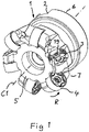
- a face milling tool 1 according to an embodiment of the invention is shown in Fig. 1 .
- the tool comprises a tool body 2 having six seats or pockets 3 each receiving a double-sided cutting insert 4 releasably fixed to the pocket.
- the cutting insert is removed from one of the pockets in Fig. 1 for illustrating the structure of the pockets.
- the tool body 2 includes a front end 5 and a rear end 6 between which a central rotation axis C1 extends around which the tool is rotatable in a direction of rotation R.
- the pockets 3 are formed in a transition between the front end and an envelope surface 7 extending between the front end and the rear end of the tool body.
- the double-sided inserts 4 are of the negative type, which are fixed in the pockets and tilted with an axial angle of -7° to -12° and a radial angle of -8° to -15° with respect to the central rotation axis C1 in order to provide clearance between the cutting inserts and workpiece.
- Other axial and radial angles are of course conceivable.
- Fig. 3 shows a cutting insert 4 according to an embodiment of the invention.
- the cutting insert is double-sided or reversible, which means that the top and bottom thereof have the same design, but the side shown with the orientation of the insert in the figure as the upper side will hereinafter be called the top, although it may just as well be the bottom or lower side of the insert.
- the insert has as seen in the figures a hidden lower surface 8, a top surface 9 and a surrounding side surface 10 connecting the lower surface and the top surface.
- the lower surface and the top surface are circular and have each a circular cutting edge 11, 12 formed between these surfaces and the side surface 10.
- the top surface 9 and the lower surface 8 are provided with a central recess 13 with a flat bottom surface 14.
- the recess 13 has six extended portions 15 of a valley- or finger-like design uniformly distributed around a centre axis C2 of the insert. These extended portions 15 are defined by border walls 16 of the recess and extend further radially with respect to said centre axis C2 than adjacent portions 17 of the recess.
- the insert is provided with a central axial through-hole 18 for securing it in a pocket 3 of the tool by a screw 19.
- Each pocket 3 has a portion 20 raised with respect to surrounding pocket portions 21 and provided with a flat support face 22 as upper surface.
- the raised portion 20 is configured to be received in the central recess 13 of the insert fixed in the pocket and provide support through the support face 22 to the bottom surface 14 of the recess.
- the pocket has also means configured to provide support to portions of the side surface 10 of an insert received in the pocket in the form of two separate support surfaces, one 23 for providing axial support and one 24 for providing radial support.
- These two support surfaces are formed by ridges with grooves therebetween, in which the grooves are manufactured by means of a ball nose end mill imparting a concavely arched shape thereto with the grooves having a depth being 0.015 to 0.025 mm.
- the raised portion 20 of the pocket has a first projecting member 25 configured to project into and be received in one extended recess portion 15 of the insert and engage portions 26 of recess border walls to establish mutual engagement of the insert and pocket to prevent rotation of the insert about the centre axis C2 of the insert by receiving a rotational moment acting on the insert in an active chip-removing state of the tool.
- the projecting member 25 carries said support face 22 to support the insert on the bottom surface 14 within a said extended recess portion 15.
- the first projecting member 25 is here directed at "six o'clock" with respect to the central rotation axis C1 of the tool which means in the direction of that axis, which means that it will provide support by the support face portion 27 thereon in the region of the insert configured to be exerted to a maximum load in an active chip-removing state of the tool and by that efficiently counteract any cracking or breaking tendency of the insert.
- the extended recess portions 15 are designed to allow said first projecting member to be designed to extend to a distance from said centre axis C2 of an insert received in the pocket being in the order of 90% of the distance from said centre axis to the side surface of the insert.
- the raised portion 20 is provided with two said projecting members and a second said projecting member 28 is configured to project into the extended recess portion 15 following upon the extended recess portion into which the first projecting member 25 is projecting as seen in the direction of a said rotational moment.
- the two projecting members are designed to project into a said extended recess portion with a clearance between delimiting walls 29 of the projecting member and the recess border walls 26 in the respective extended recess portion of the insert for simplifying mounting of the insert and avoiding that the seat of the pocket will be over-determined.
- the raised portion 20 of the pocket has a threaded bore 30 for receiving a screw 19 configured to secure the insert in the pocket.
- the bore 30 is located slightly offset with respect to the through-hole 18 of the insert, which means that the screw 19 will urge portions of the side surface 10 of the insert to bear under pretension against the support surfaces 23 and 24 of the pocket when the screw is tightened and then also press the bottom surface 14 of the central recess 13 of the insert against the support face 22 of the pocket.
- the insert may be indexed six times for having said first projecting member 25 received in each of the extended recess portions 15 and then reversed enabling 12 indexations of the insert.
- each central recess of the insert may be another than six.
- the insert may have a polygonal cross-section with a plurality of distinctive straight cutting edges along the upper and lower border thereof.
- the fastening means for securing the insert in the pocket may for instance be a clamp instead of a screw and the insert does then not need to have a central through-hole neither does the raised portion of the pocket then have to have a bore.
- the insert may be single-sided. Although the extended recess portions of the lower and the top surface are aligned with each other in the embodiment shown in the figures they may be displaced with respect to each other by any desired angle.
Landscapes
- Engineering & Computer Science (AREA)
- Mechanical Engineering (AREA)
- Milling Processes (AREA)
- Knives (AREA)
Claims (14)
- Schneidwerkzeug, bestehend aus:• einem Werkzeugkörper (2) mit wenigstens einer Tasche (3),• wenigstens einem Schneideinsatz (4), der lösbar an der Tasche befestigt ist, wobei der Einsatz eine untere Fläche (8), eine obere Fläche (9), eine umgebende Seitenfläche (10), die die untere Fläche und die obere Fläche verbindet, und wenigstens eine Schneidkante (11, 12), die zwischen der oberen Fläche und der Seitenfläche ausgebildet ist, aufweist,
wobei die Tasche Mittel (23, 24) aufweist, die so ausgestaltet sind, dass sie Abschnitte der Seitenfläche stützen, und eine flache Stützfläche (22), die so ausgestaltet ist, dass sie zumindest Abschnitte (14) der unteren Fläche des Einsatzes stützt, und• Befestigungsmitteln (19), die so ausgestaltet sind, dass sie den Einsatz (4) in der Tasche (3) befestigen, während sie die Abschnitte (14) der unteren Fläche gegen die Stützfläche (22) drücken,wobei der Einsatz ein erstes Eingriffselement (15) und die Tasche ein zweites Eingriffselement (25, 28) aufweist, die so ausgestaltet sind, dass sie einen gegenseitigen Eingriff des Einsatzes und der Tasche herstellen, um eine Drehung des Einsatzes um eine zentrale Einsatzachse (C2), die sich durch die obere Fläche und die untere Fläche des Einsatzes erstreckt, zu verhindern, indem sie ein Drehmoment aufnehmen, das auf den Einsatz in einem aktiven spanabhebenden Zustand des Werkzeugs wirkt,wobei die untere Fläche des Einsatzes eine zentrale Ausnehmung (13) mit einer flachen Bodenfläche (14) aufweist, wobei das erste Eingriffselement wenigstens zwei erweiterte Abschnitte (15) der Ausnehmung aufweist, die durch Randwände (16) der Ausnehmung definiert sind und sich bezogen auf die zentrale Achse weiter radial erstrecken als benachbarte Abschnitte (17) der Ausnehmung, und wobei das zweite Eingriffselement wenigstens ein feststehendes vorstehendes Element (25, 28) der Tasche (3) aufweist, das so konfiguriert ist, dass es alternativ in einen der erweiterten Abschnitte (15) der Ausnehmung und in die Eingriffsabschnitte der Randwände (16) der Ausnehmung hineinragt und darin aufgenommen wird, um den gegenseitigen Eingriff herzustellen und die Wendbarkeit des Einsatzes zu ermöglichen,wobei die Tasche des Werkzeugkörpers einen Abschnitt (20) aufweist, der in Bezug auf die umgebenden Taschenabschnitte (21) erhöht ist und die Stützfläche (22) als obere Fläche aufweist,wobei der erhöhte Abschnitt so gestaltet ist, dass er in der Ausnehmung (13) des Einsatzes (4) aufgenommen wird und den Einsatz stützt, indem er die Bodenfläche (14) der Ausnehmung (13) aufnimmt, die an der Stützfläche (22) anliegt,wobei das wenigstens eine vorstehende Element (25, 28) des zweiten Eingriffselements durch den erhöhten Abschnitt (20) ausgebildet wird, der Begrenzungswände (29) aufweist, die so ausgestaltet sind, dass sie an den Randwänden (16) der Ausnehmung des erweiterten Ausnehmungsabschnitts anliegen, um den gegenseitigen Eingriff zur Verhinderung einer Drehung zu bewirken,wobei der Einsatz (4) mit wenigstens drei der erweiterten Ausnehmungsabschnitte (15) versehen ist und das zweite Eingriffselement zwei der vorstehenden Elemente (25, 28) aufweist,dadurch gekennzeichnet, dass jedes der vorstehenden Elemente (25, 28) so gestaltet ist, dass es in einen der erweiterten Ausnehmungsabschnitte (15) mit Spiel zwischen den Begrenzungswänden (29) des vorstehenden Elements und den Randwänden (26) der Ausnehmung in den erweiterten Ausnehmungsabschnitt des Einsatzes hineinragt, und dass ein zweites vorstehendes Element der zwei festen vorstehenden Elemente (25, 28) einem größeres Spiel als ein erstes vorstehendes Element der zwei festen vorstehenden Elemente (25, 28) aufweist. - Schneidwerkzeug nach Anspruch 1, dadurch gekennzeichnet, dass das wenigstens eine vorstehende Element (25, 28) die Stützfläche (22) trägt, um den Einsatz auf der Bodenfläche (14) innerhalb eines erweiterten Ausnehmungsabschnitts (15) zu stützen.
- Schneidwerkzeug nach Anspruch 2, dadurch gekennzeichnet, dass das zweite Eingriffselement ein erstes der vorstehendes Element (25) aufweist, das so angeordnet ist, dass es den Einsatz über den Flächenabschnitt (27) in dem Bereich stützt, der so ausgestaltet ist, dass er in einem aktiven spanabhebenden Zustand des Werkzeugs einer Last ausgesetzt ist.
- Schneidwerkzeug nach Anspruch 3, dadurch gekennzeichnet, dass das erste vorstehende Element (25) in einer Richtung vorsteht, die von der zentralen Achse (C2) einer dieses Element aufnehmenden Wendeschneidplatte aus gesehen um 0-45° von einer entsprechenden Richtung abweicht, die auf einen Punkt der Schneidkante (11, 12) zeigt, der in einem aktiven spanabhebenden Zustand des Werkzeugs einer maximalen Belastung ausgesetzt ist.
- Schneidwerkzeug nach einem der Ansprüche 2 bis 4, dadurch gekennzeichnet, dass das erste vorstehende Element (25), wenn es in einem erweiterten Ausnehmungsabschnitt (15) aufgenommen ist, so ausgestaltet ist, dass es sich bis zu einem Abstand von der zentralen Achse (C2) erstreckt, der wenigstens 70%, 75%-95% oder 80%-90% des Abstands von der zentralen Achse zu der Seitenfläche (10) des Einsatzes beträgt.
- Schneidwerkzeug nach Anspruch 1 in Abhängigkeit von einem der Ansprüche 3 bis 5, dadurch gekennzeichnet, dass ein zweites (28) der zwei vorstehenden Elemente so konfiguriert ist, dass es in den erweiterten Ausnehmungsabschnitt (15) ragt, der in Richtung eines auf den Einsatz wirkenden Drehmoments betrachtet auf den erweiterten Ausnehmungsabschnitt folgt, in den das erste vorstehende Element (25) ragt.
- Schneidwerkzeug nach einem der vorhergehenden Ansprüche, dadurch gekennzeichnet, dass die Ausnehmung (13) mit einer Mehrzahl von tal- oder fingerartigen Ausnehmungen (15) versehen ist, die gleichmäßig um die zentrale Achse (C2) des Einsatzes verteilt sind.
- Schneidwerkzeug nach Anspruch 7, dadurch gekennzeichnet, dass der Einsatz 5-8, 6-8 oder 6 der erweiterten Ausnehmungsabschnitte (15) in der zentralen Ausnehmung (13) aufweist.
- Schneidwerkzeug nach einem der vorhergehenden Ansprüche, dadurch gekennzeichnet, dass die obere Fläche (9) des Einsatzes kreisförmig ist und die Schneidkante (12) kreisförmig ist.
- Schneidwerkzeug nach einem der vorhergehenden Ansprüche, dadurch gekennzeichnet, dass der Einsatz (4) in dem Sinne wendbar ist, dass die untere (8) und die obere (9) Fläche desselben identisch sind und eine Schneidkante (11, 12) zwischen jeder dieser Flächen und der Seitenfläche (10) des Einsatzes ausgebildet ist.
- Schneidwerkzeug nach einem der vorhergehenden Ansprüche, dadurch gekennzeichnet, dass die Mittel zur Stützung von Teilen der Seitenfläche (10) des Einsatzes wenigstens eine Stützfläche (23, 24) aufweisen, die wenigstens drei Rippen mit Nuten dazwischen aufweisen, wobei die Nuten mit Hilfe eines Kugelkopffräsers hergestellt werden, der ihnen eine konkav gewölbte Form verleiht, und wobei die Nuten eine Tiefe von 0,015 bis 0,025 mm aufweisen.
- Schneidwerkzeug nach einem der vorhergehenden Ansprüche, dadurch gekennzeichnet, dass es sich um ein Fräswerkzeug handelt, wobei der Werkzeugkörper (2) ein vorderes Ende (5) und ein hinteres Ende (6) aufweist, zwischen denen sich eine zentrale Rotationsachse (C1) erstreckt, um die das Werkzeug in einer Rotationsrichtung rotierbar ist, und dass die Tasche (3) in einem Übergang zwischen dem vorderen Ende (5) und einer sich zwischen dem vorderen Ende und dem hinteren Ende des Werkzeugkörpers erstreckenden Mantelfläche verläuft.
- Schneidwerkzeug nach Anspruch 12, dadurch gekennzeichnet, dass das Mittel, welches so konfiguriert ist, dass es Abschnitte der Seitenfläche (10) des Einsatzes stützt, zwei getrennte Stützflächen (23, 24) aufweist, die den Einsatz axial bzw. radial in Bezug auf die zentrale Rotationsachse (C1) des Werkzeugs stützen.
- Schneidwerkzeug nach Anspruch 3 und 12 oder 13, dadurch gekennzeichnet, dass das erste vorstehende Element (25) in einer Richtung vorsteht, die in Bezug auf die Verlängerung der zentralen Rotationsachse (C1) des Werkzeugs um 0°-45°, 0°-25° oder 0°-5° abweicht.
Priority Applications (8)
| Application Number | Priority Date | Filing Date | Title |
|---|---|---|---|
| EP14186207.8A EP3000549B1 (de) | 2014-09-24 | 2014-09-24 | Schneidwerkzeug und Schneideinsatz für ein spanabhebendes Werkzeug |
| JP2017516456A JP6762294B2 (ja) | 2014-09-24 | 2015-09-03 | 切削工具及び切屑除去工具用切削インサート |
| KR1020177007511A KR102362021B1 (ko) | 2014-09-24 | 2015-09-03 | 칩 제거 공구용의 절삭 공구 및 절삭 인서트 |
| CN202211242988.3A CN115502456B (zh) | 2014-09-24 | 2015-09-03 | 切削刀具及去屑刀具的切削刀片 |
| BR112017006055A BR112017006055A2 (pt) | 2014-09-24 | 2015-09-03 | uma ferramenta de corte e uma pastilha de corte para uma ferramenta de remoção de cavaco |
| US15/513,591 US10252355B2 (en) | 2014-09-24 | 2015-09-03 | Cutting tool and a cutting insert for chip-removing tool |
| PCT/EP2015/070131 WO2016045928A1 (en) | 2014-09-24 | 2015-09-03 | A cutting tool and a cutting insert for a chip-removing tool |
| CN201580047212.8A CN106660148A (zh) | 2014-09-24 | 2015-09-03 | 切削刀具及去屑刀具的切削刀片 |
Applications Claiming Priority (1)
| Application Number | Priority Date | Filing Date | Title |
|---|---|---|---|
| EP14186207.8A EP3000549B1 (de) | 2014-09-24 | 2014-09-24 | Schneidwerkzeug und Schneideinsatz für ein spanabhebendes Werkzeug |
Publications (2)
| Publication Number | Publication Date |
|---|---|
| EP3000549A1 EP3000549A1 (de) | 2016-03-30 |
| EP3000549B1 true EP3000549B1 (de) | 2022-11-09 |
Family
ID=51585043
Family Applications (1)
| Application Number | Title | Priority Date | Filing Date |
|---|---|---|---|
| EP14186207.8A Active EP3000549B1 (de) | 2014-09-24 | 2014-09-24 | Schneidwerkzeug und Schneideinsatz für ein spanabhebendes Werkzeug |
Country Status (7)
| Country | Link |
|---|---|
| US (1) | US10252355B2 (de) |
| EP (1) | EP3000549B1 (de) |
| JP (1) | JP6762294B2 (de) |
| KR (1) | KR102362021B1 (de) |
| CN (2) | CN106660148A (de) |
| BR (1) | BR112017006055A2 (de) |
| WO (1) | WO2016045928A1 (de) |
Families Citing this family (7)
| Publication number | Priority date | Publication date | Assignee | Title |
|---|---|---|---|---|
| EP3351329B1 (de) * | 2017-01-18 | 2023-08-02 | Sandvik Intellectual Property AB | Indexierbarer schneideeinsatz für ein fräswerkzeug |
| US10646927B2 (en) * | 2018-02-19 | 2020-05-12 | Iscar, Ltd. | Round double-sided cutting insert having a peripheral surface provided with protruding indexing latches, insert holder therefor and cutting tool |
| EP3560644B1 (de) * | 2018-04-27 | 2022-10-05 | Seco Tools Ab | Werkzeugkörper und fräswerkzeug |
| JP7012948B1 (ja) * | 2021-03-10 | 2022-01-31 | 株式会社タンガロイ | 刃先交換式切削工具の工具本体 |
| US11786982B2 (en) | 2021-04-26 | 2023-10-17 | Kennametal Inc. | Cutting tool comprising toolholder and round cutting insert and method for repositioning the round cutting insert in a pocket of the toolholder |
| US12544841B2 (en) | 2021-04-26 | 2026-02-10 | Kennametal Inc. | Cutting tool comprising toolholder and round cutting insert and method for repositioning the round cutting insert in a pocket of the toolholder |
| CN113275635B (zh) * | 2021-05-21 | 2022-10-11 | 株洲华锐精密工具股份有限公司 | 一种切削刀具 |
Citations (1)
| Publication number | Priority date | Publication date | Assignee | Title |
|---|---|---|---|---|
| JP2013075337A (ja) * | 2011-09-30 | 2013-04-25 | Hitachi Tool Engineering Ltd | 刃先交換式切削工具 |
Family Cites Families (24)
| Publication number | Priority date | Publication date | Assignee | Title |
|---|---|---|---|---|
| US3662444A (en) * | 1970-03-09 | 1972-05-16 | Ingersoll Milling Machine Co | Indexable cutting insert and holder therefor |
| SE505511C2 (sv) * | 1994-12-15 | 1997-09-08 | Sandvik Ab | Fräskropp samt förfarande för tillverkning av denna |
| SE516501C2 (sv) * | 2000-05-18 | 2002-01-22 | Sandvik Ab | Verktygskoppling |
| JP2003117717A (ja) * | 2000-10-27 | 2003-04-23 | Sumitomo Electric Ind Ltd | ワイパーチップおよび回転切削工具用ワイパーチップ |
| SE525913C2 (sv) * | 2002-12-20 | 2005-05-24 | Seco Tools Ab | Skär, verktyg samt metod för montering av skär där skäret kan orienteras i önskad position |
| DE10338276B4 (de) * | 2003-08-15 | 2008-05-21 | NUBIUS GROUP Präzisionswerkzeuge GmbH | Fräswerkzeug |
| SE527543C2 (sv) * | 2004-08-30 | 2006-04-04 | Sandvik Intellectual Property | Skärläge med spårförsedd stödyta |
| SE530181C2 (sv) * | 2005-12-21 | 2008-03-18 | Sandvik Intellectual Property | Verktyg för spånavskiljande bearbetning samt grundkropp och separat låsorgan härför |
| IL182343A0 (en) * | 2007-04-01 | 2007-07-24 | Iscar Ltd | Cutting insert and tool for milling and ramping at high feed rates |
| SE531502C2 (sv) * | 2007-06-05 | 2009-04-28 | Sandvik Intellectual Property | Verktyg för spånavskiljande bearbetning samt grundkropp och indexerbart skär härför |
| US9149878B2 (en) * | 2008-06-26 | 2015-10-06 | Seco Tools Ab | Family of cutting inserts, milling cutting tool, and cutting insert |
| AT11470U1 (de) * | 2009-06-10 | 2010-11-15 | Ceratizit Austria Gmbh | Schneidwerkzeug |
| US8573903B2 (en) * | 2009-11-03 | 2013-11-05 | Kennametal Inc. | Round cutting insert with anti-rotation feature |
| US8657539B2 (en) * | 2011-03-28 | 2014-02-25 | Kennametal Inc. | Round cutting insert with reverse anti-rotation feature |
| CN103842119B (zh) * | 2011-10-07 | 2016-12-14 | 株式会社钨钛合金 | 刀头更换式切削工具 |
| SE536345C2 (sv) * | 2012-01-20 | 2013-09-03 | Sandvik Intellectual Property | Håltagningsverktyg med bytbart skär innefattande han- och honartade säkringsmedel |
| SE536344C2 (sv) * | 2012-01-30 | 2013-09-03 | Sandvik Intellectual Property | Fräsverktyg jämte frässkär där skäreggen har spetsig stigningsvinkel |
| US8858130B2 (en) * | 2012-04-24 | 2014-10-14 | Kennametal Inc. | Indexable circular cutting insert |
| US20130330136A1 (en) * | 2012-06-06 | 2013-12-12 | Iscar, Ltd. | Cutting Insert and Tool Having an Anti-Slip Arrangement |
| US9283626B2 (en) * | 2012-09-25 | 2016-03-15 | Kennametal Inc. | Double-sided cutting inserts with anti-rotation features |
| US9011049B2 (en) * | 2012-09-25 | 2015-04-21 | Kennametal Inc. | Double-sided cutting inserts with anti-rotation features |
| EP3162481B1 (de) * | 2014-06-24 | 2022-12-21 | Sumitomo Electric Hardmetal Corp. | Schneidwerkzeug und werkzeugkörper |
| US10406608B2 (en) * | 2015-01-19 | 2019-09-10 | Kennametal Inc. | Cutting insert and pocket with uninterrupted and continuous seating surface perimeter |
| CN107073605B (zh) * | 2015-02-19 | 2019-07-30 | 株式会社泰珂洛 | 刀具主体、刀片支承机构以及切削刀具 |
-
2014
- 2014-09-24 EP EP14186207.8A patent/EP3000549B1/de active Active
-
2015
- 2015-09-03 BR BR112017006055A patent/BR112017006055A2/pt not_active Application Discontinuation
- 2015-09-03 US US15/513,591 patent/US10252355B2/en active Active
- 2015-09-03 KR KR1020177007511A patent/KR102362021B1/ko active Active
- 2015-09-03 JP JP2017516456A patent/JP6762294B2/ja active Active
- 2015-09-03 WO PCT/EP2015/070131 patent/WO2016045928A1/en not_active Ceased
- 2015-09-03 CN CN201580047212.8A patent/CN106660148A/zh active Pending
- 2015-09-03 CN CN202211242988.3A patent/CN115502456B/zh active Active
Patent Citations (1)
| Publication number | Priority date | Publication date | Assignee | Title |
|---|---|---|---|---|
| JP2013075337A (ja) * | 2011-09-30 | 2013-04-25 | Hitachi Tool Engineering Ltd | 刃先交換式切削工具 |
Also Published As
| Publication number | Publication date |
|---|---|
| JP6762294B2 (ja) | 2020-09-30 |
| JP2017528330A (ja) | 2017-09-28 |
| US20170291233A1 (en) | 2017-10-12 |
| KR20170058373A (ko) | 2017-05-26 |
| EP3000549A1 (de) | 2016-03-30 |
| CN106660148A (zh) | 2017-05-10 |
| CN115502456A (zh) | 2022-12-23 |
| WO2016045928A1 (en) | 2016-03-31 |
| KR102362021B1 (ko) | 2022-02-10 |
| BR112017006055A2 (pt) | 2017-12-19 |
| US10252355B2 (en) | 2019-04-09 |
| CN115502456B (zh) | 2026-03-17 |
Similar Documents
| Publication | Publication Date | Title |
|---|---|---|
| EP3000549B1 (de) | Schneidwerkzeug und Schneideinsatz für ein spanabhebendes Werkzeug | |
| EP3199284B1 (de) | Wendeschneidplatte für einen schaftfräser und mit solch einer schneidplatte ausgestatteter schaftfräser | |
| CN107107209A (zh) | 切削刀片和铣削刀具 | |
| KR20170086513A (ko) | 스퀘어 숄더 밀링용 절삭 인서트 및 절삭 공구 | |
| US20160207124A1 (en) | Cutting insert and pocket with uninterrupted and continuous seating surface perimeter | |
| EP3924128B1 (de) | Rotationsschneidkörper mit einsatztasche mit sitzfläche mit einer vielzahl von anschlagelementen, drehschneidwerkzeug und einsatz | |
| KR102379492B1 (ko) | 절삭 인서트 및 숄더 밀링 공구 | |
| CN110114177B (zh) | 用于铣削刀具的可转位切削刀片 | |
| US20190160563A1 (en) | Single-sided four-way indexable positive cutting insert and insert mill therefor | |
| EP2730360A1 (de) | Schneideeinsatz und schneidewerkzeug | |
| US7357603B2 (en) | Toolholder and cutting insert used therein | |
| US8540462B2 (en) | Shim plate for tools for cutting machining as well as a tool | |
| US10906107B2 (en) | Single-sided four-way indexable positive cutting insert and insert mill therefor | |
| JP7335239B2 (ja) | 片面四方向割出し可能でポジティブな切削インサートおよびそのためのインサートミル | |
| KR20060135212A (ko) | 절삭 인서트 |
Legal Events
| Date | Code | Title | Description |
|---|---|---|---|
| PUAI | Public reference made under article 153(3) epc to a published international application that has entered the european phase |
Free format text: ORIGINAL CODE: 0009012 |
|
| AK | Designated contracting states |
Kind code of ref document: A1 Designated state(s): AL AT BE BG CH CY CZ DE DK EE ES FI FR GB GR HR HU IE IS IT LI LT LU LV MC MK MT NL NO PL PT RO RS SE SI SK SM TR |
|
| AX | Request for extension of the european patent |
Extension state: BA ME |
|
| 17P | Request for examination filed |
Effective date: 20160930 |
|
| RBV | Designated contracting states (corrected) |
Designated state(s): AL AT BE BG CH CY CZ DE DK EE ES FI FR GB GR HR HU IE IS IT LI LT LU LV MC MK MT NL NO PL PT RO RS SE SI SK SM TR |
|
| STAA | Information on the status of an ep patent application or granted ep patent |
Free format text: STATUS: EXAMINATION IS IN PROGRESS |
|
| 17Q | First examination report despatched |
Effective date: 20190605 |
|
| GRAP | Despatch of communication of intention to grant a patent |
Free format text: ORIGINAL CODE: EPIDOSNIGR1 |
|
| STAA | Information on the status of an ep patent application or granted ep patent |
Free format text: STATUS: GRANT OF PATENT IS INTENDED |
|
| INTG | Intention to grant announced |
Effective date: 20220504 |
|
| RIN1 | Information on inventor provided before grant (corrected) |
Inventor name: MARIE, GILLES Inventor name: RUE, MARC Inventor name: GASTHUYS, JACQUES |
|
| GRAS | Grant fee paid |
Free format text: ORIGINAL CODE: EPIDOSNIGR3 |
|
| GRAA | (expected) grant |
Free format text: ORIGINAL CODE: 0009210 |
|
| STAA | Information on the status of an ep patent application or granted ep patent |
Free format text: STATUS: THE PATENT HAS BEEN GRANTED |
|
| AK | Designated contracting states |
Kind code of ref document: B1 Designated state(s): AL AT BE BG CH CY CZ DE DK EE ES FI FR GB GR HR HU IE IS IT LI LT LU LV MC MK MT NL NO PL PT RO RS SE SI SK SM TR |
|
| REG | Reference to a national code |
Ref country code: GB Ref legal event code: FG4D |
|
| REG | Reference to a national code |
Ref country code: CH Ref legal event code: EP Ref country code: AT Ref legal event code: REF Ref document number: 1530033 Country of ref document: AT Kind code of ref document: T Effective date: 20221115 |
|
| REG | Reference to a national code |
Ref country code: DE Ref legal event code: R096 Ref document number: 602014085465 Country of ref document: DE |
|
| REG | Reference to a national code |
Ref country code: IE Ref legal event code: FG4D |
|
| REG | Reference to a national code |
Ref country code: LT Ref legal event code: MG9D |
|
| REG | Reference to a national code |
Ref country code: NL Ref legal event code: MP Effective date: 20221109 |
|
| REG | Reference to a national code |
Ref country code: AT Ref legal event code: MK05 Ref document number: 1530033 Country of ref document: AT Kind code of ref document: T Effective date: 20221109 |
|
| PG25 | Lapsed in a contracting state [announced via postgrant information from national office to epo] |
Ref country code: SE Free format text: LAPSE BECAUSE OF FAILURE TO SUBMIT A TRANSLATION OF THE DESCRIPTION OR TO PAY THE FEE WITHIN THE PRESCRIBED TIME-LIMIT Effective date: 20221109 Ref country code: PT Free format text: LAPSE BECAUSE OF FAILURE TO SUBMIT A TRANSLATION OF THE DESCRIPTION OR TO PAY THE FEE WITHIN THE PRESCRIBED TIME-LIMIT Effective date: 20230309 Ref country code: NO Free format text: LAPSE BECAUSE OF FAILURE TO SUBMIT A TRANSLATION OF THE DESCRIPTION OR TO PAY THE FEE WITHIN THE PRESCRIBED TIME-LIMIT Effective date: 20230209 Ref country code: LT Free format text: LAPSE BECAUSE OF FAILURE TO SUBMIT A TRANSLATION OF THE DESCRIPTION OR TO PAY THE FEE WITHIN THE PRESCRIBED TIME-LIMIT Effective date: 20221109 Ref country code: FI Free format text: LAPSE BECAUSE OF FAILURE TO SUBMIT A TRANSLATION OF THE DESCRIPTION OR TO PAY THE FEE WITHIN THE PRESCRIBED TIME-LIMIT Effective date: 20221109 Ref country code: ES Free format text: LAPSE BECAUSE OF FAILURE TO SUBMIT A TRANSLATION OF THE DESCRIPTION OR TO PAY THE FEE WITHIN THE PRESCRIBED TIME-LIMIT Effective date: 20221109 Ref country code: AT Free format text: LAPSE BECAUSE OF FAILURE TO SUBMIT A TRANSLATION OF THE DESCRIPTION OR TO PAY THE FEE WITHIN THE PRESCRIBED TIME-LIMIT Effective date: 20221109 |
|
| PG25 | Lapsed in a contracting state [announced via postgrant information from national office to epo] |
Ref country code: RS Free format text: LAPSE BECAUSE OF FAILURE TO SUBMIT A TRANSLATION OF THE DESCRIPTION OR TO PAY THE FEE WITHIN THE PRESCRIBED TIME-LIMIT Effective date: 20221109 Ref country code: PL Free format text: LAPSE BECAUSE OF FAILURE TO SUBMIT A TRANSLATION OF THE DESCRIPTION OR TO PAY THE FEE WITHIN THE PRESCRIBED TIME-LIMIT Effective date: 20221109 Ref country code: LV Free format text: LAPSE BECAUSE OF FAILURE TO SUBMIT A TRANSLATION OF THE DESCRIPTION OR TO PAY THE FEE WITHIN THE PRESCRIBED TIME-LIMIT Effective date: 20221109 Ref country code: IS Free format text: LAPSE BECAUSE OF FAILURE TO SUBMIT A TRANSLATION OF THE DESCRIPTION OR TO PAY THE FEE WITHIN THE PRESCRIBED TIME-LIMIT Effective date: 20230309 Ref country code: HR Free format text: LAPSE BECAUSE OF FAILURE TO SUBMIT A TRANSLATION OF THE DESCRIPTION OR TO PAY THE FEE WITHIN THE PRESCRIBED TIME-LIMIT Effective date: 20221109 Ref country code: GR Free format text: LAPSE BECAUSE OF FAILURE TO SUBMIT A TRANSLATION OF THE DESCRIPTION OR TO PAY THE FEE WITHIN THE PRESCRIBED TIME-LIMIT Effective date: 20230210 |
|
| PG25 | Lapsed in a contracting state [announced via postgrant information from national office to epo] |
Ref country code: NL Free format text: LAPSE BECAUSE OF FAILURE TO SUBMIT A TRANSLATION OF THE DESCRIPTION OR TO PAY THE FEE WITHIN THE PRESCRIBED TIME-LIMIT Effective date: 20221109 |
|
| P01 | Opt-out of the competence of the unified patent court (upc) registered |
Effective date: 20230603 |
|
| PG25 | Lapsed in a contracting state [announced via postgrant information from national office to epo] |
Ref country code: SM Free format text: LAPSE BECAUSE OF FAILURE TO SUBMIT A TRANSLATION OF THE DESCRIPTION OR TO PAY THE FEE WITHIN THE PRESCRIBED TIME-LIMIT Effective date: 20221109 Ref country code: RO Free format text: LAPSE BECAUSE OF FAILURE TO SUBMIT A TRANSLATION OF THE DESCRIPTION OR TO PAY THE FEE WITHIN THE PRESCRIBED TIME-LIMIT Effective date: 20221109 Ref country code: EE Free format text: LAPSE BECAUSE OF FAILURE TO SUBMIT A TRANSLATION OF THE DESCRIPTION OR TO PAY THE FEE WITHIN THE PRESCRIBED TIME-LIMIT Effective date: 20221109 Ref country code: DK Free format text: LAPSE BECAUSE OF FAILURE TO SUBMIT A TRANSLATION OF THE DESCRIPTION OR TO PAY THE FEE WITHIN THE PRESCRIBED TIME-LIMIT Effective date: 20221109 Ref country code: CZ Free format text: LAPSE BECAUSE OF FAILURE TO SUBMIT A TRANSLATION OF THE DESCRIPTION OR TO PAY THE FEE WITHIN THE PRESCRIBED TIME-LIMIT Effective date: 20221109 |
|
| REG | Reference to a national code |
Ref country code: DE Ref legal event code: R097 Ref document number: 602014085465 Country of ref document: DE |
|
| PG25 | Lapsed in a contracting state [announced via postgrant information from national office to epo] |
Ref country code: SK Free format text: LAPSE BECAUSE OF FAILURE TO SUBMIT A TRANSLATION OF THE DESCRIPTION OR TO PAY THE FEE WITHIN THE PRESCRIBED TIME-LIMIT Effective date: 20221109 Ref country code: AL Free format text: LAPSE BECAUSE OF FAILURE TO SUBMIT A TRANSLATION OF THE DESCRIPTION OR TO PAY THE FEE WITHIN THE PRESCRIBED TIME-LIMIT Effective date: 20221109 |
|
| PLBE | No opposition filed within time limit |
Free format text: ORIGINAL CODE: 0009261 |
|
| STAA | Information on the status of an ep patent application or granted ep patent |
Free format text: STATUS: NO OPPOSITION FILED WITHIN TIME LIMIT |
|
| 26N | No opposition filed |
Effective date: 20230810 |
|
| PG25 | Lapsed in a contracting state [announced via postgrant information from national office to epo] |
Ref country code: SI Free format text: LAPSE BECAUSE OF FAILURE TO SUBMIT A TRANSLATION OF THE DESCRIPTION OR TO PAY THE FEE WITHIN THE PRESCRIBED TIME-LIMIT Effective date: 20221109 |
|
| REG | Reference to a national code |
Ref country code: CH Ref legal event code: PL |
|
| PG25 | Lapsed in a contracting state [announced via postgrant information from national office to epo] |
Ref country code: LU Free format text: LAPSE BECAUSE OF NON-PAYMENT OF DUE FEES Effective date: 20230924 |
|
| REG | Reference to a national code |
Ref country code: BE Ref legal event code: MM Effective date: 20230930 |
|
| PG25 | Lapsed in a contracting state [announced via postgrant information from national office to epo] |
Ref country code: LU Free format text: LAPSE BECAUSE OF NON-PAYMENT OF DUE FEES Effective date: 20230924 Ref country code: MC Free format text: LAPSE BECAUSE OF FAILURE TO SUBMIT A TRANSLATION OF THE DESCRIPTION OR TO PAY THE FEE WITHIN THE PRESCRIBED TIME-LIMIT Effective date: 20221109 |
|
| REG | Reference to a national code |
Ref country code: IE Ref legal event code: MM4A |
|
| PG25 | Lapsed in a contracting state [announced via postgrant information from national office to epo] |
Ref country code: IE Free format text: LAPSE BECAUSE OF NON-PAYMENT OF DUE FEES Effective date: 20230924 |
|
| PG25 | Lapsed in a contracting state [announced via postgrant information from national office to epo] |
Ref country code: CH Free format text: LAPSE BECAUSE OF NON-PAYMENT OF DUE FEES Effective date: 20230930 |
|
| PG25 | Lapsed in a contracting state [announced via postgrant information from national office to epo] |
Ref country code: IE Free format text: LAPSE BECAUSE OF NON-PAYMENT OF DUE FEES Effective date: 20230924 Ref country code: CH Free format text: LAPSE BECAUSE OF NON-PAYMENT OF DUE FEES Effective date: 20230930 |
|
| PG25 | Lapsed in a contracting state [announced via postgrant information from national office to epo] |
Ref country code: BE Free format text: LAPSE BECAUSE OF NON-PAYMENT OF DUE FEES Effective date: 20230930 |
|
| PG25 | Lapsed in a contracting state [announced via postgrant information from national office to epo] |
Ref country code: BG Free format text: LAPSE BECAUSE OF FAILURE TO SUBMIT A TRANSLATION OF THE DESCRIPTION OR TO PAY THE FEE WITHIN THE PRESCRIBED TIME-LIMIT Effective date: 20221109 |
|
| PG25 | Lapsed in a contracting state [announced via postgrant information from national office to epo] |
Ref country code: BG Free format text: LAPSE BECAUSE OF FAILURE TO SUBMIT A TRANSLATION OF THE DESCRIPTION OR TO PAY THE FEE WITHIN THE PRESCRIBED TIME-LIMIT Effective date: 20221109 |
|
| PG25 | Lapsed in a contracting state [announced via postgrant information from national office to epo] |
Ref country code: CY Free format text: LAPSE BECAUSE OF FAILURE TO SUBMIT A TRANSLATION OF THE DESCRIPTION OR TO PAY THE FEE WITHIN THE PRESCRIBED TIME-LIMIT; INVALID AB INITIO Effective date: 20140924 |
|
| PG25 | Lapsed in a contracting state [announced via postgrant information from national office to epo] |
Ref country code: HU Free format text: LAPSE BECAUSE OF FAILURE TO SUBMIT A TRANSLATION OF THE DESCRIPTION OR TO PAY THE FEE WITHIN THE PRESCRIBED TIME-LIMIT; INVALID AB INITIO Effective date: 20140924 |
|
| PGFP | Annual fee paid to national office [announced via postgrant information from national office to epo] |
Ref country code: DE Payment date: 20250730 Year of fee payment: 12 |
|
| PGFP | Annual fee paid to national office [announced via postgrant information from national office to epo] |
Ref country code: IT Payment date: 20250825 Year of fee payment: 12 |
|
| PGFP | Annual fee paid to national office [announced via postgrant information from national office to epo] |
Ref country code: GB Payment date: 20250731 Year of fee payment: 12 |
|
| PGFP | Annual fee paid to national office [announced via postgrant information from national office to epo] |
Ref country code: FR Payment date: 20250821 Year of fee payment: 12 |
|
| PG25 | Lapsed in a contracting state [announced via postgrant information from national office to epo] |
Ref country code: TR Free format text: LAPSE BECAUSE OF FAILURE TO SUBMIT A TRANSLATION OF THE DESCRIPTION OR TO PAY THE FEE WITHIN THE PRESCRIBED TIME-LIMIT Effective date: 20221109 |