EP3000549A1 - Schneidwerkzeug und Schneideinsatz für ein spanabhebendes Werkzeug - Google Patents
Schneidwerkzeug und Schneideinsatz für ein spanabhebendes Werkzeug Download PDFInfo
- Publication number
- EP3000549A1 EP3000549A1 EP14186207.8A EP14186207A EP3000549A1 EP 3000549 A1 EP3000549 A1 EP 3000549A1 EP 14186207 A EP14186207 A EP 14186207A EP 3000549 A1 EP3000549 A1 EP 3000549A1
- Authority
- EP
- European Patent Office
- Prior art keywords
- insert
- recess
- cutting
- portions
- Prior art date
- Legal status (The legal status is an assumption and is not a legal conclusion. Google has not performed a legal analysis and makes no representation as to the accuracy of the status listed.)
- Granted
Links
Images

Classifications
-
- B—PERFORMING OPERATIONS; TRANSPORTING
- B23—MACHINE TOOLS; METAL-WORKING NOT OTHERWISE PROVIDED FOR
- B23C—MILLING
- B23C5/00—Milling-cutters
- B23C5/16—Milling-cutters characterised by physical features other than shape
- B23C5/20—Milling-cutters characterised by physical features other than shape with removable cutter bits or teeth or cutting inserts
- B23C5/22—Securing arrangements for bits or teeth or cutting inserts
- B23C5/2204—Securing arrangements for bits or teeth or cutting inserts with cutting inserts clamped against the walls of the recess in the cutter body by a clamping member acting upon the wall of a hole in the insert
- B23C5/2208—Securing arrangements for bits or teeth or cutting inserts with cutting inserts clamped against the walls of the recess in the cutter body by a clamping member acting upon the wall of a hole in the insert for plate-like cutting inserts
- B23C5/2213—Securing arrangements for bits or teeth or cutting inserts with cutting inserts clamped against the walls of the recess in the cutter body by a clamping member acting upon the wall of a hole in the insert for plate-like cutting inserts having a special shape
-
- B—PERFORMING OPERATIONS; TRANSPORTING
- B23—MACHINE TOOLS; METAL-WORKING NOT OTHERWISE PROVIDED FOR
- B23C—MILLING
- B23C5/00—Milling-cutters
- B23C5/02—Milling-cutters characterised by the shape of the cutter
- B23C5/06—Face-milling cutters, i.e. having only or primarily a substantially flat cutting surface
-
- B—PERFORMING OPERATIONS; TRANSPORTING
- B23—MACHINE TOOLS; METAL-WORKING NOT OTHERWISE PROVIDED FOR
- B23C—MILLING
- B23C5/00—Milling-cutters
- B23C5/16—Milling-cutters characterised by physical features other than shape
- B23C5/20—Milling-cutters characterised by physical features other than shape with removable cutter bits or teeth or cutting inserts
- B23C5/22—Securing arrangements for bits or teeth or cutting inserts
- B23C5/2239—Securing arrangements for bits or teeth or cutting inserts with cutting inserts clamped by a clamping member acting almost perpendicular on the cutting face
- B23C5/2243—Securing arrangements for bits or teeth or cutting inserts with cutting inserts clamped by a clamping member acting almost perpendicular on the cutting face for plate-like cutting inserts
- B23C5/2247—Securing arrangements for bits or teeth or cutting inserts with cutting inserts clamped by a clamping member acting almost perpendicular on the cutting face for plate-like cutting inserts having a special shape
-
- B—PERFORMING OPERATIONS; TRANSPORTING
- B23—MACHINE TOOLS; METAL-WORKING NOT OTHERWISE PROVIDED FOR
- B23C—MILLING
- B23C2200/00—Details of milling cutting inserts
- B23C2200/04—Overall shape
- B23C2200/045—Round
-
- B—PERFORMING OPERATIONS; TRANSPORTING
- B23—MACHINE TOOLS; METAL-WORKING NOT OTHERWISE PROVIDED FOR
- B23C—MILLING
- B23C2200/00—Details of milling cutting inserts
- B23C2200/16—Supporting or bottom surfaces
- B23C2200/165—Supporting or bottom surfaces with one or more grooves
-
- B—PERFORMING OPERATIONS; TRANSPORTING
- B23—MACHINE TOOLS; METAL-WORKING NOT OTHERWISE PROVIDED FOR
- B23C—MILLING
- B23C2200/00—Details of milling cutting inserts
- B23C2200/16—Supporting or bottom surfaces
- B23C2200/168—Supporting or bottom surfaces with features related to indexing
-
- B—PERFORMING OPERATIONS; TRANSPORTING
- B23—MACHINE TOOLS; METAL-WORKING NOT OTHERWISE PROVIDED FOR
- B23C—MILLING
- B23C2210/00—Details of milling cutters
- B23C2210/16—Fixation of inserts or cutting bits in the tool
- B23C2210/163—Indexing
-
- B—PERFORMING OPERATIONS; TRANSPORTING
- B23—MACHINE TOOLS; METAL-WORKING NOT OTHERWISE PROVIDED FOR
- B23C—MILLING
- B23C2210/00—Details of milling cutters
- B23C2210/16—Fixation of inserts or cutting bits in the tool
- B23C2210/168—Seats for cutting inserts, supports for replacable cutting bits
Definitions
- the present invention relates to a cutting tool configured for chip-removing machining according to the preamble of claim 1 comprising a tool body and at least one cutting insert as well as such a cutting insert according to the preamble of claim 17.
- Such milling tools have normally a plurality of, for example six, pockets to which a cutting insert is releasably fixed for enabling indexing of the cutting insert for changing the portion of the cutting edge thereof used for chip-removing machining. It is of vital importance for the result of said machining and the lifetime of said cutting insert that the insert received in said pocket or seat of the tool body is properly supported in a fixed position therein.
- Such support is to be provided by said means providing support to portions of the side surface of the insert and said flat support face providing support to the lower surface of the insert and against which fastening means is pressing the lower surface while securing the insert in a said pocket. It is also important that the insert may not move when a rotational moment is acting thereupon in an active chip-removing state of the tool, and that is ensured by an engagement member of the insert interacting with an engagement member of the pocket.
- EP 2 764 939 A1 discloses a cutting tool and a cutting insert of the type defined in the introduction.
- the support face of the pocket is in that tool provided by a flat pocket bottom surface onto which the portions of said lower surface of the insert surrounding said central recess are applied for receiving support thereby.
- An engagement member is arranged on top of that support face so as to be received in said recess and forming a projecting member for obtaining engagement with a specific extended recess portion and prevent rotation of the insert in said active chip-removing state of the tool.
- the object of the present invention is to provide a cutting tool and a cutting insert of the type defined in the introduction being improved in at least some aspect with respect to such cutting tools and cutting inserts already known.
- said at least one projecting member carries said support face to support the insert on said bottom surface within said extended recess portion. This means that said support face will come close to the outer border of a recess receiving said projecting member improving the protection and support of portions of the insert exerted to cutting forces in the active chip-removing state of the tool.
- said insert is provided with at least three said extended recess portions, and said second engagement member comprises two said projecting members.
- the arrangement of two said projecting members improves the stability and support of the insert in said pocket with respect to the presence of one said projecting member. It is then preferred that a second of said two projecting members is configured to project into the extended recess portion following upon the extended recess portion into which said first projecting member is projecting as seen in the direction of a said rotational moment acting on the insert in an active chip-removing state of the tool.
- each said projecting member is designed to project into a said extended recess portion with a clearance between said delimiting walls of the projecting member and the recess border walls in said extended recess portion of the recess.
- the clearance may be very small, yet of such size that the insert's recess is easily mounted or placed onto the projecting member of the raised portion.
- the projecting member and the recess border wall may nevertheless be pressed against each other by the fastening means being arranged to press them together in the secured position of the insert.
- This furthermore means that said two projecting members may be formed on said raised portion without making the insert seat formed in the pocket over-determined.
- the second projecting member may hereby be provided with a somewhat larger clearance than the first projecting member to further facilitate the mounting of the insert's recess onto the support face and the projecting members.
- said insert is reversible in the sense that said lower and top surfaces thereof are identical and a said cutting edge is formed between each of these surfaces and said side surface of the insert, which results in a doubling of the number of possible indexations, which prolongs the service life of the cutting insert and thus provides for better tool economy with respect to for instance a cutting tool according to the document mentioned above.
- the cutting tool is a milling tool with said tool body including a front end and a rear end between which a central rotation axis extends around which the tool is rotatable in a direction of rotation, and said pocket is formed in a transition between the front end and an envelope surface extending between the front end and the rear end of the tool body.
- the cutting tool according to the present invention is particularly suitable for milling operations, especially face milling and ramping.
- said means configured to provide support to portions of said side surface of the insert comprises two separate support surfaces providing axial and radial support, respectively, to said insert with respect to said central rotation axis of the tool. These two separate support surfaces will together with said support face ensure that a cutting insert will receive accurate support and be held firmly in a said pocket in a milling tool according to the invention. It is then advantageous, as stated in another embodiment of the invention, to have said first projecting member projecting in a direction deviating by 0°-45°, 0°-25° or 0°-5° with respect to the extension of said central rotation axis of the tool. This means that said support face will provide proper support in the region of the insert where the cutting forces are the highest. In other words the support face is extended outwards to provide support to the lower surface of the insert in a region below and along the active cutting edge during milling.
- the object of the present invention is with respect to the indexable cutting insert for a chip-removing tool obtained by providing an insert according to the independent claim directed to such an insert.
- the advantages of such an insert and embodiments thereof appear clearly from the above discussion of a cutting tool according to the invention and the embodiments thereof.
- One main advantage is the possibility of providing adequate support to said insert via the flat bottom surface of said central recess, making it possible to use a reversible, i.e. double-sided, insert in said cutting tool.
- the flat bottom surface of the central recess is configured to form the only portion of the lower surface to be supported by the support face on the raised portion in the pocket.
- the flat bottom surface of the recess is hereby provided with an adequate surface area for supporting the lower surface of the insert.
- the lower surface of a double-sided insert including a cutting edge (and rake surface) is not bearing against any of the surrounding pocket portions.
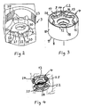
- a face milling tool 1 according to an embodiment of the invention is shown in Fig. 1 .
- the tool comprises a tool body 2 having six seats or pockets 3 each receiving a double-sided cutting insert 4 releasably fixed to the pocket.
- the cutting insert is removed from one of the pockets in Fig. 1 for illustrating the structure of the pockets.
- the tool body 2 includes a front end 5 and a rear end 6 between which a central rotation axis C1 extends around which the tool is rotatable in a direction of rotation R.
- the pockets 3 are formed in a transition between the front end and an envelope surface 7 extending between the front end and the rear end of the tool body.
- Fig. 3 shows a cutting insert 4 according to an embodiment of the invention.
- the cutting insert is double-sided or reversible, which means that the top and bottom thereof have the same design, but the side shown with the orientation of the insert in the figure as the upper side will hereinafter be called the top, although it may just as well be the bottom or lower side of the insert.
- the insert has as seen in the figures a hidden lower surface 8, a top surface 9 and a surrounding side surface 10 connecting the lower surface and the top surface.
- the lower surface and the top surface are circular and have each a circular cutting edge 11, 12 formed between these surfaces and the side surface 10.
- the first projecting member 25 is here directed at "six o'clock" with respect to the central rotation axis C1 of the tool which means in the direction of that axis, which means that it will provide support by the support face portion 27 thereon in the region of the insert configured to be exerted to a maximum load in an active chip-removing state of the tool and by that efficiently counteract any cracking or breaking tendency of the insert.
- the extended recess portions 15 are designed to allow said first projecting member to be designed to extend to a distance from said centre axis C2 of an insert received in the pocket being in the order of 90% of the distance from said centre axis to the side surface of the insert.
- the raised portion 20 is provided with two said projecting members and a second said projecting member 28 is configured to project into the extended recess portion 15 following upon the extended recess portion into which the first projecting member 25 is projecting as seen in the direction of a said rotational moment.
- the two projecting members are designed to project into a said extended recess portion with a clearance between delimiting walls 29 of the projecting member and the recess border walls 26 in the respective extended recess portion of the insert for simplifying mounting of the insert and avoiding that the seat of the pocket will be over-determined.
- each central recess of the insert may be another than six.
- the insert may have a polygonal cross-section with a plurality of distinctive straight cutting edges along the upper and lower border thereof.
- the fastening means for securing the insert in the pocket may for instance be a clamp instead of a screw and the insert does then not need to have a central through-hole neither does the raised portion of the pocket then have to have a bore.
- the insert may be single-sided. Although the extended recess portions of the lower and the top surface are aligned with each other in the embodiment shown in the figures they may be displaced with respect to each other by any desired angle. These are only a few of possible modification within said scope of the invention.
Landscapes
- Engineering & Computer Science (AREA)
- Mechanical Engineering (AREA)
- Milling Processes (AREA)
- Knives (AREA)
Priority Applications (8)
| Application Number | Priority Date | Filing Date | Title |
|---|---|---|---|
| EP14186207.8A EP3000549B1 (de) | 2014-09-24 | 2014-09-24 | Schneidwerkzeug und Schneideinsatz für ein spanabhebendes Werkzeug |
| CN201580047212.8A CN106660148A (zh) | 2014-09-24 | 2015-09-03 | 切削刀具及去屑刀具的切削刀片 |
| KR1020177007511A KR102362021B1 (ko) | 2014-09-24 | 2015-09-03 | 칩 제거 공구용의 절삭 공구 및 절삭 인서트 |
| BR112017006055A BR112017006055A2 (pt) | 2014-09-24 | 2015-09-03 | uma ferramenta de corte e uma pastilha de corte para uma ferramenta de remoção de cavaco |
| US15/513,591 US10252355B2 (en) | 2014-09-24 | 2015-09-03 | Cutting tool and a cutting insert for chip-removing tool |
| CN202211242988.3A CN115502456B (zh) | 2014-09-24 | 2015-09-03 | 切削刀具及去屑刀具的切削刀片 |
| JP2017516456A JP6762294B2 (ja) | 2014-09-24 | 2015-09-03 | 切削工具及び切屑除去工具用切削インサート |
| PCT/EP2015/070131 WO2016045928A1 (en) | 2014-09-24 | 2015-09-03 | A cutting tool and a cutting insert for a chip-removing tool |
Applications Claiming Priority (1)
| Application Number | Priority Date | Filing Date | Title |
|---|---|---|---|
| EP14186207.8A EP3000549B1 (de) | 2014-09-24 | 2014-09-24 | Schneidwerkzeug und Schneideinsatz für ein spanabhebendes Werkzeug |
Publications (2)
| Publication Number | Publication Date |
|---|---|
| EP3000549A1 true EP3000549A1 (de) | 2016-03-30 |
| EP3000549B1 EP3000549B1 (de) | 2022-11-09 |
Family
ID=51585043
Family Applications (1)
| Application Number | Title | Priority Date | Filing Date |
|---|---|---|---|
| EP14186207.8A Active EP3000549B1 (de) | 2014-09-24 | 2014-09-24 | Schneidwerkzeug und Schneideinsatz für ein spanabhebendes Werkzeug |
Country Status (7)
| Country | Link |
|---|---|
| US (1) | US10252355B2 (de) |
| EP (1) | EP3000549B1 (de) |
| JP (1) | JP6762294B2 (de) |
| KR (1) | KR102362021B1 (de) |
| CN (2) | CN106660148A (de) |
| BR (1) | BR112017006055A2 (de) |
| WO (1) | WO2016045928A1 (de) |
Cited By (1)
| Publication number | Priority date | Publication date | Assignee | Title |
|---|---|---|---|---|
| CN110114177A (zh) * | 2017-01-18 | 2019-08-09 | 山特维克知识产权股份有限公司 | 用于铣削刀具的可转位切削刀片 |
Families Citing this family (6)
| Publication number | Priority date | Publication date | Assignee | Title |
|---|---|---|---|---|
| US10646927B2 (en) * | 2018-02-19 | 2020-05-12 | Iscar, Ltd. | Round double-sided cutting insert having a peripheral surface provided with protruding indexing latches, insert holder therefor and cutting tool |
| EP3560644B1 (de) | 2018-04-27 | 2022-10-05 | Seco Tools Ab | Werkzeugkörper und fräswerkzeug |
| JP7012948B1 (ja) * | 2021-03-10 | 2022-01-31 | 株式会社タンガロイ | 刃先交換式切削工具の工具本体 |
| US12544841B2 (en) | 2021-04-26 | 2026-02-10 | Kennametal Inc. | Cutting tool comprising toolholder and round cutting insert and method for repositioning the round cutting insert in a pocket of the toolholder |
| US11786982B2 (en) | 2021-04-26 | 2023-10-17 | Kennametal Inc. | Cutting tool comprising toolholder and round cutting insert and method for repositioning the round cutting insert in a pocket of the toolholder |
| CN113275635B (zh) * | 2021-05-21 | 2022-10-11 | 株洲华锐精密工具股份有限公司 | 一种切削刀具 |
Citations (8)
| Publication number | Priority date | Publication date | Assignee | Title |
|---|---|---|---|---|
| WO1996018473A1 (en) * | 1994-12-15 | 1996-06-20 | Sandvik Ab | Milling cutter body and a method for its production |
| WO2001087523A1 (en) * | 2000-05-18 | 2001-11-22 | Sandvik Aktiebolag | Tool coupling |
| US20110103905A1 (en) * | 2009-11-03 | 2011-05-05 | Kennametal Inc. | Round Cutting Insert With Anti-Rotation Feature |
| DE102012004180A1 (de) * | 2011-03-28 | 2012-10-04 | Kennametal Inc. | Runder Schneideinsatz mit Rückdrehsicherung |
| EP1629917B1 (de) | 2004-08-30 | 2012-12-12 | Sandvik Intellectual Property AB | Schneideinsatz-Aufnahme |
| EP2617505A1 (de) * | 2012-01-20 | 2013-07-24 | Sandvik Intellectual Property AB | Locherzeugungswerkzeug |
| US20130279994A1 (en) * | 2012-04-24 | 2013-10-24 | Kennametal Inc. | Indexable circular cutting insert |
| EP2764939A1 (de) | 2011-10-07 | 2014-08-13 | Tungaloy Corporation | Schneidewerkzeug mit austauschbarer klingenkante |
Family Cites Families (17)
| Publication number | Priority date | Publication date | Assignee | Title |
|---|---|---|---|---|
| US3662444A (en) * | 1970-03-09 | 1972-05-16 | Ingersoll Milling Machine Co | Indexable cutting insert and holder therefor |
| JP2003117717A (ja) * | 2000-10-27 | 2003-04-23 | Sumitomo Electric Ind Ltd | ワイパーチップおよび回転切削工具用ワイパーチップ |
| SE525913C2 (sv) * | 2002-12-20 | 2005-05-24 | Seco Tools Ab | Skär, verktyg samt metod för montering av skär där skäret kan orienteras i önskad position |
| DE10338276B4 (de) * | 2003-08-15 | 2008-05-21 | NUBIUS GROUP Präzisionswerkzeuge GmbH | Fräswerkzeug |
| SE530181C2 (sv) * | 2005-12-21 | 2008-03-18 | Sandvik Intellectual Property | Verktyg för spånavskiljande bearbetning samt grundkropp och separat låsorgan härför |
| IL182343A0 (en) * | 2007-04-01 | 2007-07-24 | Iscar Ltd | Cutting insert and tool for milling and ramping at high feed rates |
| SE531502C2 (sv) * | 2007-06-05 | 2009-04-28 | Sandvik Intellectual Property | Verktyg för spånavskiljande bearbetning samt grundkropp och indexerbart skär härför |
| KR101549718B1 (ko) * | 2008-06-26 | 2015-09-02 | 쎄코 툴스 에이비 | 절삭 인서트, 밀링 절삭 공구, 및 절삭 인서트군 |
| AT11470U1 (de) * | 2009-06-10 | 2010-11-15 | Ceratizit Austria Gmbh | Schneidwerkzeug |
| JP5754331B2 (ja) * | 2011-09-30 | 2015-07-29 | 三菱日立ツール株式会社 | 刃先交換式切削工具 |
| SE536344C2 (sv) * | 2012-01-30 | 2013-09-03 | Sandvik Intellectual Property | Fräsverktyg jämte frässkär där skäreggen har spetsig stigningsvinkel |
| US20130330136A1 (en) * | 2012-06-06 | 2013-12-12 | Iscar, Ltd. | Cutting Insert and Tool Having an Anti-Slip Arrangement |
| US9283626B2 (en) * | 2012-09-25 | 2016-03-15 | Kennametal Inc. | Double-sided cutting inserts with anti-rotation features |
| US9011049B2 (en) * | 2012-09-25 | 2015-04-21 | Kennametal Inc. | Double-sided cutting inserts with anti-rotation features |
| EP3162481B1 (de) * | 2014-06-24 | 2022-12-21 | Sumitomo Electric Hardmetal Corp. | Schneidwerkzeug und werkzeugkörper |
| US10406608B2 (en) * | 2015-01-19 | 2019-09-10 | Kennametal Inc. | Cutting insert and pocket with uninterrupted and continuous seating surface perimeter |
| US10363616B2 (en) * | 2015-02-19 | 2019-07-30 | Tungaloy Corporation | Tool body, insert support mechanism and cutting tool |
-
2014
- 2014-09-24 EP EP14186207.8A patent/EP3000549B1/de active Active
-
2015
- 2015-09-03 JP JP2017516456A patent/JP6762294B2/ja active Active
- 2015-09-03 US US15/513,591 patent/US10252355B2/en active Active
- 2015-09-03 CN CN201580047212.8A patent/CN106660148A/zh active Pending
- 2015-09-03 KR KR1020177007511A patent/KR102362021B1/ko active Active
- 2015-09-03 BR BR112017006055A patent/BR112017006055A2/pt not_active Application Discontinuation
- 2015-09-03 CN CN202211242988.3A patent/CN115502456B/zh active Active
- 2015-09-03 WO PCT/EP2015/070131 patent/WO2016045928A1/en not_active Ceased
Patent Citations (8)
| Publication number | Priority date | Publication date | Assignee | Title |
|---|---|---|---|---|
| WO1996018473A1 (en) * | 1994-12-15 | 1996-06-20 | Sandvik Ab | Milling cutter body and a method for its production |
| WO2001087523A1 (en) * | 2000-05-18 | 2001-11-22 | Sandvik Aktiebolag | Tool coupling |
| EP1629917B1 (de) | 2004-08-30 | 2012-12-12 | Sandvik Intellectual Property AB | Schneideinsatz-Aufnahme |
| US20110103905A1 (en) * | 2009-11-03 | 2011-05-05 | Kennametal Inc. | Round Cutting Insert With Anti-Rotation Feature |
| DE102012004180A1 (de) * | 2011-03-28 | 2012-10-04 | Kennametal Inc. | Runder Schneideinsatz mit Rückdrehsicherung |
| EP2764939A1 (de) | 2011-10-07 | 2014-08-13 | Tungaloy Corporation | Schneidewerkzeug mit austauschbarer klingenkante |
| EP2617505A1 (de) * | 2012-01-20 | 2013-07-24 | Sandvik Intellectual Property AB | Locherzeugungswerkzeug |
| US20130279994A1 (en) * | 2012-04-24 | 2013-10-24 | Kennametal Inc. | Indexable circular cutting insert |
Cited By (2)
| Publication number | Priority date | Publication date | Assignee | Title |
|---|---|---|---|---|
| CN110114177A (zh) * | 2017-01-18 | 2019-08-09 | 山特维克知识产权股份有限公司 | 用于铣削刀具的可转位切削刀片 |
| CN110114177B (zh) * | 2017-01-18 | 2021-02-09 | 山特维克知识产权股份有限公司 | 用于铣削刀具的可转位切削刀片 |
Also Published As
| Publication number | Publication date |
|---|---|
| JP6762294B2 (ja) | 2020-09-30 |
| EP3000549B1 (de) | 2022-11-09 |
| JP2017528330A (ja) | 2017-09-28 |
| KR102362021B1 (ko) | 2022-02-10 |
| CN115502456A (zh) | 2022-12-23 |
| BR112017006055A2 (pt) | 2017-12-19 |
| CN115502456B (zh) | 2026-03-17 |
| US20170291233A1 (en) | 2017-10-12 |
| WO2016045928A1 (en) | 2016-03-31 |
| US10252355B2 (en) | 2019-04-09 |
| CN106660148A (zh) | 2017-05-10 |
| KR20170058373A (ko) | 2017-05-26 |
Similar Documents
| Publication | Publication Date | Title |
|---|---|---|
| US10252355B2 (en) | Cutting tool and a cutting insert for chip-removing tool | |
| EP3199284B1 (de) | Wendeschneidplatte für einen schaftfräser und mit solch einer schneidplatte ausgestatteter schaftfräser | |
| CN110497006B (zh) | 切削刀片以及切削工具 | |
| US10406608B2 (en) | Cutting insert and pocket with uninterrupted and continuous seating surface perimeter | |
| US9776258B2 (en) | Double-sided, trigon cutting insert with rounded minor cutting edge and cutting tool therefor | |
| KR20170086513A (ko) | 스퀘어 숄더 밀링용 절삭 인서트 및 절삭 공구 | |
| EP3924128B1 (de) | Rotationsschneidkörper mit einsatztasche mit sitzfläche mit einer vielzahl von anschlagelementen, drehschneidwerkzeug und einsatz | |
| US11229960B2 (en) | Cutting insert and shoulder milling tool | |
| US10406609B2 (en) | Single-sided four-way indexable positive cutting insert and insert mill therefor | |
| EP3351329A1 (de) | Indexierbarer schneideeinsatz für ein fräswerkzeug | |
| EP2730360A1 (de) | Schneideeinsatz und schneidewerkzeug | |
| US7357603B2 (en) | Toolholder and cutting insert used therein | |
| US8540462B2 (en) | Shim plate for tools for cutting machining as well as a tool | |
| JPH039935Y2 (de) | ||
| US10906107B2 (en) | Single-sided four-way indexable positive cutting insert and insert mill therefor | |
| KR20060135212A (ko) | 절삭 인서트 | |
| IL274244B1 (en) | One-sided cutting application, positive and indexable in four directions and milling for it |
Legal Events
| Date | Code | Title | Description |
|---|---|---|---|
| PUAI | Public reference made under article 153(3) epc to a published international application that has entered the european phase |
Free format text: ORIGINAL CODE: 0009012 |
|
| AK | Designated contracting states |
Kind code of ref document: A1 Designated state(s): AL AT BE BG CH CY CZ DE DK EE ES FI FR GB GR HR HU IE IS IT LI LT LU LV MC MK MT NL NO PL PT RO RS SE SI SK SM TR |
|
| AX | Request for extension of the european patent |
Extension state: BA ME |
|
| 17P | Request for examination filed |
Effective date: 20160930 |
|
| RBV | Designated contracting states (corrected) |
Designated state(s): AL AT BE BG CH CY CZ DE DK EE ES FI FR GB GR HR HU IE IS IT LI LT LU LV MC MK MT NL NO PL PT RO RS SE SI SK SM TR |
|
| STAA | Information on the status of an ep patent application or granted ep patent |
Free format text: STATUS: EXAMINATION IS IN PROGRESS |
|
| 17Q | First examination report despatched |
Effective date: 20190605 |
|
| GRAP | Despatch of communication of intention to grant a patent |
Free format text: ORIGINAL CODE: EPIDOSNIGR1 |
|
| STAA | Information on the status of an ep patent application or granted ep patent |
Free format text: STATUS: GRANT OF PATENT IS INTENDED |
|
| INTG | Intention to grant announced |
Effective date: 20220504 |
|
| RIN1 | Information on inventor provided before grant (corrected) |
Inventor name: MARIE, GILLES Inventor name: RUE, MARC Inventor name: GASTHUYS, JACQUES |
|
| GRAS | Grant fee paid |
Free format text: ORIGINAL CODE: EPIDOSNIGR3 |
|
| GRAA | (expected) grant |
Free format text: ORIGINAL CODE: 0009210 |
|
| STAA | Information on the status of an ep patent application or granted ep patent |
Free format text: STATUS: THE PATENT HAS BEEN GRANTED |
|
| AK | Designated contracting states |
Kind code of ref document: B1 Designated state(s): AL AT BE BG CH CY CZ DE DK EE ES FI FR GB GR HR HU IE IS IT LI LT LU LV MC MK MT NL NO PL PT RO RS SE SI SK SM TR |
|
| REG | Reference to a national code |
Ref country code: GB Ref legal event code: FG4D |
|
| REG | Reference to a national code |
Ref country code: CH Ref legal event code: EP Ref country code: AT Ref legal event code: REF Ref document number: 1530033 Country of ref document: AT Kind code of ref document: T Effective date: 20221115 |
|
| REG | Reference to a national code |
Ref country code: DE Ref legal event code: R096 Ref document number: 602014085465 Country of ref document: DE |
|
| REG | Reference to a national code |
Ref country code: IE Ref legal event code: FG4D |
|
| REG | Reference to a national code |
Ref country code: LT Ref legal event code: MG9D |
|
| REG | Reference to a national code |
Ref country code: NL Ref legal event code: MP Effective date: 20221109 |
|
| REG | Reference to a national code |
Ref country code: AT Ref legal event code: MK05 Ref document number: 1530033 Country of ref document: AT Kind code of ref document: T Effective date: 20221109 |
|
| PG25 | Lapsed in a contracting state [announced via postgrant information from national office to epo] |
Ref country code: SE Free format text: LAPSE BECAUSE OF FAILURE TO SUBMIT A TRANSLATION OF THE DESCRIPTION OR TO PAY THE FEE WITHIN THE PRESCRIBED TIME-LIMIT Effective date: 20221109 Ref country code: PT Free format text: LAPSE BECAUSE OF FAILURE TO SUBMIT A TRANSLATION OF THE DESCRIPTION OR TO PAY THE FEE WITHIN THE PRESCRIBED TIME-LIMIT Effective date: 20230309 Ref country code: NO Free format text: LAPSE BECAUSE OF FAILURE TO SUBMIT A TRANSLATION OF THE DESCRIPTION OR TO PAY THE FEE WITHIN THE PRESCRIBED TIME-LIMIT Effective date: 20230209 Ref country code: LT Free format text: LAPSE BECAUSE OF FAILURE TO SUBMIT A TRANSLATION OF THE DESCRIPTION OR TO PAY THE FEE WITHIN THE PRESCRIBED TIME-LIMIT Effective date: 20221109 Ref country code: FI Free format text: LAPSE BECAUSE OF FAILURE TO SUBMIT A TRANSLATION OF THE DESCRIPTION OR TO PAY THE FEE WITHIN THE PRESCRIBED TIME-LIMIT Effective date: 20221109 Ref country code: ES Free format text: LAPSE BECAUSE OF FAILURE TO SUBMIT A TRANSLATION OF THE DESCRIPTION OR TO PAY THE FEE WITHIN THE PRESCRIBED TIME-LIMIT Effective date: 20221109 Ref country code: AT Free format text: LAPSE BECAUSE OF FAILURE TO SUBMIT A TRANSLATION OF THE DESCRIPTION OR TO PAY THE FEE WITHIN THE PRESCRIBED TIME-LIMIT Effective date: 20221109 |
|
| PG25 | Lapsed in a contracting state [announced via postgrant information from national office to epo] |
Ref country code: RS Free format text: LAPSE BECAUSE OF FAILURE TO SUBMIT A TRANSLATION OF THE DESCRIPTION OR TO PAY THE FEE WITHIN THE PRESCRIBED TIME-LIMIT Effective date: 20221109 Ref country code: PL Free format text: LAPSE BECAUSE OF FAILURE TO SUBMIT A TRANSLATION OF THE DESCRIPTION OR TO PAY THE FEE WITHIN THE PRESCRIBED TIME-LIMIT Effective date: 20221109 Ref country code: LV Free format text: LAPSE BECAUSE OF FAILURE TO SUBMIT A TRANSLATION OF THE DESCRIPTION OR TO PAY THE FEE WITHIN THE PRESCRIBED TIME-LIMIT Effective date: 20221109 Ref country code: IS Free format text: LAPSE BECAUSE OF FAILURE TO SUBMIT A TRANSLATION OF THE DESCRIPTION OR TO PAY THE FEE WITHIN THE PRESCRIBED TIME-LIMIT Effective date: 20230309 Ref country code: HR Free format text: LAPSE BECAUSE OF FAILURE TO SUBMIT A TRANSLATION OF THE DESCRIPTION OR TO PAY THE FEE WITHIN THE PRESCRIBED TIME-LIMIT Effective date: 20221109 Ref country code: GR Free format text: LAPSE BECAUSE OF FAILURE TO SUBMIT A TRANSLATION OF THE DESCRIPTION OR TO PAY THE FEE WITHIN THE PRESCRIBED TIME-LIMIT Effective date: 20230210 |
|
| PG25 | Lapsed in a contracting state [announced via postgrant information from national office to epo] |
Ref country code: NL Free format text: LAPSE BECAUSE OF FAILURE TO SUBMIT A TRANSLATION OF THE DESCRIPTION OR TO PAY THE FEE WITHIN THE PRESCRIBED TIME-LIMIT Effective date: 20221109 |
|
| P01 | Opt-out of the competence of the unified patent court (upc) registered |
Effective date: 20230603 |
|
| PG25 | Lapsed in a contracting state [announced via postgrant information from national office to epo] |
Ref country code: SM Free format text: LAPSE BECAUSE OF FAILURE TO SUBMIT A TRANSLATION OF THE DESCRIPTION OR TO PAY THE FEE WITHIN THE PRESCRIBED TIME-LIMIT Effective date: 20221109 Ref country code: RO Free format text: LAPSE BECAUSE OF FAILURE TO SUBMIT A TRANSLATION OF THE DESCRIPTION OR TO PAY THE FEE WITHIN THE PRESCRIBED TIME-LIMIT Effective date: 20221109 Ref country code: EE Free format text: LAPSE BECAUSE OF FAILURE TO SUBMIT A TRANSLATION OF THE DESCRIPTION OR TO PAY THE FEE WITHIN THE PRESCRIBED TIME-LIMIT Effective date: 20221109 Ref country code: DK Free format text: LAPSE BECAUSE OF FAILURE TO SUBMIT A TRANSLATION OF THE DESCRIPTION OR TO PAY THE FEE WITHIN THE PRESCRIBED TIME-LIMIT Effective date: 20221109 Ref country code: CZ Free format text: LAPSE BECAUSE OF FAILURE TO SUBMIT A TRANSLATION OF THE DESCRIPTION OR TO PAY THE FEE WITHIN THE PRESCRIBED TIME-LIMIT Effective date: 20221109 |
|
| REG | Reference to a national code |
Ref country code: DE Ref legal event code: R097 Ref document number: 602014085465 Country of ref document: DE |
|
| PG25 | Lapsed in a contracting state [announced via postgrant information from national office to epo] |
Ref country code: SK Free format text: LAPSE BECAUSE OF FAILURE TO SUBMIT A TRANSLATION OF THE DESCRIPTION OR TO PAY THE FEE WITHIN THE PRESCRIBED TIME-LIMIT Effective date: 20221109 Ref country code: AL Free format text: LAPSE BECAUSE OF FAILURE TO SUBMIT A TRANSLATION OF THE DESCRIPTION OR TO PAY THE FEE WITHIN THE PRESCRIBED TIME-LIMIT Effective date: 20221109 |
|
| PLBE | No opposition filed within time limit |
Free format text: ORIGINAL CODE: 0009261 |
|
| STAA | Information on the status of an ep patent application or granted ep patent |
Free format text: STATUS: NO OPPOSITION FILED WITHIN TIME LIMIT |
|
| 26N | No opposition filed |
Effective date: 20230810 |
|
| PG25 | Lapsed in a contracting state [announced via postgrant information from national office to epo] |
Ref country code: SI Free format text: LAPSE BECAUSE OF FAILURE TO SUBMIT A TRANSLATION OF THE DESCRIPTION OR TO PAY THE FEE WITHIN THE PRESCRIBED TIME-LIMIT Effective date: 20221109 |
|
| REG | Reference to a national code |
Ref country code: CH Ref legal event code: PL |
|
| PG25 | Lapsed in a contracting state [announced via postgrant information from national office to epo] |
Ref country code: LU Free format text: LAPSE BECAUSE OF NON-PAYMENT OF DUE FEES Effective date: 20230924 |
|
| REG | Reference to a national code |
Ref country code: BE Ref legal event code: MM Effective date: 20230930 |
|
| PG25 | Lapsed in a contracting state [announced via postgrant information from national office to epo] |
Ref country code: LU Free format text: LAPSE BECAUSE OF NON-PAYMENT OF DUE FEES Effective date: 20230924 Ref country code: MC Free format text: LAPSE BECAUSE OF FAILURE TO SUBMIT A TRANSLATION OF THE DESCRIPTION OR TO PAY THE FEE WITHIN THE PRESCRIBED TIME-LIMIT Effective date: 20221109 |
|
| REG | Reference to a national code |
Ref country code: IE Ref legal event code: MM4A |
|
| PG25 | Lapsed in a contracting state [announced via postgrant information from national office to epo] |
Ref country code: IE Free format text: LAPSE BECAUSE OF NON-PAYMENT OF DUE FEES Effective date: 20230924 |
|
| PG25 | Lapsed in a contracting state [announced via postgrant information from national office to epo] |
Ref country code: CH Free format text: LAPSE BECAUSE OF NON-PAYMENT OF DUE FEES Effective date: 20230930 |
|
| PG25 | Lapsed in a contracting state [announced via postgrant information from national office to epo] |
Ref country code: IE Free format text: LAPSE BECAUSE OF NON-PAYMENT OF DUE FEES Effective date: 20230924 Ref country code: CH Free format text: LAPSE BECAUSE OF NON-PAYMENT OF DUE FEES Effective date: 20230930 |
|
| PG25 | Lapsed in a contracting state [announced via postgrant information from national office to epo] |
Ref country code: BE Free format text: LAPSE BECAUSE OF NON-PAYMENT OF DUE FEES Effective date: 20230930 |
|
| PG25 | Lapsed in a contracting state [announced via postgrant information from national office to epo] |
Ref country code: BG Free format text: LAPSE BECAUSE OF FAILURE TO SUBMIT A TRANSLATION OF THE DESCRIPTION OR TO PAY THE FEE WITHIN THE PRESCRIBED TIME-LIMIT Effective date: 20221109 |
|
| PG25 | Lapsed in a contracting state [announced via postgrant information from national office to epo] |
Ref country code: BG Free format text: LAPSE BECAUSE OF FAILURE TO SUBMIT A TRANSLATION OF THE DESCRIPTION OR TO PAY THE FEE WITHIN THE PRESCRIBED TIME-LIMIT Effective date: 20221109 |
|
| PG25 | Lapsed in a contracting state [announced via postgrant information from national office to epo] |
Ref country code: CY Free format text: LAPSE BECAUSE OF FAILURE TO SUBMIT A TRANSLATION OF THE DESCRIPTION OR TO PAY THE FEE WITHIN THE PRESCRIBED TIME-LIMIT; INVALID AB INITIO Effective date: 20140924 |
|
| PG25 | Lapsed in a contracting state [announced via postgrant information from national office to epo] |
Ref country code: HU Free format text: LAPSE BECAUSE OF FAILURE TO SUBMIT A TRANSLATION OF THE DESCRIPTION OR TO PAY THE FEE WITHIN THE PRESCRIBED TIME-LIMIT; INVALID AB INITIO Effective date: 20140924 |
|
| PGFP | Annual fee paid to national office [announced via postgrant information from national office to epo] |
Ref country code: DE Payment date: 20250730 Year of fee payment: 12 |
|
| PGFP | Annual fee paid to national office [announced via postgrant information from national office to epo] |
Ref country code: IT Payment date: 20250825 Year of fee payment: 12 |
|
| PGFP | Annual fee paid to national office [announced via postgrant information from national office to epo] |
Ref country code: GB Payment date: 20250731 Year of fee payment: 12 |
|
| PGFP | Annual fee paid to national office [announced via postgrant information from national office to epo] |
Ref country code: FR Payment date: 20250821 Year of fee payment: 12 |
|
| PG25 | Lapsed in a contracting state [announced via postgrant information from national office to epo] |
Ref country code: TR Free format text: LAPSE BECAUSE OF FAILURE TO SUBMIT A TRANSLATION OF THE DESCRIPTION OR TO PAY THE FEE WITHIN THE PRESCRIBED TIME-LIMIT Effective date: 20221109 |