EP2436493B2 - Verwendung einer Vorrichtung mit Produktförderer und Querantrieb - Google Patents
Verwendung einer Vorrichtung mit Produktförderer und Querantrieb Download PDFInfo
- Publication number
- EP2436493B2 EP2436493B2 EP10011822.3A EP10011822A EP2436493B2 EP 2436493 B2 EP2436493 B2 EP 2436493B2 EP 10011822 A EP10011822 A EP 10011822A EP 2436493 B2 EP2436493 B2 EP 2436493B2
- Authority
- EP
- European Patent Office
- Prior art keywords
- product conveyor
- transverse
- accordance
- product
- conveyor
- Prior art date
- Legal status (The legal status is an assumption and is not a legal conclusion. Google has not performed a legal analysis and makes no representation as to the accuracy of the status listed.)
- Active
Links
Images


Classifications
-
- B—PERFORMING OPERATIONS; TRANSPORTING
- B26—HAND CUTTING TOOLS; CUTTING; SEVERING
- B26D—CUTTING; DETAILS COMMON TO MACHINES FOR PERFORATING, PUNCHING, CUTTING-OUT, STAMPING-OUT OR SEVERING
- B26D7/00—Details of apparatus for cutting, cutting-out, stamping-out, punching, perforating, or severing by means other than cutting
- B26D7/27—Means for performing other operations combined with cutting
- B26D7/32—Means for performing other operations combined with cutting for conveying or stacking cut product
-
- B—PERFORMING OPERATIONS; TRANSPORTING
- B65—CONVEYING; PACKING; STORING; HANDLING THIN OR FILAMENTARY MATERIAL
- B65H—HANDLING THIN OR FILAMENTARY MATERIAL, e.g. SHEETS, WEBS, CABLES
- B65H5/00—Feeding articles separated from piles; Feeding articles to machines
- B65H5/02—Feeding articles separated from piles; Feeding articles to machines by belts or chains, e.g. between belts or chains
- B65H5/021—Feeding articles separated from piles; Feeding articles to machines by belts or chains, e.g. between belts or chains by belts
-
- F—MECHANICAL ENGINEERING; LIGHTING; HEATING; WEAPONS; BLASTING
- F16—ENGINEERING ELEMENTS AND UNITS; GENERAL MEASURES FOR PRODUCING AND MAINTAINING EFFECTIVE FUNCTIONING OF MACHINES OR INSTALLATIONS; THERMAL INSULATION IN GENERAL
- F16F—SPRINGS; SHOCK-ABSORBERS; MEANS FOR DAMPING VIBRATION
- F16F15/00—Suppression of vibrations in systems; Means or arrangements for avoiding or reducing out-of-balance forces, e.g. due to motion
- F16F15/22—Compensation of inertia forces
-
- B—PERFORMING OPERATIONS; TRANSPORTING
- B26—HAND CUTTING TOOLS; CUTTING; SEVERING
- B26D—CUTTING; DETAILS COMMON TO MACHINES FOR PERFORATING, PUNCHING, CUTTING-OUT, STAMPING-OUT OR SEVERING
- B26D7/00—Details of apparatus for cutting, cutting-out, stamping-out, punching, perforating, or severing by means other than cutting
-
- B—PERFORMING OPERATIONS; TRANSPORTING
- B65—CONVEYING; PACKING; STORING; HANDLING THIN OR FILAMENTARY MATERIAL
- B65H—HANDLING THIN OR FILAMENTARY MATERIAL, e.g. SHEETS, WEBS, CABLES
- B65H2301/00—Handling processes for sheets or webs
- B65H2301/30—Orientation, displacement, position of the handled material
- B65H2301/34—Modifying, selecting, changing direction of displacement
- B65H2301/341—Modifying, selecting, changing direction of displacement without change of plane of displacement
- B65H2301/3411—Right angle arrangement, i.e. 90 degrees
-
- B—PERFORMING OPERATIONS; TRANSPORTING
- B65—CONVEYING; PACKING; STORING; HANDLING THIN OR FILAMENTARY MATERIAL
- B65H—HANDLING THIN OR FILAMENTARY MATERIAL, e.g. SHEETS, WEBS, CABLES
- B65H2404/00—Parts for transporting or guiding the handled material
- B65H2404/20—Belts
- B65H2404/26—Particular arrangement of belt, or belts
- B65H2404/264—Arrangement of side-by-side belts
- B65H2404/2641—Arrangement of side-by-side belts on movable frame
-
- Y—GENERAL TAGGING OF NEW TECHNOLOGICAL DEVELOPMENTS; GENERAL TAGGING OF CROSS-SECTIONAL TECHNOLOGIES SPANNING OVER SEVERAL SECTIONS OF THE IPC; TECHNICAL SUBJECTS COVERED BY FORMER USPC CROSS-REFERENCE ART COLLECTIONS [XRACs] AND DIGESTS
- Y10—TECHNICAL SUBJECTS COVERED BY FORMER USPC
- Y10T—TECHNICAL SUBJECTS COVERED BY FORMER US CLASSIFICATION
- Y10T74/00—Machine element or mechanism
- Y10T74/18—Mechanical movements
- Y10T74/1836—Rotary to rotary
- Y10T74/18368—Inertia or centrifugal transmitters
Definitions
- the present invention relates to a use of a device having a product conveyor which can be driven in a conveying direction and a transverse drive, by means of which the product conveyor can be moved in a direction transverse to the conveying direction.
- Such a use is basically from US 2003/0145700 A1 and is used, for example, in conjunction with a slicer for slicing food products to enable a shingled arrangement, so-called "shingling," of product slices which are separated from a food product by the slicer.
- the preamble of claim 1 is based on this document.
- the invention has for its object to provide a use of a device of the type mentioned, which overcomes the problem of unwanted, caused by the transverse movement of the product conveyor vibrations.
- the balancing mass forms a counterweight to the product conveyor, compensated by which caused by the transverse movement of the product conveyor forces and resulting vibrations in the device are at least almost completely prevented.
- the smooth running of the device is increased by the coupling of product conveyor and leveling compound.
- the equipment of the device with an additional, specifically provided for this purpose balancing mass thus makes it possible to realize even in smaller devices safely faster transverse movements and / or transverse movements with a larger amplitude. Accordingly, the amplitude and / or frequency of the transverse movement of the product conveyor can be increased even in larger devices.
- transverse movement and “transverse direction” in this context are meant all movements or directions which are not parallel to the conveying direction, i. So at an angle greater than 0 ° to the conveying direction.
- the balancing mass is movable, in particular displaceable, mounted.
- the balancing mass is preferably coupled by a coupling mechanism with the product conveyor such that a transverse movement of the product conveyor leads to a, in particular synchronous, movement of the balancing mass in the opposite direction to the product conveyor.
- the balancing mass is moved in such a manner opposite to the product conveyor that the forces resulting from the transverse movement of the product conveyor on the one hand and the forces caused by the correspondingly inverse movement of the balancing mass cancel each other out at least to a large extent. Consequently, there are no forces that could cause the device to vibrate as a whole.
- the coupling mechanism comprises a two-sided lever, one end of which is connected to the balancing mass and the other end is connected to the transverse drive.
- the transverse drive not only provides for the transverse movement of the product conveyor, but at the same time for the movement of the balancing mass.
- a lever mechanism is a particularly simple mechanism for moving the balancing mass.
- the lever is preferably pivotable about an axis which is oriented at right angles to the transverse direction of movement of the product conveyor and / or to the direction of movement of the balancing mass
- the lever is articulated in the region of its one end with the balancing mass.
- the lever is preferably pivotally connected to a spindle nut receptacle or a threaded nut, which is in engagement with a threaded spindle of the transverse drive.
- the threaded nut may be fixedly connected to a part of a support structure of the product conveyor, which is displaceable in the direction of the transverse movement relative to a fixed part of the support structure.
- the displaceable part of the support structure can thereby form a back and forth movable support arm for the product conveyor.
- the product conveyor may be attached to one of the balancing mass end facing away from the support arm thereto.
- the balancing mass is formed so that the center of gravity of the balancing mass and the center of gravity of the displaceable part of the support structure lie on an axis which is substantially extends in the direction of the transverse movement. This ensures that the forces resulting from the opposite transverse movements of product conveyor and leveling compound are at least approximately aligned coaxially. Undesirable torques that could occur as a result of mutually offset forces acting are thus avoided, which ultimately contributes to even smoother running of the device.
- the balancing mass can surround the stationary part of the support structure for this purpose, for example in the circumferential direction, at least in sections.
- the balancing mass and the product conveyor for optimal force compensation are preferably moved by equal amounts in the transverse direction.
- the mass of the balancing mass may also be smaller than the mass of the product conveyor, in which case the balancing mass would have to cover a further path in the transverse direction for optimal force compensation than the product conveyor.
- the balance mass would need to be traversed by a smaller amount in the transverse direction for optimal force compensation.
- caused by the transverse movement of the product conveyor forces are compensated only partially by the balancing mass, for example, when a balancing mass with a mass that is less than the mass of the product conveyor, not a sufficiently large way in Transverse direction is moved, eg only as far as the product conveyor or less.
- the forces caused by the transverse movement of the product conveyor would be partially absorbed by a basic structure of the device, which in turn would have to have sufficient mass to prevent at least approximately completely resulting vibrations in the device resulting from the transverse movement of the product conveyor.
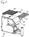
- Shown in the figures is a conveyor downstream of a slicer for slicing food products to remove product slices which are separated from a food product by the slicer.
- the apparatus comprises a basic structure 10, a product conveyor 12 and a drive housed in a drive housing 14 for the product conveyor 12.
- the product conveyor 12 are seen in the conveying direction, two further conveyors 16, 18 downstream.
- conveyor belts 62 of the product conveyor 12 are moved in the conveying direction during the cutting process.
- the product conveyor 12 is additionally moved in a direction transverse to the conveying direction.
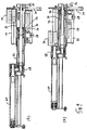
- Fig. 2a is the product conveyor 12 in a transversely maximum retracted position and in Fig. 2b shown in a maximum extended position.
- the product conveyor 12 is reciprocated at a speed adapted to the cutting speed of the cutting machine between a retracted position and an extended position.
- the product conveyor 12 is coupled to an accommodated in the drive housing 14 balancing mass 20 in such a way that the balancing mass 20 always moves in the direction opposite to the product conveyor 12 direction.
- the balancing mass 20 resulting forces are compensated from the transverse movement of the product conveyor 12, which could otherwise cause undesirable vibrations in the device.
- the transverse movement of the product conveyor 12 and balancing mass 20 takes place by means of a transverse drive motor 22 housed in the drive housing 14 (FIG. Fig. 4 . 6 and 7 ), which drives a threaded spindle 26 via a drive belt 24.
- the threaded spindle 26 is in engagement with a spindle nut, not shown, which, viewed in the transverse direction, moves back and forth, depending on the direction of rotation of the threaded spindle 26.
- the spindle nut is housed in a spindle nut receptacle 28, which is mounted on a guide rod 30 displaceable in the transverse direction.
- the spindle nut receptacle 28 is fixedly connected to a tubular support arm 32, which has a protruding from the drive housing 14 end, in the region of the product conveyor 12 is mounted.
- the product conveyor 12 is supported by the support arm 32.
- the support arm 32 is slidably mounted in a arranged in the drive housing 14 fixed support tube 34 in the transverse direction. So that the spindle nut receptacle 28 can engage the support arm 32 mounted in the support tube 34, the support tube 34 has a longitudinal opening 36 extending in the axial direction.
- the spindle nut receptacle 28 is moved in the transverse direction and thereby the support arm 32 and thus ultimately the product conveyor 12 is moved in the transverse direction.
- the spindle nut receptacle 28 is pivotally connected at its bottom to one end 38 of a two-sided lever 40 which is rotatably mounted about an axis perpendicular to the transverse direction axis, in the present embodiment, vertical axis 42.
- the other end 44 of the lever 40 is pivotally connected to the balancing mass 20 which is slidably mounted on two guide rods 46, 48 in the transverse direction.
- the balancing mass 20 has a transversely extending recess 50, which gives the balancing mass 20 has an approximately U-shaped cross-section.
- the profile of the recess 50 is chosen slightly larger than the profile of the support tube 34, which allows the balancing mass 20 to be arranged around the support tube 34 such that the center of gravity of the balancing mass 20 and the center of gravity of the support arm 32 lie on an axis which is at least runs approximately in the transverse direction.
- a conveyor drive motor 52 is also accommodated in the drive housing 14 (FIG. Fig. 6 ), which serves to drive the product conveyor 12 in the conveying direction.
- the conveyor drive motor 52 drives via a drive belt 54 a running in the support tube 34 drive shaft 56 whose torque is transmitted via the support arm 32 and provided at the end of the support arm 32 offset gear 58 to a drive roller 60 of the product conveyor 12 ( Fig. 8 and 9 ).
- the product conveyor 12 may also have conveyor belts or a conveyor belt extending over the substantially entire width of the product conveyor 12 instead of the strip-shaped conveyor belts 62 shown in the figures.
Landscapes
- Engineering & Computer Science (AREA)
- Mechanical Engineering (AREA)
- General Engineering & Computer Science (AREA)
- Life Sciences & Earth Sciences (AREA)
- Forests & Forestry (AREA)
- Physics & Mathematics (AREA)
- Acoustics & Sound (AREA)
- Aviation & Aerospace Engineering (AREA)
- Structure Of Belt Conveyors (AREA)
- Branching, Merging, And Special Transfer Between Conveyors (AREA)
Description
- Die vorliegende Erfindung betrifft eine Verwendung einer Vorrichtung mit einem in einer Förderrichtung antreibbaren Produktförderer und einem Querantrieb, durch den der Produktförderer in einer Richtung quer zur Förderrichtung bewegbar ist.
- Eine derartige Verwendung ist grundsätzlich aus der
US 2003/0145700 A1 bekannt und wird beispielsweise in Verbindung mit einer Schneidmaschine zum Aufschneiden von Lebensmittelprodukten eingesetzt, um eine geschindelte Anordnung, ein sogenanntes "Querschindeln", von Produktscheiben zu ermöglichen, die durch die Schneidemaschine von einem Lebensmittelprodukt abgetrennt werden. Der Oberbegriff des Anspruchs 1 basiert auf diesem Dokument. - Aufgrund der Querbewegung des Produktförderers als Ganzes treten Kräfte in der Vorrichtung auf, welche nicht nur eine entsprechend ausreichende Dimensionierung von Lagerstellen zur Lagerung des Produktförderers erfordern, sondern welche auch die Vorrichtung in ihrer Gesamtheit in unerwünschte Schwingungen versetzen kann. Das Problem unerwünschter Schwingungen ist vor allem bei kleineren Vorrichtungen ausgeprägt, deren Masse nicht ausreicht, um die durch die Querbewegung des Produktförderers verursachten Kräfte zu kompensieren, insbesondere wenn es sich um schnellere Querbewegungen handelt. Unerwünschte Schwingungen konnten in solchen Vorrichtungen bislang nur durch eine Reduzierung der Amplitude und/oder der Frequenz der Querbewegung vermieden werden.
- Der Erfindung liegt die Aufgabe zugrunde, eine Verwendung einer Vorrichtung der eingangs genannten Art zu schaffen, die das Problem unerwünschter, durch die Querbewegung des Produktförderers verursachter Schwingungen überwindet.
- Diese Aufgabe wird durch eine Verwendung gemäß Anspruch 1 gelöst.
- Die Ausgleichsmasse bildet ein Gegengewicht zu dem Produktförderer, durch welches durch die Querbewegung des Produktförderers verursachte Kräfte kompensiert und daraus resultierende Schwingungen in der Vorrichtung zumindest annähernd vollständig verhindert werden. Anders gesagt wird durch die Kopplung von Produktförderer und Ausgleichsmasse die Laufruhe der Vorrichtung erhöht. Die Ausrüstung der Vorrichtung mit einer zusätzlichen, eigens zu diesem Zweck vorgesehenen Ausgleichsmasse ermöglicht es somit, auch in kleineren Vorrichtungen gefahrlos schnellere Querbewegungen und/oder Querbewegungen mit einer größeren Amplitude zu realisieren. Entsprechend lassen sich auch in größeren Vorrichtungen die Amplitude und/oder Frequenz der Querbewegung des Produktförderers erhöhen.
- Unter "Querbewegung" und "Querrichtung" sind in diesem Kontext alle Bewegungen bzw. Richtungen zu verstehen, die nicht parallel zur Förderrichtung, d.h. also unter einem Winkel größer 0° zu der Förderrichtung verlaufen.
- Vorteilhafte Ausbildungen der Erfindung sind den Unteransprüchen, der Beschreibung und der Zeichnung zu entnehmen.
- Gemäß einer Ausführungsform ist die Ausgleichsmasse beweglich, insbesondere verschiebbar, gelagert.
- Dabei ist die Ausgleichsmasse durch einen Koppelmechanismus vorzugsweise derart mit dem Produktförderer gekoppelt, dass eine Querbewegung des Produktförderers zu einer, insbesondere synchronen, Bewegung der Ausgleichsmasse in die zum Produktförderer entgegengesetzte Richtung führt. Die Ausgleichsmasse wird mit anderen Worten also derart entgegengesetzt zu dem Produktförderer bewegt, dass sich die aus der Querbewegung des Produktförderers resultierenden Kräfte einerseits und die durch die entsprechend umgekehrte Bewegung der Ausgleichsmasse verursachten Kräfte gegenseitig zumindest weitgehend aufheben. Es treten folglich keine Kräfte auf, welche die Vorrichtung als Ganzes in Schwingung versetzen könnten.
- Gemäß einer weiteren Ausführungsform umfasst der Koppelmechanismus einen zweiseitigen Hebel, dessen eines Ende mit der Ausgleichsmasse verbunden ist und dessen anderes Ende mit dem Querantrieb verbunden ist. Der Querantrieb sorgt mit anderen Worten also nicht nur für die Querbewegung des Produktförderers, sondern gleichzeitig auch für die Bewegung der Ausgleichsmasse. Dabei stellt ein derartiger Hebelmechanismus einen besonders einfachen Mechanismus zur Bewegung der Ausgleichsmasse dar.
- Der Hebel ist bevorzugt um eine Achse verschwenkbar, die rechtwinklig zu der Querbewegungsrichtung des Produktförderers und/oder zu der Bewegungsrichtung der Ausgleichsmasse orientiert ist
- Vorteilhafterweise ist der Hebel im Bereich seines einen Endes mit der Ausgleichsmasse gelenkig verbunden. Im Bereich seines anderen Endes ist der Hebel bevorzugt mit einer Spindelmutteraufnahme oder einer Gewindemutter gelenkig verbunden, welche mit einer Gewindespindel des Querantriebs in Eingriff steht.
- Dabei kann die Gewindemutter mit einem Teil einer Trägerstruktur des Produktförderers fest verbunden sein, welcher in Richtung der Querbewegung relativ zu einem feststehenden Teil der Trägerstruktur verschiebbar ist. Der verschiebbare Teil der Trägerstruktur kann dabei einen hin und her bewegbaren Trägerarm für den Produktförderer bilden. Konkret kann der Produktförderer an einem der Ausgleichsmasse abgewandten Ende des Trägerarms an diesem angebracht sein.
- Vorteilhafterweise ist die Ausgleichsmasse so ausgebildet, dass der Schwerpunkt der Ausgleichsmasse und der Schwerpunkt des verschiebbaren Teils der Trägerstruktur auf einer Achse liegen, die sich im Wesentlichen in Richtung der Querbewegung erstreckt. Hierdurch ist sichergestellt, dass die aus den entgegengesetzten Querbewegungen von Produktförderer und Ausgleichsmasse resultierenden Kräfte zumindest annähernd koaxial ausgerichtet sind. Unerwünschte Drehmomente, die infolge zueinander versetzt wirkender Kräfte auftreten könnten, werden somit vermieden, was letztlich zu einer noch höheren Laufruhe der Vorrichtung beiträgt.
- Die Ausgleichsmasse kann den feststehenden Teil der Trägerstruktur zu diesem Zweck beispielsweise in Umfangsrichtung gesehen zumindest abschnittsweise umgeben.
- Wenn die Masse der Ausgleichsmasse und die Masse des Produktförderers gleich groß sind, werden die Ausgleichsmasse und der Produktförderer für eine optimale Kraftkompensation bevorzugt um gleiche Wegbeträge in Querrichtung bewegt. Grundsätzlich kann die Masse der Ausgleichsmasse aber auch kleiner als die Masse des Produktförderers sein, in welchem Fall die Ausgleichsmasse für eine optimale Kraftkompensation einen weiteren Weg in Querrichtung zurücklegen müsste als der Produktförderer. Umgekehrt bräuchte die Ausgleichsmasse in dem Fall, dass ihre Masse größer als die des Produktförderers ist, zur optimalen Kraftkompensation um einen geringeren Betrag in Querrichtung verfahren zu werden.
- Darüber hinaus liegt es im Rahmen der Erfindung, dass die durch die Querbewegung des Produktförderers verursachten Kräfte durch die Ausgleichsmasse nur teilweise kompensiert werden, beispielsweise wenn eine Ausgleichsmasse mit einer Masse, die geringer als die Masse des Produktförderers ist, nicht um einen ausreichend großen Weg in Querrichtung verfahren wird, z.B. nur so weit wie der Produktförderer oder weniger weit. In diesem Fall würden die durch die Querbewegung des Produktförderers verursachten Kräfte teilweise durch einen Grundaufbau der Vorrichtung aufgenommen, welcher seinerseits also eine ausreichende Masse aufweisen müsste, um aus der Querbewegung des Produktförderers resultierende Schwingungen in der Vorrichtung zumindest annähernd vollständig zu verhindern.
- Nachfolgend wird die Erfindung rein beispielhaft anhand einer vorteilhaften Ausführungsform unter Bezugnahme auf die beigefügte Zeichnung beschrieben. Es zeigen:
- Fig. 1
- eine perspektivische Ansicht einer erfindungsgemäß verwendbaren Vorrichtung mit einem Produktförderer und einem einen Antrieb für den Produktförderer beherbergenden Antriebsgehäuse;
- Fig. 2
- eine perspektivische Ansicht des Antriebsgehäuses und des Produktförderers von
Fig. 1(a) im eingefahrenen und (b) im ausgefahrenen Zustand des Produktförderers; - Fig. 3
- eine Ansicht von oben auf den Antrieb und den Produktförderer von
Fig. 1 (a) im eingefahrenen und (b) im ausgefahrenen Zustand, jeweils bei geöffnetem Antriebsgehäuse; - Fig. 4
- eine Ansicht von unten auf den Antrieb und den Produktförderer von
Fig. 1 (a) im eingefahrenen und (b) im ausgefahrenen Zustand, jeweils bei geöffnetem Antriebsgehäuse; - Fig. 5
- eine perspektivische Ansicht des Antriebsgehäuses mit geöffneter Seitenabdeckung;
- Fig. 6
- eine perspektivische Ansicht eines Förderantriebs für den Produktförderer, eines Querantriebs für den Produktförderer und einer Ausgleichsmasse;
- Fig. 7
- die Ansicht von
Fig. 6 ohne den Förderantrieb; - Fig. 8
- eine perspektivische Ansicht des Produktförderers und von Teilen seines Antriebs; und
- Fig. 9
- eine Schnittansicht der Komponenten von
Fig. 8(a) im eingefahrenen und (b) im ausgefahrenen Zustand des Produktförderers. - In den Figuren ist eine Fördervorrichtung dargestellt, die einer Schneidmaschine zum Aufschneiden von Lebensmittelprodukten nachgelagert ist, um Produktscheiben abzutransportieren, welche durch die Schneidemaschine von einem Lebensmittelprodukt abgetrennt werden.
- Wie
Fig. 1 zeigt, umfasst die Vorrichtung einen Grundaufbau 10, einen Produktförderer 12 sowie einen in einem Antriebsgehäuse 14 untergebrachten Antrieb für den Produktförderer 12. Dem Produktförderer 12 sind in Förderrichtung gesehen zwei weitere Fördereinrichtungen 16, 18 nachgelagert. - Um eine in Förderrichtung geschindelte Anordnung von durch die Schneidemaschine von einem Lebensmittelprodukt abgetrennten Produktscheiben zu ermöglichen, werden Förderbänder 62 des Produktförderers 12 während des Schneidvorgangs in Förderrichtung bewegt. Um eine quergeschindelte Anordnung der Produktscheiben zu erreichen, wird der Produktförderer 12 zusätzlich in einer Richtung quer zur Förderrichtung bewegt. In
Fig. 2a ist der Produktförderer 12 in einer in Querrichtung maximal eingefahrenen Stellung und inFig. 2b in einer maximal ausgefahrenen Stellung dargestellt. Üblicherweise wird der Produktförderer 12 mit einer an die Schneidgeschwindigkeit der Schneidemaschine angepassten Geschwindigkeit zwischen einer eingefahrenen Stellung und einer ausgefahrenen Stellung hin und her bewegt. - Wie
Fig. 3 und 4 zeigen, ist der Produktförderer 12 mit einer in dem Antriebsgehäuse 14 untergebrachten Ausgleichsmasse 20 gekoppelt und zwar derart, dass sich die Ausgleichsmasse 20 stets in die zu dem Produktförderer 12 entgegengesetzte Richtung bewegt. Durch die Ausgleichsmasse 20 werden aus der Querbewegung des Produktförderers 12 resultierende Kräfte kompensiert, welche andernfalls unerwünschte Schwingungen in der Vorrichtung verursachen könnten. - Die Querbewegung von Produktförderer 12 und Ausgleichsmasse 20 erfolgt mittels eines in dem Antriebsgehäuse 14 untergebrachten Querantriebsmotors 22 (
Fig. 4 ,6 und 7 ), welcher über einen Antriebsriemen 24 eine Gewindespindel 26 antreibt. Die Gewindespindel 26 steht mit einer nicht dargestellten Spindelmutter in Eingriff, welche sich je nach Drehrichtung der Gewindespindel 26 in Querrichtung gesehen vor und zurück bewegt. Die Spindelmutter ist in einer Spindelmutteraufnahme 28 untergebracht, die an einer Führungsstange 30 in Querrichtung verschiebbar gelagert ist. - Zur Querbewegung des Produktförderers 12 ist die Spindelmutteraufnahme 28 mit einem rohrförmigen Trägerarm 32 fest verbunden, welcher ein aus dem Antriebsgehäuse 14 hervorstehendes Ende aufweist, in dessen Bereich der Produktförderer 12 angebracht ist. Der Produktförderer 12 wird mit anderen Worten durch den Trägerarm 32 getragen.
- Der Trägerarm 32 ist in einem in dem Antriebsgehäuse 14 angeordneten feststehenden Trägerrohr 34 in Querrichtung verschiebbar gelagert. Damit die Spindelmutteraufnahme 28 an den in dem Trägerrohr 34 gelagerten Trägerarm 32 angreifen kann, weist das Trägerrohr 34 eine sich in axialer Richtung erstreckende Längsöffnung 36 auf.
- Durch eine Verdrehung der Gewindespindel 26 wird die Spindelmutteraufnahme 28 in Querrichtung verfahren und hierdurch der Trägerarm 32 und somit letztlich der Produktförderer 12 in Querrichtung bewegt.
- Wie
Fig. 4 zeigt, ist die Spindelmutteraufnahme 28 an ihrer Unterseite gelenkig mit dem einen Ende 38 eines zweiseitigen Hebels 40 verbunden, welcher um eine zur Querrichtung rechtwinklige Achse, im vorliegenden Ausführungsbeispiel vertikale Achse 42, verdrehbar gelagert ist. Das andere Ende 44 des Hebels 40 ist gelenkig mit der Ausgleichsmasse 20 verbunden, welche auf zwei Führungsstangen 46, 48 in Querrichtung verschiebbar gelagert ist. - Durch die Kopplung von Ausgleichsmasse 20 und Spindelmutteraufnahme 28 über den Hebel 40 ist sichergestellt, dass sich die Ausgleichsmasse 20 synchron mit der Spindelmutteraufnahme 28 und folglich mit dem Trägerarm 32 und dem Produktförderer 12 bewegt, und zwar stets in die entgegengesetzte Richtung.
- In
Fig. 7 ist zu erkennen, dass die Ausgleichsmasse 20 eine sich in Querrichtung erstreckende Aussparung 50 aufweist, welche der Ausgleichsmasse 20 einen etwa U-förmigen Querschnitt verleiht. Das Profil der Aussparung 50 ist etwas größer als das Profil des Trägerrohrs 34 gewählt, was es ermöglicht, die Ausgleichsmasse 20 so um das Trägerrohr 34 herum anzuordnen, dass der Schwerpunkt der Ausgleichsmasse 20 und der Schwerpunkt des Trägerarms 32 auf einer Achse liegen, die zumindest annähernd in Querrichtung verläuft. - Zusätzlich zu dem Querantriebsmotor 22 ist außerdem ein Förderantriebsmotor 52 in dem Antriebsgehäuse 14 untergebracht (
Fig. 6 ), welcher dazu dient, den Produktförderer 12 in Förderrichtung anzutreiben. Der Förderantriebsmotor 52 treibt über einen Antriebsriemen 54 eine in dem Trägerrohr 34 verlaufende Antriebswelle 56 an, deren Drehmoment über den Trägerarm 32 und ein am Ende des Trägerarms 32 vorgesehenes Versatzgetriebe 58 an eine Antriebsrolle 60 des Produktförderer 12 übertragen wird (Fig. 8 und9 ). Durch die Rotation der Antriebsrolle 60 werden um die Antriebsrolle 60 herum geführte streifenförmige Förderbänder 62 des Produktförderers 12 in Förderrichtung bewegt. - Es versteht sich, dass der Produktförderer 12 anstelle der in den Figuren gezeigten streifenförmigen Förderbänder 62 auch Förderriemen oder ein sich über die im Wesentlichen ganze Breite des Produktförderers 12 erstreckendes Förderband aufweisen kann.
-
- 12
- 10 Grundaufbau Produktförderer
- 14
- Antriebsgehäuse
- 16
- Fördereinrichtung
- 18
- Fördereinrichtung
- 20
- Ausgleichsmasse
- 22
- Antriebsmotor
- 24
- Antriebsriemen
- 26
- Gewindespindel
- 28
- Spindelmutteraufnahme
- 30
- Führungsstange
- 32
- Trägerarm
- 34
- Trägerrohr
- 36
- Längsöffnung
- 38
- Ende
- 40
- Hebel
- 42
- Achse
- 44
- Ende
- 46
- Führungsstange
- 48
- Führungsstange
- 50
- Aussparung
- 52
- Förderantriebsmotor
- 54
- Antriebsriemen
- 56
- Antriebswelle
- 58
- Versatzgetriebe
- 60
- Antriebsrolle
- 62
- Förderband
Claims (10)
- Verwendung einer Vorrichtung,
die einen in einer Förderrichtung antreibbaren Produktförderer (12) und einen Querantrieb umfasst, durch den der Produktförderer (12) als Ganzes in einer Richtung quer zur Förderrichtung bewegbar ist,
zum quergeschindelten Anordnen von durch eine Schneidemaschine von einem Lebensmittelprodukt abgetrennten Produktscheiben zusätzlich zu einem in Förderrichtung geschindelten Anordnen der Produktscheiben,
wobei der Produktförderer (12) mit einer Ausgleichsmasse (20) gekoppelt ist, mittels welcher durch eine Querbewegung des Produktförderers (12) auftretende Kräfte kompensierbar sind. - Verwendung einer Vorrichtung nach Anspruch 1,
dadurch gekennzeichnet, dass
die Ausgleichsmasse (20) beweglich, insbesondere verschiebbar, gelagert ist. - Verwendung einer Vorrichtung nach Anspruch 1 oder 2,
dadurch gekennzeichnet, dass
die Ausgleichsmasse (20) durch einen Koppelmechanismus derart mit dem Produktförderer (12) gekoppelt ist, dass eine Querbewegung des Produktförderers (12) zu einer, insbesondere synchronen, Bewegung der Ausgleichsmasse (20) in die zum Produktförderer (12) entgegengesetzte Richtung führt. - Verwendung einer Vorrichtung nach Anspruch 3,
dadurch gekennzeichnet, dass
der Koppelmechanismus einen zweiseitigen Hebel (40) umfasst, dessen eines Ende (44) mit der Ausgleichsmasse (20) verbunden ist und dessen anderes Ende (38) mit dem Querantrieb verbunden ist. - Verwendung einer Vorrichtung nach Anspruch 4,
dadurch gekennzeichnet, dass
der Hebel (40) um eine Achse (42) verschwenkbar ist, die rechtwinklig zu der Querbewegungsrichtung des Produktförderers (12) und/oder zu der Bewegungsrichtung der Ausgleichsmasse (20) orientiert ist. - Verwendung einer Vorrichtung nach Anspruch 4 oder 5,
dadurch gekennzeichnet, dass
der Hebel (40) im Bereich seines einen Endes (44) mit der Ausgleichsmasse gelenkig verbunden ist. - Verwendung einer Vorrichtung nach einem der Ansprüche 4 bis 6,
dadurch gekennzeichnet, dass
der Hebel (40) im Bereich seines anderen Endes (38) mit einer Spindelmutteraufnahme (28) oder Gewindemutter gelenkig verbunden ist, welche mit einer Gewindespindel (26) des Querantriebs in Eingriff steht. - Verwendung einer Vorrichtung nach Anspruch 7,
dadurch gekennzeichnet, dass
die Gewindemutter mit einem Teil einer Trägerstruktur für den Produktförderer (12) fest verbunden ist, welcher in Richtung der Querbewegung relativ zu einem feststehenden Teil der Trägerstruktur verschiebbar ist. - Verwendung einer Vorrichtung nach einem der vorstehenden Ansprüche,
dadurch gekennzeichnet, dass
die Ausgleichsmasse (20) so ausgebildet ist, dass der Schwerpunkt der Ausgleichsmasse (20) und der Schwerpunkt eines verschiebbaren Teils einer Trägerstruktur für den Produktförderer (12) auf einer Achse liegen, die sich im Wesentlichen in Richtung der Querbewegung erstreckt. - Verwendung einer Vorrichtung nach einem der vorstehenden Ansprüche,
dadurch gekennzeichnet, dass
die Ausgleichsmasse (20) einen feststehenden Teil einer Trägerstruktur für den Produktförderer (12) in Umfangsrichtung gesehen zumindest abschnittsweise umgibt.
Priority Applications (3)
| Application Number | Priority Date | Filing Date | Title |
|---|---|---|---|
| EP10011822.3A EP2436493B2 (de) | 2010-09-29 | 2010-09-29 | Verwendung einer Vorrichtung mit Produktförderer und Querantrieb |
| ES10011822.3T ES2444266T5 (es) | 2010-09-29 | 2010-09-29 | Uso de un dispositivo con transportador de productos y accionamiento transversal |
| US13/248,253 US8757361B2 (en) | 2010-09-29 | 2011-09-29 | Apparatus with product conveyor and transverse drive |
Applications Claiming Priority (1)
| Application Number | Priority Date | Filing Date | Title |
|---|---|---|---|
| EP10011822.3A EP2436493B2 (de) | 2010-09-29 | 2010-09-29 | Verwendung einer Vorrichtung mit Produktförderer und Querantrieb |
Publications (3)
| Publication Number | Publication Date |
|---|---|
| EP2436493A1 EP2436493A1 (de) | 2012-04-04 |
| EP2436493B1 EP2436493B1 (de) | 2014-01-01 |
| EP2436493B2 true EP2436493B2 (de) | 2017-04-05 |
Family
ID=43618289
Family Applications (1)
| Application Number | Title | Priority Date | Filing Date |
|---|---|---|---|
| EP10011822.3A Active EP2436493B2 (de) | 2010-09-29 | 2010-09-29 | Verwendung einer Vorrichtung mit Produktförderer und Querantrieb |
Country Status (3)
| Country | Link |
|---|---|
| US (1) | US8757361B2 (de) |
| EP (1) | EP2436493B2 (de) |
| ES (1) | ES2444266T5 (de) |
Families Citing this family (2)
| Publication number | Priority date | Publication date | Assignee | Title |
|---|---|---|---|---|
| CN107139421A (zh) * | 2017-06-28 | 2017-09-08 | 浙江派尔电气有限公司 | 塑料管卸载装置 |
| DE102020129751A1 (de) | 2020-11-11 | 2022-05-12 | Multivac Sepp Haggenmüller Se & Co. Kg | Aufschneide-Maschine |
Citations (1)
| Publication number | Priority date | Publication date | Assignee | Title |
|---|---|---|---|---|
| EP0820943B1 (de) † | 1996-07-24 | 2002-06-26 | Dixie-Union GmbH & Co. KG | Vorrichtung zum Verändern der Zahl der Förderströme von Lebensmittelstapeln |
Family Cites Families (9)
| Publication number | Priority date | Publication date | Assignee | Title |
|---|---|---|---|---|
| DE4319171A1 (de) | 1993-06-09 | 1994-12-15 | Dixie Union Verpackungen Gmbh | Vorrichtung zum schindelartigen Anordnen von aufgeschnittenen Gütern |
| JPH09301310A (ja) * | 1996-05-08 | 1997-11-25 | Ishida Co Ltd | 箱詰め装置 |
| JP4145413B2 (ja) * | 1999-03-31 | 2008-09-03 | プリマハム株式会社 | スライスハム製品の製造方法及びその装置 |
| US6248013B1 (en) * | 1999-09-30 | 2001-06-19 | Ak Robins, Llc | Apparatus for processing meat |
| US6715947B1 (en) * | 2001-06-08 | 2004-04-06 | Tally Printer Corporation | Low rotational inertia shuttle system with a flattened sinusoidal carriage velocity |
| US6763750B2 (en) * | 2002-02-07 | 2004-07-20 | Formax, Inc. | Conveyor system for slicer apparatus |
| US6935215B2 (en) * | 2002-08-14 | 2005-08-30 | Formax, Inc. | Slicing machine and conveyor system with automatic product width compensation |
| ATE378156T1 (de) * | 2005-09-08 | 2007-11-15 | Weber Maschb Gmbh & Co Kg | Vorrichtung zum aufschneiden von lebensmittelsprodukten |
| DE102006007496A1 (de) | 2006-02-17 | 2007-08-23 | Weber Maschinenbau Gmbh & Co. Kg | Portionierung von durch Aufschneiden erzeugten Produktscheiben |
-
2010
- 2010-09-29 EP EP10011822.3A patent/EP2436493B2/de active Active
- 2010-09-29 ES ES10011822.3T patent/ES2444266T5/es active Active
-
2011
- 2011-09-29 US US13/248,253 patent/US8757361B2/en active Active
Patent Citations (1)
| Publication number | Priority date | Publication date | Assignee | Title |
|---|---|---|---|---|
| EP0820943B1 (de) † | 1996-07-24 | 2002-06-26 | Dixie-Union GmbH & Co. KG | Vorrichtung zum Verändern der Zahl der Förderströme von Lebensmittelstapeln |
Also Published As
| Publication number | Publication date |
|---|---|
| US20120103761A1 (en) | 2012-05-03 |
| EP2436493B1 (de) | 2014-01-01 |
| EP2436493A1 (de) | 2012-04-04 |
| US8757361B2 (en) | 2014-06-24 |
| ES2444266T3 (es) | 2014-02-24 |
| ES2444266T5 (es) | 2017-07-17 |
Similar Documents
| Publication | Publication Date | Title |
|---|---|---|
| EP2783819B2 (de) | Förderbandkassette und Hochleistungsaufschnittschneidemaschine mit zumindest einer entnehmbaren Förderbandkassette | |
| EP2329931B1 (de) | Vorrichtung zum Aufschneiden von Lebensmittelprodukten | |
| EP2844440B2 (de) | Aufschneidevorrichtung mit einem produktgreifer | |
| EP2357064B1 (de) | Vorrichtung zum Aufschneiden von Lebensmittelprodukten | |
| EP2359992B2 (de) | Maschine zum Schneiden eines strangförmigen Lebensmittels | |
| DE102013207504A1 (de) | Vorrichtung zum Fördern von Lebensmittelprodukten | |
| EP2436493B2 (de) | Verwendung einer Vorrichtung mit Produktförderer und Querantrieb | |
| EP3428079A1 (de) | Tiefziehverpackungsmaschine mit flexibler packungsunterstützung | |
| EP4001187A1 (de) | Verfahren zum quer-positionieren eines zu transportierenden artikels | |
| DE2413198A1 (de) | Schneidvorrichtung | |
| EP2543484B1 (de) | Lebensmittelaufschneidevorrichtung | |
| EP3294494B1 (de) | Bandfinishvorrichtung | |
| EP3722057B1 (de) | Aufschneiden von lebensmittelprodukten | |
| DE102008006688A1 (de) | Lebensmittel-Schneidemaschine und Verfahren zur Einstellung einer Schnittgutscheibendicke bei einer Lebensmittel-Schneidemaschine | |
| WO2014102142A1 (de) | Vorrichtung zum aufschneiden von lebensmittelprodukten | |
| DE102010019744A1 (de) | Vorrichtung zum Aufschneiden von Lebensmittelprodukten | |
| DE4235985A1 (de) | Vorrichtung an Schneidmaschinen | |
| DE102016003938B4 (de) | Vorrichtung zum Aufschneiden von Lebensmittelprodukten | |
| DE4440582C1 (de) | Verfahren und Vorrichtung zum Zerschneiden von Pappe | |
| DE102010011172A1 (de) | Vorrichtung zum Aufschneiden von Lebensmittelprodukten | |
| DE2925256C2 (de) | Einrichtung zum Entfernen des Umschnürungsmittels von gestapelten Gütern, insbesondere Getränkekästen | |
| DE102021100897A1 (de) | Aufschneide-Maschine | |
| DE102020129751A1 (de) | Aufschneide-Maschine | |
| EP4420846B1 (de) | Produktführung mit traktionsrolle | |
| EP3377282B1 (de) | Verfahren zur unabhängigen portionsbildung aus lebensmittelscheiben in mehreren spuren |
Legal Events
| Date | Code | Title | Description |
|---|---|---|---|
| PUAI | Public reference made under article 153(3) epc to a published international application that has entered the european phase |
Free format text: ORIGINAL CODE: 0009012 |
|
| 17P | Request for examination filed |
Effective date: 20110414 |
|
| AK | Designated contracting states |
Kind code of ref document: A1 Designated state(s): AL AT BE BG CH CY CZ DE DK EE ES FI FR GB GR HR HU IE IS IT LI LT LU LV MC MK MT NL NO PL PT RO SE SI SK SM TR |
|
| AX | Request for extension of the european patent |
Extension state: BA ME RS |
|
| GRAP | Despatch of communication of intention to grant a patent |
Free format text: ORIGINAL CODE: EPIDOSNIGR1 |
|
| INTG | Intention to grant announced |
Effective date: 20130719 |
|
| GRAS | Grant fee paid |
Free format text: ORIGINAL CODE: EPIDOSNIGR3 |
|
| GRAA | (expected) grant |
Free format text: ORIGINAL CODE: 0009210 |
|
| AK | Designated contracting states |
Kind code of ref document: B1 Designated state(s): AL AT BE BG CH CY CZ DE DK EE ES FI FR GB GR HR HU IE IS IT LI LT LU LV MC MK MT NL NO PL PT RO SE SI SK SM TR |
|
| REG | Reference to a national code |
Ref country code: GB Ref legal event code: FG4D Free format text: NOT ENGLISH |
|
| REG | Reference to a national code |
Ref country code: CH Ref legal event code: EP |
|
| REG | Reference to a national code |
Ref country code: IE Ref legal event code: FG4D Free format text: LANGUAGE OF EP DOCUMENT: GERMAN |
|
| REG | Reference to a national code |
Ref country code: DE Ref legal event code: R096 Ref document number: 502010005806 Country of ref document: DE Effective date: 20140213 |
|
| REG | Reference to a national code |
Ref country code: AT Ref legal event code: REF Ref document number: 647392 Country of ref document: AT Kind code of ref document: T Effective date: 20140215 |
|
| REG | Reference to a national code |
Ref country code: ES Ref legal event code: FG2A Ref document number: 2444266 Country of ref document: ES Kind code of ref document: T3 Effective date: 20140224 |
|
| REG | Reference to a national code |
Ref country code: NL Ref legal event code: T3 |
|
| REG | Reference to a national code |
Ref country code: LT Ref legal event code: MG4D |
|
| PG25 | Lapsed in a contracting state [announced via postgrant information from national office to epo] |
Ref country code: LT Free format text: LAPSE BECAUSE OF FAILURE TO SUBMIT A TRANSLATION OF THE DESCRIPTION OR TO PAY THE FEE WITHIN THE PRESCRIBED TIME-LIMIT Effective date: 20140101 Ref country code: IS Free format text: LAPSE BECAUSE OF FAILURE TO SUBMIT A TRANSLATION OF THE DESCRIPTION OR TO PAY THE FEE WITHIN THE PRESCRIBED TIME-LIMIT Effective date: 20140501 |
|
| PG25 | Lapsed in a contracting state [announced via postgrant information from national office to epo] |
Ref country code: CY Free format text: LAPSE BECAUSE OF FAILURE TO SUBMIT A TRANSLATION OF THE DESCRIPTION OR TO PAY THE FEE WITHIN THE PRESCRIBED TIME-LIMIT Effective date: 20140101 Ref country code: SE Free format text: LAPSE BECAUSE OF FAILURE TO SUBMIT A TRANSLATION OF THE DESCRIPTION OR TO PAY THE FEE WITHIN THE PRESCRIBED TIME-LIMIT Effective date: 20140101 Ref country code: FI Free format text: LAPSE BECAUSE OF FAILURE TO SUBMIT A TRANSLATION OF THE DESCRIPTION OR TO PAY THE FEE WITHIN THE PRESCRIBED TIME-LIMIT Effective date: 20140101 Ref country code: PT Free format text: LAPSE BECAUSE OF FAILURE TO SUBMIT A TRANSLATION OF THE DESCRIPTION OR TO PAY THE FEE WITHIN THE PRESCRIBED TIME-LIMIT Effective date: 20140502 |
|
| REG | Reference to a national code |
Ref country code: DE Ref legal event code: R026 Ref document number: 502010005806 Country of ref document: DE |
|
| PG25 | Lapsed in a contracting state [announced via postgrant information from national office to epo] |
Ref country code: LV Free format text: LAPSE BECAUSE OF FAILURE TO SUBMIT A TRANSLATION OF THE DESCRIPTION OR TO PAY THE FEE WITHIN THE PRESCRIBED TIME-LIMIT Effective date: 20140101 Ref country code: HR Free format text: LAPSE BECAUSE OF FAILURE TO SUBMIT A TRANSLATION OF THE DESCRIPTION OR TO PAY THE FEE WITHIN THE PRESCRIBED TIME-LIMIT Effective date: 20140101 |
|
| PLBI | Opposition filed |
Free format text: ORIGINAL CODE: 0009260 |
|
| PG25 | Lapsed in a contracting state [announced via postgrant information from national office to epo] |
Ref country code: EE Free format text: LAPSE BECAUSE OF FAILURE TO SUBMIT A TRANSLATION OF THE DESCRIPTION OR TO PAY THE FEE WITHIN THE PRESCRIBED TIME-LIMIT Effective date: 20140101 Ref country code: DK Free format text: LAPSE BECAUSE OF FAILURE TO SUBMIT A TRANSLATION OF THE DESCRIPTION OR TO PAY THE FEE WITHIN THE PRESCRIBED TIME-LIMIT Effective date: 20140101 Ref country code: RO Free format text: LAPSE BECAUSE OF FAILURE TO SUBMIT A TRANSLATION OF THE DESCRIPTION OR TO PAY THE FEE WITHIN THE PRESCRIBED TIME-LIMIT Effective date: 20140101 Ref country code: CZ Free format text: LAPSE BECAUSE OF FAILURE TO SUBMIT A TRANSLATION OF THE DESCRIPTION OR TO PAY THE FEE WITHIN THE PRESCRIBED TIME-LIMIT Effective date: 20140101 |
|
| 26 | Opposition filed |
Opponent name: GEA FOOD SOLUTIONS GERMANY GMBH Effective date: 20140929 |
|
| PLAX | Notice of opposition and request to file observation + time limit sent |
Free format text: ORIGINAL CODE: EPIDOSNOBS2 |
|
| PG25 | Lapsed in a contracting state [announced via postgrant information from national office to epo] |
Ref country code: PL Free format text: LAPSE BECAUSE OF FAILURE TO SUBMIT A TRANSLATION OF THE DESCRIPTION OR TO PAY THE FEE WITHIN THE PRESCRIBED TIME-LIMIT Effective date: 20140101 Ref country code: SK Free format text: LAPSE BECAUSE OF FAILURE TO SUBMIT A TRANSLATION OF THE DESCRIPTION OR TO PAY THE FEE WITHIN THE PRESCRIBED TIME-LIMIT Effective date: 20140101 |
|
| REG | Reference to a national code |
Ref country code: DE Ref legal event code: R026 Ref document number: 502010005806 Country of ref document: DE Effective date: 20140929 |
|
| PLAF | Information modified related to communication of a notice of opposition and request to file observations + time limit |
Free format text: ORIGINAL CODE: EPIDOSCOBS2 |
|
| PG25 | Lapsed in a contracting state [announced via postgrant information from national office to epo] |
Ref country code: LU Free format text: LAPSE BECAUSE OF FAILURE TO SUBMIT A TRANSLATION OF THE DESCRIPTION OR TO PAY THE FEE WITHIN THE PRESCRIBED TIME-LIMIT Effective date: 20140929 Ref country code: MC Free format text: LAPSE BECAUSE OF FAILURE TO SUBMIT A TRANSLATION OF THE DESCRIPTION OR TO PAY THE FEE WITHIN THE PRESCRIBED TIME-LIMIT Effective date: 20140101 |
|
| REG | Reference to a national code |
Ref country code: CH Ref legal event code: PL |
|
| PLBB | Reply of patent proprietor to notice(s) of opposition received |
Free format text: ORIGINAL CODE: EPIDOSNOBS3 |
|
| PG25 | Lapsed in a contracting state [announced via postgrant information from national office to epo] |
Ref country code: SI Free format text: LAPSE BECAUSE OF FAILURE TO SUBMIT A TRANSLATION OF THE DESCRIPTION OR TO PAY THE FEE WITHIN THE PRESCRIBED TIME-LIMIT Effective date: 20140101 |
|
| PG25 | Lapsed in a contracting state [announced via postgrant information from national office to epo] |
Ref country code: BE Free format text: LAPSE BECAUSE OF NON-PAYMENT OF DUE FEES Effective date: 20140930 |
|
| REG | Reference to a national code |
Ref country code: IE Ref legal event code: MM4A |
|
| PG25 | Lapsed in a contracting state [announced via postgrant information from national office to epo] |
Ref country code: LI Free format text: LAPSE BECAUSE OF NON-PAYMENT OF DUE FEES Effective date: 20140930 Ref country code: CH Free format text: LAPSE BECAUSE OF NON-PAYMENT OF DUE FEES Effective date: 20140930 |
|
| PG25 | Lapsed in a contracting state [announced via postgrant information from national office to epo] |
Ref country code: IE Free format text: LAPSE BECAUSE OF NON-PAYMENT OF DUE FEES Effective date: 20140929 |
|
| PG25 | Lapsed in a contracting state [announced via postgrant information from national office to epo] |
Ref country code: SM Free format text: LAPSE BECAUSE OF FAILURE TO SUBMIT A TRANSLATION OF THE DESCRIPTION OR TO PAY THE FEE WITHIN THE PRESCRIBED TIME-LIMIT Effective date: 20140101 Ref country code: NO Free format text: LAPSE BECAUSE OF FAILURE TO SUBMIT A TRANSLATION OF THE DESCRIPTION OR TO PAY THE FEE WITHIN THE PRESCRIBED TIME-LIMIT Effective date: 20140401 |
|
| PG25 | Lapsed in a contracting state [announced via postgrant information from national office to epo] |
Ref country code: MT Free format text: LAPSE BECAUSE OF FAILURE TO SUBMIT A TRANSLATION OF THE DESCRIPTION OR TO PAY THE FEE WITHIN THE PRESCRIBED TIME-LIMIT Effective date: 20140101 Ref country code: GR Free format text: LAPSE BECAUSE OF FAILURE TO SUBMIT A TRANSLATION OF THE DESCRIPTION OR TO PAY THE FEE WITHIN THE PRESCRIBED TIME-LIMIT Effective date: 20140101 Ref country code: BG Free format text: LAPSE BECAUSE OF FAILURE TO SUBMIT A TRANSLATION OF THE DESCRIPTION OR TO PAY THE FEE WITHIN THE PRESCRIBED TIME-LIMIT Effective date: 20140101 |
|
| PG25 | Lapsed in a contracting state [announced via postgrant information from national office to epo] |
Ref country code: HU Free format text: LAPSE BECAUSE OF FAILURE TO SUBMIT A TRANSLATION OF THE DESCRIPTION OR TO PAY THE FEE WITHIN THE PRESCRIBED TIME-LIMIT; INVALID AB INITIO Effective date: 20100929 Ref country code: TR Free format text: LAPSE BECAUSE OF FAILURE TO SUBMIT A TRANSLATION OF THE DESCRIPTION OR TO PAY THE FEE WITHIN THE PRESCRIBED TIME-LIMIT Effective date: 20140101 |
|
| REG | Reference to a national code |
Ref country code: FR Ref legal event code: PLFP Year of fee payment: 7 |
|
| REG | Reference to a national code |
Ref country code: AT Ref legal event code: MM01 Ref document number: 647392 Country of ref document: AT Kind code of ref document: T Effective date: 20150929 |
|
| PGFP | Annual fee paid to national office [announced via postgrant information from national office to epo] |
Ref country code: FR Payment date: 20160921 Year of fee payment: 7 |
|
| PGFP | Annual fee paid to national office [announced via postgrant information from national office to epo] |
Ref country code: ES Payment date: 20160916 Year of fee payment: 7 |
|
| PG25 | Lapsed in a contracting state [announced via postgrant information from national office to epo] |
Ref country code: AT Free format text: LAPSE BECAUSE OF NON-PAYMENT OF DUE FEES Effective date: 20150929 |
|
| PGFP | Annual fee paid to national office [announced via postgrant information from national office to epo] |
Ref country code: IT Payment date: 20160922 Year of fee payment: 7 |
|
| PUAH | Patent maintained in amended form |
Free format text: ORIGINAL CODE: 0009272 |
|
| STAA | Information on the status of an ep patent application or granted ep patent |
Free format text: STATUS: PATENT MAINTAINED AS AMENDED |
|
| 27A | Patent maintained in amended form |
Effective date: 20170405 |
|
| AK | Designated contracting states |
Kind code of ref document: B2 Designated state(s): AL AT BE BG CH CY CZ DE DK EE ES FI FR GB GR HR HU IE IS IT LI LT LU LV MC MK MT NL NO PL PT RO SE SI SK SM TR |
|
| REG | Reference to a national code |
Ref country code: DE Ref legal event code: R102 Ref document number: 502010005806 Country of ref document: DE |
|
| REG | Reference to a national code |
Ref country code: ES Ref legal event code: DC2A Ref document number: 2444266 Country of ref document: ES Kind code of ref document: T5 Effective date: 20170717 |
|
| REG | Reference to a national code |
Ref country code: NL Ref legal event code: FP |
|
| PG25 | Lapsed in a contracting state [announced via postgrant information from national office to epo] |
Ref country code: MK Free format text: LAPSE BECAUSE OF FAILURE TO SUBMIT A TRANSLATION OF THE DESCRIPTION OR TO PAY THE FEE WITHIN THE PRESCRIBED TIME-LIMIT Effective date: 20140101 |
|
| REG | Reference to a national code |
Ref country code: FR Ref legal event code: ST Effective date: 20180531 |
|
| PG25 | Lapsed in a contracting state [announced via postgrant information from national office to epo] |
Ref country code: FR Free format text: LAPSE BECAUSE OF NON-PAYMENT OF DUE FEES Effective date: 20171002 Ref country code: IT Free format text: LAPSE BECAUSE OF NON-PAYMENT OF DUE FEES Effective date: 20170929 |
|
| REG | Reference to a national code |
Ref country code: ES Ref legal event code: FD2A Effective date: 20181017 |
|
| PG25 | Lapsed in a contracting state [announced via postgrant information from national office to epo] |
Ref country code: AL Free format text: LAPSE BECAUSE OF FAILURE TO SUBMIT A TRANSLATION OF THE DESCRIPTION OR TO PAY THE FEE WITHIN THE PRESCRIBED TIME-LIMIT Effective date: 20140101 |
|
| PG25 | Lapsed in a contracting state [announced via postgrant information from national office to epo] |
Ref country code: ES Free format text: LAPSE BECAUSE OF NON-PAYMENT OF DUE FEES Effective date: 20170930 |
|
| P01 | Opt-out of the competence of the unified patent court (upc) registered |
Effective date: 20230522 |
|
| REG | Reference to a national code |
Ref country code: NL Ref legal event code: HC Owner name: WEBER FOOD TECHNOLOGY GMBH; DE Free format text: DETAILS ASSIGNMENT: CHANGE OF OWNER(S), CHANGE OF OWNER(S) NAME; FORMER OWNER NAME: WEBER MASCHINENBAU GMBH BREIDENBACH Effective date: 20240206 |
|
| REG | Reference to a national code |
Ref country code: DE Ref legal event code: R081 Ref document number: 502010005806 Country of ref document: DE Owner name: WEBER FOOD TECHNOLOGY SE & CO. KG, DE Free format text: FORMER OWNER: WEBER MASCHINENBAU GMBH BREIDENBACH, 35236 BREIDENBACH, DE Ref country code: DE Ref legal event code: R081 Ref document number: 502010005806 Country of ref document: DE Owner name: WEBER FOOD TECHNOLOGY GMBH, DE Free format text: FORMER OWNER: WEBER MASCHINENBAU GMBH BREIDENBACH, 35236 BREIDENBACH, DE |
|
| PGFP | Annual fee paid to national office [announced via postgrant information from national office to epo] |
Ref country code: GB Payment date: 20240923 Year of fee payment: 15 |
|
| PGFP | Annual fee paid to national office [announced via postgrant information from national office to epo] |
Ref country code: NL Payment date: 20240920 Year of fee payment: 15 |
|
| REG | Reference to a national code |
Ref country code: DE Ref legal event code: R081 Ref document number: 502010005806 Country of ref document: DE Owner name: WEBER FOOD TECHNOLOGY SE & CO. KG, DE Free format text: FORMER OWNER: WEBER FOOD TECHNOLOGY GMBH, 35236 BREIDENBACH, DE |
|
| REG | Reference to a national code |
Ref country code: NL Ref legal event code: PD Owner name: WEBER FOOD TECHNOLOGY SE & CO. KG; DE Free format text: DETAILS ASSIGNMENT: CHANGE OF OWNER(S), CHANGE OF LEGAL ENTITY; FORMER OWNER NAME: WEBER FOOD TECHNOLOGY GMBH Effective date: 20250210 |
|
| REG | Reference to a national code |
Ref country code: GB Ref legal event code: 732E Free format text: REGISTERED BETWEEN 20250206 AND 20250212 |
|
| PGFP | Annual fee paid to national office [announced via postgrant information from national office to epo] |
Ref country code: DE Payment date: 20250919 Year of fee payment: 16 |