EP2435151B1 - Vorrichtung und verfahren zum entgasen von lösungsmittelhaltigen polycarbonatlösungen - Google Patents
Vorrichtung und verfahren zum entgasen von lösungsmittelhaltigen polycarbonatlösungen Download PDFInfo
- Publication number
- EP2435151B1 EP2435151B1 EP10722007.1A EP10722007A EP2435151B1 EP 2435151 B1 EP2435151 B1 EP 2435151B1 EP 10722007 A EP10722007 A EP 10722007A EP 2435151 B1 EP2435151 B1 EP 2435151B1
- Authority
- EP
- European Patent Office
- Prior art keywords
- polycarbonate
- extruder
- flash
- devolatilizer
- flash devolatilizer
- Prior art date
- Legal status (The legal status is an assumption and is not a legal conclusion. Google has not performed a legal analysis and makes no representation as to the accuracy of the status listed.)
- Not-in-force
Links
Images

Classifications
-
- B—PERFORMING OPERATIONS; TRANSPORTING
- B01—PHYSICAL OR CHEMICAL PROCESSES OR APPARATUS IN GENERAL
- B01D—SEPARATION
- B01D19/00—Degasification of liquids
- B01D19/0031—Degasification of liquids by filtration
-
- B—PERFORMING OPERATIONS; TRANSPORTING
- B01—PHYSICAL OR CHEMICAL PROCESSES OR APPARATUS IN GENERAL
- B01D—SEPARATION
- B01D19/00—Degasification of liquids
- B01D19/0005—Degasification of liquids with one or more auxiliary substances
-
- B—PERFORMING OPERATIONS; TRANSPORTING
- B01—PHYSICAL OR CHEMICAL PROCESSES OR APPARATUS IN GENERAL
- B01D—SEPARATION
- B01D19/00—Degasification of liquids
- B01D19/0042—Degasification of liquids modifying the liquid flow
- B01D19/0052—Degasification of liquids modifying the liquid flow in rotating vessels, vessels containing movable parts or in which centrifugal movement is caused
-
- B—PERFORMING OPERATIONS; TRANSPORTING
- B29—WORKING OF PLASTICS; WORKING OF SUBSTANCES IN A PLASTIC STATE IN GENERAL
- B29C—SHAPING OR JOINING OF PLASTICS; SHAPING OF MATERIAL IN A PLASTIC STATE, NOT OTHERWISE PROVIDED FOR; AFTER-TREATMENT OF THE SHAPED PRODUCTS, e.g. REPAIRING
- B29C48/00—Extrusion moulding, i.e. expressing the moulding material through a die or nozzle which imparts the desired form; Apparatus therefor
- B29C48/25—Component parts, details or accessories; Auxiliary operations
- B29C48/285—Feeding the extrusion material to the extruder
- B29C48/29—Feeding the extrusion material to the extruder in liquid form
-
- B—PERFORMING OPERATIONS; TRANSPORTING
- B29—WORKING OF PLASTICS; WORKING OF SUBSTANCES IN A PLASTIC STATE IN GENERAL
- B29C—SHAPING OR JOINING OF PLASTICS; SHAPING OF MATERIAL IN A PLASTIC STATE, NOT OTHERWISE PROVIDED FOR; AFTER-TREATMENT OF THE SHAPED PRODUCTS, e.g. REPAIRING
- B29C48/00—Extrusion moulding, i.e. expressing the moulding material through a die or nozzle which imparts the desired form; Apparatus therefor
- B29C48/25—Component parts, details or accessories; Auxiliary operations
- B29C48/36—Means for plasticising or homogenising the moulding material or forcing it through the nozzle or die
- B29C48/395—Means for plasticising or homogenising the moulding material or forcing it through the nozzle or die using screws surrounded by a cooperating barrel, e.g. single screw extruders
- B29C48/40—Means for plasticising or homogenising the moulding material or forcing it through the nozzle or die using screws surrounded by a cooperating barrel, e.g. single screw extruders using two or more parallel screws or at least two parallel non-intermeshing screws, e.g. twin screw extruders
- B29C48/405—Intermeshing co-rotating screws
-
- B—PERFORMING OPERATIONS; TRANSPORTING
- B29—WORKING OF PLASTICS; WORKING OF SUBSTANCES IN A PLASTIC STATE IN GENERAL
- B29C—SHAPING OR JOINING OF PLASTICS; SHAPING OF MATERIAL IN A PLASTIC STATE, NOT OTHERWISE PROVIDED FOR; AFTER-TREATMENT OF THE SHAPED PRODUCTS, e.g. REPAIRING
- B29C48/00—Extrusion moulding, i.e. expressing the moulding material through a die or nozzle which imparts the desired form; Apparatus therefor
- B29C48/25—Component parts, details or accessories; Auxiliary operations
- B29C48/36—Means for plasticising or homogenising the moulding material or forcing it through the nozzle or die
- B29C48/50—Details of extruders
- B29C48/76—Venting, drying means; Degassing means
- B29C48/765—Venting, drying means; Degassing means in the extruder apparatus
- B29C48/766—Venting, drying means; Degassing means in the extruder apparatus in screw extruders
- B29C48/767—Venting, drying means; Degassing means in the extruder apparatus in screw extruders through a degassing opening of a barrel
-
- C—CHEMISTRY; METALLURGY
- C08—ORGANIC MACROMOLECULAR COMPOUNDS; THEIR PREPARATION OR CHEMICAL WORKING-UP; COMPOSITIONS BASED THEREON
- C08J—WORKING-UP; GENERAL PROCESSES OF COMPOUNDING; AFTER-TREATMENT NOT COVERED BY SUBCLASSES C08B, C08C, C08F, C08G or C08H
- C08J3/00—Processes of treating or compounding macromolecular substances
- C08J3/02—Making solutions, dispersions, lattices or gels by other methods than by solution, emulsion or suspension polymerisation techniques
-
- B—PERFORMING OPERATIONS; TRANSPORTING
- B29—WORKING OF PLASTICS; WORKING OF SUBSTANCES IN A PLASTIC STATE IN GENERAL
- B29C—SHAPING OR JOINING OF PLASTICS; SHAPING OF MATERIAL IN A PLASTIC STATE, NOT OTHERWISE PROVIDED FOR; AFTER-TREATMENT OF THE SHAPED PRODUCTS, e.g. REPAIRING
- B29C48/00—Extrusion moulding, i.e. expressing the moulding material through a die or nozzle which imparts the desired form; Apparatus therefor
- B29C48/03—Extrusion moulding, i.e. expressing the moulding material through a die or nozzle which imparts the desired form; Apparatus therefor characterised by the shape of the extruded material at extrusion
-
- B—PERFORMING OPERATIONS; TRANSPORTING
- B29—WORKING OF PLASTICS; WORKING OF SUBSTANCES IN A PLASTIC STATE IN GENERAL
- B29K—INDEXING SCHEME ASSOCIATED WITH SUBCLASSES B29B, B29C OR B29D, RELATING TO MOULDING MATERIALS OR TO MATERIALS FOR MOULDS, REINFORCEMENTS, FILLERS OR PREFORMED PARTS, e.g. INSERTS
- B29K2069/00—Use of PC, i.e. polycarbonates or derivatives thereof, as moulding material
-
- B—PERFORMING OPERATIONS; TRANSPORTING
- B29—WORKING OF PLASTICS; WORKING OF SUBSTANCES IN A PLASTIC STATE IN GENERAL
- B29K—INDEXING SCHEME ASSOCIATED WITH SUBCLASSES B29B, B29C OR B29D, RELATING TO MOULDING MATERIALS OR TO MATERIALS FOR MOULDS, REINFORCEMENTS, FILLERS OR PREFORMED PARTS, e.g. INSERTS
- B29K2105/00—Condition, form or state of moulded material or of the material to be shaped
- B29K2105/0005—Condition, form or state of moulded material or of the material to be shaped containing compounding ingredients
- B29K2105/0008—Anti-static agents
-
- B—PERFORMING OPERATIONS; TRANSPORTING
- B29—WORKING OF PLASTICS; WORKING OF SUBSTANCES IN A PLASTIC STATE IN GENERAL
- B29K—INDEXING SCHEME ASSOCIATED WITH SUBCLASSES B29B, B29C OR B29D, RELATING TO MOULDING MATERIALS OR TO MATERIALS FOR MOULDS, REINFORCEMENTS, FILLERS OR PREFORMED PARTS, e.g. INSERTS
- B29K2105/00—Condition, form or state of moulded material or of the material to be shaped
- B29K2105/0005—Condition, form or state of moulded material or of the material to be shaped containing compounding ingredients
- B29K2105/0026—Flame proofing or flame retarding agents
-
- B—PERFORMING OPERATIONS; TRANSPORTING
- B29—WORKING OF PLASTICS; WORKING OF SUBSTANCES IN A PLASTIC STATE IN GENERAL
- B29K—INDEXING SCHEME ASSOCIATED WITH SUBCLASSES B29B, B29C OR B29D, RELATING TO MOULDING MATERIALS OR TO MATERIALS FOR MOULDS, REINFORCEMENTS, FILLERS OR PREFORMED PARTS, e.g. INSERTS
- B29K2105/00—Condition, form or state of moulded material or of the material to be shaped
- B29K2105/0005—Condition, form or state of moulded material or of the material to be shaped containing compounding ingredients
- B29K2105/0032—Pigments, colouring agents or opacifiyng agents
-
- B—PERFORMING OPERATIONS; TRANSPORTING
- B29—WORKING OF PLASTICS; WORKING OF SUBSTANCES IN A PLASTIC STATE IN GENERAL
- B29K—INDEXING SCHEME ASSOCIATED WITH SUBCLASSES B29B, B29C OR B29D, RELATING TO MOULDING MATERIALS OR TO MATERIALS FOR MOULDS, REINFORCEMENTS, FILLERS OR PREFORMED PARTS, e.g. INSERTS
- B29K2105/00—Condition, form or state of moulded material or of the material to be shaped
- B29K2105/0005—Condition, form or state of moulded material or of the material to be shaped containing compounding ingredients
- B29K2105/0038—Plasticisers
-
- B—PERFORMING OPERATIONS; TRANSPORTING
- B29—WORKING OF PLASTICS; WORKING OF SUBSTANCES IN A PLASTIC STATE IN GENERAL
- B29K—INDEXING SCHEME ASSOCIATED WITH SUBCLASSES B29B, B29C OR B29D, RELATING TO MOULDING MATERIALS OR TO MATERIALS FOR MOULDS, REINFORCEMENTS, FILLERS OR PREFORMED PARTS, e.g. INSERTS
- B29K2105/00—Condition, form or state of moulded material or of the material to be shaped
- B29K2105/0005—Condition, form or state of moulded material or of the material to be shaped containing compounding ingredients
- B29K2105/0044—Stabilisers, e.g. against oxydation, light or heat
-
- B—PERFORMING OPERATIONS; TRANSPORTING
- B29—WORKING OF PLASTICS; WORKING OF SUBSTANCES IN A PLASTIC STATE IN GENERAL
- B29K—INDEXING SCHEME ASSOCIATED WITH SUBCLASSES B29B, B29C OR B29D, RELATING TO MOULDING MATERIALS OR TO MATERIALS FOR MOULDS, REINFORCEMENTS, FILLERS OR PREFORMED PARTS, e.g. INSERTS
- B29K2105/00—Condition, form or state of moulded material or of the material to be shaped
- B29K2105/0005—Condition, form or state of moulded material or of the material to be shaped containing compounding ingredients
- B29K2105/0047—Agents changing thermal characteristics
- B29K2105/005—Heat sensitisers or absorbers
-
- B—PERFORMING OPERATIONS; TRANSPORTING
- B29—WORKING OF PLASTICS; WORKING OF SUBSTANCES IN A PLASTIC STATE IN GENERAL
- B29K—INDEXING SCHEME ASSOCIATED WITH SUBCLASSES B29B, B29C OR B29D, RELATING TO MOULDING MATERIALS OR TO MATERIALS FOR MOULDS, REINFORCEMENTS, FILLERS OR PREFORMED PARTS, e.g. INSERTS
- B29K2105/00—Condition, form or state of moulded material or of the material to be shaped
- B29K2105/06—Condition, form or state of moulded material or of the material to be shaped containing reinforcements, fillers or inserts
- B29K2105/16—Fillers
Definitions
- the invention relates to an apparatus and a method for degassing solvent-containing polycarbonate solutions.
- polycarbonates with low residual volatiles are prepared from solvent-containing polymer melts, the improved optical properties, in particular yellowness index (YI), with the aid of an apparatus combination of a flash evaporator and a vented extruder.
- YI yellowness index
- solvents such as aromatic chlorinated hydrocarbons, in particular dichloromethane, are used whose residual contents in the end product are undesirable because they interfere with the polycarbonate.
- the evaporation extruder In order to remove these volatile constituents, the evaporation extruder must be operated at higher temperatures according to methods known from the prior art, which causes thermal damage, which has the disadvantage of impaired optical properties.
- the phosgenation of a disodium salt of a bisphenol (or a mixture of different bisphenols) in aqueous alkaline solution (or suspension) is carried out in the presence of an inert organic solvent or solvent mixture which forms a second phase.
- the resulting, mainly present in the organic phase, oligocarbonates are condensed with the aid of suitable catalysts to high molecular weight, dissolved in the organic phase, polycarbonates.
- the organic phase is finally separated and washed in a multi-step process to remove residuals of sodium and catalyst.
- the organic phase after the reaction contains 10-20% by weight of polycarbonate.
- the polycarbonate must then be isolated from the organic phase.
- the common methods for concentrating the polycarbonate solution and for isolating the polycarbonate are in the Patent literature and textbooks and familiar to the expert.
- the isolation of the polycarbonate from the solution is preferably carried out by evaporating the solvent by means of temperature or vacuum.
- a high-boiling (> 100 ° C.) solvent for example chlorobenzene.
- a mixture of one or more high-boiling solvents and the low-boiling dichloromethane is also used.
- the weight ratio of dichloromethane to the high boiling solvent is about 1: 1.
- dichloromethane As is known, splits off hydrochloric acid together with residual moisture during the processing process and can thus lead to discoloration of the polycarbonate and corrosion of tools. At elevated temperatures, dichloromethane can also lead to losses in quality during the work-up process, such as discoloration and gel formation.
- polycarbonate solutions are repeatedly heated under slight overpressure to temperatures above the boiling point and then relaxed these superheated solutions in a container, wherein the container is a lower pressure than the vapor pressure in the solution.
- the repetition of the process is generally favorable, since the concentration of polycarbonate in the solution after the reaction is relatively low and by repeating the process a strong overheating can be avoided.
- Common processes for the apparatus evaporation of polycarbonate solutions are familiar to the expert. For example, the superheated solution can be relaxed in a heated spiral tube, which opens into a separator.
- a certain concentration of polycarbonate (about 60% by weight) evaporation by flash evaporation is made difficult by the high viscosities.
- the evaporation up to about 60% is referred to as pre-evaporation.
- strand or foam evaporators can also be used in order to achieve particularly low residual contents.
- Evaporation or degassing extruders are known in the art in principle and described for example in [1]. Characteristic of Entgasungextruder are the so-called Entgasungsdome or degassing. These are housings with openings through which the resulting vapors can escape. Various venting domes are known to operate at different pressures when the product is vented between the venting streams to form a seal between the various pressures.
- backward degassing is state of the art and, for example, in the textbook " The co-rotating twin-screw extruder ", Klemens Kohlgrüber, Carl Hanser Verlag, ISBN 978-3-446-41252-1, on pages 193-195 described.
- a disadvantage of the backward degassing is a limitation in the amount of evaporated solvent because the screw channels are relatively narrow and thereby high gas velocities are achieved, which can lead to entrainment of product into the backward degassing dome.
- EP-A 027 700 the combination of a flash evaporator with a Ausdampffextruder for concentrating the solutions of olefin polymers, wherein prior to the flash stage steam is entrained as entrainer in the polymer melt stream.
- a flash evaporator for concentrating the solutions of olefin polymers
- steam is entrained as entrainer in the polymer melt stream.
- water at elevated temperature can lead to polymer degradation by hydrolysis. Therefore, such a method for the residual degassing of polycarbonate melts is not recommended.
- the product is "collected" in the degassing vessel in the bottom of the apparatus, which is fed into contact with the bottom of the degassing vessel to the extruder, resulting in increased residence times of the polymer and thus thermal damage.
- JP 05017516 describes the use of a tube evaporator positioned directly on the evaporation extruder for the residual degassing of polymer solutions.
- the disadvantage of the process procedure described here is that the vapors produced in the tube evaporator are not removed there, but via the vent openings of the Ausdampfextruders, including via a backward degassing, are discharged.
- this method suffers from the same limitations due to high gas velocities in the narrow screw channels as the methods for pure backward degassing. This results in increased shear forces in the extruder, which inevitably results in damaging temperature increases.
- EP-A 1 510 530 describes a method in which a superheated in a heat exchanger under a pressure holding polymer solution is fed to a Ausdampffextruder. The resulting gases are then removed from the extruder by forward and backward venting. Thus, this process suffers from the same limitations due to high gas velocities in the narrow screw channels as the backward venting processes and local overheating at the screw combs in the presence of dichloromethane. As in Examples 60 to 65 in EP-A 1 510 530 has been shown for polycarbonate solutions, the residual solvent contents are sometimes well above 1000 ppm, which is not tolerable for most applications.
- the disadvantage of the strand evaporator technology is that an effective degassing is ensured only by stable, that means in the apparatus not tearing, strands.
- the stability of the strands is influenced by the viscosity of the polymer solution. Too low a viscosity can lead to strand breaks. This means a restriction of the operating parameters with regard to temperature and entry content of residual volatiles. In addition to the negative influence on the viscosity, too high a concentration of volatile constituents has a direct adverse effect on the achievable degassing success, since the mass transfer is determined purely by diffusion. The surface for the mass transfer, however, is determined by the strand geometry. The required large area of the melt distribution required to produce the strands also requires large, expensive equipment.
- the object is surprisingly achieved by a residual degassing using an apparatus combination of flash evaporator and Ausdampffextruder is performed.
- Polycarbonate solutions containing aromatic chloro-hydrocarbons, e.g. Chlorobenzene contained as a solvent are fed to this apparatus combination;
- the flash evaporator is passed through as the first process stage of the polycarbonate solution and the evaporation extruder as the second downstream process stage.
- the flash evaporator used in the invention is arranged on a separator and connected directly to this.
- the opening or openings of the flash evaporator, which are charged with polycarbonate solution, open freely into this separator, which in turn is connected via the lower cone freely and unabsperrbar directly to an extruder housing of the Ausdampfextruder, so that the exiting from the tube bundle heat exchanger concentrated polycarbonate solution go directly into the Ausdampffextruder can.
- the invention thus relates to an apparatus and a production method for removing volatile constituents from solvent-containing polymer melts, in particular polycarbonate solutions containing aromatic chlorinated hydrocarbons with the aid of an apparatus combination comprising a flash evaporator and a vented extruder, wherein the flash evaporator is arranged on a separator and connected directly to it , the opening (s) of the flash evaporator open into this separator, and this separator is connected via the lower cone freely and unblockbar directly to an extruder housing of the Ausdampffextruders and the inlet member of the flash evaporator in the form of one or more substantially horizontal tubes with openings downwards is executed.
- this apparatus combination is designed with burden lines, so that the discharge of the solvent-containing vapors produced in the flash evaporator takes place directly from the housing of the flash evaporator via separators and condensers. Depending on the pressure in the separator, the burden is transferred via a vacuum station.
- inert components such as nitrogen, argon, carbon dioxide, water, methane or helium or a mixture of one or more of these components, preferably nitrogen as an entraining agent in the polymer melt stream before the flash evaporator.
- the injection of inert gas takes place as entraining agent on one or more housings of the Ausdampfextruders.
- the speed of the extruder can be lowered and thus the temperature, and thus the product damage, can be reduced.
- the flash evaporator preferably consists of an inlet member and a separator.
- the inlet member ensures the product enters the gas space of the separator, in which the polymer solution separates from the separated volatile components, as well as a discharge for the resulting gaseous vapors.
- the inlet member can be embodied in various ways, for example as a flash valve, as a distributor plate with upstream product distributor or as one or more substantially horizontal tubes with openings downwards. Preference is distribution plates with upstream product distributor or a substantially horizontal tube with openings down.
- Essentially horizontal means that the pipe is at an angle of max. 20 ° C, preferably of max. 10 ° and more preferably has an angle of 0 °.
- the device according to the invention is used for degassing polycarbonate solutions, preferably from the interfacial process, comprising at least one organic solvent.
- polycarbonate solutions and polycarbonate melts are to be regarded as equivalent.
- the 65 to 75% strength by weight polycarbonate solution is preferably passed into the tube with the pump pressure from the preceding concentration stage and expands at the bores with evaporation of the solvent as concentrated polycarbonate solution into the immediately underlying housing of the evaporation extruder.
- the pressure when entering the inlet member is preferably in the range of 1.5 to 15 bar and the pressure in the separator of 0.3 to 6 bar.
- the flash evaporator may be preceded by a heat exchanger to provide sufficient evaporation energy in this way.
- the polycarbonate solution temperatures are preferably in the range from 180 ° C to 300 ° C, more preferably from 200 ° C to 250 ° C.
- the Ausdampfextruder a more concentrated and colder polycarbonate solution is supplied.
- the efficiency of the Ausdampfextruders is increased in this way, since only a lower energy input for the remaining residual Entgasung the more concentrated polycarbonate solution is required, and since a smaller amount of vapor must be removed via the Entgasungsöffhungen.
- This increase in efficiency in the evaporation extruder makes it possible to reduce the temperature and the residence time of the polycarbonate solution in the extruder and thus leads to a gentle residual degassing of the polycarbonate in the context of the invention.
- the orifices of the preferred flash manifold manifold plate and horizontal tube are preferably arranged to overlie the screw shafts so that polymer solution exiting the wells, following gravity, substantially falls onto the screw shaft or screw shafts and can be drawn in directly.
- the openings can be designed according to the invention so that one or two-phase flow prevails in front of the openings.
- the openings are preferably designed so that they have a pressure drop when flowing through which corresponds at least to the vapor pressure of the polycarbonate solution in the inlet.
- a pressure-maintaining valve is preferably used in the line in front of the pipe or in front of the distributor plate.
- the shape of the openings can be designed, for example, round, oval or slot-shaped.
- the smallest dimensions of the openings perpendicular to the flow direction of the openings are according to the invention between 2 mm and 50 mm, preferably between 5 mm and 30 mm.
- the number of holes is preferably selected so that the throughput per hole from 5 kg / h to 100 kg / h, preferably from 10 kg / h to 50 kg / h and more preferably from 20 kg / h to 30 kg / h ,
- the arrangement of the holes is preferably carried out in rows parallel to the extruder axis, particularly preferably in a square arrangement or in an arrangement in which the centers of the holes correspond to the vertices of an equilateral triangle.
- the temperature of the polymer solution entering the flash evaporator inlet is between 180 ° C and 300 ° C, and preferably between 200 ° C and 250 ° C.
- the absolute pressure in the separator of the flash evaporator is between 0.3 and 6 bar, preferably between 0.5 and 4 bar and particularly preferably between 1 and 2 bar.
- the polymer solution is heated to the temperature it has at the inlet before entering the flash evaporator by means of one or more heat exchangers.
- the heat exchangers that come into question are well known to those skilled in the art.
- smooth-tube bundle heat exchangers, shell-and-tube heat exchangers, which are preferably with built-in static mixers for improving the heat transfer or plate heat exchangers can be used.
- the polymer solution is preferably located inside the tubes.
- the number of passages of these heat exchangers may be one or more, preferably one.
- Smooth tube bundle heat exchangers or tube bundle heat exchangers are preferred, which are equipped with static mixers to improve theticiangags.
- the heating of the heat exchanger can, as is known in the art, take place with liquid or condensing heat transfer medium.
- liquid heat carrier organic heat transfer oils such as e.g. Marlotherm LH or Marlotherm N preferred.
- a condensing heat exchanger is preferably condensing water vapor or condensing heat transfer oil, e.g. Diphyl.
- the heating temperature of the heat exchanger should not be too high for quality reasons; preferred is a difference between heating and mean caloric outlet temperature of less than 40 K, preferably less than 30 K and more preferably less than 20 K.
- the product residence time in the heat exchanger is preferably less than ten minutes, preferably less than five minutes and more preferably less than three minutes.
- the one or more heat exchangers are preferably operated in single phase.
- a pressure holding valve is preferably installed on the output side of the heat exchanger, which keeps the pressure at the exit for the polymer solution greater than the vapor pressure of the polymer at heating temperature.
- the heat exchanger is flowed through from bottom to top.
- the separator has at least one outlet opening in the upper area for the removal of gaseous vapors, via at least one separation vessel, on the bottom of which melt particles entrained by the vapor stream can separate off, and via a vapor condensation device. Behind the condensation device, a plant for a vacuum generation with pressure control can be present.
- the polycarbonate solution preferably contains 65-95% by weight of polycarbonate, based on the total weight of the polycarbonate solution.
- additional introduction of entrainment gases upstream of the flash evaporator and / or in the evaporation extruder further improves the degree of residual degassing of the polycarbonate solution in a gentle manner.
- the particularly light volatile dichloromethane is thus almost completely separated before it comes into contact with the waves of the extruder, whereby the harmful effect of the dichloromethane on the color is avoided.
- the above-described combination of flash evaporator and evaporation extruder is preceded by another flash evaporator or downpipe evaporator into which a 55-80% by weight polycarbonate solution is introduced and preconcentrated in a first process step.
- the solution thus preconcentrated to 70 to 95% by weight, preferably to 80 to 90% by weight polycarbonate is then fed to the second flash evaporator described above, which is connected directly to the evaporation extruder.
- the material for the flash evaporator should be resistant to the corrosion attacks by dichloromethane and should not damage the polycarbonate.
- a low-iron or iron-free material is used.
- nickel-based materials with iron contents less than 4 wt.% Particularly preferably the alloys with the material numbers (lt Stahl Whyl 2007, Verlag Wegst GmbH): 2.4605 (NiCr23Mo16A1) and 2.4610 (Nimo16Cr16Ti).
- the polymer concentration at the entry into the extruder is between 80 and 99% by weight, preferably 90 to 99% by weight.
- the Ausdampffextruder may be single or multi-wave, preferably one, two or four wave, most preferably two wave.
- the design of a multi-shaft evaporation extruder may be the same or opposite, tightly meshing or tangent, or, in the case of four or more shafts, a combination of close-meshing and tangent. Particularly preferably, the design is designed as a tight meshing, co-rotating twin-screw extruder.
- screw elements for multi-shaft screw machines with pairwise co-rotating and pairwise exactly scraping screw shafts, with two or more flights Z, with center distance A and outside diameter DE, where the sum of the angles of an element pair is greater than 0 and less than 2 ⁇ - 4 Z arccos A DE be used.
- Such screw elements are, for example, in the at the time of filing unpublished German patent application DE 10 2008 029305.9 ,
- screw elements with pairwise co-rotating and pairwise exactly abschabenden screw shafts wherein generating and generated screw profile having a sequence of sealing region - transition region - channel region - transition region, wherein a sealing region is a sequence of comb region - flank region - comb region, a channel region a Sequence of groove area - flank area - groove area and a transition area is a sequence of screw profile areas, which starts with a flank area and ends with a flank area are used.
- the areas of a screw profile which are equal to the outer screw radius are referred to as comb areas.
- the areas of a screw profile which are equal to the core radius are referred to as groove areas.
- flank regions The regions of a screw profile that are smaller than the outer screw radius and larger than the core radius are referred to as flank regions.
- Such screw elements are, for example, in the at the time of filing unpublished German patent application DE 10 2008 029306.7 , In a “comb area”, the screw elements have their largest diameter and clean the wall. In a “groove area”, the screw elements have their smallest diameter. In a “transitional area”, the screw elements have neither their largest nor their smallest diameter.
- the degassing zones can be made two- and three-course, preferably réelle whatsoever.
- a high degassing can be achieved in particular if, according to a further particularly preferred embodiment, the extruder has several degassing zones in the conveying direction, to each of which a suction device is connected. Very good results were obtained with an extruder having four to five degassing zones behind its intake opening in the conveying direction, wherein preferably at the first degassing associated degassing an absolute pressure in the range of 50 to 150 kPa, at the second degassing associated degassing preferably an absolute pressure In the range of 0.3 to 10 kPa, at the third and further subsequent degassing zones associated degassing preferably an absolute pressure in the range of 0.1 to 3 kPa was generated, the pressure preferably decreases in each step.
- each the degassing zone preferably has a degassing, over which the resulting vapors are removed.
- Stowage zones are arranged between the various degassing zones of the extruder in which pressure drops are generated by neutral or reclaiming elements, whereby the free cross section of the extruder is completely filled. This allows different pressures in the gas space of the degassing zones. Kneading elements or backward-promoting screw elements are preferably used for this purpose.
- the degassing in the evaporation extruder can be positively influenced by an entraining agent which increases the degassing surface.
- the entrainer is preferably admixed in the conveying direction between the penultimate and last degassing zone.
- entrainer nitrogen can preferably be used.
- the entraining agent is dispersed in a kneading zone.
- the supplied entrainer volume flow should preferably be 0.05 to 0.3 mass%, preferably at a shaft speed of less than or equal to 390 rpm.
- the pressure build-up and mixing zone can be carried out in one, two or three passages, two or three pass design are preferred, and a three pass design is particularly preferred.
- the three-speed version is associated with a reduction in diameter when the previous degassing part was double-threaded.
- thermoplastic polycarbonates obtainable by the process according to the invention have a residual content of volatile substances (solvent, in particular monochlorobenzene) of at most 2000 ppm, preferably from 20 to 1000 ppm and more preferably from 50 to 600 ppm, based on the polymer composition.
- the residual content of dichloromethane is at most 2 ppm, preferably less than 1 ppm and more preferably less than 0.5 ppm (free of dichloromethane).
- Suitable diphenols are, for example, hydroquinone, resorcinol, dihydroxydiphenyl, bis (hydroxyphenyl) alkanes, bis (hydroxyphenyl) -cycloalkanes, bis (hydroxyphenyl) sulfides, bis (hydroxyphenyl) ethers, bis (hydroxyphenyl) ketones , Bis (hydroxyphenyl) sulfones, bis (hydroxyphenyl) sulfoxides, ⁇ , ⁇ '-bis (hydroxyphenyl) diisopropylbenzenes, and their alkylated, nuclear alkylated and nuclear halogenated compounds.
- Preferred diphenols are 4,4'-dihydroxydiphenyl, 2,2-bis (4-hydroxyphenyl) -1-phenyl-propane, 1,1-bis (4-hydroxyphenyl) -phenyl-ethane, 2,2-bis- (4-hydroxyphenyl) propane, 2,4-bis (4-hydroxyphenyl) -2-methylbutane, 1,3-bis [2- (4-hydroxyphenyl) -2-propyl] benzene (bisphenol M), 2,2-bis (3-methyl-4-hydroxyphenyl) propane, bis (3,5-dimethyl-4-hydroxyphenyl) methane, 2,2-bis (3,5-dimethyl-4-hydroxyphenyl ) -propane, bis (3,5-dimethyl-4-hydroxyphenyl) sulfone, 2,4-bis (3,5-dimethyl-4-hydroxyphenyl) -2-methylbutane, 1,3-bis- [2 - (3,5-dimethyl-4-hydroxyphenyl) -2-propy
- diphenols are 4,4'-dihydroxydiphenyl, 1,1-bis (4-hydroxyphenyl) -phenyl-ethane, 2,2-bis (4-hydroxyphenyl) -propane, 2,2-bis (3,5 -dimethyl-4-hydroxyphenyl) -propane, 1,1-bis (4-hydroxyphenyl) -cyclohexane and 1,1-bis (4-hydroxyphenyl) -3,3,5-trimethylcyclohexane (bisphenol TMC).
- the monochromatic chain terminators needed to control the molecular weight such as phenol or alkylphenols, in particular phenol, p-tert. Butylphenol, iso-octylphenol, cumylphenol, their chlorocarbonic acid esters or acid chlorides of monocarboxylic acids or mixtures of these chain terminators are fed either with the bisphenolate or the bisphenolates of the reaction or added at any time during the synthesis, as long as phosgene or Chlorkohlenquipment phenomenon in the reaction mixture are present or, in the case of acid chlorides and chloroformate as a chain terminator, as long as enough phenolic end groups of the forming polymer are available.
- phenol or alkylphenols in particular phenol, p-tert.
- Butylphenol, iso-octylphenol, cumylphenol, their chlorocarbonic acid esters or acid chlorides of monocarboxylic acids or mixtures of these chain terminators are fed either with the bisphenolate or the bisphenolates
- the chain terminator (s) are added after phosgenation at one site or at a time when phosgene is no longer present but the catalyst has not yet been metered. Alternatively, they may also be added upstream of the catalyst, together with the catalyst or in parallel.
- branching or branching mixtures are added to the synthesis.
- branching agents are added before the chain terminators.
- trisphenols, quarterphenols or acid chlorides of tri- or tetracarboxylic acids or mixtures of the polyphenols or the acid chlorides are used.
- branching compounds with three or more than three phenolic hydroxyl groups for example, phloroglucinol, 4,6-dimethyl-2,4,6-tri- (4-hydroxyphenyl) -heptene-2, 4,6-dimethyl-2,4,6-tri- (4-hydroxyphenyl) -heptane, 1,3,5-tri (4-hydroxyphenyl) -benzene, 1,1,1-tri- (4-hydroxyphenyl) -ethane, tri- (4-hydroxyphenyl) -phenylmethane, 2,2-bis (4,4-bis (4-hydroxyphenyl) cyclohexyl) propane, 2,4-bis (4-hydroxyphenyl-isopropyl) -phenol, tetra (4-hydroxyphenyl) -methane.
- phloroglucinol 4,6-dimethyl-2,4,6-tri- (4-hydroxyphenyl) -heptene-2, 4,6-dimethyl-2,4,6-tri- (4-
- trifunctional compounds are 2,4-dihydroxybenzoic acid, trimesic acid, cyanuric chloride and 3,3-bis (3-methyl-4-hydroxyphenyl) -2-oxo-2,3-dihydroindole.
- Preferred branching agents are 3,3-bis (3-methyl-4-hydroxyphenyl) -2-oxo-2,3-dihydroindole and 1,1,1-tri- (4-hydroxyphenyl) -ethane.
- the catalysts preferably used in the phase interface synthesis of polycarbonate are tertiary amines, especially triethylamine, tributylamine, trioctylamine, N-ethylpiperidine, N-methylpiperidine, Ni / n-propylpiperidine, quaternary ammonium salts such as tetrabutylammonium, tributylbenzylammonium, tetraethylammonium hydroxide, chloride, bromide, hydrogen sulfate, - tetrafluoroborate, as well as the ammonium compounds corresponding phosphonium compounds.
- tertiary amines especially triethylamine, tributylamine, trioctylamine, N-ethylpiperidine, N-methylpiperidine, Ni / n-propylpiperidine, quaternary ammonium salts such as tetrabutylammonium, tribu
- the catalysts may be added singly, in admixture or also side by side and sequentially to the synthesis, if appropriate also prior to phosgenation, but preferred are doses after phosgene introduction, unless an onium compound or a mixture of onium compounds is used as catalysts. In this case, addition before the phosgene dosage is preferred.
- the dosage of the catalyst or catalysts can in bulk, in an inert solvent, preferably the solvent of the polycarbonate synthesis or as an aqueous solution, in the case of tert. Amines then as their ammonium salts with acids, preferably mineral acids, in particular hydrochloric acid, take place.
- the total amount of catalysts used is from 0.001 to 10 mol% based on moles of bisphenols, preferably 0.01 to 8 mol%, particularly preferably 0.05 to 5 mol%.
- the polycarbonate synthesis can be carried out continuously or batchwise.
- the reaction can therefore be carried out in stirred tanks, tubular reactors, pumped-circulation reactors or stirred tank cascades or combinations thereof. It is by using the mixing elements already mentioned ensure that the aqueous and organic phases separate as far as possible only when the synthesis mixture has reacted, ie no saponifiable chlorine of phosgene or chloroformates more contains.
- the organic phase may consist of a solvent or mixtures of several solvents.
- Suitable solvents are chlorinated hydrocarbons (aliphatic and / or aromatic), preferably dichloromethane, trichlorethylene, 1,1,1-trichloroethane, 1,1,2-trichloroethane and chlorobenzene and mixtures thereof.
- aromatic hydrocarbons such as benzene, toluene, m / p / o-xylene, or aromatic ethers, such as anisole alone, may also be used in admixture with or in addition to chlorinated hydrocarbons.
- Another embodiment of the synthesis uses solvents which do not dissolve polycarbonate but only swell.
- solvents which are soluble in the aqueous phase such as tetrahydrofuran, 1,3 / 1,4-dioxane or 1,3-dioxolane, can also be used as solvents if the solvent partner forms the second organic phase.
- separating the salt which is e.g. the Chloralkalielektrolyse can be supplied while the aqueous phase is optionally fed back to the synthesis.
- the organic, the polycarbonate-containing phase can now be cleaned of all contaminants alkaline, ionic or catalytic type.
- the organic phase also contains One or more settling still shares the aqueous alkaline phase in fine droplets and the catalyst, usually a tert. Amine.
- the settling operations can be assisted by passing the settling vessel, stirred tank, coalescer or separators or combinations thereof through the organic phase, it being possible for water to be metered in each or some separation steps under certain circumstances using active or passive mixing devices.
- aqueous phase After this coarse separation of the alkaline, aqueous phase, the organic phase is washed one or more times with dilute acids, mineral, carbon hydroxycarboxylic and / or sulfonic acids. Preference is given to aqueous mineral acids, in particular hydrochloric acid, phosphorous acid and phosphoric acid or mixtures of these acids. The concentration of these acids should be in the range of 0.001 to 50% by weight, preferably 0.01 to 5% by weight.
- the organic phase is repeatedly washed with desalted or distilled water.
- acids preferably dissolved in the solvent, which is the basis of the polymer solution, may be added between these washing steps or else after the washing.
- Hydrogen chloride gas and phosphoric acid or phosphorous acid are preferably used here, which can optionally also be used as mixtures.
- This purified solution is then fed to the flash-evaporator / flash-out extruder combination according to the invention in the following step.
- the polycarbonates obtained by the process according to the invention can be provided with the customary additives and additives (for example auxiliaries and reinforcing substances) for the purpose of altering properties.
- additives and additives serves the extension of the useful life (eg hydrolysis or degradation stabilizers), the improvement of color stability (eg thermal and UV stabilizers), the simplification of processing (eg demolding, flow aids), the improvement of performance characteristics (eg Antistatic agents), the improvement of flame retardancy, influencing the visual impression (eg organic colorants, pigments) or the adaptation of the polymer properties to certain loads (impact modifiers, finely divided minerals, fiber, quartz, glass and Kohlenstoffiasem).
- Fig. 1 the polymer solution is fed through a feed 1 to the tube bundle heat exchanger 2.
- the tube bundle heat exchanger is heated with heating medium, which is supplied at 3 and discharged at 4.
- the pressure in the heat exchanger 2 is maintained with the valve V above the vapor pressure of the solution at heating temperature.
- the polymer solution relaxes via the insertion tube 5 and the openings 6 in the separation vessel 7, which is arranged directly above the extruder.
- the released gas is removed via the vapor line 8.
- the product falls directly into the feed zone 9 of the extruder and is fed through a storage zone 10 to a first degassing zone 11, which has a degassing dome 12. This is followed by further congestion zones 10 and degassing zones 11.
- nitrogen is added via the feed 14 in the kneading zone 12 via the addition point 13.
- additives and optionally melted polymer are added, which are mixed in the pressure build-up and mixing zone 16 with the polymer stream.
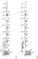
- Fig. 2 and Figure 3 shows a view of the flash evaporator with separator vessel and underlying extruder shafts in the direction parallel to the axes of the extruder.
- the polycarbonate solution is introduced from above through the flash tube 20 or 20 'into the separator 16.
- the vapors are separated in the separator 21 from the concentrated polymer solution.
- the vapors are fed through the vapor line 22 of the condensation.
- the concentrated polymer solution strikes predominantly directly on the extruder shaft 25 and smaller on the cone 23, from where it flows under the action of gravity to the extruder shaft.
- the extruder shafts are arranged in the upwardly opened extruder housing 24.
- the Yellowness Index YI was determined according to ASTM E 313 on injection molded samples of 4 mm thickness.
- the spraying temperature was 300 ° C.
- the relative viscosity is the ratio of the viscosity of a solution of 0.5 g of polycarbonate in 100 ml of dichloromethane to the viscosity of the pure solvent at 25 ° C.
- 6.5 t / h of polycarbonate were isolated in a device according to the invention from a solution of 65% by weight of polycarbonate, 33.5% by weight of chlorobenzene and 1.5% by weight of methylene chloride.
- the Ausdampffextruder was designed as a close-meshed, co-rotating twin-screw extruder and had a screw diameter of 178 mm, a ratio of length of the extruder to the diameter of 48 and was carried out in the feed zone and the degassing zonesteilteilteil innovation.
- the flash evaporator consisted of a 150 mm diameter pipe slit at the bottom. The inlet temperature into the flash evaporator was 230 ° C. In a Schleppschzone 13 kg / h of nitrogen were supplied.
- the isolated polycarbonate had a relative viscosity of 1.295.
- the residual content of chlorobenzene in the isolated polycarbonate was 330 ppm and the content of dichloromethane was below the detection limit of 0.5 ppm.
- the maximum temperature at the nozzle of the extruder was 391 ° C.
- the yellowness index of the polycarbonate was 1.7.
- 6.5 t / h of polycarbonate were isolated in an extruder with backward degassing from a solution of 65% by weight of polycarbonate, 33.5% by weight of chlorobenzene and 1.5% by weight of methylene chloride.
- the Ausdampffextruder was carried out analogously to the example of the invention as tightly meshing, co-rotating twin-screw extruder and had a screw diameter of 178 mm, a ratio of length of the extruder to the diameter 48 and was carried out in the feed zone and the degassing two-speed.
- 13 kg / h of nitrogen were fed.
- the temperature of the polymer solution from the backward degassing was 185 ° C.
- the entry into the extruder was via a valve.
- the isolated polycarbonate had a relative viscosity of 1.295.
- the residual content of chlorobenzene in the isolated polycarbonate was 410 ppm and the content of dichloromethane was 0.5 ppm.
- the temperature at the die of the extruder was 409 ° C.
- the yellowness index of the polycarbonate was 2.3.
Landscapes
- Chemical & Material Sciences (AREA)
- Chemical Kinetics & Catalysis (AREA)
- Engineering & Computer Science (AREA)
- Mechanical Engineering (AREA)
- Dispersion Chemistry (AREA)
- Health & Medical Sciences (AREA)
- Medicinal Chemistry (AREA)
- Polymers & Plastics (AREA)
- Organic Chemistry (AREA)
- Polyesters Or Polycarbonates (AREA)
- Processes Of Treating Macromolecular Substances (AREA)
- Processing And Handling Of Plastics And Other Materials For Molding In General (AREA)
Description
- Die Erfindung betrifft eine Vorrichtung und ein Verfahren zum Entgasen von lösungsmittelhaltigen Polycarbonatlösungen. Durch Anwendung der erfindungsgemäßen Vorrichtung werden Polycarbonate mit niedrigen Restwerte an flüchtiger Bestandteile aus lösungsmittelhaltigen Polymerschmelzen hergestellt, die verbesserte optische Eigenschaften, insbesondere Yellowness Index (YI), mit Hilfe einer Apparate-Kombination aus einem Flashverdampfer und einem Entgasungsextruder.
- Im bekannten Grenzflächenverfahren zur Herstellung von Polycarbonaten werden Lösungsmittel wie aromatische Chlorkohlenwasserstoffe, insbesondere Dichlormethan eingesetzt, deren Restgehalte im Endprodukt unerwünscht sind, da sie im Polycarbonat stören. Um diese flüchtigen Bestandteile zu entfernen muss der Ausdampfextruder nach den aus dem Stand der Technik bekannten Verfahren bei höheren Temperaturen betrieben werden, wodurch thermische Schädigungen entstehen, was den Nachteil verschlechterter optischer Eigenschaften aufweist.
- Eine effiziente Aufkonzentrierung der Polycarbonatlösung und Ausdampfung der Restgehalte an Lösungsmittel bei niedrigen Temperaturen ist deswegen von höchster Bedeutung um Polycarbonate mit verbesserten optischen Eigenschaften zu erlangen.
- Das Verfahren zur Polycarbonatsynthese nach dem Phasengrenzflächenverfahren ist mannigfaltig in der Literatur beschrieben, so unter anderem bei Schnell, "Chemistry and Physics of Polycarbonates", Polymer Reviews, Volume 9, Interscience Publishers, New York, London, Sydney 1964, Seite 33-70.
- Bei dem Phasengrenzflächenverfahren erfolgt die Phosgenierung eines in wässrig-alkalischer Lösung (oder Suspension) vorgelegten Dinatriumsalzes eines Bisphenols (oder eines Gemisches verschiedener Bisphenole) in Gegenwart eines inerten organischen Lösungsmittels oder Lösungsmittelgemisches, welches eine zweite Phase ausbildet. Die entstehenden, hauptsächlich in der organischen Phase vorliegenden, Oligocarbonate werden mit Hilfe geeigneter Katalysatoren zu hochmolekularen, in der organischen Phase gelösten, Polycarbonaten aufkondensiert. Die organische Phase wird schließlich abgetrennt und in einem mehrstufigen Verfahren gewaschen, um Reste von Natrium und Katalysator zu entfernen. Typischerweise enthält die organische Phase nach der Reaktion 10-20 Gew.-% Polycarbonat.
- Das Polycarbonat muss anschließend aus der organischen Phase isoliert werden. Die gängigen Verfahren zur Konzentrierung der Polycarbonatlösung und zur Isolierung des Polycarbonats sind in der Patentliteratur und in Lehrbüchern beschrieben und dem Fachmann geläufig. Die Isolierung des Polycarbonats aus der Lösung wird bevorzugt durch Verdampfen des Lösungsmittels mittels Temperatur oder Vakuum durchgeführt. Dieses Verfahren erfordert, um nach dem Verdampfen des Lösungsmittels direkt die Schmelzephase zu erhalten, den Einsatz eines hoch siedenden (>100°C) Lösungsmittels, beispielsweise Chlorbenzol. Um die Löslichkeit des Polymers im Lösungsmittel während der Reaktion zu verbessern, wird auch ein Gemisch aus einem oder mehreren hochsiedenden Lösungsmitteln und dem niedrig siedenden Dichlormethan eingesetzt. Typischerweise ist das Gewichtsverhältnis von Dichlormethan zu dem hochsiedenden Lösungsmittel etwa 1:1.
- Eine weitere Möglichkeit liegt in der Eindüsung eines erhitzten Gases, insbesondere Wasserdampf, zum Austreiben der flüchtigen Bestandteile. Dabei wird die Polycarbonatlösung mit dem Trägergas versprüht, und Polycarbonat fällt als Feststoff an, insbesondere als wasserfeuchte Suspension. Andere Isolierungsmethoden sind die Kristallisation und Fällung sowie das Ausheizen der Reste des Lösungsmittels in der festen Phase. Letzteres Verfahren erfordert den Einsatz von Dichlormethan als Lösungsmittel, wobei Restgehalte an flüchtigem Lösungsmittel von etwa 2 ppm Dichlormethan erreicht werden können.
- Restgehalte an Dichlormethan stören allerdings im Polycarbonat besonders, da Dichlormethan bekanntermaßen beim Verarbeitungsprozess mit Restfeuchte zusammen Salzsäure abspaltet und so zu Verfärbungen des Polycarbonats und zu Korrosion an Werkzeugen führen kann. Dichlormethan kann bei erhöhten Temperaturen auch im Aufarbeitungsprozess zu Qualitätseinbußen wie Verfärbungen und Gelbildung führen.
- Bei den bekannten Verfahren zur Verdampfung, oder auch Flashverdampfung, werden Polycarbonatlösungen wiederholt unter leichtem Überdruck auf Temperaturen oberhalb des Siedepunktes erhitzt und diese überhitzten Lösungen anschließend in einen Behälter entspannt, wobei in dem Behälter ein niedrigerer Druck herrscht, als dem Dampfdruck in der Lösung entspricht. Die Wiederholung des Verfahrens ist im Allgemeinen günstig, da die Konzentration an Polycarbonat in der Lösung nach der Reaktion relativ niedrig ist und durch die Wiederholung des Verfahrens eine starke Überhitzung vermieden werden kann. Gängige Verfahren für die apparative Eindampfung von Polycarbonatlösungen sind dem Fachmann geläufig. Beispielsweise kann die überhitzte Lösung in ein beheiztes Wendelrohr entspannt werden, welches in einen Abscheider mündet.
- Oberhalb einer bestimmten Konzentration an Polycarbonat (etwa 60 Gew.-%) wird die Eindampfung durch Flashverdampfung durch die hohen Viskositäten erschwert. Die Eindampfung bis zu etwa 60% wird im Weiteren als Voreindampfung bezeichnet. Im Allgemeinen ist es günstig, das restliche Lösungsmittel mit anderen Verfahren, Apparaten und Maschinen zu entfernen. Dies können z.B. Ausdampfextruder oder vertikale Rohrverdampfer sein. Als letzte Stufe können auch Strang- oder Schaumverdampfer eingesetzt werden, um besonders niedrige Restgehalte zu erreichen.
- Bei dem Eindampfen von Polycarbonat werden nach dem Stand der Technik meist zu hohe Apparate-Temperaturen und zu lange Verweilzeiten der Schmelze in den Apparaten angewendet, bei denen zwar eine hinreichende Restentgasung der Polycarbonatschmelze von den flüchtigen Bestandteilen erfolgt, allerdings eine Schädigung des so hergestellten Polycarbonats eintritt. Diese Produktschädigungen sind meist eine direkte Folge von zu hoher Temperatur-Belastung bei zu langer Verweilzeit der Polymerschmelze in den Entgasungsapparaten. Dabei treten Nebenreaktionen am Polycarbonat auf, die eine Verschlechterung der optischen Eigenschaften bewirken, insbesondere die Bildung von Fehlstrukturen, die in den aus solchem Polycarbonat hergestellten Formkörpem meist erst im UV-Licht sichtbar werden. Beispiele für solche Fehlstrukturen sind feinste Partikel und Gelkörper. Bei der Verarbeitung von Polycarbonat zu optischen Datenträgern, wie z.B. CDs oder DVDs, bewirken solche Fehlstrukturen im Endprodukt eine erhebliche Qualitätseinbuße, die nicht mehr tolerabel ist und vermieden werden muss.
- Aufkonzentrierungen von Chlorbenzol-haltigen Polycarbonatlösungen sind in
EP-A 1 265 944 undEP-A1 113 848 - Ausdampf-oder Entgasungsextruder sind dem Fachmann im Prinzip bekannt und beispielsweise in [1] beschrieben. Kennzeichnend für Entgasungextruder sind die sogenannten Entgasungsdome oder Entgasungsöffnungen. Dies sind Gehäuse mit Öffnungen, durch die die enstehenden Brüden entweichen können. Verschiedene Entgasungsdome können bekanntlich bei verschiedenen Drücken betrieben werden, wenn zwischen den Entasungsdömen das Produkt abgestaut wird, so dass es eine Abdichtung zwischen den verschiedenen Drücken bildet.
- Solche Restentgasungen von Polycarbonatlösungen mit Hilfe von Ausdampfextrudem werden in
DE 29 08 352 undEP 1 165 302 beschrieben. In diesen beiden Extruder-Verfahren wird am Extrudereintritt eine sogenannte Rückwärtsentgasung beschrieben. Dabei wird eine gegebenenfalls vorgeheizte Polymerlösung in einen Zweischneckenextruder eingebracht und schäumt dort auf. Die Gase werden dann durch die Gänge des Zweischneckenextruders rückwärts zu einem Entgasungsdom abgeführt. Allgemein ist eine derartige Rückwärtsentgasung Stand der Technik und z.B. in dem Lehrbuch "Der gleichläufige Doppelschneckenextruder", Klemens Kohlgrüber, Carl Hanser Verlag, ISBN 978-3-446-41252-1, auf den Seiten 193-195 beschrieben. Ein Nachteil der Rückwärtsentgasung ist eine Limitierung in der Menge an abgedampftem Lösungsmittel, weil die Schneckenkanäle relativ eng sind und dadurch hohe Gasgeschwindigkeiten erreicht werden, die zu Mitriss von Produkt in den rückwärts gelegenen Entgasungsdom führen kann. So muss ein relativ hoher Anteil an Restlösungsmittel in den weiteren Stufen des Extruders ausgedampft werden, wenn 65- bis 75 Gew-%ige Polycarbonatlösungen in diese Apparate eingeführt werden und bis auf wenige ppm bezogen auf die gesamte Polycarbonatmasse Restlösungsmittelgehalte im Polycarbonat eingedampft werden sollen. Dabei können thermische Schädigungen des Polycarbonats auftreten, wie z.B. Vergilbungen, Bildung von unlöslichen Bestandteilen, Stippen, Spaltung der Polymerketten, Bildung von Restmonomeren und anderen niedermolekulaten Bestandteilen etc. Auch ist nachteilhaft, wenn direkt in einen Extruder eine Polycarbonatlösung mit Restgehalten an Lösungsmittel, wie Dichlormethan, eingespeist wird, da die dem Fachmann wohl bekannte Überhitzung der Lösung an den Kämmen der Schnecke in Gegenwart von beispielsweise Dichlormethan zu lokaler Produktschädigung und damit zu Verfärbung des Gesamtproduktes führt. - Weiterhin offenbart
EP-A 027 700 -
JP 05017516 -
EP-A 1 510 530 schildert ein Verfahren, bei dem eine in einem Wärmetauscher unter einer Druckhaltung überhitzte Polymerlösung einem Ausdampfextruder zugeführt wird. Die entstehenden Gase werden dann durch Vorwärts- und Rückwärtsentgasung aus dem Extruder entfernt. Damit leidet dieses Verfahren unter den gleichen Limitierungen durch hohe Gasgeschwindigkeiten in den engen Schneckenkanälen wie die Verfahren zur Rückwärtsentgasung sowie an der lokalen Überhitzung an den Schneckenkämmen in Gegenwart von Dichlormethan. Wie an den Beispielen 60 bis 65 inEP-A 1 510 530 für Polycarbonatlösungen dargestellt wurde, liegen die Restlösungsmittelgehalte z.T. deutlich über 1000 ppm, was für die meisten Anwendungen nicht tolerabel ist. - In
EP 1 113 848 B1 wurde für die letzte Stufe der Eindampfung eine Kombination aus Rohr- und Strangverdampfer beschrieben. Dabei wird die Polymerlösung zunächst in einem vertikalen Rohrbündelwärmetauscher mit nachgeschaltetem Abscheider, ausgehend von einer Lösung mit 60 bis 75 Gew.-% Polycarbonat, auf 98 bis 99 Gew.-% aufkonzentriert und anschließend in einem Strangverdampfer auf Restgehalte von 5 bis 500 ppm Chlorbenzol aufkonzentiert wird. Bei der Verwendung eines Strangverdampfers wird die Polymerschmelze in einem Abscheider unter Vakuum und erhöhter Temperatur zu feinen Strängen geformt und so vom Lösungsmittel befreit. Der Nachteil der Strangverdampfertechnik liegt darin, dass eine effektive Entgasung nur durch stabile, das bedeutet im Apparat nicht abreißende, Stränge gewährleistet ist. Die Stabilität der Stränge wird durch die Viskosität der Polymerlösung beeinflusst. Eine zu niedrige Viskosität kann zu Strangabrissen führen. Das bedeutet eine Einschränkung der Betriebsparameter hinsichtlich Temperatur und Eintrittsgehalt an restflüchtigen Bestandteilen. Neben dem negativen Einfluss auf die Viskosität hat eine zu hohe Eintrittskonzentration an flüchtigen Bestandteilen direkt nachteilige Auswirkungen auf den erzielbaren Entgasungserfolg, da der Stoffaustausch rein durch Diffusion bestimmt ist. Die Oberfläche für den Stoffaustausch ist dagegen durch die Stranggeometrie festgelegt. Die erforderliche große Fläche des Schmelzeverteilers, der zum Erzeugen der Stränge erforderlich ist, erfordert zudem große, teure Apparate. Diese großen Apparate wiederum haben zwangsläufig große Flächen, die, vor allem im Austrag, mit geringen Strömungsgeschwindigkeiten durchströmt werden. Derartige geringe Strömungsgeschwindigkeiten führen zu langen Verweilzeiten des Polycarbonats in der Nähe der Wände und induzieren dort unerwünschte Veränderungen im Polycarbonat, wie Verfärbung und Bildung von Gel. - Es bestand daher die Aufgabe, eine Vorrichtung und ein Verfahren zum Entgasen von lösungsmittelhaltigen Polycarbonatlösungen bereitzustellen, bei dem die Bildung derartiger unerwünschter Veränderungen im Polycarbonat vermieden wird. Es war insbesondere Aufgabe der Erfindung die bestehende Vorrichtung zur Entgasung und das bestehende Entgasungsverfahren für Polycarbonatlösungen so zu verbessern, dass hohe Polycarbonatschmelzetemperaturen bei längeren Verweilzeiten vermieden und dennoch geringe Rest-Lösungsmittelgehalte im fertigen Polycarbonat erreicht werden.
- Die Aufgabe wird überraschenderweise dadurch gelöst, eine Restentgasung mit Hilfe einer Apparate-Kombination aus Flashverdampfer und Ausdampfextruder durchgeführt wird. Polycarbonatlösungen, die aromatische Chlor-Kohlenwasserstoffe wie z.B. Chlorbenzol als Lösungsmittel enthalten, werden dieser Apparatekombination zugeführt; dabei wird der Flashverdampfer als erste Verfahrensstufe von der Polycarbonatlösung durchlaufen und der Ausdampfextruder als zweite nachgeschaltete Verfahrensstufe.
- Der erfindungsgemäß verwendete Flashverdampfer ist auf einem Abscheider angeordnet und mit diesem unmittelbar verbunden. Die Öffnung oder Öffnungen des Flashverdampfers, die mit Polycarbonatlösung beaufschlagt sind, münden frei in diesen Abscheider, der seinerseits über den unteren Konus frei und unabsperrbar direkt mit einem Extrudergehäuse des Ausdampfextruders verbunden ist, sodass die aus dem Rohrbündelwärmetauscher austretende aufkonzentrierte Polycarbonatlösung unmittelbar in den Ausdampfextruder gelangen kann.
- Gegenstand der Erfindung ist somit eine Vorrichtung und ein Herstellverfahren zur Entfernung flüchtiger Bestandteile aus lösungsmittelhaltigen Polymerschmelzen, insbesondere aus aromatische Chlorkohlenwasserstoffe enthaltenden Polycarbonatlösungn mit Hilfe einer Apparate-Kombination aus einem Flashverdampfer und einem Ausdampfextruder, wobei der Flashverdampfer auf einem Abscheider angeordnet und mit diesem unmittelbar verbunden ist, die Öffnung(en) des Flashverdampfers frei in diesen Abscheider münden, und dieser Abscheider über den unteren Konus frei und unabsperrbar direkt mit einem Extrudergehäuse des Ausdampfextruders verbunden ist und das Eintrittsorgan des Flashverdampfers in Form eines oder mehrerer im Wesentlichen waagrechte Rohre mit Öffnungen nach unten ausgeführt ist.
- In einer besonders bevorzugten Ausführungsform wird diese Apparate-Kombination mit Bürdenleitungen ausgelegt, so dass die Abführung der im Flashverdampfer entstehenden lösungsmittelhaltigen Brüden direkt aus dem Gehäuse des Flashverdampfers über Abscheider und Kondensatoren erfolgt. Je nach Druck im Abscheider, erfolgt die Abführung der Bürden über eine Vakuumstation.
- In einer weiteren Ausführungsform des erfindungsgemäßen Verfahrens ist eine Eindüsung und Vermischung von inerten Komponenten wie beispielsweise Stickstoff, Argon, Kohlendioxid, Wasser, Methan oder Helium oder eine Mischung aus einer oder mehrerer dieser Komponenten, bevorzugt Stickstoff als Schleppmittel in den Polymerschmelzestrom vor dem Flashverdampfer.
- In einer weiteren besonders bevorzugten Ausführungsform des erfindungsgemäßen Verfahrens erfolgt die Eindüsung von Inertgas als Schleppmittel an einem oder mehreren Gehäusen des Ausdampfextruders.
- Durch die dem Extruder vorgelagerte Eindampfung in dem Flashverdampfer kann die Drehzahl des Extruders gesenkt und so die Temperatur, und somit die Produktschädigung, verringert werden.
- Der Flash-Verdampfer besteht bevorzugt aus einem Eintrittsorgan und einem Abscheider. Das Eintrittsorgan sorgt für den Produkteintritt in den Gasraum des Abscheiders, in dem sich die Polymerlösung von den abgetrennten flüchtigen Bestandteilen trennt, sowie einer Abführung für die entstehenden gasförmigen Brüden.
- Das Eintrittsorgan kann auf verschiedene Weise ausgeführt sein, beispielsweise als Flashventil, als Verteilerplatte mit vorgeschaltetem Produktverteiler oder als ein oder mehrere im Wesentlichen waagrechte Rohre mit Öffnungen nach unten ausgeführt sein. Bevorzugt werden Verteilerplatten mit vorgeschaltetem Produktverteiler oder ein im Wesentlichen waagrechtes Rohr mit Öffnungen nach unten. "Im wesentlichen waagrecht" heißt, dass das Rohr der gegenüber der Waagrechten einen Winkel von max. 20°C, bevorzugt von max. 10° und besonders bevorzugt einen Winkel von 0° hat.
- In einer bevorzugten Ausführungsform wird die erfindungsgemäße Vorrichtung zur Entgasung von Polycarbonatlösungen, bevorzugt aus dem Grenzflächenverfahren, enthaltend wenigstens ein organisches Lösungsmittel. Im Rahmen dieser Anmeldung sind die Begriffe Polycarbonatlösungen und Polycarbonatschmelzen als gleichwertig anzusehen.
- Die 65- bis 75-Gew%-ige Polycarbonatlösung wird bevorzugt mit dem Pumpendruck aus der vorangehenden Aufkonzentrierungsstufe in dieses Rohr geleitet und entspannt sich an den Bohrungen unter Verdampfen des Lösungsmittels als aufkonzentrierte Polycarbonatlösung in das unmittelbar darunter liegende Gehäuse des Ausdampfextruders. Der Druck beim Eintritt in das Eintrittsorgan liegt bevorzugt im Bereich von 1,5 bis 15 bar und der Druck im Abscheider von 0,3 bis 6 bar.
- In einer Ausführungsform kann dem Flash-Verdampfer noch ein Wärmeübertrager vorangeschaltet sein, um auf diese Weise eine ausreichende Verdampfungsenergie bereitzustellen. Die Polycarbonatlösungstemperaturen liegen bevorzugt im Bereich von 180°C bis 300°C, besonders bevorzugt von 200°C bis 250°C.
- Auf diese Weise wird dem Ausdampfextruder eine höher konzentrierte und auch kältere Polycarbonatlösung zugeführt. Die Effizienz des Ausdampfextruders wird auf diese Weise gesteigert, da nur noch ein geringerer Energie-Eintrag für die verbleibende Restentgasung der konzentrierteren Polycarbonatlösung erforderlich ist, und da eine geringere Brüdenmenge über dessen Entgasungsöffhungen abgeführt werden muss. Diese Effizienzsteigerung im Ausdampfextruder ermöglicht eine Verringerung der Temperatur und der Verweilzeit der Polycarbonatlösung im Extruder und führt so zu einer schonenden Restentgasung des Polycarbonats im Sinne der Erfindung.
- Die Öffnungen der bevorzugten Flashorgane Verteilerplatte und waagrechtes Rohr sind bevorzugt so angeordnet, dass sie über den Schneckenwellen liegen, so dass Polymerlösung, die aus den Bohrungen austritt, der Schwerkraft folgend im Wesentlichen auf die Schneckenwelle oder Schneckenwellen fällt und direkt eingezogen werden kann. Die Öffnungen können dabei erfindungsgemäß so gestaltet werden, dass vor den Öffnungen ein- oder zweiphasige Strömung herrscht. Für eine einphasige Strömung oberhalb der Öffnungen werden die Öffnungen bevorzugt so ausgeführt, dass sie bei Durchströmung einen Druckverlust haben, der mindestens dem Dampfdruck der Polycarbonatlösung im Eintritt entspricht. Aus den dem Fachmann bekannten Beziehungen zwischen Temperatur und Lösungsmittelkonzentration einer Polycarbonatlösung sowie dem Molekulargewicht sowie dem Dampfdruck und der Viskosität dieser Polymerlösung kann der Fachmann eine Auslegung finden, die die Einphasigkeit oberhalb der Düsenplatte garantiert. Wird eine Zweiphasigkeit angestrebt, so wird bevorzugt ein Druckhalteventil in die Leitung vor dem Rohr oder vor der Verteilerplatte verwendet.
- Die Form der Öffnungen kann beispielsweise rund, oval oder schlitzförmig ausgeführt sein. Die kleinsten Abmessungen der Öffnungen senkrecht zur Flussrichtung der Öffnungen (Breite beim Schlitz, kleiner Halbmesser bei einer Ellipse, Durchmesser bei der kreisförmigen Öffnung) sind erfindungsgemäß zwischen 2 mm und 50 mm, bevorzugt zwischen 5 mm und 30 mm. Die Zahl der Bohrungen wird bevorzugt so gewählt, dass der Durchsatz pro Bohrung von 5 kg/h bis 100 kg/h, bevorzugt von 10 kg/h bis 50 kg/h und besonders bevorzugt von 20 kg/h bis 30 kg/h liegt. Die Anordnung der Bohrungen erfolgt bevorzugt in Reihen parallel zur Extruderachse, besonders bevorzugt in quadratischer Anordnung oder in einer Anordnung, in der die Mittelpunkte der Bohrungen den Eckpunkten eines gleichseitigen Dreiecks entsprechen.
- Die Temperatur der Polymerlösung, die in den Flashverdampfer-Eintritt, liegt zwischen 180°C und 300°C und bevorzugt zwischen 200°C und 250°C. Der Absolutdruck im Abscheider des Flash-Verdampfers liegt zwischen 0,3 und 6 bar, bevorzugt zwischen 0,5 und 4 bar und besonders bevorzugt zwischen 1 und 2 bar.
- In einer bevorzugten Ausführung wird die Polymerlösung vor Eintritt in den Flashverdampfer mittels eines oder mehrere Wärmeübetragers auf die Temperatur erwärmt, die es am Eintritt hat. Die Wärmeübertrager, die dafür in Frage kommen, sind dem Fachmann wohlbekannt. Beispielsweise können hierfür Glattrohrbündelwärmeübertrager, Rohrbündelwärmeübertrager, die bevorzugt mit eingebauten Statikmischem zur Verbesserung des Wärmeübergangs oder Plattenwärmeübertrager sein. Die Polymerlösung befindet sich dabei bevorzugt im Inneren der Rohre. Die Zahl der Passagen dieser Wärmeübertrager kann eins oder mehr betragen, bevorzugt wird eins. Bevorzugt sind Glattrohrbündelwärmeübertrager oder Rohrbündelwärmeübertrager, die mit Statikmischern zur Verbesserung des Wärmeübergags ausgerüstet sind. Die Beheizung der Wärmeübertrager kann, wie dem Fachmann bekannt ist, mit flüssigem oder kondensierendem Wärmeträger erfolgen. Für einen flüssigen Wärmeträger sind organische Wärmeträgeröle wie z.B. Marlotherm LH oder Marlotherm N bevorzugt. Ein kondensierender Wärmeübertrager ist bevorzugt kondensierender Wasserdampf oder kondensierendes Wärmeträgeröl wie z.B. Diphyl. Die Heiztemperatur der Wärmeübertrager sollte aus Qualitätsgründen nicht zu hoch gewählt werden; bevorzugt wird eine Differenz zwischen Heiz- und mittlerer kalorischer Austrittstemperatur von kleiner als 40 K, bevorzugt von kleiner als 30 K und besonders bevorzugt von kleiner als 20 K. Die Produktverweilzeit in dem Wärmeübertrager ist bevorzugt kleiner als zehn Minuten, bevorzugt kleiner als fünf Minuten und besonders bevorzugt kleiner als drei Minuten.
- Der oder die Wärmeübertrager werden bevorzugt einphasig betrieben. Hierfür wird auf der Ausgangsseite des Wärmeübertragers bevorzugt ein Druckhalteventil installiert, was den Druck am Austritt für die Polymerlösung größer als der Dampfdruck des Polymers bei Heiztemperatur hält. Bevorzugt wird der Wärmeübertrager von unten nach oben durchströmt.
- Der Abscheider verfügt in einer bevorzugten Ausführungsform im oberen Bereich über mindestens eine Austrittsöffnung zur Abführung gasförmiger Brüden, über mindestens ein Abscheidegefäß, auf dessen Boden sich vom Brüdenstrom mitgerissene Schmelzepartikel abscheiden können, und über eine Brüden-Kondensationseinrichtung. Hinter der Kondensationseinrichtung kann eine Anlage zur einer Vakuumerzeugung mit Druckregelung vorhanden sein.
- Die Polycarbonat-Lösung enthält bevorzugt 65 - 95 Gew.% Polycarbonat, bezogen auf das Gesamtgewicht der Polycarbonat-Lösung.
- Durch die in einer bevorzugten Ausführungsform zusätzliche Einführung von Schleppgasen vor dem Flash-Verdampfer und/oder im Ausdampfextruder wird der Grad der Restentgasung der Polycarbonatlösung auf schonende Weise weiter verbessert. Das besonders leichflüchtige Dichlormethan wird auf diese Weise fast vollständig abgetrennt, bevor es in Kontakt mit den Wellen des Extruders kommt, wodurch der schädliche Einfluss des Dichlormethans auf die Farbe vermieden wird.
- In einer speziellen Ausführungsform des erfindungsgemäßen Polycarbonatrestentgasüngsverfahrens wird der oben beschriebenen Kombination aus Flashverdampfer und Ausdampfextruder ein weiterer Flashverdampfer oder Fallrohrverdampfer vorangestellt, in den eine 55- bis 80 Gew-%-ige Polycarbonat-Lösung in einem ersten Verfahrensschritt eingeleitet und vorkonzentriert wird. Die so auf 70 bis 95 Gew.%, bevorzugt auf 80 bis 90 Gew.% Polycarbonat vorkonzentrierte Lösung wird anschließend dem oben beschriebenen zweiten Flashverdampfer, der unmittelbar mit dem Ausdampfextruder verbunden ist, zugeführt. Auf diese Weise gelingt es, die Zufuhr der zur Verdampfung der flüchtigen Bestandteile in der Polycarbonatlösung erforderliche Wärmemenge auf mehrere Apparate zu verteilen und die Apparate-Temperaturen so zu wählen, dass Überhitzungen der Polycarbonatlösung sowie die damit verbundenen Nebenreaktionen vermieden werden können.
- Der Werkstoff für den Flashverdampfer soll gegenüber den Korrosionsangriffen durch Dichlormethan beständig sein und das Polycarbonat nicht schädigen. Bevorzugt wird ein eisenarmes oder eisenfreier Werkstoff eingesetzt. Bevorzugt sind nickelbasierte Werkstoffe mit Eisengehalten kleiner als 4 Gew.%, besonders bevorzugt die Legierungen mit den Werkstoffnummern (lt Stahlschlüssel 2007, Verlag Wegst GmbH): 2.4605 (NiCr23Mo16A1) und 2.4610 (Nimo16Cr16Ti). Die Polymerkonzentration am Eintritt in den Extruder beträgt zwischen 80 und 99 Gew.%, bevorzugt 90 bis 99 Gew.%.
- Der Ausdampfextruder kann ein- oder mehrwellig ausgeführt sein, bevorzugt ein-, zwei-oder vierwellig, ganz besonders bevorzugt zweiwellig. Die Ausführung eines mehrwelligen Ausdampfextruders kann gleich- oder gegenläufig, dicht kämmend oder tangierend sein oder, im Fall von vier oder mehr Wellen, eine Kombination aus dicht kämmend und tangierend. Besonders bevorzugt wird die Ausführung als dicht kämmender, gleichläufiger Doppelschneckenextruder gestaltet.
- In einer Ausführungsform können beispielsweise Schneckenelemente für mehrwellige Schneckenmaschinen mit paarweise gleichsinnigen und paarweise exakt abschabenden Schneckenwellen, mit zwei oder mehr Schneckengängen Z, mit Achsabstand A und Außendurchmesser DE, wobei die Summe der Kammwinkel eines Elementepaares größer als 0 und kleiner ist als

DE 10 2008 029305.9 . - In einer weiteren Ausführungsform können beispielsweise auch Schneckenelemente mit paarweise gleichsinnigen und paarweise exakt abschabenden Schneckenwellen, wobei erzeugendes und erzeugtes Schneckenprofil eine Abfolge von Abdichtungsbereich - Übergangsbereich - Kanalbereich - Übergangsbereich aufweisen, wobei ein Abdichtungsbereich eine Abfolge von Kammbereich - Flankenbereich - Kammbereich ist, ein Kanalbereich eine Abfolge von Nutbereich - Flankenbereich - Nutbereich ist und ein Übergangsbereich eine Abfolge von Schneckenprofilbereichen ist, die mit einem Flankenbereich anfängt und mit einem Flankenbereich endet eingesetzt werden. Die Bereiche eines Schneckenprofils, die gleich dem Schneckenaußenradius sind, werden als Kammbereiche bezeichnet. Die Bereiche eines Schneckenprofils, die gleich dem Kernradius sind, werden als Nutbereiche bezeichnet. Die Bereiche eines Schneckenprofils, die kleiner als der Schneckenaußenradius und größer als der Kernradius sind, werden als Flankenbereiche bezeichnet. Solche Schneckenelemente sind beispielsweise in der zum Anmeldezeitpunkt noch unveröffentlichten deutschen Offenlegungsschrift
DE 10 2008 029306.7 . In einem "Kammbereich" haben die Schneckenelemente ihren größten Durchmesser und reinigen die Wand ab. In einem "Nutbereich" haben die Schneckenelemente ihren kleinsten Durchmesser. In einem "Übergangsbereich" haben die Schneckenelemente weder ihren größten noch ihren kleinsten Durchmesser. - Die Entgasungszonen können zwei- und dreigängig ausgeführt werden, bevorzugt zweigängig.
- Eine hohe Entgasung lässt sich insbesondere erzielen, wenn gemäß einer weiteren besonders bevorzugten Ausführungsform der Extruder in Förderrichtung mehrere Entgasungszonen aufweist, an denen jeweils eine Absaugeinrichtung angeschlossen ist. Sehr gute Ergebnisse wurden mit einem Extruder erzielt, der hinter seiner Einzugsöffnung in Förderrichtung vier bis fünf Entgasungszonen aufweist, wobei an der der ersten Entgasungszone zugeordneten Entgasungsöffnung bevorzugt ein Absolutdruck im Bereich von 50 bis 150 kPa, an der der zweiten Entgasungszone zugeordneten Entgasungsöffnung bevorzugt ein Absolutdruck im Bereich von 0.3 bis 10 kPa, an der dritten und weiteren folgenden Entgasungszonen zugeordneten Entgasungsöffnung bevorzugt ein Absolutdruck im Bereich von 0.1 bis 3 kPa erzeugt wurde, wobei der Druck bevorzugt in jedem Schritt abnimmt. Jede der Entgasungszonen verfügt bevorzugt über einen Entgasungsdom, über den die entstehenden Brüden abgeführt werden. Zwischen den verschiedenen Entgasungszonen des Extruders sind Stauzonen angeordnet, bei denen durch neutrale oder rückfordernde Elemente Druckabfall erzeugt wird, wodurch der freie Querschnitt des Extruders vollständig gefüllt wird. Damit werden unterschiedliche Drücke im Gasraum der Entgasungszonen ermöglicht. Bevorzugt werden Knetelemente oder rückwärtsfördernde Schraubenelemente hierfür eingesetzt.
- In einer bevorzugten Ausführungsform kann die Entgasung im Ausdampfextruder mit einem die Entgasungsoberfläche vergrößernden Schleppmittel positiv beeinflusst werden. Bei dem erfindungsgemäßen Verfahren wird das Schleppmittel vorzugsweise in Förderrichtung zwischen der vorletzten und letzten Entgasungszone zugemischt. Als Schleppmittel kann vorzugsweise Stickstoff verwendet werden. Das Schleppmittel wird in einer Knetzone dispergiert. Der zugeführte Schleppmittelvolumenstrom sollte bevorzugt bei einer Wellendrehzahl kleiner oder gleich 390 U/min vorzugsweise 0,05 bis 0,3 Massen-% betragen. Nach der Entgasungszone werden noch Additive und ggf. ein Strom an aufgeschmolzenem Polymer zugegeben, die in einer Druckaufbauzone mit dem Hauptstrom gemischt werden. Die Druckaufbau- und Mischzone kann ein-, zwei- oder dreigängig ausgeführt werden, bevorzugt werden zwei- oder dreigängige Ausführung und besonders bevorzugt wird eine dreigängige Ausführung. Die dreigängige Ausführung ist mit einer Reduzierung des Durchmessers verbunden, wenn der vorherige Entgasungsteil zweigängig ausgeführt wurde.
- Die nach dem erfindungsgemäßen Verfahren erhältlichen thermoplastischen Polycarbonate haben einen Restgehalt an flüchtigen Substanzen (Lösungsmittel, insbesondere Monochlorbenzol) von maximal 2000 ppm, bevorzugt von 20 bis 1000 ppm und besonders bevorzugt von 50 bis 600 ppm, bezogen auf die Polymermasse. Der Restgehalt an Dichlormethan beträgt maximal 2 ppm, bevorzugt weniger als 1 ppm und besonders bevorzugt weniger als 0,5 ppm (frei von Dichlormethan).
- Für das erfmdungsgemäße Verfahren geeignete Diphenole zur Herstellung von Polycarbonat sind im Stand der Technik vielfach beschrieben.
- Geeignete Diphenole sind beispielsweise Hydrochinon, Resorcin, Dihydroxydiphenyl, Bis-(hydroxyphenyl)-alkane, Bis(hydroxy-phenyl)-cycloalkane, Bis-(hydroxyphenyl)-sulfide, Bis-(hydroxyphenyl)-ether, Bis-(hydroxyphenyl)-ketone, Bis-(hydroxyphenyl)-sulfone, Bis-(hydroxyphenyl)-sulfoxide, α,α'-Bis-(hydroxyphenyl)-diisopropylbenzole, sowie deren alkylierte, kernalkylierte und kernhalogenierte Verbindungen.
- Bevorzugte Diphenole sind 4,4'-Dihydroxydiphenyl, 2,2-Bis-(4-hydroxyphenyl)-1-phenyl-propan, 1,1-Bis-(4-hydroxyphenyl)-phenyl-ethan, 2,2-Bis-(4-hydroxyphenyl)propan, 2,4-Bis-(4-hydroxy-phenyl)-2-methylbutan, 1,3-Bis-[2-(4-hydroxyphenyl)-2-propyl]benzol (Bisphenol M), 2,2-Bis-(3-methyl-4-hydroxyphenyl)-propan, Bis-(3,5-dimethyl-4-hydroxyphenyl)-methan, 2,2-Bis-(3,5-dimethyl-4-hydroxyphenyl)-propan, Bis-(3,5-dimethyl-4-hydroxyphenyl)-sulfon, 2,4-Bis-(3,5-dimethyl-4-hydroxyphenyl)-2-methylbutan, 1,3-Bis-[2-(3,5-dimethyl-4-hydroxyphenyl)-2-propyl]-benzol und 1,1-Bis-(4-hydroxyphenyl)-3,3,5-trimethylcyclohexan (Bisphenol TMC).
- Besonders bevorzugte Diphenole sind 4,4'-Dihydroxydiphenyl, 1,1-Bis-(4-hydroxyphenyl)-phenyl-ethan, 2,2-Bis-(4-hydroxyphenyl)-propan, 2,2-Bis(3,5-dimethyl-4-hydroxyphenyl)-propan, 1,1 -Bis-(4-hydroxyphenyl)-cyclohexan und 1,1-Bis-(4-hydroxyphenyl)-3,3,5-trimethylcyclohexan (Bisphenol TMC).
- Im Falle der Homopolycarbonate wird nur ein Diphenol eingesetzt, im Falle der Copolycarbonate werden mehrere Diphenole eingesetzt, wobei selbstverständlich die verwendeten Diphenole, wie auch alle anderen der Synthese zugesetzten Chemikalien und Hilfsstoffe mit den aus ihrer eigenen Synthese, Handhabung und Lagerung stammenden Verunreinigungen kontaminiert sein können, obwohl es wünschenswert ist, mit möglichst sauberen Rohstoffen zu arbeiten.
- Die zur Regelung des Molekulargewichtes benötigten monofunktionellen Kettenabbrecher, wie beispielsweise Phenol oder Alkylphenole, insbesondere Phenol, p-tert. Butylphenol, iso-Octylphenol, Cumylphenol, deren Chlorkohlensäureester oder Säurechloride von Monocarbonsäuren bzw. Gemischen aus diesen Kettenabbrechern, werden entweder mit dem Bisphenolat bzw. den Bisphenolaten der Reaktion zugeführt oder aber zu jedem beliebigen Zeitpunkt der Synthese zugesetzt, solange im Reaktionsgemisch noch Phosgen oder Chlorkohlensäureendgruppen vorhanden sind bzw., im Falle der Säurechloride und Chlorkohlensäureester als Kettenabbrecher, solange genügend phenolische Endgruppen des sich bildenden Polymers zur Verfügung stehen. Vorzugsweise werden der oder die Kettenabbrecher jedoch nach der Phosgenierung an einem Ort oder zu einem Zeitpunkt zugegeben, wo kein Phosgen mehr vorliegt, aber der Katalysator noch nicht dosiert wurde. Alternativ können sie auch vor dem Katalysator, mit dem Katalysator zusammen oder parallel zudosiert werden.
- In der gleichen Weise werden ggf. Verzweiger oder Verzweigermischungen der Synthese zugesetzt. Üblicherweise werden Verzweiger jedoch vor den Kettenabbrechern zugesetzt. In der Regel werden Trisphenole, Quarterphenole oder Säurechloride von Tri- oder Tetracarbonsäuren oder Gemische der Polyphenole oder der Säurechloride verwendet. Einige der als Verzweiger geeignete Verbindungen mit drei oder mehr als drei phenolischen Hydroxylgruppen sind beispielsweise Phloroglucin, 4,6-Dimethyl-2,4,6-tri-(4-hydroxyphenyl)-hepten-2, 4,6-Dimethyl-2,4,6-tri-(4-hydroxyphenyl)-heptan, 1,3,5-Tri-(4-hydroxyphenyl)-benzol, 1,1,1-Tri-(4-hydroxyphenyl)-ethan, Tri-(4-hydroxyphenyl)-phenylmethan, 2,2-Bis-(4,4-bis-(4-hydroxyphenyl)-cyclohexyl)-propan, 2,4-Bis-(4-hydroxyphenyl-isopropyl)-phenol, Tetra-(4-hydroxyphenyl)-methan.
- Einige der sonstigen trifunktionellen Verbindungen sind 2,4-Dihydroxybenzoesäure, Trimesinsäure, Cyanurchlorid und 3,3-Bis-(3-methyl-4-hydroxyphenyl)-2-oxo-2,3-dihydroindol.
- Bevorzugte Verzweiger sind 3,3-Bis-(3-methyl-4-hydroxyphenyl)-2-oxo-2,3-dihydroindol und 1,1,1-Tri-(4-hydroxyphenyl)-ethan.
- Die in der Phasengrenzflächensynthese von Polycarbonat bevorzugt verwendeten Katalysatoren sind tertiäre Amine, insbesondere Triethylamin, Tributylamin, Trioctylamin, N-Ethylpiperidin, N-Methylpiperidin, N-i/n-Propylpiperidin, quartäre Ammoniumsalze wie Tetrabutylammonium-, Tributylbenzylammonium-, Tetraethylammonium-hydroxid, -chlorid, -bromid, -hydrogensulfat, - tetrafluoroborat, sowie die den Ammoniumverbindungen entsprechenden Phosphoniumverbindungen. Diese Verbindungen sind als typische Phasengrenzflächenkatalysatoren in der Literatur beschrieben, kommerziell erhältlich und dem Fachmann geläufig. Die Katalysatoren können einzeln, im Gemisch oder auch neben- und nacheinander der Synthese zugesetzt werden, gegebenenfalls auch vor der Phosgenierung, bevorzugt sind jedoch Dosierungen nach der Phosgeneintragung, es sei denn, es werden eine Oniumverbindung oder ein Gemisch aus Oniumverbindungen als Katalysatoren verwendet. In diesem Fall ist eine Zugabe vor der Phosgendosierung bevorzugt. Die Dosierung des Katalysators oder der Katalysatoren kann in Substanz, in einem inerten Lösungsmittel, vorzugsweise dem Lösungsmittel der Polycarbonatsynthese oder auch als wässrige Lösung, im Falle der tert. Amine dann als deren Ammoniumsalze mit Säuren, bevorzugt Mineralsäuren, insbesondere Salzsäure, erfolgen. Bei Verwendung mehrerer Katalysatoren oder der Dosierung von Teilmengen der Katalysatorgesamtmenge können natürlich auch unterschiedliche Dosierungsweisen an verschiedenen Orten oder zu verschiedenen Zeiten vorgenommen werden. Die Gesamtmenge der verwendeten Katalysatoren liegt bei 0,001 bis 10 Mol-% bezogen auf Mole eingesetzte Bisphenole, bevorzugt 0,01 bis 8 Mol-%, besonders bevorzugt 0,05 bis 5 Mol-%.
- Die Durchführung der Polycarbonatsynthese kann kontinuierlich oder diskontinuierlich geschehen. Die Reaktion kann daher in Rührkesseln, Rohrreaktoren, Umpumpreaktoren oder Rührkesselkaskaden oder Kombinationen daraus erfolgen. Dabei ist durch Verwendung der bereits erwähnten Mischorgane sicherzustellen, dass wässrige und organische Phase sich möglichst erst dann entmischen, wenn das Synthesegemisch ausreagiert hat, d.h. kein verseifbares Chlor von Phosgen oder Chlorkohlensäureestern mehr enthält.
- Nach Eintrag des Phosgens kann es vorteilhaft sein, eine gewisse Zeit die organische Phase und die wässrige Phase zu durchmischen, bevor gegebenenfalls Verzweiger, sofern dieser nicht gemeinsam mit dem Bisphenolat dosiert wird, Kettenabbrecher und Katalysator zugegeben werden. Eine derartige Nachreaktionszeit kann nach jeder Dosierung von Vorteil sein. Diese Nachrührzeiten liegen bei 10 Sekunden bis 60 Minuten, bevorzugt 30 Sekunden bis 40 Minuten, besonders bevorzugt 1 bis 15 Minuten.
- Die organische Phase kann aus einem Lösungsmittel oder Mischungen mehrerer Lösungsmittel bestehen. Geeignete Lösungsmittel sind chlorierte Kohlenwasserstoffe (aliphatische und/oder aromatische), bevorzugt Dichlormethan, Trichlorethylen, 1,1,1-Trichlorethan, 1,1,2- Trichlorethan und Chlorbenzol und deren Gemische. Es können jedoch auch aromatische Kohlenwasserstoffe wie Benzol, Toluol, m/p/o-Xylol oder aromatische Ether wie Anisol allein, im Gemisch mit oder zusätzlich zu chlorierten Kohlenwasserstoffen verwendet werden. Eine andere Ausführungsform der Synthese verwendet Lösungsmittel, welche Polycarbonat nicht lösen, sondern nur anquellen. Es können daher auch Nichtlösungsmittel für Polycarbonat in Kombination mit Lösungsmitteln verwendet werden. Dabei können als Lösungsmittel auch in der wässrigen Phase lösliche Lösungsmittel wie Tetrahydrofuran, 1,3/1,4-Dioxan oder 1,3-Dioxolan verwendet werden, wenn der Lösungsmittelpartner die zweite organische Phase bildet.
- Das ausreagierte, höchstens noch Spuren (<2 ppm) an Chlorkohlensäureestern enthaltende mindestens zweiphasige Reaktionsgemisch lässt man zur Phasentrennung absitzen. Die wässrige alkalische Phase wird evtl. ganz oder teilweise zurück in die Polycarbonatsynthese als wässrige Phase geleitet oder aber der Abwasseraufarbeitung zugeführt, wo Lösungsmittel- und Katalysatoranteile abgetrennt und rückgeführt werden. In einer anderen Variante der Aufarbeitung wird nach Abtrennung der organischen Verunreinigungen, insbesondere von Lösungsmitteln und Polymerresten, und gegebenenfalls nach der Einstellung eines bestimmten pH-Wertes, z.B. durch Natronlaugezugabe, das Salz abgetrennt, welches z.B. der Chloralkalielektrolyse zugeführt werden kann, während die wässrige Phase gegebenenfalls wieder der Synthese zugeführt wird.
- Die organische, das Polycarbonat enthaltende Phase kann nun von allen Kontaminationen alkalischer, ionischer oder katalytischer Art gereinigt werden. Die organische Phase enthält auch nach einem oder mehreren Absetzvorgängen noch Anteile der wässrigen alkalischen Phase in feinen Tröpfchen sowie den Katalysator, in der Regel ein tert. Amin. Die Absetzvorgänge können gegebenenfalls dadurch unterstützt werden, dass die organische Phase Absetzkessel, Rührkessel, Coalescer oder Separatoren bzw. Kombinationen daraus durchläuft, wobei gegebenenfalls Wasser in jedem oder einigen Trennschritten unter Umständen unter Verwendung von aktiven oder passiven Mischorganen zudosiert werden kann.
- Nach dieser groben Abtrennung der alkalischen, wässrigen Phase wird die organische Phase ein oder mehrmals mit verdünnten Säuren, Mineral-, Carbon- Hydroxycarbon-und/oder Sulfonsäuren gewaschen. Bevorzugt sind wässrige Mineralsäuren insbesondere Salzsäure, phosphorige Säure und Phosphorsäure oder Mischungen dieser Säuren. Die Konzentration dieser Säuren sollte im Bereich 0,001 bis 50 Gew.-%, bevorzugt 0,01 bis 5 Gew.-% liegen.
- Weiterhin wird die organische Phase mit entsalztem oder destilliertem Wasser wiederholt gewaschen. Die Abtrennung der, gegebenenfalls mit Teilen der wässrigen Phase dispergierten, organischen Phase nach den einzelnen Waschschritten geschieht mittels Absetzkessel, Rührkessel, Coalescer oder Separatoren bzw. Kombinationen daraus, wobei das Waschwasser zwischen den Waschschritten gegebenenfalls unter Verwendung von aktiven oder passiven Mischorganen zudosiert werden kann.
- Zwischen diesen Waschschritten oder auch nach der Wäsche können ggf. Säuren, vorzugsweise gelöst im Lösungsmittel, welches der Polymerlösung zugrunde liegt, zugegeben werden. Bevorzugt werden hier Chlorwasserstoffgas und Phosphorsäure oder phosphorige Säure verwendet, die ggf. auch als Mischungen eingesetzt werden können.
- Diese gereinigte Lösung wird dann im folgenden Schritt der erfindungsgemäßen Flash-Verdampfer/Ausdampf-Extruder Kombination zugeführt.
- Die nach dem erfmdungsgemäßen Verfahren erhaltenen Polycarbonate können zur Veränderung von Eigenschaften mit den üblichen Additiven und Zusatzstoffen (z.B. Hilfs- und Verstärkungsstoffe) versehen werden. Der Zusatz von Additiven und Zuschlagsstoffen dient der Verlängerung der Nutzungsdauer (z.B. Hydrolyse- oder Abbaustabilisatoren), der Verbesserung der Farbstabilität (z.B. Thermo- und UV-Stabilisatoren), der Vereinfachung der Verarbeitung (z.B. Entformer, Fließhilfsmittel), der Verbesserung der Gebrauchseigenschaften (z.B. Antistatika), der Verbesserung des Flammschutzes, der Beeinflussung des optischen Eindrucks (z.B. organische Farbmittel, Pigmente) oder der Anpassung der Polymereigenschaften an bestimmte Belastungen (Schlagzähmodifikatoren, fein zerteilte Mineralien, Faserstoffe, Quarzmehl, Glas- und Kohlenstoffiasem).
- In
Fig. 1 wird die Polymerlösung durch eine Zuführung 1 dem Rohrbündelwärmeübertrager 2 zugeführt. Der Rohrbündelwärmeübertrager wird mit Heizmedium beheizt, das bei 3 zu- und bei 4 abgeführt wird. Der Druck im Wärmeübertrager 2 wird mit dem Ventil V über dem Dampfdruck der Lösung bei Heiztemperatur gehalten. Danach entspannt die Polymerlösung über das Einsteckrohr 5 und die Öffnungen 6 in den Abscheidebehälter 7, der direkt über dem Extruder angeordnet ist. Das freigesetzte Gas wird über die Brüdenleitung 8 abgeführt. Das Produkt fällt direkt in die Einzugszone 9 des Extruders und wird durch eine Stauzone 10 einer ersten Entgasungszone 11 zugeführt, die über einen Entgasungsdom 12 verfügt. Danach folgen weitere Stauzonen 10 und Entgasungszonen 11. Vor dem letzten Entgasungsdom wird in der Knetzone 12 über die Zugabestelle 13 Stickstoff über die Zufuhr 14 zugegeben. Bei der Zugabestelle 15 werden noch Additive und ggf. aufgeschmolzenes Polymer zugegeben, die in der Druckaufbau- und Mischzone 16 mit dem Polymerstrom vermischt werden. -
Fig. 2 und 3 zeigen eine Sicht des Flashverdampfers mit Abscheidebehälters und darunter liegenden Extruderwellen in Richtung parallel zu den Achsen des Extruders. Die Polycarbonatlösung wird von oben durch das Flashrohr 20 oder 20' in den Abscheider 16 gegeben. Die Brüden werden im Abscheider 21 von der konzentrierten Polymerlösung getrennt. Die Brüden werden durch die Brüdenleitung 22 der Kondensation zugeführt. Die konzentierte Polymerlösung trifft überwiegend auf direkt auf die Extruderwellen 25 und zum kleineren auf den Konus 23, von wo sie unter Wirkung der Schwerkraft den Extruderwellen zufließt. Die Extruderwellen sind im nach oben geöffenten Extrudergehäuse 24 angeordnet. - Die folgenden Beispiele dienen der exemplarischen Erläuterung der Erfindung und sind nicht als Beschränkung aufzufassen.
- Der Yellowness Index YI wurde nach ASTM E 313 an spritzgegossenen Proben einer Dicke von 4 mm bestimmt. Die Verspritzungstemperatur war 300°C.
- Die relative Viskosität ist das Verhältnis der Viskosität einer Lösung von 0,5 g Polycarbonat in 100 ml Dichlormethan zur Viskosität des reinen Lösemittels bei 25°C.
- 6,5 t/h Polycarbonat wurden in einer erfindungsgemäßen Vorrichtung aus einer Lösung von 65 Gew-% Polycarbonat, 33,5 Gew-% Chlorbenzol und 1,5 Gew-% Methylenchlorid isoliert. Der verwendete Ausdampfextruder war als dicht kämmender, gleichsinnig drehender Doppelschneckenextruder ausgeführt und hatte einen Schneckendurchmesser von 178 mm, ein Verhältnis von Länge des Extruders zum Durchmesser von 48 und war in der Einzugszone und den Entgasungszonen zweigängig ausgeführt. Der Flashverdampfer bestand aus einem Rohr mit 150 mm Durchmesser, das unten geschlitzt war. Die Eintrittstemperatur in den Flashverdampfer betrug 230°C. In einer Schleppmittelzone wurden 13 kg/h Stickstoff zugeführt. Das isolierte Polycarbonat hatte eine relative Viskosität von 1,295.
- Der Chlorbenzol-Restgehalt im isolierten Polycarbonat betrug 330 ppm und der Gehalt an Dichlormethan war unterhalb der Nachweisgrenze von 0,5 ppm. Die maximale Temperatur, an der Düse des Extruders, betrug 391°C. DerYellowness-Index des Polycarbonats betrug 1,7.
- 6,5 t/h Polycarbonat wurden in einem Extruder mit Rückwärtsentgasung aus einer Lösung von 65 Gew-% Polycarbonat, 33,5 Gew-% Chlorbenzol und 1,5 Gew-% Methylenchlorid isoliert. Der verwendete Ausdampfextruder war analog dem erfindungsgemäßen Beispiel als dicht kämmender, gleichsinnig drehender Doppelschneckenextruder ausgeführt und hatte einen Schneckendurchmesser von 178 mm, ein Verhältnis von Länge des Extruders zum Durchmesser 48 und war in der Einzugszone und den Entgasungszonen zweigängig ausgeführt. In einer Schleppmittelzone wurden, ebenso wie im erfindungsgemäßen Beispiel, 13 kg/h Stickstoff zugeführt. Die Temperatur der Polymerlösung von der Rückwärtsentgasung betrug 185°C. Der Eintritt in den Extruder erfolgte über ein Ventil. Das isolierte Polycarbonat hatte eine relative Viskosität von 1,295.
- Der Chlorbenzol-Restgehalt im isolierten Polycarbonat betrug 410 ppm und der Gehalt an Dichlormethan betrug 0,5 ppm. Die Temperatur an der Düse des Extruders betrug 409°C. Der Yellowness-Index des Polycarbonats betrug 2,3.
Claims (13)
- Vorrichtung zum Entgasen von lösungsmittelhaltigen Polycarbonatschmelzen, dadurch gekennzeichnet, dass ein Flashverdampfer mit einem Ausdampf-Extruder kombiniert wird, wobei der Flashverdampfer auf einem Abscheider angeordnet und mit diesem unmittelbar verbunden ist, die Öffhung(en) des Flashverdampfers frei in diesen Abscheider münden, und dieser Abscheider über den unteren Konus frei und unabsperrbar direkt mit einem Extrudergehäuse des Ausdampfextruders verbunden ist und das Eintrittsorgan des Flashverdampfers in Form eines oder mehrerer im Wesentlichen waagrechte Rohre mit Öffnungen nach unten ausgeführt ist.
- Vorrichtung nach Anspruch 1, dadurch gekennzeichnet, dass am Flashverdampfer Brüdenleitungen angebracht sind, wobei die Abführung der im Flashverdampfer entstehenden lösungsmittelhaltigen Brüden direkt aus dem Gehäuse des Flashverdampfers über Abscheider und Kondensatoren erfolgt.
- Vorrichtung nach Anspruch 1 oder 2, dadurch gekennzeichnet, dass die Beheizung des Flashverdampfers über kondensierenden Wasserdampf, über einen kondensierenden organischen Wärmeträger oder über einen flüssigen organischen Wärmeträger erfolgt.
- Vorrichtung nach einem der Ansprüche 1 bis 3, dadurch gekennzeichnet, dass der Kombination aus einem Flashverdampfer und Ausdampfextruder wenigstens ein weiterer Flashverdampfer/Fallrohrverdampfer vorangestellt ist.
- Vorrichtung nach einem der Ansprüche 1 bis 4, dadurch gekennzeichnet, dass der Ausdampfextruder zwei- oder vierwellig ausgeführt ist.
- Vorrichtung nach einem der Ansprüche 1 bis 5, dadurch gekennzeichnet, dass der Ausdampfextruder ein dicht kämmender, gleichsinnig drehender Doppelschneckenextruder ist.
- Vorrichtung nach einem der Ansprüche 1 bis 6, dadurch gekennzeichnet, dass der Extruder in Förderrichtung mehrere Entgasungszonen aufweist.
- Verfahren zur Entgasung von Polycarbonatlösungen in einer Vorrichtung nach einem der Ansprüche 1 bis 7, dadurch gekennzeichnet, dass eine Polycarbonatlösung, enthaltend wenigstens ein organisches Lösemittel und wenigstens ein Polycarbonat, nach dem Grenzflächenverfahren hergestellt wird und diese Polycarbonat-Lösung in einem zweiten Schritt einem Flashverdampfer in Kombination mit einem Ausdampf-Extruder zugeführt wird, wobei der Flashverdampfer direkt über dem Extruder so angeordnet ist, so dass die Polymerlösung direkt in den Ausdampf-Extruder fällt.
- Verfahren nach Anspruch 8, dadurch gekennzeichnet, dass die Abführung der im Flashverdampfer entstehenden lösungsmittelhaltigen Brüden direkt aus dem Gehäuse des Flashverdampfers über Brüdenleitungen erfolgt.
- Verfahren nach einem der Ansprüche 8 oder 9, dadurch gekennzeichnet, dass eine Eindüsung und Vermischung von Inertgasen als Schleppmittel in den Polymerschmelzestrom vor dem Flashverdampfer erfolgt.
- Verfahren nach einem der Ansprüche 8 bis 10, dadurch gekennzeichnet, dass eine Eindüsung von Inertgas als Schleppmittel an einem oder mehreren Gehäusen des Ausdampfextruders erfolgt.
- Verfahren nach einem der Ansprüche 8 bis 11, dadurch gekennzeichnet, dass die Eingangskonzentration des Polycarbonats in den Flashverdampfer zwischen 60 Gew-% und 95 Gew-% beträgt:
- Verfahren nach einem der Ansprüche 8 bis 12, dadurch gekennzeichnet, dass das Polymer vor dem Eintreten in den Flashverdampfer mittels eines Wärmeübertragers aufgewärmt wird.
Priority Applications (1)
| Application Number | Priority Date | Filing Date | Title |
|---|---|---|---|
| EP10722007.1A EP2435151B1 (de) | 2009-05-30 | 2010-05-26 | Vorrichtung und verfahren zum entgasen von lösungsmittelhaltigen polycarbonatlösungen |
Applications Claiming Priority (3)
| Application Number | Priority Date | Filing Date | Title |
|---|---|---|---|
| EP09007269A EP2255860A1 (de) | 2009-05-30 | 2009-05-30 | Vorrichtung und Verfahren zum Entgasen von lösungsmittelhaltigen Polycarbonatlösungen |
| PCT/EP2010/003206 WO2010139413A1 (de) | 2009-05-30 | 2010-05-26 | Vorrichtung und verfahren zum entgasen von lösungsmittelhaltigen polycarbonatlösungen |
| EP10722007.1A EP2435151B1 (de) | 2009-05-30 | 2010-05-26 | Vorrichtung und verfahren zum entgasen von lösungsmittelhaltigen polycarbonatlösungen |
Publications (2)
| Publication Number | Publication Date |
|---|---|
| EP2435151A1 EP2435151A1 (de) | 2012-04-04 |
| EP2435151B1 true EP2435151B1 (de) | 2016-05-25 |
Family
ID=41151757
Family Applications (2)
| Application Number | Title | Priority Date | Filing Date |
|---|---|---|---|
| EP09007269A Withdrawn EP2255860A1 (de) | 2009-05-30 | 2009-05-30 | Vorrichtung und Verfahren zum Entgasen von lösungsmittelhaltigen Polycarbonatlösungen |
| EP10722007.1A Not-in-force EP2435151B1 (de) | 2009-05-30 | 2010-05-26 | Vorrichtung und verfahren zum entgasen von lösungsmittelhaltigen polycarbonatlösungen |
Family Applications Before (1)
| Application Number | Title | Priority Date | Filing Date |
|---|---|---|---|
| EP09007269A Withdrawn EP2255860A1 (de) | 2009-05-30 | 2009-05-30 | Vorrichtung und Verfahren zum Entgasen von lösungsmittelhaltigen Polycarbonatlösungen |
Country Status (7)
| Country | Link |
|---|---|
| US (1) | US8497345B2 (de) |
| EP (2) | EP2255860A1 (de) |
| JP (1) | JP5844253B2 (de) |
| KR (1) | KR101743310B1 (de) |
| CN (1) | CN102448569B (de) |
| SG (1) | SG175850A1 (de) |
| WO (1) | WO2010139413A1 (de) |
Families Citing this family (8)
| Publication number | Priority date | Publication date | Assignee | Title |
|---|---|---|---|---|
| EP2255859A1 (de) * | 2009-05-30 | 2010-12-01 | Bayer MaterialScience AG | Vorrichtung und Verfahren zum Entgasen von lösungshaltigen Polycarbonatlösungen |
| JP5619239B1 (ja) * | 2013-08-27 | 2014-11-05 | 株式会社日本製鋼所 | ベント式二軸混練押出装置及び方法 |
| CN106139626B (zh) * | 2016-08-25 | 2018-05-08 | 山东恒利热载体工程技术有限公司 | 有机热载体在线气提清除裂解轻组分的工艺及装置 |
| EP3933059A1 (de) | 2020-06-29 | 2022-01-05 | Covestro Deutschland AG | Verfahren zur herstellung eines polycarbonats |
| WO2022090526A1 (en) | 2020-11-02 | 2022-05-05 | Röhm Gmbh | Device for degassing of a two-component multiphase polymer-monomer material and use thereof in a degassing extruder |
| CN113694565B (zh) * | 2021-09-02 | 2023-02-21 | 上海盛普流体设备股份有限公司 | 一种具有分段式螺杆与陶瓷衬套的脱泡装置及其脱泡方法 |
| US20250242533A1 (en) | 2022-04-11 | 2025-07-31 | Covestro Deutschland Ag | Screw elements with improved mixing and degassing effect with reduced energy input |
| CN115260481A (zh) * | 2022-09-05 | 2022-11-01 | 上海华峰新材料研发科技有限公司 | 一种聚合物熔体的脱挥发方法 |
Family Cites Families (27)
| Publication number | Priority date | Publication date | Assignee | Title |
|---|---|---|---|---|
| US2964513A (en) * | 1956-08-20 | 1960-12-13 | Phillips Petroleum Co | Polymer recovery process |
| US3458494A (en) | 1964-07-15 | 1969-07-29 | Phillips Petroleum Co | Process for recovering olefin polymers |
| US3450183A (en) * | 1964-10-02 | 1969-06-17 | Phillips Petroleum Co | Polymer recovery apparatus |
| DE1964946C3 (de) * | 1969-12-24 | 1980-09-18 | Bayer Ag, 5090 Leverkusen | Vorrichtung zum Konzentrieren einer Lösung oder Suspension bis zum plastischen Zustand |
| DE2005691A1 (de) | 1970-02-07 | 1971-08-12 | Bayer Ag | Verfahren zur Herstellung selbstver netzbarer hochreaktiver Pulverlackbinde mittel |
| DE2908352A1 (de) | 1979-03-03 | 1980-09-18 | Bayer Ag | Verfahren zur getrennten ableitung der einzelnen phasenstroeme einer mehrphasenstroemung |
| JPS5653104A (en) | 1979-10-09 | 1981-05-12 | Mitsui Petrochem Ind Ltd | Separation of polymer from polymer solution |
| JPS60260895A (ja) | 1984-06-08 | 1985-12-24 | 株式会社日立製作所 | 放射線施設の内部構造 |
| JPS6162522A (ja) * | 1984-09-03 | 1986-03-31 | Daicel Chem Ind Ltd | ポリエステルカーボネートの製法 |
| DE3628994A1 (de) | 1986-08-26 | 1988-03-03 | Basf Ag | Kontinuierliches verfahren zur entfernung von geloesten stoffen aus polymerloesungen |
| US5024728A (en) * | 1988-08-29 | 1991-06-18 | Dainippon Ink And Chemicals, Inc. | Devolatilization of liquid composition containing polymer and volatile constituents |
| JPH0517516A (ja) | 1991-07-10 | 1993-01-26 | Mitsubishi Rayon Co Ltd | 重合体溶液からの揮発物除去方法 |
| US5283021A (en) * | 1993-06-14 | 1994-02-01 | Chi Mei Corporation | Process for removing the solvent from an elastomeric polymer solution |
| US5708133A (en) | 1993-11-09 | 1998-01-13 | Mitsubishi Gas Chemical Company, Inc. | Process for purifying polymer |
| JP4108819B2 (ja) | 1998-03-27 | 2008-06-25 | 新日鐵化学株式会社 | 重合液組成物の脱揮処理方法 |
| DE19817678A1 (de) * | 1998-04-21 | 1999-10-28 | Bayer Ag | Vorrichtung und Verfahren zur Entfernung von flüchtigen Komponenten aus Polymerlösungen |
| DE19835744A1 (de) | 1998-08-07 | 2000-02-17 | Bayer Ag | Verfahren zum Eindampfen von Polymerlösungen thermoplastischer Polymere |
| DE19914143A1 (de) | 1999-03-27 | 2000-09-28 | Bayer Ag | Vorrichtung und Verfahren zum Entgasen von Kunststoffen, insbesondere von hochmolekularen Polycarbonatlösungen |
| US6620906B1 (en) | 2000-02-07 | 2003-09-16 | Bayer Aktiengesellschaft | Method for the production of highly pure polycarbonate and ultrapure polycarbonate |
| DE10016894A1 (de) | 2000-04-05 | 2001-10-18 | Bayer Ag | Verfahren und Vorrichtung zur Entfernung flüchtiger Bestandteile aus Polymermassen |
| US6403761B2 (en) * | 2000-06-22 | 2002-06-11 | Jsr Corporation | Method for recovering a polymer |
| JP2002047350A (ja) * | 2000-07-31 | 2002-02-12 | Teijin Chem Ltd | ポリカーボネート樹脂粉粒体の製造方法 |
| DE10333577A1 (de) * | 2003-07-24 | 2005-02-24 | Bayer Technology Services Gmbh | Verfahren und Vorrichtung zur Entfernung von flüchtigen Substanzen aus hochviskosen Medien |
| US6949622B2 (en) * | 2003-08-26 | 2005-09-27 | General Electric Company | Method of separating a polymer from a solvent |
| DE102008029305A1 (de) | 2008-06-20 | 2009-12-24 | Bayer Technology Services Gmbh | Schneckenelemente mit reduziertem Kammwinkel |
| DE102008029306A1 (de) | 2008-06-20 | 2009-12-24 | Bayer Technology Services Gmbh | Schneckenelemente mit reduziertem Energieeintrag beim Druckaufbau |
| EP2255859A1 (de) * | 2009-05-30 | 2010-12-01 | Bayer MaterialScience AG | Vorrichtung und Verfahren zum Entgasen von lösungshaltigen Polycarbonatlösungen |
-
2009
- 2009-05-30 EP EP09007269A patent/EP2255860A1/de not_active Withdrawn
-
2010
- 2010-03-26 US US13/322,731 patent/US8497345B2/en not_active Expired - Fee Related
- 2010-05-26 KR KR1020117028507A patent/KR101743310B1/ko not_active Expired - Fee Related
- 2010-05-26 CN CN201080024023.6A patent/CN102448569B/zh not_active Expired - Fee Related
- 2010-05-26 SG SG2011080348A patent/SG175850A1/en unknown
- 2010-05-26 WO PCT/EP2010/003206 patent/WO2010139413A1/de not_active Ceased
- 2010-05-26 JP JP2012512253A patent/JP5844253B2/ja not_active Expired - Fee Related
- 2010-05-26 EP EP10722007.1A patent/EP2435151B1/de not_active Not-in-force
Non-Patent Citations (1)
| Title |
|---|
| None * |
Also Published As
| Publication number | Publication date |
|---|---|
| EP2255860A1 (de) | 2010-12-01 |
| US20120123084A1 (en) | 2012-05-17 |
| EP2435151A1 (de) | 2012-04-04 |
| US8497345B2 (en) | 2013-07-30 |
| CN102448569B (zh) | 2016-06-01 |
| CN102448569A (zh) | 2012-05-09 |
| KR101743310B1 (ko) | 2017-06-15 |
| JP2012528896A (ja) | 2012-11-15 |
| KR20120036814A (ko) | 2012-04-18 |
| JP5844253B2 (ja) | 2016-01-13 |
| WO2010139413A1 (de) | 2010-12-09 |
| SG175850A1 (en) | 2011-12-29 |
Similar Documents
| Publication | Publication Date | Title |
|---|---|---|
| EP2445950B1 (de) | Polycarbonate mit extrem hoher reinheit und guter eigenfarbe und thermischer beständigkeit sowie eine vorrichtung und ein verfahren zu ihrer herstellung | |
| EP2435151B1 (de) | Vorrichtung und verfahren zum entgasen von lösungsmittelhaltigen polycarbonatlösungen | |
| EP2435150B1 (de) | Vorrichtung und verfahren zum entgasen von lösungsmittelhaltigen polycarbonatlösungen | |
| EP1742983B1 (de) | Verfahren zur herstellung von polycarbonat | |
| EP2098553B1 (de) | Verfahren zur Herstellung von Polycarbonat nach dem Phasengrenzflächenverfahren | |
| EP0768155B1 (de) | Verfahren zur Herstellung von thermoplastischem Polymergranulat aus Polymerlösungen | |
| DE102008008841A1 (de) | Verfahren zur Herstellung von Polycarbonaten | |
| EP2255947A1 (de) | Vorrichtung und Verfahren zum Mischen von Polymerschmelzen mit Additiven | |
| EP1740638B1 (de) | Verfahren zur herstellung von polycarbonat | |
| DE19849004A1 (de) | Reinigung von Polycarbonat enthaltenden Lösungen | |
| EP3097135B1 (de) | Verfahren zur herstellung von polycarbonat nach dem phasengrenzflächenverfahren | |
| EP2303530B1 (de) | Verfahren zur extrusion plastischer massen | |
| DE4121212A1 (de) | Verfahren zur herstellung von polycarbonat | |
| EP3728392A1 (de) | Verfahren zur herstellung von polycarbonat | |
| EP3719052B1 (de) | Verfahren zur herstellung von polycarbonat mit reduziertem phosgenüberschuss | |
| WO2004035654A1 (de) | Verfahren zur abtrennung von restmonomeren und oligomeren aus polycarbonat | |
| DE10249270A1 (de) | Rücklöseverfahren | |
| WO2020201179A1 (de) | Verfahren zur herstellung von polycarbonat – zugabezeitpunkt des kettenabbrechers | |
| DE10249269A1 (de) | Verfahren zur Herstellung von Polycarbonaten unter Rückführung von Polycar-bonatlösung aus Abwasser-und Abfallströmen in den Herstellungsprozess | |
| DE10248021A1 (de) | Verfahren zur Herstellung von Polycarbonat nach dem Phasengrenzflächenverfahren mit Verweiltank |
Legal Events
| Date | Code | Title | Description |
|---|---|---|---|
| PUAI | Public reference made under article 153(3) epc to a published international application that has entered the european phase |
Free format text: ORIGINAL CODE: 0009012 |
|
| 17P | Request for examination filed |
Effective date: 20111230 |
|
| AK | Designated contracting states |
Kind code of ref document: A1 Designated state(s): AL AT BE BG CH CY CZ DE DK EE ES FI FR GB GR HR HU IE IS IT LI LT LU LV MC MK MT NL NO PL PT RO SE SI SK SM TR |
|
| DAX | Request for extension of the european patent (deleted) | ||
| RAP1 | Party data changed (applicant data changed or rights of an application transferred) |
Owner name: BAYER INTELLECTUAL PROPERTY GMBH |
|
| 17Q | First examination report despatched |
Effective date: 20130614 |
|
| GRAP | Despatch of communication of intention to grant a patent |
Free format text: ORIGINAL CODE: EPIDOSNIGR1 |
|
| INTG | Intention to grant announced |
Effective date: 20150915 |
|
| RAP1 | Party data changed (applicant data changed or rights of an application transferred) |
Owner name: COVESTRO DEUTSCHLAND AG |
|
| INTG | Intention to grant announced |
Effective date: 20160204 |
|
| GRAS | Grant fee paid |
Free format text: ORIGINAL CODE: EPIDOSNIGR3 |
|
| GRAA | (expected) grant |
Free format text: ORIGINAL CODE: 0009210 |
|
| AK | Designated contracting states |
Kind code of ref document: B1 Designated state(s): AL AT BE BG CH CY CZ DE DK EE ES FI FR GB GR HR HU IE IS IT LI LT LU LV MC MK MT NL NO PL PT RO SE SI SK SM TR |
|
| REG | Reference to a national code |
Ref country code: GB Ref legal event code: FG4D Free format text: NOT ENGLISH |
|
| REG | Reference to a national code |
Ref country code: CH Ref legal event code: EP |
|
| REG | Reference to a national code |
Ref country code: IE Ref legal event code: FG4D Free format text: LANGUAGE OF EP DOCUMENT: GERMAN Ref country code: AT Ref legal event code: REF Ref document number: 801769 Country of ref document: AT Kind code of ref document: T Effective date: 20160615 |
|
| REG | Reference to a national code |
Ref country code: DE Ref legal event code: R096 Ref document number: 502010011740 Country of ref document: DE |
|
| REG | Reference to a national code |
Ref country code: NL Ref legal event code: FP |
|
| REG | Reference to a national code |
Ref country code: LT Ref legal event code: MG4D |
|
| PG25 | Lapsed in a contracting state [announced via postgrant information from national office to epo] |
Ref country code: FI Free format text: LAPSE BECAUSE OF FAILURE TO SUBMIT A TRANSLATION OF THE DESCRIPTION OR TO PAY THE FEE WITHIN THE PRESCRIBED TIME-LIMIT Effective date: 20160525 Ref country code: NO Free format text: LAPSE BECAUSE OF FAILURE TO SUBMIT A TRANSLATION OF THE DESCRIPTION OR TO PAY THE FEE WITHIN THE PRESCRIBED TIME-LIMIT Effective date: 20160825 Ref country code: LT Free format text: LAPSE BECAUSE OF FAILURE TO SUBMIT A TRANSLATION OF THE DESCRIPTION OR TO PAY THE FEE WITHIN THE PRESCRIBED TIME-LIMIT Effective date: 20160525 |
|
| PG25 | Lapsed in a contracting state [announced via postgrant information from national office to epo] |
Ref country code: GR Free format text: LAPSE BECAUSE OF FAILURE TO SUBMIT A TRANSLATION OF THE DESCRIPTION OR TO PAY THE FEE WITHIN THE PRESCRIBED TIME-LIMIT Effective date: 20160826 Ref country code: PT Free format text: LAPSE BECAUSE OF FAILURE TO SUBMIT A TRANSLATION OF THE DESCRIPTION OR TO PAY THE FEE WITHIN THE PRESCRIBED TIME-LIMIT Effective date: 20160926 Ref country code: LV Free format text: LAPSE BECAUSE OF FAILURE TO SUBMIT A TRANSLATION OF THE DESCRIPTION OR TO PAY THE FEE WITHIN THE PRESCRIBED TIME-LIMIT Effective date: 20160525 Ref country code: SE Free format text: LAPSE BECAUSE OF FAILURE TO SUBMIT A TRANSLATION OF THE DESCRIPTION OR TO PAY THE FEE WITHIN THE PRESCRIBED TIME-LIMIT Effective date: 20160525 Ref country code: HR Free format text: LAPSE BECAUSE OF FAILURE TO SUBMIT A TRANSLATION OF THE DESCRIPTION OR TO PAY THE FEE WITHIN THE PRESCRIBED TIME-LIMIT Effective date: 20160525 Ref country code: ES Free format text: LAPSE BECAUSE OF FAILURE TO SUBMIT A TRANSLATION OF THE DESCRIPTION OR TO PAY THE FEE WITHIN THE PRESCRIBED TIME-LIMIT Effective date: 20160525 |
|
| PG25 | Lapsed in a contracting state [announced via postgrant information from national office to epo] |
Ref country code: IT Free format text: LAPSE BECAUSE OF FAILURE TO SUBMIT A TRANSLATION OF THE DESCRIPTION OR TO PAY THE FEE WITHIN THE PRESCRIBED TIME-LIMIT Effective date: 20160525 Ref country code: BE Free format text: LAPSE BECAUSE OF NON-PAYMENT OF DUE FEES Effective date: 20160531 |
|
| REG | Reference to a national code |
Ref country code: CH Ref legal event code: PL |
|
| PG25 | Lapsed in a contracting state [announced via postgrant information from national office to epo] |
Ref country code: SK Free format text: LAPSE BECAUSE OF FAILURE TO SUBMIT A TRANSLATION OF THE DESCRIPTION OR TO PAY THE FEE WITHIN THE PRESCRIBED TIME-LIMIT Effective date: 20160525 Ref country code: CH Free format text: LAPSE BECAUSE OF NON-PAYMENT OF DUE FEES Effective date: 20160531 Ref country code: CZ Free format text: LAPSE BECAUSE OF FAILURE TO SUBMIT A TRANSLATION OF THE DESCRIPTION OR TO PAY THE FEE WITHIN THE PRESCRIBED TIME-LIMIT Effective date: 20160525 Ref country code: RO Free format text: LAPSE BECAUSE OF FAILURE TO SUBMIT A TRANSLATION OF THE DESCRIPTION OR TO PAY THE FEE WITHIN THE PRESCRIBED TIME-LIMIT Effective date: 20160525 Ref country code: DK Free format text: LAPSE BECAUSE OF FAILURE TO SUBMIT A TRANSLATION OF THE DESCRIPTION OR TO PAY THE FEE WITHIN THE PRESCRIBED TIME-LIMIT Effective date: 20160525 Ref country code: EE Free format text: LAPSE BECAUSE OF FAILURE TO SUBMIT A TRANSLATION OF THE DESCRIPTION OR TO PAY THE FEE WITHIN THE PRESCRIBED TIME-LIMIT Effective date: 20160525 Ref country code: LI Free format text: LAPSE BECAUSE OF NON-PAYMENT OF DUE FEES Effective date: 20160531 |
|
| REG | Reference to a national code |
Ref country code: IE Ref legal event code: MM4A |
|
| PG25 | Lapsed in a contracting state [announced via postgrant information from national office to epo] |
Ref country code: PL Free format text: LAPSE BECAUSE OF FAILURE TO SUBMIT A TRANSLATION OF THE DESCRIPTION OR TO PAY THE FEE WITHIN THE PRESCRIBED TIME-LIMIT Effective date: 20160525 Ref country code: SM Free format text: LAPSE BECAUSE OF FAILURE TO SUBMIT A TRANSLATION OF THE DESCRIPTION OR TO PAY THE FEE WITHIN THE PRESCRIBED TIME-LIMIT Effective date: 20160525 |
|
| REG | Reference to a national code |
Ref country code: DE Ref legal event code: R097 Ref document number: 502010011740 Country of ref document: DE |
|
| PG25 | Lapsed in a contracting state [announced via postgrant information from national office to epo] |
Ref country code: MC Free format text: LAPSE BECAUSE OF FAILURE TO SUBMIT A TRANSLATION OF THE DESCRIPTION OR TO PAY THE FEE WITHIN THE PRESCRIBED TIME-LIMIT Effective date: 20160525 |
|
| PLBE | No opposition filed within time limit |
Free format text: ORIGINAL CODE: 0009261 |
|
| STAA | Information on the status of an ep patent application or granted ep patent |
Free format text: STATUS: NO OPPOSITION FILED WITHIN TIME LIMIT |
|
| GBPC | Gb: european patent ceased through non-payment of renewal fee |
Effective date: 20160825 |
|
| 26N | No opposition filed |
Effective date: 20170228 |
|
| REG | Reference to a national code |
Ref country code: FR Ref legal event code: ST Effective date: 20170405 |
|
| PG25 | Lapsed in a contracting state [announced via postgrant information from national office to epo] |
Ref country code: SI Free format text: LAPSE BECAUSE OF FAILURE TO SUBMIT A TRANSLATION OF THE DESCRIPTION OR TO PAY THE FEE WITHIN THE PRESCRIBED TIME-LIMIT Effective date: 20160525 Ref country code: IE Free format text: LAPSE BECAUSE OF NON-PAYMENT OF DUE FEES Effective date: 20160526 |
|
| REG | Reference to a national code |
Ref country code: AT Ref legal event code: MM01 Ref document number: 801769 Country of ref document: AT Kind code of ref document: T Effective date: 20160526 |
|
| PG25 | Lapsed in a contracting state [announced via postgrant information from national office to epo] |
Ref country code: GB Free format text: LAPSE BECAUSE OF NON-PAYMENT OF DUE FEES Effective date: 20160825 Ref country code: FR Free format text: LAPSE BECAUSE OF NON-PAYMENT OF DUE FEES Effective date: 20160725 |
|
| PG25 | Lapsed in a contracting state [announced via postgrant information from national office to epo] |
Ref country code: AT Free format text: LAPSE BECAUSE OF NON-PAYMENT OF DUE FEES Effective date: 20160526 |
|
| PG25 | Lapsed in a contracting state [announced via postgrant information from national office to epo] |
Ref country code: HU Free format text: LAPSE BECAUSE OF FAILURE TO SUBMIT A TRANSLATION OF THE DESCRIPTION OR TO PAY THE FEE WITHIN THE PRESCRIBED TIME-LIMIT; INVALID AB INITIO Effective date: 20100526 Ref country code: CY Free format text: LAPSE BECAUSE OF FAILURE TO SUBMIT A TRANSLATION OF THE DESCRIPTION OR TO PAY THE FEE WITHIN THE PRESCRIBED TIME-LIMIT Effective date: 20160525 |
|
| PG25 | Lapsed in a contracting state [announced via postgrant information from national office to epo] |
Ref country code: IS Free format text: LAPSE BECAUSE OF FAILURE TO SUBMIT A TRANSLATION OF THE DESCRIPTION OR TO PAY THE FEE WITHIN THE PRESCRIBED TIME-LIMIT Effective date: 20160525 Ref country code: MK Free format text: LAPSE BECAUSE OF FAILURE TO SUBMIT A TRANSLATION OF THE DESCRIPTION OR TO PAY THE FEE WITHIN THE PRESCRIBED TIME-LIMIT Effective date: 20160525 Ref country code: TR Free format text: LAPSE BECAUSE OF FAILURE TO SUBMIT A TRANSLATION OF THE DESCRIPTION OR TO PAY THE FEE WITHIN THE PRESCRIBED TIME-LIMIT Effective date: 20160525 Ref country code: MT Free format text: LAPSE BECAUSE OF FAILURE TO SUBMIT A TRANSLATION OF THE DESCRIPTION OR TO PAY THE FEE WITHIN THE PRESCRIBED TIME-LIMIT Effective date: 20160525 Ref country code: LU Free format text: LAPSE BECAUSE OF NON-PAYMENT OF DUE FEES Effective date: 20160526 |
|
| PG25 | Lapsed in a contracting state [announced via postgrant information from national office to epo] |
Ref country code: BG Free format text: LAPSE BECAUSE OF FAILURE TO SUBMIT A TRANSLATION OF THE DESCRIPTION OR TO PAY THE FEE WITHIN THE PRESCRIBED TIME-LIMIT Effective date: 20160525 |
|
| PG25 | Lapsed in a contracting state [announced via postgrant information from national office to epo] |
Ref country code: AL Free format text: LAPSE BECAUSE OF FAILURE TO SUBMIT A TRANSLATION OF THE DESCRIPTION OR TO PAY THE FEE WITHIN THE PRESCRIBED TIME-LIMIT Effective date: 20160525 |
|
| PGFP | Annual fee paid to national office [announced via postgrant information from national office to epo] |
Ref country code: NL Payment date: 20200513 Year of fee payment: 11 Ref country code: DE Payment date: 20200512 Year of fee payment: 11 |
|
| REG | Reference to a national code |
Ref country code: DE Ref legal event code: R119 Ref document number: 502010011740 Country of ref document: DE |
|
| REG | Reference to a national code |
Ref country code: NL Ref legal event code: MM Effective date: 20210601 |
|
| PG25 | Lapsed in a contracting state [announced via postgrant information from national office to epo] |
Ref country code: DE Free format text: LAPSE BECAUSE OF NON-PAYMENT OF DUE FEES Effective date: 20211201 |
|
| PG25 | Lapsed in a contracting state [announced via postgrant information from national office to epo] |
Ref country code: NL Free format text: LAPSE BECAUSE OF NON-PAYMENT OF DUE FEES Effective date: 20210601 |