EP2434353A1 - Anti-tripping hairspring for timepiece escapement - Google Patents
Anti-tripping hairspring for timepiece escapement Download PDFInfo
- Publication number
- EP2434353A1 EP2434353A1 EP10181111A EP10181111A EP2434353A1 EP 2434353 A1 EP2434353 A1 EP 2434353A1 EP 10181111 A EP10181111 A EP 10181111A EP 10181111 A EP10181111 A EP 10181111A EP 2434353 A1 EP2434353 A1 EP 2434353A1
- Authority
- EP
- European Patent Office
- Prior art keywords
- spiral
- segments
- gallop
- transverse
- turns
- Prior art date
- Legal status (The legal status is an assumption and is not a legal conclusion. Google has not performed a legal analysis and makes no representation as to the accuracy of the status listed.)
- Granted
Links
- 239000002184 metal Substances 0.000 claims abstract description 3
- 229910052751 metal Inorganic materials 0.000 claims abstract description 3
- 229910052710 silicon Inorganic materials 0.000 claims abstract description 3
- 239000010703 silicon Substances 0.000 claims abstract description 3
- 238000000034 method Methods 0.000 claims description 3
- 230000000903 blocking effect Effects 0.000 abstract description 5
- 230000008602 contraction Effects 0.000 description 14
- 230000010355 oscillation Effects 0.000 description 5
- 238000010276 construction Methods 0.000 description 3
- 230000000694 effects Effects 0.000 description 3
- 230000007246 mechanism Effects 0.000 description 3
- 230000002093 peripheral effect Effects 0.000 description 3
- PXHVJJICTQNCMI-UHFFFAOYSA-N Nickel Chemical compound [Ni] PXHVJJICTQNCMI-UHFFFAOYSA-N 0.000 description 2
- 230000001174 ascending effect Effects 0.000 description 2
- PCHJSUWPFVWCPO-UHFFFAOYSA-N gold Chemical compound [Au] PCHJSUWPFVWCPO-UHFFFAOYSA-N 0.000 description 2
- 229910052737 gold Inorganic materials 0.000 description 2
- 239000010931 gold Substances 0.000 description 2
- 230000035939 shock Effects 0.000 description 2
- 241000287828 Gallus gallus Species 0.000 description 1
- 229910000990 Ni alloy Inorganic materials 0.000 description 1
- 238000005234 chemical deposition Methods 0.000 description 1
- 230000000295 complement effect Effects 0.000 description 1
- 230000007423 decrease Effects 0.000 description 1
- 238000006073 displacement reaction Methods 0.000 description 1
- 238000004519 manufacturing process Methods 0.000 description 1
- 239000000463 material Substances 0.000 description 1
- 238000005259 measurement Methods 0.000 description 1
- 229910052759 nickel Inorganic materials 0.000 description 1
Images


Classifications
-
- G—PHYSICS
- G04—HOROLOGY
- G04B—MECHANICALLY-DRIVEN CLOCKS OR WATCHES; MECHANICAL PARTS OF CLOCKS OR WATCHES IN GENERAL; TIME PIECES USING THE POSITION OF THE SUN, MOON OR STARS
- G04B17/00—Mechanisms for stabilising frequency
- G04B17/04—Oscillators acting by spring tension
- G04B17/06—Oscillators with hairsprings, e.g. balance
- G04B17/066—Manufacture of the spiral spring
-
- G—PHYSICS
- G04—HOROLOGY
- G04B—MECHANICALLY-DRIVEN CLOCKS OR WATCHES; MECHANICAL PARTS OF CLOCKS OR WATCHES IN GENERAL; TIME PIECES USING THE POSITION OF THE SUN, MOON OR STARS
- G04B17/00—Mechanisms for stabilising frequency
- G04B17/20—Compensation of mechanisms for stabilising frequency
- G04B17/26—Compensation of mechanisms for stabilising frequency for the effect of variations of the impulses
-
- Y—GENERAL TAGGING OF NEW TECHNOLOGICAL DEVELOPMENTS; GENERAL TAGGING OF CROSS-SECTIONAL TECHNOLOGIES SPANNING OVER SEVERAL SECTIONS OF THE IPC; TECHNICAL SUBJECTS COVERED BY FORMER USPC CROSS-REFERENCE ART COLLECTIONS [XRACs] AND DIGESTS
- Y10—TECHNICAL SUBJECTS COVERED BY FORMER USPC
- Y10T—TECHNICAL SUBJECTS COVERED BY FORMER US CLASSIFICATION
- Y10T29/00—Metal working
- Y10T29/49—Method of mechanical manufacture
- Y10T29/49609—Spring making
Definitions
- the present invention relates to an anti-gallop hairspring for a clock escapement without stop, of the type escapement trigger.
- galloping The phenomenon of galloping is well known to those skilled in the art. It mainly concerns relaxation exhausts, and strongly harms when it occurs, to the precision of a timepiece that is equipped.
- Escapement exhausts are particularly used in precision timepieces because they disturb the isochronism of the oscillator less than the Swiss anchor escapements.
- escapement For a detailed description of such an escapement, refer to the book 'Théorie de l'horlogerie', chapter 6.7.1 .. We will confine our here to recalling the principle of the gallop phenomenon of which it is the object.
- the balance-balance oscillator oscillates between two extreme positions, a so-called 'high' position and a so-called 'low' position. Each of its oscillations comprises a so-called 'ascending' alternation, during which it moves from the low position to the high position, and a so-called 'downward' alternation, during which it switches from the high position to the low position.
- the escape wheel delivers to the oscillator sprung-balance, an oscillation pulse, during the upward alternation, in a position called 'equilibrium', substantially halfway between the high position and the low position. During the downward alternation, the sprung balance receives no impulse. It will be noted that the ascending and descending alternations are indifferently associated with the contraction or the radial extension of the hairspring.
- the amplitude of each alternation namely the angular displacement of the oscillator from the equilibrium position to the high or low position, is typically 330 °.
- the sprung balance may receive an excess of energy and its amplitude exceeds this value, and even exceeds 360 °, a limit value beyond which the sprung balance receives an impulse. additional.
- the upward alternation can then count two pulses, while the downward alternation can count one.
- the escape wheel which normally performs a step by oscillation, then performs two or even three steps during a single oscillation. This phenomenon of runaway sprung balance, which self-maintains, is called gallop. It hinders the precision of the movement, because for each additional step made by the escape wheel, the measurement of the time advance of a duration inversely proportional to the oscillation frequency of the balance spring.
- Another mechanism disclosed in the application EP 1 645 918 comprises an arm, mounted radially on the last turn of the spiral, which is interposed between a finger integral with the balance beam and two columns mounted on a balance bridge, when the balance spring exceeds a certain angular and radial extension.
- This device is difficult to implement, mainly because of the extreme precision required for its assembly.
- the present invention provides a simple and robust alternative to existing anti-gallop devices. More specifically, it relates to an anti-gallop hairspring for a clock escapement, intended to oscillate between two extreme positions, passing through an equilibrium position, and comprising a plurality of turns. According to the invention, it further comprises means for locking at least two consecutive turns when its amplitude of rotation from the equilibrium position to at least one of the extreme positions reaches a determined angle ⁇ .
- these means comprise transverse segments, integral with consecutive turns, offset angularly to abut against each other when the rotation of the spiral according to the invention, from said position of balance to at least one of the extreme positions, reaches a certain angle ⁇ .
- the hairspring is braked or blocked in its rotation without the use of external means likely to disturb its isochronism.
- the present invention also relates to a clock escapement provided with such an anti-gallop spiral.
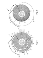
- the anti-gallop spiral represented at equilibrium in figures 1 , 3 , 6, 7 , 8, 9 and 10 and referenced as a whole 1, is formed generally of a blade 10 wound on itself in spiral, so as to have an angular elasticity.
- the central end 11 of the blade 10 is fixed in a known manner on a shell 20 driven on a balance shaft 21, while its peripheral end 12 is intended to be fixed to a not shown cock.
- the hairspring 1 comprises a plurality of turns 13, typically between 10 and 15, having between them, in equilibrium, a pitch p.
- the spiral 1 further comprises a plurality of transverse segments 15, 15 ', 15 "a, 15" b, 15 “c secured to successive turns 13, and arranged angularly to abut one on the other, when the amplitude of rotation of the hairspring 1 exceeds a determined angle ⁇ between 300 ° and 360 °, from its equilibrium position to one of its extreme positions.
- the hairspring 1 is formed, from the central end 11, of a first spiral portion 14a of connection to the ferrule 20, then of a succession of spiral portions 14 of pitch p, connected together by transverse segments 15 of length l, and finally, of a last spiral portion 14b of connection to a rooster.
- the segments 15 extend radially, but, alternatively, they may be slightly inclined relative to the radial orientation.
- the initial radius of a spiral portion 14 is equal to the final radius of a preceding portion 14 increased by the length l of a segment 15.
- the successive transverse segments 15 are arranged angularly to abut one against the other when the amplitude of the alternation associated with the contraction of the hairspring 1 reaches a determined value ⁇ of between 300 ° and 360 °.
- N is the number of turns 13 of the hairspring 1, from the central end 11 to the peripheral end 12, R n the radius of the nth turn 13, R 1 and R N , respectively the radii of the first and of the last turn 13.
- ⁇ n the angular offset at equilibrium, with respect to the radially aligned position, between the transverse segments 15 associated respectively with the nth and n + 1th turns 13, and ⁇ n the angular sector of the nth spiral portion 14.
- the transverse segments 15 abut one against the other beyond a determined rotation angle en, as shown in FIG. figure 2 .
- the turns 13 are then locked in rotation relative to each other and the hairspring 1 has no or almost no angular elasticity. Its rotation movement is suddenly blocked.
- the galloping phenomenon is thus avoided in the alternation associated with the contraction of the hairspring 1.
- This alternation will preferably be the upward alternation, since the phenomenon of galloping occurs more frequently during this alternation.
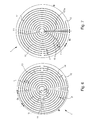
- the three spiral portions 14 are interconnected by two transverse segments 15 abutting one another when the determined angle ⁇ is reached. In this case, only two consecutive turns lock in rotation relatively to one another, thus slowing the general movement of rotation of the spring 1, instead of blocking it.
- Such a variant of the first embodiment is illustrated in figure 3 .
- the hairspring 1 can comprise two, three and up to N 'portions of spiral 14, and, respectively, three, four and up to N '+ 1 transverse segments 15, N' being a function of the number N of turns 13 and the angle ⁇ .
- the braking of the hairspring 1 increases with the number of spiral portions 14 and transverse segments 15, until complete locking of the hairspring when the number of spiral portions 14 takes the maximum value N '.
- the segments 15 extend radially slightly beyond the two spiral portions 14 that they connect, and comprise two fingers 16 and 17 at their ends, extending angularly towards the outside of the spiral portions 14 that they connect.
- the fingers 16 and 17 fit into each other when the segments 15 abut.
- the segments 15 are then locked radially relative to each other, which gives the hairspring 1, in addition to an angular rigidity, a radial rigidity, when the determined amplitude ⁇ is reached.
- the locking spiral 1 is ensured even during violent shocks, because the radial elasticity does not compensate, in this case, the angular rigidity.
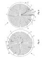
- the spiral 1 illustrated in Figures 6 and 7 differs from the embodiment described with regard to Figures 1 and 2 , in that it is formed of a single spiral portion 14, from the central end 11 to the peripheral end 12, which are secured to the transverse segments 15 'and 15 "a and 15" b.
- the transverse segments 15 ' are of length l greater than or equal to p and less than or equal to 2p, and are integral with the single spiral portion 14 by their middle. They extend substantially radially, but, alternatively, may also be slightly inclined relative to the radial orientation. In this case, the inclination must be chosen so as not to block the return to equilibrium of the hairspring 1, if the determined angle ⁇ is exceeded.
- the hairspring 1 comprises first transverse segments 15 "a and second transverse segments 15" b, integral with the single spiral portion 14 by one of their ends.
- Both are of length l greater than or equal to p / 2, less than p.
- Each turn 13 with the exception of the first and the last, has a transverse segment 15 "a and a transverse segment 15" b.
- the first turn 13 from the central end 11, has a single transverse segment 15 "oriented outwardly, while the last has only 15" b, facing inwards.
- the transverse segments 15 "a are aligned radially along a radius of the hairspring 1 and the transverse segments 15" b are offset with respect to the segments 15 "a by an angle ⁇ N.
- ⁇ NOT ⁇ R not R NOT - R 1 and the angular sector ⁇ n separating them is equal to 360 - ⁇ NOT ⁇ R not R NOT - R 1 .
- the transverse segments 15 'and 15 "a and 15" b are at least two in number, for a braking effect of the hairspring 1, and not for locking. It will also be noted that, in an advantageous variant, the segments 15 'and 15 "a, 15" b of the spiral 1 described opposite Figures 6 and 7 , comprise fingers 16 and 17 extending angularly and intended to fit into each other to give a radial rigidity spiral 1 in the angular locking position. This effect has already been described above with regard to figures 3 and 4 .
- the spiral 1 represented in figure 8 differs from the spiral 1 described next to the figure 6 , in that the transverse segments 15 'are arranged to block it when the amplitude of its rotation exceeds a critical value ⁇ in extension and not in contraction.
- the principle of operation is identical, but the rules of construction are different.
- the equilibrium angular offset ⁇ n between two transverse segments 15 'associated respectively with the nth and n + 1th turns 13, is well worth ⁇ NOT ⁇ R not R NOT - R 1 , but the angular sector ⁇ n separating them is equal to 360 + ⁇ NOT ⁇ R not R NOT - R 1 .
- the pitch p of a hairspring 1 increases, when it extends radially, by a value which depends on the amplitude of the alternation and the number N of turns 13.
- the length l of the transverse segments 15 'must then be provided for them to contact each other during the alternation associated with the extension.
- each segment 15 ' abuts against a consecutive segment 15' when the amplitude of rotation of the hairspring 1 reaches a determined angle ⁇ in extension, and the rotation of the hairspring 1 is thus blocked.
- the spiral 1 illustrated in figure 9 differs from the spiral 1 described next to the figure 6 , in that it comprises segments 15 "a and 15" c designed to block its rotation in extension and not in contraction.
- the segments 15" c point, like the transverse segments 15 “b, towards the inside of the spiral 1, but they are distinguished by their position relative to the segments 15 "a.
- the offset ⁇ n between a segment 15 "associated with an nth turn 13 and a segment 15" c associated with an n + 1 turn 13, is as before ⁇ NOT ⁇ R not R NOT - R 1 , but the angular sector ⁇ n separating them equals 360 + ⁇ NOT ⁇ R not R NOT - R 1 .
- the length l of segments 15 "a and 15" c is typically 0.8p.
- Said spiral 1 combines the characteristics of the spiral 1 represented in figure 7 and the spiral 1 shown in figure 9 . It comprises first segments 15 "a, second segments 15" b and third segments 15 “c positioned relatively to each other in the manner described previously described, the transverse segments 15" are thus aligned along a radius of the spiral 1 and the transverse segments 15 "b and 15" c are offset on either side of the segments 15 "a of an angle ⁇ n equal to ⁇ NOT ⁇ R not R NOT - R 1 .
- the segments 15 abut respectively against the segments 15" b or 15 "c.
- the spiral 1 according to the invention is made of a material having elastic properties.
- it will be chosen to manufacture silicon, by a photolithographic process well known to those skilled in the art.
- a metal spiral for example nickel, gold, or a nickel alloy and gold, obtained by a physico-chemical deposition process type liga.
Abstract
Description
La présente invention est relative à un spiral anti-galop pour un échappement d'horlogerie dépourvu de butée, du type échappement à détente.The present invention relates to an anti-gallop hairspring for a clock escapement without stop, of the type escapement trigger.
Le phénomène du galop est bien connu de l'homme de métier. Il concerne essentiellement les échappements à détente, et nuit fortement, lorsqu'il se produit, à la précision d'une pièce d'horlogerie qui en est munie.The phenomenon of galloping is well known to those skilled in the art. It mainly concerns relaxation exhausts, and strongly harms when it occurs, to the precision of a timepiece that is equipped.
Les échappements à détente sont notamment employés dans les pièces d'horlogerie de précision, car ils perturbent moins l'isochronisme de l'oscillateur que les échappements à ancre suisse. Pour une description détaillée d'un tel échappement, on se référera l'ouvrage 'Théorie de l'horlogerie', chapitre 6.7.1.. On se bornera ici à rappeler le principe du phénomène de galop dont il fait l'objet.Escapement exhausts are particularly used in precision timepieces because they disturb the isochronism of the oscillator less than the Swiss anchor escapements. For a detailed description of such an escapement, refer to the book 'Théorie de l'horlogerie', chapter 6.7.1 .. We will confine ourselves here to recalling the principle of the gallop phenomenon of which it is the object.
Dans un échappement à détente, l'oscillateur balancier-spiral oscille entre deux positions extrêmes, une position dite 'haute' et une position dite 'basse'. Chacune de ses oscillations comporte une alternance dite 'ascendante', lors de laquelle il passe de la position basse à la position haute, et une alternance dite 'descendante', lors de laquelle il passe de la position haute à la position basse. La roue d'échappement délivre à l'oscillateur balancier-spiral, une impulsion par oscillation, lors de l'alternance ascendante, dans une position dite 'd'équilibre', sensiblement à mi-chemin entre la position haute et la position basse. Lors de l'alternance descendante, le balancier-spiral ne reçoit aucune impulsion. On notera que les alternances ascendantes et descendantes sont indifféremment associées à la contraction ou à l'extension radiale du spiral.In a detent escapement, the balance-balance oscillator oscillates between two extreme positions, a so-called 'high' position and a so-called 'low' position. Each of its oscillations comprises a so-called 'ascending' alternation, during which it moves from the low position to the high position, and a so-called 'downward' alternation, during which it switches from the high position to the low position. The escape wheel delivers to the oscillator sprung-balance, an oscillation pulse, during the upward alternation, in a position called 'equilibrium', substantially halfway between the high position and the low position. During the downward alternation, the sprung balance receives no impulse. It will be noted that the ascending and descending alternations are indifferently associated with the contraction or the radial extension of the hairspring.
L'amplitude de chaque alternance, à savoir le déplacement angulaire de l'oscillateur depuis la position d'équilibre jusqu'à la position haute ou basse, est typiquement de 330°. Lors d'un choc, il arrive que le balancier-spiral reçoive un excès d'énergie et que son amplitude dépasse cette valeur, et même, excède 360°, valeur limite au-delà de laquelle, le balancier-spiral reçoit une impulsion supplémentaire. L'alternance ascendante peut alors compter deux impulsions, tandis que l'alternance descendante peut en compter une. La roue d'échappement, qui effectue normalement un pas par oscillation, effectue alors deux, voire trois pas au cours d'une même oscillation. Ce phénomène d'emballement du balancier-spiral, qui s'auto-entretient, est appelé galop. Il nuit à la précision du mouvement, car pour chaque pas supplémentaire effectué par la roue d'échappement, la mesure du temps avance d'une durée inversement proportionnelle à la fréquence d'oscillation du balancier-spiral.The amplitude of each alternation, namely the angular displacement of the oscillator from the equilibrium position to the high or low position, is typically 330 °. During an impact, the sprung balance may receive an excess of energy and its amplitude exceeds this value, and even exceeds 360 °, a limit value beyond which the sprung balance receives an impulse. additional. The upward alternation can then count two pulses, while the downward alternation can count one. The escape wheel, which normally performs a step by oscillation, then performs two or even three steps during a single oscillation. This phenomenon of runaway sprung balance, which self-maintains, is called gallop. It hinders the precision of the movement, because for each additional step made by the escape wheel, the measurement of the time advance of a duration inversely proportional to the oscillation frequency of the balance spring.
Différents mécanismes de blocage existent pour remédier au galop du balancier-spiral. Ces mécanismes visent à bloquer le mouvement de rotation du balancier-spiral au-delà d'un angle déterminé de 330° environ. L'un d'entre eux, décrit dans la demande
La présente invention propose une alternative simple et robuste aux dispositifs anti-galop existants. Elle concerne plus précisément un spiral anti-galop pour échappement d'horlogerie, destiné à osciller entre deux positions extrêmes, en passant par une position d'équilibre, et comportant une pluralité de spires. Selon l'invention, il comprend, en outre, des moyens pour bloquer au moins deux spires consécutives lorsque son amplitude de rotation depuis la position d'équilibre jusqu'à au moins l'une des positions extrêmes, atteint un angle déterminé ψ.The present invention provides a simple and robust alternative to existing anti-gallop devices. More specifically, it relates to an anti-gallop hairspring for a clock escapement, intended to oscillate between two extreme positions, passing through an equilibrium position, and comprising a plurality of turns. According to the invention, it further comprises means for locking at least two consecutive turns when its amplitude of rotation from the equilibrium position to at least one of the extreme positions reaches a determined angle ψ.
Dans un mode de réalisation avantageux, ces moyens comprennent des segments transversaux, solidaires de spires consécutives, décalés angulairement pour venir en butée l'un contre l'autre lorsque l'amplitude de rotation du spiral selon l'invention, depuis ladite position d'équilibre jusqu'à au moins l'une des positions extrêmes, atteint un angle déterminé ψ.In an advantageous embodiment, these means comprise transverse segments, integral with consecutive turns, offset angularly to abut against each other when the rotation of the spiral according to the invention, from said position of balance to at least one of the extreme positions, reaches a certain angle ψ.
Grâce à ces segments transversaux, le spiral est freiné ou bloqué dans sa rotation sans l'usage de moyens externes susceptibles de perturber son isochronisme.Thanks to these transverse segments, the hairspring is braked or blocked in its rotation without the use of external means likely to disturb its isochronism.
La présente invention concerne également un échappement d'horlogerie muni d'un tel spiral anti-galop.The present invention also relates to a clock escapement provided with such an anti-gallop spiral.
D'autres caractéristiques et avantages de la présente invention ressortiront de la description qui va suivre, faite en regard des dessins annexés, et donnant à titre d'exemple explicatif, mais nullement limitatif, quelques formes avantageuses de la réalisation d'un spiral anti-galop pour pièce d'horlogerie, dessins dans lesquels :
- les
figures 1 et 2 sont des vues de dessus d'un premier mode de réalisation d'un spiral anti-galop selon l'invention, respectivement en position d'équilibre et en position de blocage, - la
figure 3 illustre une variante de ce premier mode de réalisation d'un tel spiral, - la
figure 4 représente une forme avantageuse du premier mode de réalisation d'un spiral anti-galop selon l'invention, en position de blocage, - la
figure 5 est une vue de détail du spiral représenté enfigure 4 , - les
figures 6 et 7 sont des vues de dessus d'un deuxième et d'un troisième modes de réalisation d'un spiral anti-galop selon l'invention, configuré pour réaliser un blocage en contraction, - les
figures 8 et 9 illustrent ces mêmes deuxième et troisième modes de réalisation du spiral anti-galop selon l'invention, configuré, cette fois, pour réaliser un blocage en extension, et - la
figure 10 représente un spiral anti-galop selon l'invention réunissant les caractéristiques des modes de réalisation 7 et 9.
- the
Figures 1 and 2 are views from above of a first embodiment of an anti-galling hairspring according to the invention, respectively in the equilibrium position and in the locking position, - the
figure 3 illustrates a variant of this first embodiment of such a spiral, - the
figure 4 represents an advantageous form of the first embodiment of an anti-gallop hairspring according to the invention, in the blocking position, - the
figure 5 is a detail view of the spiral represented infigure 4 , - the
Figures 6 and 7 are views from above of a second and a third embodiment of an anti-gallop hairspring according to the invention, configured to achieve a contraction lock, - the
Figures 8 and 9 illustrate these same second and third embodiments of the anti-gallop hairspring according to the invention, configured, this time, to achieve a blockage in extension, and - the
figure 10 represents an anti-gallop hairspring according to the invention combining the features of embodiments 7 and 9.
Le spiral anti-galop représenté à l'équilibre en
Selon l'invention, le spiral 1 comporte, en outre, une pluralité de segments transversaux 15, 15', 15"a, 15"b, 15"c solidaires de spires 13 successives, et agencés angulairement pour venir buter l'un sur l'autre, lorsque l'amplitude de rotation du spiral 1 excède un angle déterminé ψ compris entre 300° et 360°, depuis sa position d'équilibre jusqu'à l'une de ses positions extrêmes.According to the invention, the spiral 1 further comprises a plurality of
Dans le mode de réalisation présenté en
A cette fin, les différents paramètres du spiral 1, dans sa position d'équilibre, sont liés par des relations géométriques explicitées ci-dessous. On note N le nombre de spires 13 du spiral 1, depuis l'extrémité centrale 11 jusqu'à l'extrémité périphérique 12, Rn le rayon de la nième spire 13, R1 et RN, les rayons respectivement de la première et de la dernière spire 13. On note encore θn le décalage angulaire à l'équilibre, par rapport à la position alignée radialement, entre les segments transversaux 15 associés respectivement aux nième et n+1ième spires 13, et Φn le secteur angulaire de la nième portion de spirale 14.To this end, the various parameters of the balance spring 1, in its equilibrium position, are linked by geometric relations explained below. N is the number of
Il est connu que l'amplitude de rotation du spiral 1, depuis sa position d'équilibre jusqu'à l'une de ses positions extrêmes, ne se répartit pas uniformément sur l'ensemble des N spires 13, les spires 13 de grand rayon absorbant une plus grande partie de l'amplitude de rotation que les spires 13 de faible rayon. On peut montrer que pour une amplitude de rotation du spiral 1 donnée, chaque spire 13 se déforme d'un angle proportionnel à son rayon Rn. Il en ressort que les segments radiaux 15, associés respectivement aux nième et n+1ième spires, sont alignés radialement lorsque l'amplitude associée à la contraction du spiral 1 prend la valeur déterminée ψ, si le décalage angulaire θn entre eux, à l'équilibre, obéit à la relation : 
Le secteur angulaire Φn d'une nième portion de spirale 14 est le complément du décalage angulaire θn entre les segments radiaux 15 associés respectivement aux nième et n+1 ième spires 13. Il obéit donc à la relation suivante : 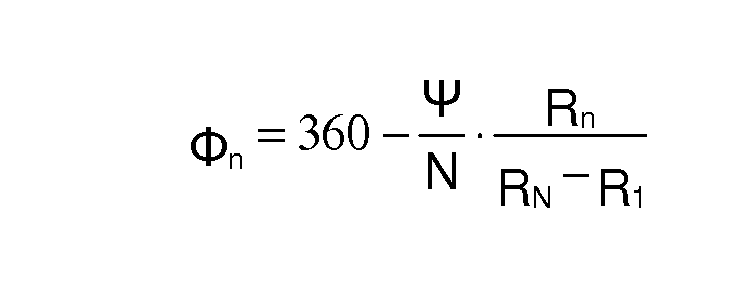
Par exemple, pour un nombre de spires égal à 10, tel qu'illustré en
Enfin, afin que deux segments 15 consécutifs viennent en butée l'un contre l'autre lorsque l'amplitude de l'alternance atteint la valeur déterminée ψ, il est nécessaire que leur longueur l soit suffisante. Comme il est connu de l'homme de métier, le pas p d'un spiral 1 diminue, lorsqu'il se contracte, d'une valeur qui dépend de l'amplitude de l'alternance et du nombre N de spires 13. Les segments 15 se contactent donc si la longueur l des segments 15 vérifie la relation : 
Lorsque les règles de construction précédentes sont appliquées, les segments transversaux 15 viennent en butée l'un contre l'autre au-delà d'un angle de rotation déterminé en contraction ψ, tel que représenté en
Il est à noter ici, qu'il peut être suffisant de freiner la rotation du spiral 1 en cas de choc, plutôt que la bloquer. Dans ce cas, le spiral 1 est formé, au minimum, d'une première portion de spirale 14a de secteur angulaire quelconque, d'une deuxième portion de spirale 14 de secteur angulaire Φn = 360 
On se réfère maintenant aux
En
Le spiral 1 illustré en
Selon la première variante représentée à l'équilibre en 

Selon la variante représentée à l'équilibre en
Chaque spire 13, à l'exception de la première et de la dernière comporte un segment transversal 15"a et un segment transversal 15"b. La première spire 13 depuis l'extrémité centrale 11, comporte un unique segment transversal 15"a orienté vers l'extérieur, tandis que la dernière n'en comporte qu'un 15"b, orienté vers l'intérieur. Les segments transversaux 15"a sont alignés radialement suivant un rayon du spiral 1 et les segments transversaux 15"b sont décalés par rapport aux segments 15"a d'un angle θn. Le décalage θn entre un segment 15"a associé à un nième spire 13 et un segment 15"b associé à une n+1ième spire 13, vaut, comme précédemment, 

Comme mentionné précédemment, les segments transversaux 15' et 15"a et 15"b sont au nombre minimum de deux, pour un effet de freinage du spiral 1, et non pas de blocage. On notera encore que, dans une variante avantageuse, les segments 15' et 15"a, 15"b du spiral 1 décrit en regard des
On a décrit précédemment des modes de réalisation d'un spiral 1 anti-galop destiné à se bloquer lors de l'alternance associée à sa contraction. Généralement, il s'agit de l'alternance positive, car le phénomène de galop se produit de préférence lors de cette alternance. Toutefois, il peut arriver que l'alternance positive soit associée à l'extension du spiral. Dans ce cas, on souhaite que le blocage du spiral ait lieu en extension et non en contraction. Les
Le spiral 1 représenté en 


Grâce à ces caractéristiques, chaque segment 15' vient en butée contre un segment 15' consécutif lorsque l'amplitude de rotation du spiral 1 atteint un angle déterminé ψ en extension, et la rotation du spiral 1 est ainsi bloquée.Thanks to these characteristics, each segment 15 'abuts against a consecutive segment 15' when the amplitude of rotation of the hairspring 1 reaches a determined angle ψ in extension, and the rotation of the hairspring 1 is thus blocked.
De la même façon, le spiral 1 illustré en 

On se réfère maintenant à la 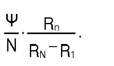
Le spiral 1 selon l'invention est fabriqué dans un matériau possédant des propriétés élastiques. De préférence, en raison de sa structure discontinue, on choisira de le fabriquer en silicium, par un procédé photolitograpique bien connu de l'homme de métier. En variante, on pourra opter pour un spiral en métal, par exemple en nickel, or, ou un alliage de nickel et or, obtenu par un procédé de dépôt physico-chimique de type liga.The spiral 1 according to the invention is made of a material having elastic properties. Preferably, because of its discontinuous structure, it will be chosen to manufacture silicon, by a photolithographic process well known to those skilled in the art. Alternatively, one can opt for a metal spiral, for example nickel, gold, or a nickel alloy and gold, obtained by a physico-chemical deposition process type liga.
Claims (19)


Priority Applications (5)
| Application Number | Priority Date | Filing Date | Title |
|---|---|---|---|
| EP10181111.5A EP2434353B1 (en) | 2010-09-28 | 2010-09-28 | Anti-tripping hairspring for timepiece escapement |
| JP2011204173A JP5372092B2 (en) | 2010-09-28 | 2011-09-20 | Hairspring with anti-trip function for watch escapement |
| US13/246,148 US8764281B2 (en) | 2010-09-28 | 2011-09-27 | Anti-trip balance-spring for a timepiece escapement |
| CN2011102950664A CN102419541B (en) | 2010-09-28 | 2011-09-27 | Anti-tripping hairspring for timepiece escapement |
| HK12110164.5A HK1169494A1 (en) | 2010-09-28 | 2012-10-15 | Anti-trip balance-spring for a timepiece escapement |
Applications Claiming Priority (1)
| Application Number | Priority Date | Filing Date | Title |
|---|---|---|---|
| EP10181111.5A EP2434353B1 (en) | 2010-09-28 | 2010-09-28 | Anti-tripping hairspring for timepiece escapement |
Publications (2)
| Publication Number | Publication Date |
|---|---|
| EP2434353A1 true EP2434353A1 (en) | 2012-03-28 |
| EP2434353B1 EP2434353B1 (en) | 2018-01-10 |
Family
ID=43643540
Family Applications (1)
| Application Number | Title | Priority Date | Filing Date |
|---|---|---|---|
| EP10181111.5A Active EP2434353B1 (en) | 2010-09-28 | 2010-09-28 | Anti-tripping hairspring for timepiece escapement |
Country Status (5)
| Country | Link |
|---|---|
| US (1) | US8764281B2 (en) |
| EP (1) | EP2434353B1 (en) |
| JP (1) | JP5372092B2 (en) |
| CN (1) | CN102419541B (en) |
| HK (1) | HK1169494A1 (en) |
Cited By (5)
| Publication number | Priority date | Publication date | Assignee | Title |
|---|---|---|---|---|
| EP2690506A1 (en) * | 2012-07-25 | 2014-01-29 | Nivarox-FAR S.A. | Anti-tripping clock hairspring |
| EP2690507A1 (en) | 2012-07-26 | 2014-01-29 | Nivarox-FAR S.A. | Holorological hairspring |
| EP2690508A1 (en) | 2012-07-26 | 2014-01-29 | Nivarox-FAR S.A. | Horological hairspring |
| EP2884347A1 (en) * | 2013-12-16 | 2015-06-17 | ETA SA Manufacture Horlogère Suisse | Hairspring with device for ensuring the separation of the turns |
| EP2908187A1 (en) | 2014-02-17 | 2015-08-19 | The Swatch Group Research and Development Ltd. | Adjustment of a clock piece resonator by changing the active length of a hairspring |
Families Citing this family (8)
| Publication number | Priority date | Publication date | Assignee | Title |
|---|---|---|---|---|
| US8562206B2 (en) * | 2010-07-12 | 2013-10-22 | Rolex S.A. | Hairspring for timepiece hairspring-balance oscillator, and method of manufacture thereof |
| EP2804054B1 (en) * | 2013-05-17 | 2020-09-23 | ETA SA Manufacture Horlogère Suisse | Anti-adhesion device of a spiral on a bridge |
| EP2884346A1 (en) * | 2013-12-16 | 2015-06-17 | ETA SA Manufacture Horlogère Suisse | Polygonal hairspring for a timepiece resonator |
| EP2908183B1 (en) * | 2014-02-14 | 2018-04-18 | ETA SA Manufacture Horlogère Suisse | Clock hairspring |
| EP3159748B1 (en) * | 2015-10-22 | 2018-12-12 | ETA SA Manufacture Horlogère Suisse | Compact hairspring with variable cross-section |
| WO2019103977A1 (en) * | 2017-11-21 | 2019-05-31 | Firehouse Horology, Inc. | Geometries for hairsprings for mechanical watches enabled by nanofabrication |
| CN110160339B (en) * | 2018-02-05 | 2020-10-23 | 嘉兴诺丁汉工业设计有限公司 | Industrial material is with mixing drying equipment based on sector gear disturbance principle |
| JP7246200B2 (en) * | 2019-02-15 | 2023-03-27 | セイコーインスツル株式会社 | Balance springs, balances, watch movements and timepieces |
Citations (3)
| Publication number | Priority date | Publication date | Assignee | Title |
|---|---|---|---|---|
| EP1431844A1 (en) * | 2002-12-19 | 2004-06-23 | SFT Services SA | Assembly for the regulating organ of a watch movement |
| EP1645918A1 (en) | 2004-10-05 | 2006-04-12 | Montres Breguet S.A. | Anti-tripping device for timepiece escapement |
| EP1801669A1 (en) | 2005-12-20 | 2007-06-27 | Montres Breguet S.A. | Device for checking the correct performance of a timepiece oscillator |
Family Cites Families (5)
| Publication number | Priority date | Publication date | Assignee | Title |
|---|---|---|---|---|
| US3696687A (en) * | 1971-03-25 | 1972-10-10 | Ametek Inc | Plastic hairspring |
| IT985551B (en) * | 1971-09-27 | 1974-12-10 | Golay Bernard Sa | TOGETHER INCLUDING A SPIRAL INTENDED TO BE APPLIED TO AN OSCILLATING ORGAN SUBJECTED TO THE ACTION OF MEANS THAT SYNCHRONIZE THE FREQUENCY WITH THAT OF A PILOT FREQUENCY |
| EP1445670A1 (en) * | 2003-02-06 | 2004-08-11 | ETA SA Manufacture Horlogère Suisse | Balance-spring resonator spiral and its method of fabrication |
| DE60333076D1 (en) * | 2003-04-29 | 2010-08-05 | Patek Philippe Sa | Balance and surface spiral spring regulator for movement |
| EP2151722B8 (en) * | 2008-07-29 | 2021-03-31 | Rolex Sa | Hairspring for balance-spring resonator |
-
2010
- 2010-09-28 EP EP10181111.5A patent/EP2434353B1/en active Active
-
2011
- 2011-09-20 JP JP2011204173A patent/JP5372092B2/en active Active
- 2011-09-27 US US13/246,148 patent/US8764281B2/en active Active
- 2011-09-27 CN CN2011102950664A patent/CN102419541B/en active Active
-
2012
- 2012-10-15 HK HK12110164.5A patent/HK1169494A1/en unknown
Patent Citations (3)
| Publication number | Priority date | Publication date | Assignee | Title |
|---|---|---|---|---|
| EP1431844A1 (en) * | 2002-12-19 | 2004-06-23 | SFT Services SA | Assembly for the regulating organ of a watch movement |
| EP1645918A1 (en) | 2004-10-05 | 2006-04-12 | Montres Breguet S.A. | Anti-tripping device for timepiece escapement |
| EP1801669A1 (en) | 2005-12-20 | 2007-06-27 | Montres Breguet S.A. | Device for checking the correct performance of a timepiece oscillator |
Cited By (15)
| Publication number | Priority date | Publication date | Assignee | Title |
|---|---|---|---|---|
| EP2690506A1 (en) * | 2012-07-25 | 2014-01-29 | Nivarox-FAR S.A. | Anti-tripping clock hairspring |
| US9016934B2 (en) | 2012-07-25 | 2015-04-28 | Nivarox—FAR S.A. | Anti-trip balance spring for a timepiece |
| WO2014016094A1 (en) | 2012-07-26 | 2014-01-30 | Nivarox-Far S.A. | Horology hairspring |
| EP2690508A1 (en) | 2012-07-26 | 2014-01-29 | Nivarox-FAR S.A. | Horological hairspring |
| CN103576528A (en) * | 2012-07-26 | 2014-02-12 | 尼瓦洛克斯-法尔股份有限公司 | Timepiece balance spring |
| US8821007B2 (en) | 2012-07-26 | 2014-09-02 | Nivarox-Far S.A. | Timepiece balance spring |
| EP2690507A1 (en) | 2012-07-26 | 2014-01-29 | Nivarox-FAR S.A. | Holorological hairspring |
| CN103576528B (en) * | 2012-07-26 | 2016-06-15 | 尼瓦洛克斯-法尔股份有限公司 | Clock and watch hairspring |
| RU2615595C2 (en) * | 2012-07-26 | 2017-04-05 | Ниварокс-Фар С.А. | Balance clock spring |
| EP2884347A1 (en) * | 2013-12-16 | 2015-06-17 | ETA SA Manufacture Horlogère Suisse | Hairspring with device for ensuring the separation of the turns |
| WO2015090815A3 (en) * | 2013-12-16 | 2015-12-10 | Eta Sa Manufacture Horlogère Suisse | Hairspring with device to prevent coils from moving close together |
| US20160299470A1 (en) * | 2013-12-16 | 2016-10-13 | Eta Sa Manufacture Horlogère Suisse | Balance spring with coil spacer device |
| US9645549B2 (en) | 2013-12-16 | 2017-05-09 | Eta Sa Manufacture Horlogere Suisse | Balance spring with coil spacer device |
| EP2908187A1 (en) | 2014-02-17 | 2015-08-19 | The Swatch Group Research and Development Ltd. | Adjustment of a clock piece resonator by changing the active length of a hairspring |
| US9354607B2 (en) | 2014-02-17 | 2016-05-31 | The Swatch Group Research And Development Ltd | Frequency regulation of a timepiece resonator via action on the active length of a balance spring |
Also Published As
| Publication number | Publication date |
|---|---|
| CN102419541B (en) | 2013-07-31 |
| EP2434353B1 (en) | 2018-01-10 |
| JP2012073248A (en) | 2012-04-12 |
| US8764281B2 (en) | 2014-07-01 |
| HK1169494A1 (en) | 2013-01-25 |
| JP5372092B2 (en) | 2013-12-18 |
| CN102419541A (en) | 2012-04-18 |
| US20120075963A1 (en) | 2012-03-29 |
Similar Documents
| Publication | Publication Date | Title |
|---|---|---|
| EP2434353B1 (en) | Anti-tripping hairspring for timepiece escapement | |
| EP1736838B1 (en) | Timepiece | |
| EP2998800B1 (en) | Timepiece component with flexible pivot | |
| EP3182213B1 (en) | Mechanism for adjusting an average speed in a clock movement and clock movement | |
| EP2199875B1 (en) | Detent escapement | |
| EP3001257B1 (en) | Paraxial, isochronous timepiece resonator | |
| EP2290476B1 (en) | Isochronism corrector for a timepiece escapement and an escapement equipped with such a corrector | |
| EP2613206A1 (en) | Hairspring with two spiral springs with improved isochronism | |
| EP2405312A1 (en) | Balance hairspring with two levels and immobile mass centre | |
| EP3037894B1 (en) | Mechanism and method for adjusting a speed in a watch movement | |
| EP3430478B1 (en) | Mechanism for a timepiece and timepiece comprising such a mechanism | |
| EP2859411B1 (en) | Escapement device for timepiece | |
| WO2013092316A1 (en) | Escapement mechanism | |
| EP2677372B1 (en) | Wheel with clearance compensation | |
| EP2613205A2 (en) | Regulating mechanism for watch or chronograph | |
| CH703833A2 (en) | Anti-tripping hairspring for detent type timepiece escapement, has blocking units for blocking consecutive spiral-turns when rotation amplitude of hairspring from balance position to extreme position reaches determined angle | |
| CH717182B1 (en) | Timepiece movement comprising a mechanical oscillator and a device for stopping said oscillator. | |
| WO2017102917A1 (en) | Mechanical oscillator for timepiece, adjustment mechanism including said mechanical oscillator, and clock movement | |
| EP3451073B1 (en) | Timepiece oscillator having flexible guides with wide angular travel | |
| EP3619579B1 (en) | Clock device with positioning member | |
| CH705300B1 (en) | Wheel exhaust. | |
| CH715589B1 (en) | Escapement with rubbing rest. | |
| EP3707563A1 (en) | Driving member of a timepiece | |
| EP2802941B1 (en) | Regulating member for a mechanical chronograph | |
| EP3475763B1 (en) | Clock escapement |
Legal Events
| Date | Code | Title | Description |
|---|---|---|---|
| PUAI | Public reference made under article 153(3) epc to a published international application that has entered the european phase |
Free format text: ORIGINAL CODE: 0009012 |
|
| AK | Designated contracting states |
Kind code of ref document: A1 Designated state(s): AL AT BE BG CH CY CZ DE DK EE ES FI FR GB GR HR HU IE IS IT LI LT LU LV MC MK MT NL NO PL PT RO SE SI SK SM TR |
|
| AX | Request for extension of the european patent |
Extension state: BA ME RS |
|
| 17P | Request for examination filed |
Effective date: 20120928 |
|
| 17Q | First examination report despatched |
Effective date: 20170220 |
|
| GRAP | Despatch of communication of intention to grant a patent |
Free format text: ORIGINAL CODE: EPIDOSNIGR1 |
|
| INTG | Intention to grant announced |
Effective date: 20170901 |
|
| GRAS | Grant fee paid |
Free format text: ORIGINAL CODE: EPIDOSNIGR3 |
|
| GRAA | (expected) grant |
Free format text: ORIGINAL CODE: 0009210 |
|
| AK | Designated contracting states |
Kind code of ref document: B1 Designated state(s): AL AT BE BG CH CY CZ DE DK EE ES FI FR GB GR HR HU IE IS IT LI LT LU LV MC MK MT NL NO PL PT RO SE SI SK SM TR |
|
| REG | Reference to a national code |
Ref country code: GB Ref legal event code: FG4D Free format text: NOT ENGLISH |
|
| REG | Reference to a national code |
Ref country code: CH Ref legal event code: EP Ref country code: CH Ref legal event code: NV Representative=s name: ICB INGENIEURS CONSEILS EN BREVETS SA, CH Ref country code: AT Ref legal event code: REF Ref document number: 963043 Country of ref document: AT Kind code of ref document: T Effective date: 20180115 |
|
| REG | Reference to a national code |
Ref country code: IE Ref legal event code: FG4D Free format text: LANGUAGE OF EP DOCUMENT: FRENCH |
|
| REG | Reference to a national code |
Ref country code: DE Ref legal event code: R096 Ref document number: 602010047899 Country of ref document: DE |
|
| REG | Reference to a national code |
Ref country code: NL Ref legal event code: MP Effective date: 20180110 |
|
| REG | Reference to a national code |
Ref country code: AT Ref legal event code: MK05 Ref document number: 963043 Country of ref document: AT Kind code of ref document: T Effective date: 20180110 |
|
| PG25 | Lapsed in a contracting state [announced via postgrant information from national office to epo] |
Ref country code: NL Free format text: LAPSE BECAUSE OF FAILURE TO SUBMIT A TRANSLATION OF THE DESCRIPTION OR TO PAY THE FEE WITHIN THE PRESCRIBED TIME-LIMIT Effective date: 20180110 |
|
| PG25 | Lapsed in a contracting state [announced via postgrant information from national office to epo] |
Ref country code: LT Free format text: LAPSE BECAUSE OF FAILURE TO SUBMIT A TRANSLATION OF THE DESCRIPTION OR TO PAY THE FEE WITHIN THE PRESCRIBED TIME-LIMIT Effective date: 20180110 Ref country code: FI Free format text: LAPSE BECAUSE OF FAILURE TO SUBMIT A TRANSLATION OF THE DESCRIPTION OR TO PAY THE FEE WITHIN THE PRESCRIBED TIME-LIMIT Effective date: 20180110 Ref country code: CY Free format text: LAPSE BECAUSE OF FAILURE TO SUBMIT A TRANSLATION OF THE DESCRIPTION OR TO PAY THE FEE WITHIN THE PRESCRIBED TIME-LIMIT Effective date: 20180110 Ref country code: ES Free format text: LAPSE BECAUSE OF FAILURE TO SUBMIT A TRANSLATION OF THE DESCRIPTION OR TO PAY THE FEE WITHIN THE PRESCRIBED TIME-LIMIT Effective date: 20180110 Ref country code: HR Free format text: LAPSE BECAUSE OF FAILURE TO SUBMIT A TRANSLATION OF THE DESCRIPTION OR TO PAY THE FEE WITHIN THE PRESCRIBED TIME-LIMIT Effective date: 20180110 Ref country code: NO Free format text: LAPSE BECAUSE OF FAILURE TO SUBMIT A TRANSLATION OF THE DESCRIPTION OR TO PAY THE FEE WITHIN THE PRESCRIBED TIME-LIMIT Effective date: 20180410 |
|
| REG | Reference to a national code |
Ref country code: FR Ref legal event code: PLFP Year of fee payment: 9 |
|
| PG25 | Lapsed in a contracting state [announced via postgrant information from national office to epo] |
Ref country code: PL Free format text: LAPSE BECAUSE OF FAILURE TO SUBMIT A TRANSLATION OF THE DESCRIPTION OR TO PAY THE FEE WITHIN THE PRESCRIBED TIME-LIMIT Effective date: 20180110 Ref country code: BG Free format text: LAPSE BECAUSE OF FAILURE TO SUBMIT A TRANSLATION OF THE DESCRIPTION OR TO PAY THE FEE WITHIN THE PRESCRIBED TIME-LIMIT Effective date: 20180410 Ref country code: AT Free format text: LAPSE BECAUSE OF FAILURE TO SUBMIT A TRANSLATION OF THE DESCRIPTION OR TO PAY THE FEE WITHIN THE PRESCRIBED TIME-LIMIT Effective date: 20180110 Ref country code: LV Free format text: LAPSE BECAUSE OF FAILURE TO SUBMIT A TRANSLATION OF THE DESCRIPTION OR TO PAY THE FEE WITHIN THE PRESCRIBED TIME-LIMIT Effective date: 20180110 Ref country code: SE Free format text: LAPSE BECAUSE OF FAILURE TO SUBMIT A TRANSLATION OF THE DESCRIPTION OR TO PAY THE FEE WITHIN THE PRESCRIBED TIME-LIMIT Effective date: 20180110 Ref country code: GR Free format text: LAPSE BECAUSE OF FAILURE TO SUBMIT A TRANSLATION OF THE DESCRIPTION OR TO PAY THE FEE WITHIN THE PRESCRIBED TIME-LIMIT Effective date: 20180411 Ref country code: IS Free format text: LAPSE BECAUSE OF FAILURE TO SUBMIT A TRANSLATION OF THE DESCRIPTION OR TO PAY THE FEE WITHIN THE PRESCRIBED TIME-LIMIT Effective date: 20180510 |
|
| PG25 | Lapsed in a contracting state [announced via postgrant information from national office to epo] |
Ref country code: MT Free format text: LAPSE BECAUSE OF FAILURE TO SUBMIT A TRANSLATION OF THE DESCRIPTION OR TO PAY THE FEE WITHIN THE PRESCRIBED TIME-LIMIT Effective date: 20180110 |
|
| REG | Reference to a national code |
Ref country code: DE Ref legal event code: R097 Ref document number: 602010047899 Country of ref document: DE |
|
| PG25 | Lapsed in a contracting state [announced via postgrant information from national office to epo] |
Ref country code: RO Free format text: LAPSE BECAUSE OF FAILURE TO SUBMIT A TRANSLATION OF THE DESCRIPTION OR TO PAY THE FEE WITHIN THE PRESCRIBED TIME-LIMIT Effective date: 20180110 Ref country code: IT Free format text: LAPSE BECAUSE OF FAILURE TO SUBMIT A TRANSLATION OF THE DESCRIPTION OR TO PAY THE FEE WITHIN THE PRESCRIBED TIME-LIMIT Effective date: 20180110 Ref country code: AL Free format text: LAPSE BECAUSE OF FAILURE TO SUBMIT A TRANSLATION OF THE DESCRIPTION OR TO PAY THE FEE WITHIN THE PRESCRIBED TIME-LIMIT Effective date: 20180110 Ref country code: EE Free format text: LAPSE BECAUSE OF FAILURE TO SUBMIT A TRANSLATION OF THE DESCRIPTION OR TO PAY THE FEE WITHIN THE PRESCRIBED TIME-LIMIT Effective date: 20180110 |
|
| PLBE | No opposition filed within time limit |
Free format text: ORIGINAL CODE: 0009261 |
|
| STAA | Information on the status of an ep patent application or granted ep patent |
Free format text: STATUS: NO OPPOSITION FILED WITHIN TIME LIMIT |
|
| PG25 | Lapsed in a contracting state [announced via postgrant information from national office to epo] |
Ref country code: CZ Free format text: LAPSE BECAUSE OF FAILURE TO SUBMIT A TRANSLATION OF THE DESCRIPTION OR TO PAY THE FEE WITHIN THE PRESCRIBED TIME-LIMIT Effective date: 20180110 Ref country code: SK Free format text: LAPSE BECAUSE OF FAILURE TO SUBMIT A TRANSLATION OF THE DESCRIPTION OR TO PAY THE FEE WITHIN THE PRESCRIBED TIME-LIMIT Effective date: 20180110 Ref country code: SM Free format text: LAPSE BECAUSE OF FAILURE TO SUBMIT A TRANSLATION OF THE DESCRIPTION OR TO PAY THE FEE WITHIN THE PRESCRIBED TIME-LIMIT Effective date: 20180110 Ref country code: DK Free format text: LAPSE BECAUSE OF FAILURE TO SUBMIT A TRANSLATION OF THE DESCRIPTION OR TO PAY THE FEE WITHIN THE PRESCRIBED TIME-LIMIT Effective date: 20180110 |
|
| 26N | No opposition filed |
Effective date: 20181011 |
|
| PG25 | Lapsed in a contracting state [announced via postgrant information from national office to epo] |
Ref country code: SI Free format text: LAPSE BECAUSE OF FAILURE TO SUBMIT A TRANSLATION OF THE DESCRIPTION OR TO PAY THE FEE WITHIN THE PRESCRIBED TIME-LIMIT Effective date: 20180110 |
|
| PG25 | Lapsed in a contracting state [announced via postgrant information from national office to epo] |
Ref country code: MC Free format text: LAPSE BECAUSE OF FAILURE TO SUBMIT A TRANSLATION OF THE DESCRIPTION OR TO PAY THE FEE WITHIN THE PRESCRIBED TIME-LIMIT Effective date: 20180110 |
|
| REG | Reference to a national code |
Ref country code: BE Ref legal event code: MM Effective date: 20180930 |
|
| REG | Reference to a national code |
Ref country code: IE Ref legal event code: MM4A |
|
| PG25 | Lapsed in a contracting state [announced via postgrant information from national office to epo] |
Ref country code: LU Free format text: LAPSE BECAUSE OF NON-PAYMENT OF DUE FEES Effective date: 20180928 |
|
| PG25 | Lapsed in a contracting state [announced via postgrant information from national office to epo] |
Ref country code: IE Free format text: LAPSE BECAUSE OF NON-PAYMENT OF DUE FEES Effective date: 20180928 |
|
| PG25 | Lapsed in a contracting state [announced via postgrant information from national office to epo] |
Ref country code: BE Free format text: LAPSE BECAUSE OF NON-PAYMENT OF DUE FEES Effective date: 20180930 |
|
| PG25 | Lapsed in a contracting state [announced via postgrant information from national office to epo] |
Ref country code: TR Free format text: LAPSE BECAUSE OF FAILURE TO SUBMIT A TRANSLATION OF THE DESCRIPTION OR TO PAY THE FEE WITHIN THE PRESCRIBED TIME-LIMIT Effective date: 20180110 |
|
| PG25 | Lapsed in a contracting state [announced via postgrant information from national office to epo] |
Ref country code: PT Free format text: LAPSE BECAUSE OF FAILURE TO SUBMIT A TRANSLATION OF THE DESCRIPTION OR TO PAY THE FEE WITHIN THE PRESCRIBED TIME-LIMIT Effective date: 20180110 Ref country code: HU Free format text: LAPSE BECAUSE OF FAILURE TO SUBMIT A TRANSLATION OF THE DESCRIPTION OR TO PAY THE FEE WITHIN THE PRESCRIBED TIME-LIMIT; INVALID AB INITIO Effective date: 20100928 |
|
| PG25 | Lapsed in a contracting state [announced via postgrant information from national office to epo] |
Ref country code: MK Free format text: LAPSE BECAUSE OF NON-PAYMENT OF DUE FEES Effective date: 20180110 |
|
| P01 | Opt-out of the competence of the unified patent court (upc) registered |
Effective date: 20230611 |
|
| PGFP | Annual fee paid to national office [announced via postgrant information from national office to epo] |
Ref country code: GB Payment date: 20230823 Year of fee payment: 14 |
|
| PGFP | Annual fee paid to national office [announced via postgrant information from national office to epo] |
Ref country code: FR Payment date: 20230822 Year of fee payment: 14 Ref country code: DE Payment date: 20230822 Year of fee payment: 14 |
|
| PGFP | Annual fee paid to national office [announced via postgrant information from national office to epo] |
Ref country code: CH Payment date: 20231001 Year of fee payment: 14 |