EP2433840A1 - Bewegungssteuereinheit für ein Fahrzeug basierend auf Ruckinformation - Google Patents
Bewegungssteuereinheit für ein Fahrzeug basierend auf Ruckinformation Download PDFInfo
- Publication number
- EP2433840A1 EP2433840A1 EP11184288A EP11184288A EP2433840A1 EP 2433840 A1 EP2433840 A1 EP 2433840A1 EP 11184288 A EP11184288 A EP 11184288A EP 11184288 A EP11184288 A EP 11184288A EP 2433840 A1 EP2433840 A1 EP 2433840A1
- Authority
- EP
- European Patent Office
- Prior art keywords
- vehicle
- yaw moment
- acceleration
- lateral
- dot
- Prior art date
- Legal status (The legal status is an assumption and is not a legal conclusion. Google has not performed a legal analysis and makes no representation as to the accuracy of the status listed.)
- Granted
Links
Images


Classifications
-
- B—PERFORMING OPERATIONS; TRANSPORTING
- B60—VEHICLES IN GENERAL
- B60W—CONJOINT CONTROL OF VEHICLE SUB-UNITS OF DIFFERENT TYPE OR DIFFERENT FUNCTION; CONTROL SYSTEMS SPECIALLY ADAPTED FOR HYBRID VEHICLES; ROAD VEHICLE DRIVE CONTROL SYSTEMS FOR PURPOSES NOT RELATED TO THE CONTROL OF A PARTICULAR SUB-UNIT
- B60W40/00—Estimation or calculation of non-directly measurable driving parameters for road vehicle drive control systems not related to the control of a particular sub unit, e.g. by using mathematical models
- B60W40/02—Estimation or calculation of non-directly measurable driving parameters for road vehicle drive control systems not related to the control of a particular sub unit, e.g. by using mathematical models related to ambient conditions
- B60W40/06—Road conditions
- B60W40/064—Degree of grip
-
- B—PERFORMING OPERATIONS; TRANSPORTING
- B60—VEHICLES IN GENERAL
- B60W—CONJOINT CONTROL OF VEHICLE SUB-UNITS OF DIFFERENT TYPE OR DIFFERENT FUNCTION; CONTROL SYSTEMS SPECIALLY ADAPTED FOR HYBRID VEHICLES; ROAD VEHICLE DRIVE CONTROL SYSTEMS FOR PURPOSES NOT RELATED TO THE CONTROL OF A PARTICULAR SUB-UNIT
- B60W30/00—Purposes of road vehicle drive control systems not related to the control of a particular sub-unit, e.g. of systems using conjoint control of vehicle sub-units, or advanced driver assistance systems for ensuring comfort, stability and safety or drive control systems for propelling or retarding the vehicle
- B60W30/02—Control of vehicle driving stability
-
- B—PERFORMING OPERATIONS; TRANSPORTING
- B60—VEHICLES IN GENERAL
- B60T—VEHICLE BRAKE CONTROL SYSTEMS OR PARTS THEREOF; BRAKE CONTROL SYSTEMS OR PARTS THEREOF, IN GENERAL; ARRANGEMENT OF BRAKING ELEMENTS ON VEHICLES IN GENERAL; PORTABLE DEVICES FOR PREVENTING UNWANTED MOVEMENT OF VEHICLES; VEHICLE MODIFICATIONS TO FACILITATE COOLING OF BRAKES
- B60T8/00—Arrangements for adjusting wheel-braking force to meet varying vehicular or ground-surface conditions, e.g. limiting or varying distribution of braking force
- B60T8/17—Using electrical or electronic regulation means to control braking
- B60T8/1755—Brake regulation specially adapted to control the stability of the vehicle, e.g. taking into account yaw rate or transverse acceleration in a curve
-
- B—PERFORMING OPERATIONS; TRANSPORTING
- B60—VEHICLES IN GENERAL
- B60W—CONJOINT CONTROL OF VEHICLE SUB-UNITS OF DIFFERENT TYPE OR DIFFERENT FUNCTION; CONTROL SYSTEMS SPECIALLY ADAPTED FOR HYBRID VEHICLES; ROAD VEHICLE DRIVE CONTROL SYSTEMS FOR PURPOSES NOT RELATED TO THE CONTROL OF A PARTICULAR SUB-UNIT
- B60W30/00—Purposes of road vehicle drive control systems not related to the control of a particular sub-unit, e.g. of systems using conjoint control of vehicle sub-units, or advanced driver assistance systems for ensuring comfort, stability and safety or drive control systems for propelling or retarding the vehicle
- B60W30/02—Control of vehicle driving stability
- B60W30/045—Improving turning performance
-
- B—PERFORMING OPERATIONS; TRANSPORTING
- B60—VEHICLES IN GENERAL
- B60W—CONJOINT CONTROL OF VEHICLE SUB-UNITS OF DIFFERENT TYPE OR DIFFERENT FUNCTION; CONTROL SYSTEMS SPECIALLY ADAPTED FOR HYBRID VEHICLES; ROAD VEHICLE DRIVE CONTROL SYSTEMS FOR PURPOSES NOT RELATED TO THE CONTROL OF A PARTICULAR SUB-UNIT
- B60W30/00—Purposes of road vehicle drive control systems not related to the control of a particular sub-unit, e.g. of systems using conjoint control of vehicle sub-units, or advanced driver assistance systems for ensuring comfort, stability and safety or drive control systems for propelling or retarding the vehicle
- B60W30/18—Propelling the vehicle
- B60W30/18009—Propelling the vehicle related to particular drive situations
- B60W30/18145—Cornering
-
- B—PERFORMING OPERATIONS; TRANSPORTING
- B60—VEHICLES IN GENERAL
- B60W—CONJOINT CONTROL OF VEHICLE SUB-UNITS OF DIFFERENT TYPE OR DIFFERENT FUNCTION; CONTROL SYSTEMS SPECIALLY ADAPTED FOR HYBRID VEHICLES; ROAD VEHICLE DRIVE CONTROL SYSTEMS FOR PURPOSES NOT RELATED TO THE CONTROL OF A PARTICULAR SUB-UNIT
- B60W40/00—Estimation or calculation of non-directly measurable driving parameters for road vehicle drive control systems not related to the control of a particular sub unit, e.g. by using mathematical models
- B60W40/10—Estimation or calculation of non-directly measurable driving parameters for road vehicle drive control systems not related to the control of a particular sub unit, e.g. by using mathematical models related to vehicle motion
- B60W40/103—Side slip angle of vehicle body
-
- B—PERFORMING OPERATIONS; TRANSPORTING
- B60—VEHICLES IN GENERAL
- B60W—CONJOINT CONTROL OF VEHICLE SUB-UNITS OF DIFFERENT TYPE OR DIFFERENT FUNCTION; CONTROL SYSTEMS SPECIALLY ADAPTED FOR HYBRID VEHICLES; ROAD VEHICLE DRIVE CONTROL SYSTEMS FOR PURPOSES NOT RELATED TO THE CONTROL OF A PARTICULAR SUB-UNIT
- B60W40/00—Estimation or calculation of non-directly measurable driving parameters for road vehicle drive control systems not related to the control of a particular sub unit, e.g. by using mathematical models
- B60W40/10—Estimation or calculation of non-directly measurable driving parameters for road vehicle drive control systems not related to the control of a particular sub unit, e.g. by using mathematical models related to vehicle motion
- B60W40/114—Yaw movement
-
- B—PERFORMING OPERATIONS; TRANSPORTING
- B60—VEHICLES IN GENERAL
- B60T—VEHICLE BRAKE CONTROL SYSTEMS OR PARTS THEREOF; BRAKE CONTROL SYSTEMS OR PARTS THEREOF, IN GENERAL; ARRANGEMENT OF BRAKING ELEMENTS ON VEHICLES IN GENERAL; PORTABLE DEVICES FOR PREVENTING UNWANTED MOVEMENT OF VEHICLES; VEHICLE MODIFICATIONS TO FACILITATE COOLING OF BRAKES
- B60T2230/00—Monitoring, detecting special vehicle behaviour; Counteracting thereof
- B60T2230/02—Side slip angle, attitude angle, floating angle, drift angle
-
- B—PERFORMING OPERATIONS; TRANSPORTING
- B60—VEHICLES IN GENERAL
- B60T—VEHICLE BRAKE CONTROL SYSTEMS OR PARTS THEREOF; BRAKE CONTROL SYSTEMS OR PARTS THEREOF, IN GENERAL; ARRANGEMENT OF BRAKING ELEMENTS ON VEHICLES IN GENERAL; PORTABLE DEVICES FOR PREVENTING UNWANTED MOVEMENT OF VEHICLES; VEHICLE MODIFICATIONS TO FACILITATE COOLING OF BRAKES
- B60T2230/00—Monitoring, detecting special vehicle behaviour; Counteracting thereof
- B60T2230/04—Jerk, soft-stop; Anti-jerk, reduction of pitch or nose-dive when braking
-
- B—PERFORMING OPERATIONS; TRANSPORTING
- B60—VEHICLES IN GENERAL
- B60W—CONJOINT CONTROL OF VEHICLE SUB-UNITS OF DIFFERENT TYPE OR DIFFERENT FUNCTION; CONTROL SYSTEMS SPECIALLY ADAPTED FOR HYBRID VEHICLES; ROAD VEHICLE DRIVE CONTROL SYSTEMS FOR PURPOSES NOT RELATED TO THE CONTROL OF A PARTICULAR SUB-UNIT
- B60W2520/00—Input parameters relating to overall vehicle dynamics
- B60W2520/10—Longitudinal speed
-
- B—PERFORMING OPERATIONS; TRANSPORTING
- B60—VEHICLES IN GENERAL
- B60W—CONJOINT CONTROL OF VEHICLE SUB-UNITS OF DIFFERENT TYPE OR DIFFERENT FUNCTION; CONTROL SYSTEMS SPECIALLY ADAPTED FOR HYBRID VEHICLES; ROAD VEHICLE DRIVE CONTROL SYSTEMS FOR PURPOSES NOT RELATED TO THE CONTROL OF A PARTICULAR SUB-UNIT
- B60W2520/00—Input parameters relating to overall vehicle dynamics
- B60W2520/12—Lateral speed
- B60W2520/125—Lateral acceleration
-
- B—PERFORMING OPERATIONS; TRANSPORTING
- B60—VEHICLES IN GENERAL
- B60W—CONJOINT CONTROL OF VEHICLE SUB-UNITS OF DIFFERENT TYPE OR DIFFERENT FUNCTION; CONTROL SYSTEMS SPECIALLY ADAPTED FOR HYBRID VEHICLES; ROAD VEHICLE DRIVE CONTROL SYSTEMS FOR PURPOSES NOT RELATED TO THE CONTROL OF A PARTICULAR SUB-UNIT
- B60W2520/00—Input parameters relating to overall vehicle dynamics
- B60W2520/14—Yaw
-
- B—PERFORMING OPERATIONS; TRANSPORTING
- B60—VEHICLES IN GENERAL
- B60W—CONJOINT CONTROL OF VEHICLE SUB-UNITS OF DIFFERENT TYPE OR DIFFERENT FUNCTION; CONTROL SYSTEMS SPECIALLY ADAPTED FOR HYBRID VEHICLES; ROAD VEHICLE DRIVE CONTROL SYSTEMS FOR PURPOSES NOT RELATED TO THE CONTROL OF A PARTICULAR SUB-UNIT
- B60W2520/00—Input parameters relating to overall vehicle dynamics
- B60W2520/28—Wheel speed
-
- B—PERFORMING OPERATIONS; TRANSPORTING
- B60—VEHICLES IN GENERAL
- B60W—CONJOINT CONTROL OF VEHICLE SUB-UNITS OF DIFFERENT TYPE OR DIFFERENT FUNCTION; CONTROL SYSTEMS SPECIALLY ADAPTED FOR HYBRID VEHICLES; ROAD VEHICLE DRIVE CONTROL SYSTEMS FOR PURPOSES NOT RELATED TO THE CONTROL OF A PARTICULAR SUB-UNIT
- B60W2720/00—Output or target parameters relating to overall vehicle dynamics
- B60W2720/14—Yaw
Definitions
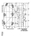
- Figs. 2A to 2D are schematic views illustrating a state where three types of positive yaw moment inputs are carried out when a vehicle turns in a counterclockwise direction.
- Figs. 3A to 3D are schematic views illustrating a state where three types of negative yaw moment inputs are carried out when a vehicle turns in a counterclockwise direction.
- Figs. 2A to 2D are views illustrating three methods upon inputting the positive yaw moment from the standard state shown in Fig. 2A .
- a lateral motion equation and a yawing (rotation) motion equation of the vehicle 0 in the standard state shown in Fig. 2A are expressed.
- m a mass of the vehicle
- Gy a lateral acceleration applied to the vehicle
- Fyf a lateral force of the two front wheels
- Fyr a lateral force of the two rear wheels
- M a yaw moment
- Iz a yawing inertia moment of the vehicle
- r_dot a yaw angular acceleration of the vehicle 0 (r denotes a yaw rate)
- Fig. 2B is a state where 'Yaw Moment Addition in terms of Steering Operation' is carried out from the standard state shown in Fig. 2A . Since the front wheel steering angle increases by ⁇ f and the rear wheel steering angle increases by ⁇ r compared with the steady state cornering shown in Fig. 2A , the lateral force of the two front wheels increases from Fyf to Fysf and the lateral force of the two rear wheels decreases from Fyr to Fyrf, and according to Equation 2, the positive moment (Ms) is generated as the following Equation 3.
- the positive moment can be generated from a general front wheel steering vehicle.
- Fig. 2C is a state where 'Yaw Moment Addition in terms of Left and Right Differential Brake and Drive Input' is carried out from the standard state shown in Fig. 2A , in which a brake force -Fdrl is applied to the left rear wheel 63, a drive force Fdrr is applied to the right rear wheel 64, and a brake force -Fdf is applied to the left front wheel 61.
- M d F yf ⁇ l f - F yr ⁇ l r + d 2 ⁇ F drl + F drr + F df > 0
- d denotes a tread (distance between the left and right vehicle wheels as shown in the drawing).
- F drl + F drr + F df 0
- the yaw moment can be generated without generating the longitudinal acceleration or deceleration other than the front wheel driven vehicle (in this example, without driving the right front wheel 62). That is, the yaw moment can be added without giving an unpleasant feeling to the driver.
- Fig. 2D is a method in which a vertical load transfer is positively generated from the rear wheel to the front wheel by applying the brake force and an original restoration yaw moment of the vehicle reduces, thereby generating the yaw moment.
- the phenomenon of the yaw moment addition in terms of the vertical load transfer is such that the yaw moment due to the acceleration or deceleration during a steady state cornering action is proportional to a value obtained by multiplying the lateral force by the longitudinal acceleration within a range in which the lateral force of the tire is proportional to the vertical load as disclosed in p.54 to 60 of 'Improvement of Vehicle Motion Performance in terms of Yaw Moment Control' written by SHIBAHATA et al.
- Figs. 3A to 3D are methods in which the negative yaw moment is input in the same way as those shown in Figs. 2A to 2D .
- the detailed description is omitted because the method is the same as that of the positive yaw moment input method shown in Figs. 2A to 2D , the moment in the restoration direction (clockwise direction shown in Figs.
- 3B , 3C, and 3D is obtained in such a manner that the steering operation is carried out so that the steering angle decreases or the steering operation is carried out so that a phase of the rear wheel becomes the same as that of the front wheel, the brake or drive operation is carried out so that an inverse brake or drive force is applied, the load movement is carried out so that an acceleration is performed to increase a load of the rear wheel, the lateral force of the rear wheel comparatively increases, and the lateral force of the front wheel decreases.
- the vehicle according to this embodiment can generate both the positive and negative yaw moment on the basis of the command of the central controller 40.
- this corresponds to a state where the vehicle turns along a certain curve.
- C(s) (X(s), Y(s)) of the coordinate system (X, Y) fixed to a ground
- s denotes a distance along the curve.
- ⁇ 1/ ⁇ (p: turning radius)
- ⁇ is shown by using an arc length parameter (s) along the locus as shown in Equation 8.
- a locus of the vehicle when a handle is steered at a stable angular velocity during a stable vehicle velocity is called a clothoid curve which is often used for designing a road.
- a time variation of the curvature of the vehicle becomes stable (which may be supposed that the arc length parameter changes to the time parameter t).
- ⁇ (s) is expressed by Equation 12.
- the state without a variation in sideslip indicates a state where a difference between a vector (V) in a direction perpendicular to the curve (bold black curve indicating C(s)) and a vehicle velocity direction (direction indicated by the dashed line) is zero ( Fig. 5A ) or a state where an angle ( ⁇ ) called a sideslip angle is stable ( Fig. 5B ), which is considered as an ideal state where a revolution and a rotation of the vehicle cooperatively correspond to each other.
- the yaw angle generated in the ideal state is determined geometrically and is not directly involved with the vehicle dynamics.
- the details shown in Figs. 5A to 5B are described in, for example, 'Vehicle dynamics and control' written by ABE Masato and published by Sankaido, First edition, July 10, 1992, Third chapter .
- Gy_dot denotes the lateral jerk of the vehicle.
- Equation 20 shows the yaw angular acceleration necessary for the vehicle moving in the ideal state.
- the reference moment indicates a moment necessary for moving along the path in a state where the revolution and the rotation of the vehicle are cooperatively correspond to each other as shown in Figs. 5A to 5B .
- the moment is large, the vehicle to obtain the yaw moment acting on the current vehicle.
- k denotes a proportional gain.
- Fig. 7 is a schematic view illustrating the configuration of the control logic according to this embodiment.
- the yaw moment of the vehicle is configured to be controlled on the basis of a value (Gy_dot/V) obtained by dividing the lateral jerk Gy_dot of the vehicle by the longitudinal velocity (V) of the vehicle.
- the yaw moment of the vehicle is configured to be controlled so that a difference between (Gy_dot/V) and (r_dot) becomes small by detecting the yaw angular acceleration (r_dot) of the vehicle.
- an open loop control particularly, the yaw moment control in terms of the vertical load transfer is adopted.
- the yaw moment (Mzls) due to the acceleration or deceleration during a steady state cornering action is proportional to a value obtained by the lateral acceleration by the longitudinal acceleration as shown in Equation 22.
- m denotes a vehicle mass
- h denotes a height of gravity center point
- g denotes a gravity acceleration.
- M zls - mh g ⁇ G x ⁇ G y
- the longitudinal acceleration realizing the control moment having the same profile as that of the necessary yaw moment is obtained.
- This may be regarded as an overall control of longitudinal motion and lateral motion which determines the lateral acceleration generated by the steering operation and the longitudinal acceleration by the brake and accelerator operation in accordance with the lateral acceleration.
- a command longitudinal acceleration Gxc is expressed as the following Equation 23.
- the lateral acceleration becomes a small value and the command longitudinal acceleration Gxc becomes a large value.
- Equation 24 it is sufficiently effective in practical engineering even when the command longitudinal acceleration Gxc is determined in such a manner that main information is obtained from the lateral jerk (Gy_dot) of the vehicle and other information is obtained from the velocity, the lateral acceleration or the function f(Gy, V) thereof, or dependent information and a gain KGyV stored in a map etc.
- means for detecting the longitudinal velocity (V) of the vehicle and the lateral jerk (Gy_dot) of the vehicle and the longitudinal acceleration of the vehicle is controlled on the basis of the value (Gy_dot/V) obtained by dividing the lateral jerk (Gy_dot) of the vehicle by the longitudinal velocity (V) of the vehicle so that the yaw moment of the vehicle is controlled in terms of the vertical load transfer. More specifically, the
Priority Applications (1)
| Application Number | Priority Date | Filing Date | Title |
|---|---|---|---|
| EP13161910.8A EP2626264B1 (de) | 2007-05-18 | 2008-05-15 | Bewegungssteuersystem für ein Fahrzeug basierend auf Ruckinformation |
Applications Claiming Priority (2)
| Application Number | Priority Date | Filing Date | Title |
|---|---|---|---|
| JP2007132987A JP4568302B2 (ja) | 2007-05-18 | 2007-05-18 | 加加速度情報を用いた車両の前後加速度制御装置 |
| EP08009005A EP1992537B1 (de) | 2007-05-18 | 2008-05-15 | Bewegungssteuereinheit für ein Kraftfahrzeug auf Basis von Ruckinformationen |
Related Parent Applications (1)
| Application Number | Title | Priority Date | Filing Date |
|---|---|---|---|
| EP08009005.3 Division | 2008-05-15 |
Related Child Applications (2)
| Application Number | Title | Priority Date | Filing Date |
|---|---|---|---|
| EP13161910.8A Division EP2626264B1 (de) | 2007-05-18 | 2008-05-15 | Bewegungssteuersystem für ein Fahrzeug basierend auf Ruckinformation |
| EP13161910.8 Division-Into | 2013-04-02 |
Publications (2)
| Publication Number | Publication Date |
|---|---|
| EP2433840A1 true EP2433840A1 (de) | 2012-03-28 |
| EP2433840B1 EP2433840B1 (de) | 2013-06-05 |
Family
ID=39730727
Family Applications (3)
| Application Number | Title | Priority Date | Filing Date |
|---|---|---|---|
| EP11184288.6A Active EP2433840B1 (de) | 2007-05-18 | 2008-05-15 | Bewegungssteuereinheit für ein Fahrzeug basierend auf Ruckinformation |
| EP13161910.8A Active EP2626264B1 (de) | 2007-05-18 | 2008-05-15 | Bewegungssteuersystem für ein Fahrzeug basierend auf Ruckinformation |
| EP08009005A Active EP1992537B1 (de) | 2007-05-18 | 2008-05-15 | Bewegungssteuereinheit für ein Kraftfahrzeug auf Basis von Ruckinformationen |
Family Applications After (2)
| Application Number | Title | Priority Date | Filing Date |
|---|---|---|---|
| EP13161910.8A Active EP2626264B1 (de) | 2007-05-18 | 2008-05-15 | Bewegungssteuersystem für ein Fahrzeug basierend auf Ruckinformation |
| EP08009005A Active EP1992537B1 (de) | 2007-05-18 | 2008-05-15 | Bewegungssteuereinheit für ein Kraftfahrzeug auf Basis von Ruckinformationen |
Country Status (5)
| Country | Link |
|---|---|
| US (4) | US7979180B2 (de) |
| EP (3) | EP2433840B1 (de) |
| JP (1) | JP4568302B2 (de) |
| KR (1) | KR100903665B1 (de) |
| CN (2) | CN102107660B (de) |
Cited By (1)
| Publication number | Priority date | Publication date | Assignee | Title |
|---|---|---|---|---|
| US9598077B2 (en) | 2013-10-10 | 2017-03-21 | Hitachi Automotive Systems, Ltd. | Vehicle movement control system |
Families Citing this family (57)
| Publication number | Priority date | Publication date | Assignee | Title |
|---|---|---|---|---|
| US8744689B2 (en) * | 2007-07-26 | 2014-06-03 | Hitachi, Ltd. | Drive controlling apparatus for a vehicle |
| JP5193885B2 (ja) * | 2009-01-13 | 2013-05-08 | 日立オートモティブシステムズ株式会社 | 車両の運動制御装置 |
| JP5152345B2 (ja) * | 2009-01-28 | 2013-02-27 | トヨタ自動車株式会社 | ペダル反力制御装置 |
| JP4920054B2 (ja) | 2009-03-30 | 2012-04-18 | 株式会社日立製作所 | 車両運動制御装置 |
| JP5143103B2 (ja) * | 2009-09-30 | 2013-02-13 | 日立オートモティブシステムズ株式会社 | 車両の運動制御装置 |
| JP5414454B2 (ja) * | 2009-10-23 | 2014-02-12 | 日立オートモティブシステムズ株式会社 | 車両運動制御装置 |
| FR2955943B1 (fr) * | 2010-01-29 | 2012-06-15 | Renault Sa | Systeme et procede de suivi de la trajectoire d'un vehicule |
| US8392068B2 (en) * | 2010-02-02 | 2013-03-05 | Toyota Jidosha Kabushiki Kaisha | Vehicle behavior control device |
| US9043090B2 (en) * | 2010-06-04 | 2015-05-26 | Mitsubishi Electric Corporation | Automatic steering apparatus |
| JP5378318B2 (ja) | 2010-07-30 | 2013-12-25 | 日立オートモティブシステムズ株式会社 | 車両運動制御装置 |
| CN102781752B (zh) * | 2010-09-29 | 2015-07-08 | 丰田自动车株式会社 | 车辆的控制装置 |
| CN102730000B (zh) * | 2011-03-31 | 2016-06-01 | 比亚迪股份有限公司 | 车辆动态质心的计算方法、横摆力矩的计算方法和系统 |
| US9090258B2 (en) | 2011-05-11 | 2015-07-28 | Hitachi Automotive Systems, Ltd. | Vehicle motion control apparatus and vehicle motion control system |
| JP5417386B2 (ja) * | 2011-07-01 | 2014-02-12 | 日立オートモティブシステムズ株式会社 | 車両運動制御装置 |
| US8700282B2 (en) * | 2011-07-28 | 2014-04-15 | Advics Co., Ltd. | Method and apparatus for vehicle sway detection and reduction |
| JP5809506B2 (ja) * | 2011-09-27 | 2015-11-11 | 日立オートモティブシステムズ株式会社 | 車両運動制御装置及びサスペンション制御装置 |
| DE102011122535B4 (de) * | 2011-12-27 | 2017-06-01 | Audi Ag | Vorrichtung für einen eine Hinterachslenkung aufweisenden Kraftwagen und Verfahren zum Betreiben eines Kraftfahrzeugs |
| JP5927054B2 (ja) * | 2012-06-11 | 2016-05-25 | 日立オートモティブシステムズ株式会社 | 車両の走行制御装置 |
| EP2712782B1 (de) * | 2012-09-28 | 2018-01-31 | Hitachi, Ltd. | Verfahren und Vorrichtung zur Fahrhilfedurchführung |
| EP2712780B1 (de) | 2012-09-28 | 2018-04-04 | Hitachi, Ltd. | Verfahren und Vorrichtung zur Fahrunterstützung |
| JP5970322B2 (ja) * | 2012-10-01 | 2016-08-17 | 日立オートモティブシステムズ株式会社 | 車両の運動制御装置 |
| KR101355620B1 (ko) | 2012-11-09 | 2014-01-27 | 기아자동차주식회사 | 클러치의 터치포인트 탐색 방법 |
| JP5452696B2 (ja) * | 2012-11-12 | 2014-03-26 | 日立オートモティブシステムズ株式会社 | 車両の運動制御装置 |
| JP2014148182A (ja) | 2013-01-31 | 2014-08-21 | Hitachi Automotive Systems Ltd | 車両の走行制御装置 |
| EP2853457B1 (de) | 2013-09-30 | 2019-11-27 | Hitachi, Ltd. | Verfahren und Vorrichtung zur Fahrhilfedurchführung |
| EP2853458B1 (de) | 2013-09-30 | 2019-12-18 | Hitachi, Ltd. | Verfahren und Vorrichtung zur Fahrhilfedurchführung |
| JP6204482B2 (ja) | 2013-09-30 | 2017-09-27 | 日立オートモティブシステムズ株式会社 | 車両の走行制御装置 |
| KR101480652B1 (ko) * | 2013-12-11 | 2015-01-09 | 현대자동차주식회사 | 차선 변경 제어 장치 및 그 변경 제어 방법 |
| JP5993843B2 (ja) * | 2013-12-25 | 2016-09-14 | 日立オートモティブシステムズ株式会社 | 車両の運動制御装置 |
| JP5918303B2 (ja) * | 2014-06-06 | 2016-05-18 | 株式会社日立製作所 | 加加速度情報を用いて運動制御される車両 |
| JP6416574B2 (ja) | 2014-09-29 | 2018-10-31 | 日立オートモティブシステムズ株式会社 | 車両の制御方法、車両制御システム、車両制御装置、および制御プログラム |
| JP2016088436A (ja) * | 2014-11-10 | 2016-05-23 | 株式会社デンソー | モータ制御装置 |
| CN104890675A (zh) * | 2015-06-10 | 2015-09-09 | 山东理工大学 | 一种汽车横向速度测量装置及其计算方法 |
| CN104925054B (zh) * | 2015-07-23 | 2017-04-19 | 吉林大学 | 一种基于微分平坦的车辆稳定转向集成控制方法 |
| CN106467111B (zh) | 2015-08-20 | 2019-06-07 | 比亚迪股份有限公司 | 车身稳定控制方法、系统及汽车 |
| EP3421314A4 (de) | 2016-02-26 | 2019-08-14 | Hitachi Automotive Systems, Ltd. | Geschwindigkeitsregelvorrichtung und geschwindigkeitsregelsystem |
| US11273810B2 (en) | 2016-06-15 | 2022-03-15 | Hitachi Astemo, Ltd. | Vehicle control device |
| CA3037480C (en) | 2016-12-07 | 2021-05-04 | Halliburton Energy Services, Inc. | Measuring invisible lost time in drilling operations |
| JP6547780B2 (ja) * | 2017-02-16 | 2019-07-24 | トヨタ自動車株式会社 | 車両旋回制御装置 |
| US11761320B2 (en) | 2017-05-15 | 2023-09-19 | Landmark Graphics Corporation | Method and system to drill a wellbore and identify drill bit failure by deconvoluting sensor data |
| WO2018230341A1 (ja) | 2017-06-15 | 2018-12-20 | 日立オートモティブシステムズ株式会社 | 車両制御装置 |
| JP6814710B2 (ja) | 2017-08-10 | 2021-01-20 | 日立オートモティブシステムズ株式会社 | 車両運動制御装置及びその方法、並びに、目標軌道生成装置及びその方法 |
| JP6506812B2 (ja) * | 2017-10-06 | 2019-04-24 | 日立オートモティブシステムズ株式会社 | 車両の運動制御装置、及び運動制御プログラム |
| JP6976142B2 (ja) | 2017-11-09 | 2021-12-08 | 日立Astemo株式会社 | 車両運動制御装置、その方法、そのプログラム、及びそのシステム、並びに、目標軌道生成装置、その方法、そのプログラム、及びそのシステム |
| JP6607532B2 (ja) * | 2017-12-27 | 2019-11-20 | マツダ株式会社 | 車両の挙動制御装置 |
| US11400927B2 (en) * | 2018-01-29 | 2022-08-02 | Ford Global Technologies, Llc | Collision avoidance and mitigation |
| CN111267853B (zh) * | 2018-12-03 | 2021-06-18 | 广州汽车集团股份有限公司 | 一种自适应车辆弯道辅助控制方法、装置、计算机设备和存储介质 |
| CN111731315B (zh) * | 2019-03-25 | 2021-12-31 | 博世华域转向系统有限公司 | 一种汽车急加速过程中的跑偏补偿方法 |
| JP6771610B2 (ja) * | 2019-03-25 | 2020-10-21 | 日立オートモティブシステムズ株式会社 | 車両の運動制御装置 |
| KR102149762B1 (ko) * | 2019-04-04 | 2020-08-31 | 한국항공우주연구원 | 비행체의 충돌추락 감지장치 및 그 운영시스템 |
| DE102019208525A1 (de) * | 2019-06-12 | 2020-12-31 | Hitachi, Ltd. | Fahrzeugfahrsteuerverfahren, Fahrzeugfahrsteuervorrichtung und Computerprogrammprodukt |
| JP7458184B2 (ja) * | 2019-12-27 | 2024-03-29 | ニデック株式会社 | 制御装置 |
| CN111308125B (zh) * | 2020-02-24 | 2021-08-20 | 北京大学 | 一种基于光纤Sagnac干涉仪的加加速度探测方法及加加速度计 |
| JP7414647B2 (ja) | 2020-06-03 | 2024-01-16 | 日産自動車株式会社 | 走行支援方法及び走行支援装置 |
| JP7414646B2 (ja) | 2020-06-03 | 2024-01-16 | 日産自動車株式会社 | 走行支援方法及び走行支援装置 |
| JP2022144698A (ja) * | 2021-03-19 | 2022-10-03 | トヨタ自動車株式会社 | 運転支援装置及び方法、並びに、コンピュータプログラム |
| CN114572014B (zh) * | 2022-02-07 | 2023-12-22 | 达闼机器人股份有限公司 | 设备控制方法、装置、电子设备及存储介质 |
Citations (6)
| Publication number | Priority date | Publication date | Assignee | Title |
|---|---|---|---|---|
| JPH0516789A (ja) | 1991-07-08 | 1993-01-26 | Hitachi Ltd | アンチスキツドブレーキ制御方法及びその装置 |
| JPH1016599A (ja) | 1996-07-05 | 1998-01-20 | Mitsubishi Motors Corp | 車両用左右輪間動力伝達制御装置 |
| DE10011779A1 (de) * | 1999-09-10 | 2001-06-21 | Continental Teves Ag & Co Ohg | Verfahren zur Regelung eines Giermoments |
| US20020161505A1 (en) * | 2001-03-14 | 2002-10-31 | Thomas Reich | Method and device for controlling the cornering speed of a vehicle |
| JP2002340925A (ja) | 1992-02-17 | 2002-11-27 | Hitachi Ltd | 加々速度センサ |
| US20040119335A1 (en) * | 2000-09-18 | 2004-06-24 | Gergely Szabo | Method for estimating the overturn risk of a vehicle |
Family Cites Families (20)
| Publication number | Priority date | Publication date | Assignee | Title |
|---|---|---|---|---|
| JPS61238571A (ja) * | 1985-04-15 | 1986-10-23 | Nissan Motor Co Ltd | 車両用操舵系制御装置 |
| US4674327A (en) * | 1986-03-17 | 1987-06-23 | Highway Products International Inc. | Grade and cross fall reference device for highway survey vehicles |
| DE4201146C2 (de) * | 1991-01-18 | 2003-01-30 | Hitachi Ltd | Vorrichtung zur Steuerung des Kraftfahrzeugverhaltens |
| JP2885125B2 (ja) * | 1995-03-30 | 1999-04-19 | トヨタ自動車株式会社 | 車両の旋回に伴って変化する運動状態量の推定方法 |
| TW330182B (en) | 1995-09-26 | 1998-04-21 | Honda Motor Co Ltd | Process for controlling yaw moment in a vehicle |
| CN1156248A (zh) * | 1996-01-31 | 1997-08-06 | 美国控制设备有限公司 | 横向运动的检测和控制装置 |
| DE19655388B4 (de) | 1996-08-16 | 2008-08-14 | Daimler Ag | Fahrdynamikregelungssystem und Verfahren |
| DE19708508A1 (de) | 1996-09-24 | 1998-03-26 | Bosch Gmbh Robert | Verfahren und Vorrichtung zur Regelung einer die Fahrzeugbewegung repräsentierenden Bewegungsgröße |
| JP3853907B2 (ja) * | 1997-03-21 | 2006-12-06 | トヨタ自動車株式会社 | 電気自動車用駆動制御装置 |
| JPH11198783A (ja) * | 1998-01-20 | 1999-07-27 | Nissan Motor Co Ltd | 車両挙動制御装置 |
| JP3873588B2 (ja) * | 2000-07-13 | 2007-01-24 | 日産自動車株式会社 | 車両の自動操縦制御装置 |
| CN100522154C (zh) * | 2000-08-21 | 2009-08-05 | 杰德W·费伊 | 异硫氰酸酯类化合物在制备治疗螺杆菌感染的药物中的用途 |
| JP4223205B2 (ja) | 2001-08-27 | 2009-02-12 | 本田技研工業株式会社 | ハイブリッド車両の駆動力分配装置 |
| US6963797B2 (en) * | 2002-08-05 | 2005-11-08 | Ford Global Technologies, Llc | System and method for determining an amount of control for operating a rollover control system |
| US20040024504A1 (en) * | 2002-08-05 | 2004-02-05 | Salib Albert Chenouda | System and method for operating a rollover control system during an elevated condition |
| JPWO2006013645A1 (ja) * | 2004-08-06 | 2008-05-01 | 株式会社日立製作所 | 車両姿勢制御装置および方法 |
| JP4293092B2 (ja) * | 2004-09-01 | 2009-07-08 | 株式会社アドヴィックス | 車両の運動制御装置 |
| JP2006298209A (ja) * | 2005-04-21 | 2006-11-02 | Advics:Kk | 車両ロール増大傾向判定装置、及び該装置を用いた車両運動安定化制御装置 |
| CN1775601A (zh) * | 2005-11-18 | 2006-05-24 | 吉林大学 | 车辆行驶轨迹预估及车道偏离评价方法 |
| JP4724593B2 (ja) | 2006-04-27 | 2011-07-13 | 日立オートモティブシステムズ株式会社 | 車両の運動制御装置 |
-
2007
- 2007-05-18 JP JP2007132987A patent/JP4568302B2/ja active Active
-
2008
- 2008-05-15 US US12/121,323 patent/US7979180B2/en active Active
- 2008-05-15 EP EP11184288.6A patent/EP2433840B1/de active Active
- 2008-05-15 KR KR1020080045070A patent/KR100903665B1/ko active IP Right Grant
- 2008-05-15 EP EP13161910.8A patent/EP2626264B1/de active Active
- 2008-05-15 EP EP08009005A patent/EP1992537B1/de active Active
- 2008-05-16 CN CN201110035102.3A patent/CN102107660B/zh active Active
- 2008-05-16 CN CN200810100706XA patent/CN101311050B/zh active Active
-
2011
- 2011-06-02 US US13/151,904 patent/US8112200B2/en active Active
- 2011-12-29 US US13/339,997 patent/US8239096B2/en active Active
-
2012
- 2012-07-02 US US13/540,405 patent/US8515619B2/en active Active
Patent Citations (6)
| Publication number | Priority date | Publication date | Assignee | Title |
|---|---|---|---|---|
| JPH0516789A (ja) | 1991-07-08 | 1993-01-26 | Hitachi Ltd | アンチスキツドブレーキ制御方法及びその装置 |
| JP2002340925A (ja) | 1992-02-17 | 2002-11-27 | Hitachi Ltd | 加々速度センサ |
| JPH1016599A (ja) | 1996-07-05 | 1998-01-20 | Mitsubishi Motors Corp | 車両用左右輪間動力伝達制御装置 |
| DE10011779A1 (de) * | 1999-09-10 | 2001-06-21 | Continental Teves Ag & Co Ohg | Verfahren zur Regelung eines Giermoments |
| US20040119335A1 (en) * | 2000-09-18 | 2004-06-24 | Gergely Szabo | Method for estimating the overturn risk of a vehicle |
| US20020161505A1 (en) * | 2001-03-14 | 2002-10-31 | Thomas Reich | Method and device for controlling the cornering speed of a vehicle |
Non-Patent Citations (3)
| Title |
|---|
| "ABE Masato", 10 July 1992, SANKAIDO, FIRST EDITION,, article "Vehicle dynamics and control" |
| "Improvement of Vehicle Motion Performance in terms of Yaw Moment Control", vol. 47, 1993, SOCIETY OF AUTOMOTIVE ENGINEERS OF JAPAN, INC., pages: 54 - 60 |
| SHIBAHATA ET AL.: "Improvement of Vehicle Motion Performance in terms of Yaw Moment Control", vol. 47, 1993, SOCIETY OF AUTOMOTIVE ENGINEERS OF JAPAN, INC., pages: 54 - 60 |
Cited By (1)
| Publication number | Priority date | Publication date | Assignee | Title |
|---|---|---|---|---|
| US9598077B2 (en) | 2013-10-10 | 2017-03-21 | Hitachi Automotive Systems, Ltd. | Vehicle movement control system |
Also Published As
| Publication number | Publication date |
|---|---|
| EP2626264A1 (de) | 2013-08-14 |
| CN102107660A (zh) | 2011-06-29 |
| EP2433840B1 (de) | 2013-06-05 |
| US20110231033A1 (en) | 2011-09-22 |
| JP4568302B2 (ja) | 2010-10-27 |
| CN101311050A (zh) | 2008-11-26 |
| US20120101657A1 (en) | 2012-04-26 |
| US7979180B2 (en) | 2011-07-12 |
| KR100903665B1 (ko) | 2009-06-18 |
| US8239096B2 (en) | 2012-08-07 |
| EP1992537A3 (de) | 2010-08-25 |
| CN102107660B (zh) | 2014-01-08 |
| KR20080101738A (ko) | 2008-11-21 |
| US8515619B2 (en) | 2013-08-20 |
| US8112200B2 (en) | 2012-02-07 |
| EP1992537B1 (de) | 2011-11-16 |
| EP2626264B1 (de) | 2016-09-21 |
| JP2008285066A (ja) | 2008-11-27 |
| EP1992537A2 (de) | 2008-11-19 |
| CN101311050B (zh) | 2011-07-06 |
| US20090192675A1 (en) | 2009-07-30 |
| US20120323445A1 (en) | 2012-12-20 |
Similar Documents
| Publication | Publication Date | Title |
|---|---|---|
| EP2433840A1 (de) | Bewegungssteuereinheit für ein Fahrzeug basierend auf Ruckinformation | |
| US11891048B2 (en) | Method for generating a setpoint for the combined control of a wheel-steering system and of a differential braking system of a motor vehicle | |
| US8483926B2 (en) | Device and method for estimating frictional condition of ground contact surface of wheel | |
| US9073566B2 (en) | Road surface friction coefficient estimating device | |
| US20090024293A1 (en) | Vehicle Control Device | |
| US11318924B1 (en) | Torque distribution system for redistributing torque between axles of a vehicle | |
| US10752285B2 (en) | Apparatus and method for controlling rotation of vehicle in consideration of slip | |
| CN108973985B (zh) | 基于组合滑移的驾驶员命令解释器 | |
| JP5211995B2 (ja) | 車両用減速制御装置及びその方法 | |
| Beal et al. | Controlling vehicle instability through stable handling envelopes | |
| JP4990384B2 (ja) | 加加速度情報を用いた車両の運動制御方法 | |
| US8442736B2 (en) | System for enhancing cornering performance of a vehicle controlled by a safety system | |
| JP5559833B2 (ja) | 加加速度情報を用いた車両の運動制御装置および方法 | |
| JP2019155970A (ja) | 車両の制御装置及び車両の制御方法 | |
| JP4263043B2 (ja) | 左右輪荷重差関係演算方法、荷重差制御装置及び車両制御装置 | |
| US8660750B2 (en) | System for enhancing cornering performance of a vehicle equipped with a stability control system | |
| Elhefnawy et al. | Integrated vehicle chassis control based on direct yaw moment and active front steering | |
| JP5918303B2 (ja) | 加加速度情報を用いて運動制御される車両 | |
| Regolin | Vehicle Dynamics Control in MAGV: Forces Estimation and Motion Planning Methods | |
| JPH11268622A (ja) | 車両走行制御装置 | |
| Ferrara et al. | Vehicle Dynamics Control in MAGV: Forces Estimation and Motion Planning Methods | |
| Bissonnette | Adaptive vehicle control by combined DYC and FWS | |
| JP2005206114A (ja) | 車両用転舵制御装置 |
Legal Events
| Date | Code | Title | Description |
|---|---|---|---|
| PUAI | Public reference made under article 153(3) epc to a published international application that has entered the european phase |
Free format text: ORIGINAL CODE: 0009012 |
|
| AC | Divisional application: reference to earlier application |
Ref document number: 1992537 Country of ref document: EP Kind code of ref document: P |
|
| AK | Designated contracting states |
Kind code of ref document: A1 Designated state(s): DE FR GB IT |
|
| 17P | Request for examination filed |
Effective date: 20120420 |
|
| GRAP | Despatch of communication of intention to grant a patent |
Free format text: ORIGINAL CODE: EPIDOSNIGR1 |
|
| RIC1 | Information provided on ipc code assigned before grant |
Ipc: B60W 10/06 20060101AFI20121109BHEP Ipc: B60T 8/1755 20060101ALI20121109BHEP Ipc: B60W 10/18 20120101ALI20121109BHEP Ipc: B60W 10/12 20120101ALI20121109BHEP Ipc: B60W 30/02 20120101ALI20121109BHEP |
|
| RIN1 | Information on inventor provided before grant (corrected) |
Inventor name: YAMAKADO, MAKOTO C/O HITACHI, LTD. Inventor name: ABE, MASATO Inventor name: IMURA, SHINYA C/O HITACHI, LTD. |
|
| GRAS | Grant fee paid |
Free format text: ORIGINAL CODE: EPIDOSNIGR3 |
|
| GRAA | (expected) grant |
Free format text: ORIGINAL CODE: 0009210 |
|
| AC | Divisional application: reference to earlier application |
Ref document number: 1992537 Country of ref document: EP Kind code of ref document: P |
|
| AK | Designated contracting states |
Kind code of ref document: B1 Designated state(s): DE FR GB IT |
|
| REG | Reference to a national code |
Ref country code: GB Ref legal event code: FG4D |
|
| REG | Reference to a national code |
Ref country code: DE Ref legal event code: R096 Ref document number: 602008025233 Country of ref document: DE Effective date: 20130801 |
|
| PLBE | No opposition filed within time limit |
Free format text: ORIGINAL CODE: 0009261 |
|
| STAA | Information on the status of an ep patent application or granted ep patent |
Free format text: STATUS: NO OPPOSITION FILED WITHIN TIME LIMIT |
|
| 26N | No opposition filed |
Effective date: 20140306 |
|
| REG | Reference to a national code |
Ref country code: DE Ref legal event code: R097 Ref document number: 602008025233 Country of ref document: DE Effective date: 20140306 |
|
| REG | Reference to a national code |
Ref country code: FR Ref legal event code: PLFP Year of fee payment: 9 |
|
| REG | Reference to a national code |
Ref country code: FR Ref legal event code: PLFP Year of fee payment: 10 |
|
| REG | Reference to a national code |
Ref country code: FR Ref legal event code: PLFP Year of fee payment: 11 |
|
| REG | Reference to a national code |
Ref country code: DE Ref legal event code: R081 Ref document number: 602008025233 Country of ref document: DE Owner name: HITACHI ASTEMO, LTD., HITACHINAKA-SHI, JP Free format text: FORMER OWNER: HITACHI, LTD., TOKYO, JP Ref country code: DE Ref legal event code: R082 Ref document number: 602008025233 Country of ref document: DE Representative=s name: MERH-IP MATIAS ERNY REICHL HOFFMANN PATENTANWA, DE Ref country code: DE Ref legal event code: R081 Ref document number: 602008025233 Country of ref document: DE Owner name: HITACHI AUTOMOTIVE SYSTEMS, LTD., HITACHINAKA-, JP Free format text: FORMER OWNER: HITACHI, LTD., TOKYO, JP |
|
| REG | Reference to a national code |
Ref country code: GB Ref legal event code: 732E Free format text: REGISTERED BETWEEN 20181011 AND 20181017 |
|
| REG | Reference to a national code |
Ref country code: DE Ref legal event code: R082 Ref document number: 602008025233 Country of ref document: DE Representative=s name: MERH-IP MATIAS ERNY REICHL HOFFMANN PATENTANWA, DE Ref country code: DE Ref legal event code: R081 Ref document number: 602008025233 Country of ref document: DE Owner name: HITACHI ASTEMO, LTD., HITACHINAKA-SHI, JP Free format text: FORMER OWNER: HITACHI AUTOMOTIVE SYSTEMS, LTD., HITACHINAKA-SHI, IBARAKI, JP |
|
| REG | Reference to a national code |
Ref country code: FR Ref legal event code: PLFP Year of fee payment: 16 |
|
| PGFP | Annual fee paid to national office [announced via postgrant information from national office to epo] |
Ref country code: GB Payment date: 20230330 Year of fee payment: 16 |
|
| PGFP | Annual fee paid to national office [announced via postgrant information from national office to epo] |
Ref country code: IT Payment date: 20230412 Year of fee payment: 16 Ref country code: FR Payment date: 20230411 Year of fee payment: 16 Ref country code: DE Payment date: 20230331 Year of fee payment: 16 |