EP2431642B1 - Rohr zur Leitung eines Fluids - Google Patents
Rohr zur Leitung eines Fluids Download PDFInfo
- Publication number
- EP2431642B1 EP2431642B1 EP11007561.1A EP11007561A EP2431642B1 EP 2431642 B1 EP2431642 B1 EP 2431642B1 EP 11007561 A EP11007561 A EP 11007561A EP 2431642 B1 EP2431642 B1 EP 2431642B1
- Authority
- EP
- European Patent Office
- Prior art keywords
- tube
- curvature
- pipe
- radius
- area
- Prior art date
- Legal status (The legal status is an assumption and is not a legal conclusion. Google has not performed a legal analysis and makes no representation as to the accuracy of the status listed.)
- Active
Links
Images


Classifications
-
- F—MECHANICAL ENGINEERING; LIGHTING; HEATING; WEAPONS; BLASTING
- F16—ENGINEERING ELEMENTS AND UNITS; GENERAL MEASURES FOR PRODUCING AND MAINTAINING EFFECTIVE FUNCTIONING OF MACHINES OR INSTALLATIONS; THERMAL INSULATION IN GENERAL
- F16L—PIPES; JOINTS OR FITTINGS FOR PIPES; SUPPORTS FOR PIPES, CABLES OR PROTECTIVE TUBING; MEANS FOR THERMAL INSULATION IN GENERAL
- F16L9/00—Rigid pipes
- F16L9/006—Rigid pipes specially profiled
-
- F—MECHANICAL ENGINEERING; LIGHTING; HEATING; WEAPONS; BLASTING
- F16—ENGINEERING ELEMENTS AND UNITS; GENERAL MEASURES FOR PRODUCING AND MAINTAINING EFFECTIVE FUNCTIONING OF MACHINES OR INSTALLATIONS; THERMAL INSULATION IN GENERAL
- F16L—PIPES; JOINTS OR FITTINGS FOR PIPES; SUPPORTS FOR PIPES, CABLES OR PROTECTIVE TUBING; MEANS FOR THERMAL INSULATION IN GENERAL
- F16L11/00—Hoses, i.e. flexible pipes
- F16L11/04—Hoses, i.e. flexible pipes made of rubber or flexible plastics
- F16L11/11—Hoses, i.e. flexible pipes made of rubber or flexible plastics with corrugated wall
-
- F—MECHANICAL ENGINEERING; LIGHTING; HEATING; WEAPONS; BLASTING
- F16—ENGINEERING ELEMENTS AND UNITS; GENERAL MEASURES FOR PRODUCING AND MAINTAINING EFFECTIVE FUNCTIONING OF MACHINES OR INSTALLATIONS; THERMAL INSULATION IN GENERAL
- F16L—PIPES; JOINTS OR FITTINGS FOR PIPES; SUPPORTS FOR PIPES, CABLES OR PROTECTIVE TUBING; MEANS FOR THERMAL INSULATION IN GENERAL
- F16L11/00—Hoses, i.e. flexible pipes
- F16L11/04—Hoses, i.e. flexible pipes made of rubber or flexible plastics
- F16L11/12—Hoses, i.e. flexible pipes made of rubber or flexible plastics with arrangements for particular purposes, e.g. specially profiled, with protecting layer, heated, electrically conducting
- F16L11/121—Hoses, i.e. flexible pipes made of rubber or flexible plastics with arrangements for particular purposes, e.g. specially profiled, with protecting layer, heated, electrically conducting specially profiled cross sections
-
- F—MECHANICAL ENGINEERING; LIGHTING; HEATING; WEAPONS; BLASTING
- F16—ENGINEERING ELEMENTS AND UNITS; GENERAL MEASURES FOR PRODUCING AND MAINTAINING EFFECTIVE FUNCTIONING OF MACHINES OR INSTALLATIONS; THERMAL INSULATION IN GENERAL
- F16L—PIPES; JOINTS OR FITTINGS FOR PIPES; SUPPORTS FOR PIPES, CABLES OR PROTECTIVE TUBING; MEANS FOR THERMAL INSULATION IN GENERAL
- F16L11/00—Hoses, i.e. flexible pipes
- F16L11/14—Hoses, i.e. flexible pipes made of rigid material, e.g. metal or hard plastics
- F16L11/15—Hoses, i.e. flexible pipes made of rigid material, e.g. metal or hard plastics corrugated
-
- F—MECHANICAL ENGINEERING; LIGHTING; HEATING; WEAPONS; BLASTING
- F16—ENGINEERING ELEMENTS AND UNITS; GENERAL MEASURES FOR PRODUCING AND MAINTAINING EFFECTIVE FUNCTIONING OF MACHINES OR INSTALLATIONS; THERMAL INSULATION IN GENERAL
- F16L—PIPES; JOINTS OR FITTINGS FOR PIPES; SUPPORTS FOR PIPES, CABLES OR PROTECTIVE TUBING; MEANS FOR THERMAL INSULATION IN GENERAL
- F16L9/00—Rigid pipes
- F16L9/02—Rigid pipes of metal
- F16L9/06—Corrugated pipes
-
- F—MECHANICAL ENGINEERING; LIGHTING; HEATING; WEAPONS; BLASTING
- F24—HEATING; RANGES; VENTILATING
- F24D—DOMESTIC- OR SPACE-HEATING SYSTEMS, e.g. CENTRAL HEATING SYSTEMS; DOMESTIC HOT-WATER SUPPLY SYSTEMS; ELEMENTS OR COMPONENTS THEREFOR
- F24D3/00—Hot-water central heating systems
- F24D3/12—Tube and panel arrangements for ceiling, wall, or underfloor heating
- F24D3/14—Tube and panel arrangements for ceiling, wall, or underfloor heating incorporated in a ceiling, wall or floor
- F24D3/146—Tubes specially adapted for underfloor heating
-
- B—PERFORMING OPERATIONS; TRANSPORTING
- B29—WORKING OF PLASTICS; WORKING OF SUBSTANCES IN A PLASTIC STATE IN GENERAL
- B29C—SHAPING OR JOINING OF PLASTICS; SHAPING OF MATERIAL IN A PLASTIC STATE, NOT OTHERWISE PROVIDED FOR; AFTER-TREATMENT OF THE SHAPED PRODUCTS, e.g. REPAIRING
- B29C48/00—Extrusion moulding, i.e. expressing the moulding material through a die or nozzle which imparts the desired form; Apparatus therefor
- B29C48/03—Extrusion moulding, i.e. expressing the moulding material through a die or nozzle which imparts the desired form; Apparatus therefor characterised by the shape of the extruded material at extrusion
- B29C48/09—Articles with cross-sections having partially or fully enclosed cavities, e.g. pipes or channels
-
- B—PERFORMING OPERATIONS; TRANSPORTING
- B29—WORKING OF PLASTICS; WORKING OF SUBSTANCES IN A PLASTIC STATE IN GENERAL
- B29C—SHAPING OR JOINING OF PLASTICS; SHAPING OF MATERIAL IN A PLASTIC STATE, NOT OTHERWISE PROVIDED FOR; AFTER-TREATMENT OF THE SHAPED PRODUCTS, e.g. REPAIRING
- B29C48/00—Extrusion moulding, i.e. expressing the moulding material through a die or nozzle which imparts the desired form; Apparatus therefor
- B29C48/03—Extrusion moulding, i.e. expressing the moulding material through a die or nozzle which imparts the desired form; Apparatus therefor characterised by the shape of the extruded material at extrusion
- B29C48/13—Articles with a cross-section varying in the longitudinal direction, e.g. corrugated pipes
-
- B—PERFORMING OPERATIONS; TRANSPORTING
- B29—WORKING OF PLASTICS; WORKING OF SUBSTANCES IN A PLASTIC STATE IN GENERAL
- B29C—SHAPING OR JOINING OF PLASTICS; SHAPING OF MATERIAL IN A PLASTIC STATE, NOT OTHERWISE PROVIDED FOR; AFTER-TREATMENT OF THE SHAPED PRODUCTS, e.g. REPAIRING
- B29C48/00—Extrusion moulding, i.e. expressing the moulding material through a die or nozzle which imparts the desired form; Apparatus therefor
- B29C48/25—Component parts, details or accessories; Auxiliary operations
- B29C48/30—Extrusion nozzles or dies
- B29C48/303—Extrusion nozzles or dies using dies or die parts movable in a closed circuit, e.g. mounted on movable endless support
-
- Y—GENERAL TAGGING OF NEW TECHNOLOGICAL DEVELOPMENTS; GENERAL TAGGING OF CROSS-SECTIONAL TECHNOLOGIES SPANNING OVER SEVERAL SECTIONS OF THE IPC; TECHNICAL SUBJECTS COVERED BY FORMER USPC CROSS-REFERENCE ART COLLECTIONS [XRACs] AND DIGESTS
- Y02—TECHNOLOGIES OR APPLICATIONS FOR MITIGATION OR ADAPTATION AGAINST CLIMATE CHANGE
- Y02B—CLIMATE CHANGE MITIGATION TECHNOLOGIES RELATED TO BUILDINGS, e.g. HOUSING, HOUSE APPLIANCES OR RELATED END-USER APPLICATIONS
- Y02B30/00—Energy efficient heating, ventilation or air conditioning [HVAC]
Definitions
- the invention relates to a pipe for conducting a fluid, consisting of a bottom wall, side connections and a top wall.
- Pipes of this type are used in various areas, for example as a sewage pipe or as an air duct in air conditioning and ventilation systems.
- a pipe is preferably laid horizontally within a screed of a building.
- the EP 2 019 242 A2 shows a tube which has a cross section with a rectilinearly extending side extending over the entire width of the tube, the two ends of which are connected to one another by a curved, curved side.
- the DE 2918058 A1 discloses a pipe for a ventilation or ventilation line with different cross-sections in question, whereby instead of angular embodiments, more or less rounded embodiments can be selected at the corners.
- a pipe for conveying a fluid for air conditioning or ventilation systems, which consists of a flexible corrugated pipe with a cross section symmetrical to a plane of symmetry.
- the cross-section is delimited by a flat bottom wall and an opposing arched top wall and side walls arranged in between, the radius of the curvature of the top wall being at least 1.5 times, but at most five times the internal height dimension.
- the bottom wall, the side walls and the ceiling walls merge into one another in an arc.
- the document US 2010/0200100 A1 shows a tube, the bottom wall of which is curved inwards, but the top wall of the tube shown there is neither trapezoidal in cross section, nor does the document disclose that the radius of curvature of the bottom wall is in any way related to the radius of curvature of the first region of the top wall.
- the document also shows the same disclosure content DE 41 22 388 A1 ,
- a pipe for domestic engineering for the conduction of a fluid, in which the pipe consists of a bottom wall, side connection and a top wall and the top wall is trapezoidal in cross section. Furthermore, the document discloses a plastic pipe for conveying a fluid for air conditioning and ventilation systems, the pipe consisting of a flexible corrugated pipe with a cross section symmetrical to a plane of symmetry.
- the cross section is from a flat bottom wall and an opposing arcuate outwardly curved top wall and side walls arranged in between, the radius of curvature of the top wall being at least 1.5 times, however corresponds to a maximum of 5 times the height dimension.
- the bottom wall, the side wall and the top wall merge into one another in an arc.
- the object of the invention is to provide a pipe for conducting a fluid which, on the one hand, has a large flow cross-section, but on the other hand is statically stable and is resistant to tread loads when laid within a screed. Furthermore, a pipe is to be provided that is compact and stackable and that can be easily installed within a screed.
- the invention has for its object to provide a tube that is easily bendable.
- the ceiling wall then has at least a first area and a second area, the areas being connected to one another and having different geometries.
- Such a pipe is preferably used in domestic technology devices or systems, for example for water pipes or as a heating pipe for underfloor or wall heating.
- the pipe is used within a domestic technology device to conduct a fluid, for example to connect components of the device or to connect to a fluid network.
- the pipe is used in a water heater or a hot water tank, which are connected to a water network via a flexible pipe.
- the pipe in a heat pump is preferably used for fluid conduction, in particular of refrigerant, water or another heat transfer medium, for example for connection to a heating or service water system.
- the tube is used within a solar system, in particular for the connection and connection of collectors or the conduction of a heat transfer medium.
- the pipe is preferably used for air guidance in an air conditioning or ventilation system.
- the pipe is preferably laid within a screed.
- the width of the tube is approximately 100 to 150 mm, in particular approximately 130 to 140 mm, in particular 132.8 mm.
- the height of the tube is preferably approximately 40 to 60 mm, in particular approximately 50 to 55 mm, in particular 52 mm.
- the width of the tube is 132.8 mm and the height is 52 mm.
- the tube preferably consists of a corrugated tube with wave crests and wave troughs.
- An inner tube with a flat, smooth inner surface, which is connected to the wave troughs, is preferably arranged in the interior of the tube.
- the wave crests preferably have a width of approximately 2 to 6 mm, in particular approximately 3 to 4 mm, in particular approximately 3.4 mm.
- the wave crests are arranged at a distance of approximately 4 to 8 mm, in particular approximately 5 to 6 mm, in particular approximately 5.7 mm, measured at the apex.
- the height of the wave crests is preferably approximately 3 to 6 mm, in particular approximately 4 to 5 mm, preferably approximately 4.5 mm.
- the distance between the wave crests is approximately 5.7 mm
- the width of the wave crests is approximately 3.4 mm
- the height of the wave crests is approximately 4.5 mm.
- the tube and the inner tube preferably consist of a thermoplastic that is extrusion-capable, preferably of polyethylene or polypropylene.
- the outer tube is made of high-density polyethylene with the technical name PE-HD and the inner tube is made of low-density polyethylene with the technical name PE-LD.
- the outer tube is made of PE-HD and the inner tube is made of ethylene vinyl acetate with the technical name EVA.
- the outer tube is made of polyethylene, which has a medium density, with the technical designation PE-MD, and the inner tube is made of PE-LD.
- the outer tube is made of PE-HD and the inner tube of PE-MD.
- the outer tube is made of PE-MD and the inner tube is made of EVA.
- both the outer tube and the inner tube are made of PE-HD or PE-MD.
- the outer tube is made of PE-LD and the inner tube of PE-LD or EVA.
- the outer tube is made of polypropylene with the technical designation PP and the inner tube is made of PE-LD, PP or EVA.
- the PE-HD preferably has a density of approx. 940-970 kg / m 3 , the PE-MD of approx. 930-940 kg / m 3 , the PE-LD of approx. 915-930 kg / m 3 , which PP of approx. 900-915 kg / m 3 and the EVA of approx. 940 kg / m 3 .
- the PE-HD preferably has a melting point of 135 ° C., the PE-MD of 125 ° C., the PE-LD of 110 ° C., the PP of 160 ° C. and the EVA of 105 ° C.
- the melting points of the materials preferably differ by a maximum of approximately 50 ° C., preferably by 0 ° C. to approximately 30 ° C. This ensures that the outer tube and the inner tube connect well with one another and the inner tube does not become detached again at a later point in time.
- the tube consists of a corrugated metal tube, preferably made of stainless steel, copper, aluminum or brass, into which an inner tube made of a thermoplastic, extrudable plastic or a metal foil, for example made of aluminum or stainless steel, is inserted, in particular glued or welded.
- the top wall is curved in an arc shape, the geometries being different in that the first region and the second region have different radii of curvature.
- the radius of curvature of the first area is as large as possible and the radius of curvature of the second area is selected as small as possible.
- the first radius of curvature of the first region corresponds to at least 5.5 times the internal height dimension of the tube and the second radius of curvature of the second region corresponds to at most 1.4 times the internal height dimension.
- the first radius of curvature approaches infinity, so that the first region is made almost flat.
- a further embodiment which is not part of the invention is a negative radius of curvature, that is to say an inward curvature, which improves the stackability of the tube.
- the second area of the ceiling wall is adjoined by a third area which has a third radius of curvature.
- this shape is particularly advantageous since a cavity is created between the pipe and thermal insulation to be arranged on both sides next to the pipe, and this cavity is kept very small due to the proposed cross section.
- the first area and the second area have different geometries in that the first area and the second area are formed from straight lines of different inclinations.
- Advantageous embodiments of the invention are, for example, a gable roof shape, a pent roof shape or a hip roof shape.
- the different geometries are formed by different shapes.
- the first area is curved and the second area is flat or vice versa.
- the first area and the second area are formed by different parabolas.
- the ceiling wall preferably has different wall thicknesses in the first area and in the second area.
- the height of the wall is preferably made larger in the first region, as a result of which the tube is given additional stability.
- the height of the wall in the first area is greater by a factor of 1.1 to 5.0 than in the second area, in particular by a factor of 1.5 to 3.0.
- the height of the wall in a third area, in the area of the side connections and / or in the area of the bottom wall is smaller than in the second area.
- the outer tube in the region of the wave troughs and wave crests is preferably of different thicknesses in order to increase the flexibility of the tube but at the same time to maintain the tread resistance.
- the wall thickness preferably varies between approximately 0.2 and 1.0 mm, in particular approximately 0.5 mm to 0.9 mm, preferably approximately 0.6 and 0.85 mm, the thinnest point in the region of the wave crest and the thickest point is formed in the area of the trough.
- the wall thickness of the inner tube is preferably approximately 0.1 to 0.5 mm, in particular approximately 0.1 to 0.2 mm, in order to increase the flexibility of the tube.
- the bottom wall has a fourth radius of curvature.
- the bottom wall is slightly curved inwards. Due to this slight curvature, the pipe does not lie on the full surface when laying within a screed, but only has two support points or lines. As a result, it lies very stable on the screed, since this embodiment is suitable for compensating for any unevenness in the screed. Due to the only slight curvature, the flow cross section of the tube 1 is not significantly reduced at the same time.
- the pipe is preferably flexible so that it can be laid flexibly and also compensates for unevenness in the screed.
- the top wall has a multiplicity of regions with different radii of curvature.
- the radii of curvature change constantly and thus lead to a constant curvature of the ceiling wall.
- the side wall preferably also has a multiplicity of regions with different radii of curvature, so that there is a curvature-constant course from the bottom wall to the top wall and within the top wall.
- the top wall is connected to the bottom wall via side connections.
- the side connections are formed by a further radius in order to generate a large flow cross section.
- the side connections are formed by a wall which is largely straight, as a result of which the tube can be stacked well.
- the tube preferably has an outer circumference of approximately 200 mm and 400 mm, in particular approximately 300 to 350 mm, preferably 315 mm, and a cross-sectional area based on the outer circumference of approximately 5000 to 7000 mm, in particular approximately 5500 to 6000 mm 2 , preferably 5750 mm 2 .
- the tube has an inner circumference of approximately 200 to 400 mm, in particular approximately 250 to 300 mm, preferably 278 mm, and a cross-sectional area based on the inner circumference of approximately 3000 to 5000 mm, in particular approximately 3800 to 4200 mm 2 , preferably 4011 mm 2 .
- the cross-sectional area in relation to the inner diameter corresponds to the area through which flow can pass.
- the specific weight of the inner tube is preferably approximately 20-100 g / m, that of the outer tube preferably approximately 400-600 g / m.
- the tube is preferably produced by the extrusion process. Plastic is melted and then pressed under pressure through a specially shaped nozzle, which gives it a specific shape. The tube then cools down while maintaining its shape.
- the cooling pipe is sprayed with water.
- the cooling plastic crystallizes after approx. 24 hours after production. Deformation during this time is irreversible, as the plastic repeatedly takes on the shape it had during the cooling and post-crystallization phase.
- the geometrical state existing at the time is maintained and the other Shrinkage from the recrystallization is less harmful. This measure improves the tread resistance of the pipe.
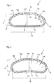
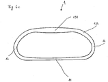
- Fig. 1 the cross section of a tube 1 is shown in one embodiment.
- the tube 1 has a cross section symmetrical to a plane of symmetry S.
- the inside width dimension B of the tube 1 is larger than the inside height dimension H.
- the tube 1 has a bottom wall 11, two side walls 12 and a top wall 13.
- the top wall 13 has a first area 131 and a second area 132.
- the first region 131 and the second region 132 are connected to one another and have different geometries.
- the geometries differ in that the first region 131 has a radius of curvature R1 which is comparatively large in relation to the internal height dimension H of the tube 1 and the second region 132 has a radius of curvature R2 which is comparatively small in relation to the internal dimension H of the tube 1.
- the second area 132 is adjoined by a third area 133, which is connected to the side wall 12 and has a radius of curvature R3 which corresponds approximately to the radius of curvature R1 of the first area 131. This creates a largely trapezoidal cross section of the ceiling wall 13. In in Fig.
- the first radius of curvature R1 and the third radius of curvature R3 are approximately 7 times the internal height dimension H of the tube 1.
- the radius of curvature R2 corresponds approximately to the internal height dimension H of the tube 1.
- Other radii of curvature or a straight design of the first region 131 and / or the third region 133 without radii of curvature R1, R3 are also encompassed by the invention.
- the largely trapezoidal design of the cross section of the top wall 13 supports the static stability of the tube 1.
- the side wall 12 has a radius of curvature R5, which leads to a good flow cross section.
- a straight side wall 12 without a radius of curvature R5 is also encompassed by the invention.
- the bottom wall 11 is straight in this embodiment, so that the tube can be placed on a floor or a ceiling.
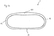
- Fig. 2 shows the cross section of the tube 1 Fig. 1 in a further embodiment.
- the bottom wall 11 likewise has a radius of curvature R4 which is relatively large in relation to the internal height dimension H of the tube 1 and here roughly corresponds to the radii R1, R3. Due to the slight curvature of the bottom wall 11 inwards, the pipe has only two support points or lines and is therefore more stable on a floor, since this embodiment is suitable for compensating for any unevenness in the screed. Due to the only slight curvature, the flow cross section of the tube 1 is not significantly reduced at the same time.
- Fig. 3 the cross section of the tube 1 is shown in a further embodiment.
- the tube 1 has wave crests 101 and wave troughs 102 on the outside.
- Inside the tube 1 there is an inner tube 103 with a flat, smooth inner surface, which is connected to the troughs 102.
- the tube 1 and the inner tube 103 preferably consist of a thermoplastic that is extrusion-capable, preferably of polyethylene or polypropylene.
- the tube 1 consists of a corrugated metal tube, preferably made of stainless steel, copper, aluminum or brass, into which an inner tube 103 made of a thermoplastic extrusion-resistant plastic or a metal foil, for example made of aluminum or stainless steel, is inserted, in particular glued or welded.
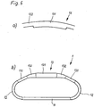
- Fig. 4 represents the cross section of the pipe 1 in a further embodiment.
- the pipe 1 lies on the screed 2.
- Thermal insulation 3 is arranged on both sides of the pipe 1. Cavities between the thermal insulation 3 and the pipe 1 are filled with a material 4. If the pipe 1 and the thermal insulation 3 are then covered with a further screed layer, the material 4 ensures that no voids form under the screed and the screed does not crack.
- Perlite fill or a heat-insulating material is used as material 4, for example. Due to the trapezoidal design of the top wall of the tube 1, the resulting cavity to be filled with the material 4 is kept relatively small. Furthermore, the cavity has a simple geometry, so that the material 4 to be inserted can be easily cut, for example by inserting a wedge shape. This facilitates the installation of the pipe 1 in the floor 5.
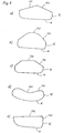
- FIG. 5 different pipe cross sections with different geometries are shown.
- the tube cross sections each have a bottom wall 11, side connections 12 and, as the top wall, a first area 131 and a second area 132.
- 5a, 5c, 5e and 5f are the first area 131 and the second area 132 formed as a straight line and inclined to each other so that they form a roof-shaped cross section.
- the roof-shaped cross section has in Fig. 5a roughly the shape of a gable roof, in Fig. 5c the shape of a hipped roof and in Fig. 5e and 5f the shape of a pent roof.
- the first area 131 is formed as a straight line and the second area 132 is curved.
- Fig. 5b the first area 131 is formed as a straight line and the second area 132 is curved.
- both the first region 131 and the second region 132 are curved.
- the second region 132 has a negative radius of curvature, ie it is curved inwards.
- Both the first region 131 and the second region 132 are curved inwards.
- Fig. 5h shows the pipe 5g as a stacked arrangement.
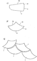
- Fig. 6 shows different pipe cross sections with different wall thicknesses.
- Fig. 6a a section of the ceiling wall 13 of a tube is shown.
- the height of the wall in the first area 131 is greater than in the second area 132
- Fig. 6b is the pipe according to Fig. 1 shown.
- the wall is thickened in the first region 131 and in the second region 132.
- Fig. 6c shows a cross section of the tube 1 in a further embodiment.
- the height of the wall is greater than in the second area 132 and in the area of the side connections 12.
- the height of the wall is less than in the second area 132 and in the area of the side walls 12.
- Fig. 6d shows a tube 1 with a first area 131, side connections 12 and a bottom wall 11.
- the height of the wall of the tube 1 is greater in the first area 131 than in the area of the side connections 12.
- the height of the wall is less than in the area of the side walls 12.
- Fig. 7 shows the cross section of the tube 11 in a further embodiment with a bottom wall 11, side connections 12 and a top wall 13.
- the curvature of the top wall 13 is continuous with curvature.
- the top wall has a multiplicity of regions 131, 132,... Each of which has different radii of curvature.
- Fig. 7b shows the cross section of the tube 1
- Fig. 7a the cross section of the tube 1 in an enlarged view with a representation of the curvature K, the radii given are only exemplary, so that between the individual radii there is an undetermined number of further radii.
- the side connection 12 also has a multiplicity of regions with different radii of curvature, so that there is a curvature-constant course from the bottom wall 11 to the top wall 13 and within the top wall 13.
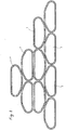
- Fig. 8 are different pipes 1 from Fig. 1 shown. This shows the good stackability of pipes 1 according to FIG Fig. 1 recognizable due to the cross-section.
- Fig. 9 shows a section of the tube 1 with wave crests 101, between which a wave trough 102 is arranged. Furthermore, the tube 1 has an inner tube 103.
- the wall thickness of the wave crests 101 and wave troughs 102 preferably varies between approximately 0.2 and 1.0 mm, in particular approximately 0.5 mm to 0.9 mm, preferably approximately 0.6 and 0.85 mm, the thinnest point in the area of the wave crest 101 and the thickest point in the area of the wave trough 102 is formed.
- Fig. 9a shows an enlarged view of two wave crests 101 and Fig. 9b an enlarged view of a wave crest 102.
Landscapes
- Engineering & Computer Science (AREA)
- General Engineering & Computer Science (AREA)
- Mechanical Engineering (AREA)
- Physics & Mathematics (AREA)
- Thermal Sciences (AREA)
- Chemical & Material Sciences (AREA)
- Combustion & Propulsion (AREA)
- Rigid Pipes And Flexible Pipes (AREA)
Description
- Die Erfindung betrifft ein Rohr zur Leitung eines Fluids, bestehend aus einer Bodenwandung, Seitenanbindungen und einer Deckenwandung.
- Derartige Rohre finden in verschiedenen Bereichen Verwendung, beispielsweise als Abwasserrohr oder als Luftführungsrohr in Klima- und Lüftungsanlagen. Im Bereich der Klima- und Lüftungstechnik wird ein solches Rohr vorzugsweise horizontal innerhalb eines Estrichs eines Gebäudes verlegt.
- Da bei der Verlegung des Rohrs innerhalb eines Estrichs nur eine geringe Bauhöhe zur Verfügung steht, werden im Stand der Technik Rohre mit einem länglichen Querschnitt verwendet. So zeigt die
DE 27 52 622 A1 ein Wellrohr mit einem elliptischen Querschnitt. Daneben werden auch Rohre mit einem ovalen Querschnitt verwendet. - Die
EP 2 019 242 A2 zeigt ein Rohr, das einen Querschnitt mit einer sich über die gesamte Breite des Rohres erstreckenden geradlinig verlaufenden Seite aufweist, deren beide Enden durch eine gewölbeartig gekrümmt verlaufende Seite miteinander verbunden sind. Als weiterer Stand der Technik wird hingewiesen aufDE 10 2008 013 013 A1 ,WO 2004/001293 A1 ,US 2007/0267012 A1 ,DE 29 18 058 A1 ,DE 177565 ,GB 27 782 US 6 024 130 . DieDE 2918058 A1 offenbart ein Rohr für eine Ent- oder Belüftungsleitung mit verschiedenen in Frage kommenden Querschnitten, wobei man statt eckigen Ausführungsformen wiederum an den Ecken mehr oder minder gerundete Ausführungsformen wählen kann. - Aus
EP 2 131 114 B1 ist ein Rohr bekannt. Das Dokument offenbart ein Kunststoffrohr zum Weiterleiten eines Fluids für Klima- oder Lüftungsanlagen hervor, das aus einem flexiblen Wellrohr mit einem zu einer Symmetrieebene symmetrisch ausgebildeten Querschnitt besteht. Der Querschnitt wird von einer ebenen Bodenwandung und einer gegenüberliegenden bogenförmig nach außen gewölbten Deckenwandung und dazwischen angeordneten Seitenwandungen begrenzt, wobei der Radius der Krümmung der Deckenwandung mindestens dem 1,5-fachen, aber maximal dem Fünffachen der Höheninnenabmessung entspricht. Die Bodenwandung, die Seitenwandungen und die Deckenwandungen gehen dabei bogenförmig ineinander über. - Als weiteren Stand der Technik wird auch hingewiesen auf
US 2010/0200100 A1 sowieDE 41 22 388 A1 . - Das Dokument
US 2010/0200100 A1 zeigt zwar ein Rohr, dessen Bodenwandung nach innen gekrümmt ist, allerdings ist die dort gezeigte Deckenwandung des Rohrs im Querschnitt weder trapezförmig ausgebildet, noch offenbart das Dokument, dass der Krümmungsradius der Bodenwand in irgendeiner Weise im Verhältnis steht zum Krümmungsradius des ersten Bereichs der Deckenwandung. Den gleichen Offenbarungsinhalt hierzu zeigt auch das DokumentDE 41 22 388 A1 . - Aus
EP 2 131 114 B1 ist ein Rohr für die Haustechnik zur Leitung eines Fluids bekannt, bei welchem das Rohr aus einer Bodenwandung, Seitenanbindung und einer Deckwandung besteht und wobei die Deckenwandung im Querschnitt trapezförmig ausgebildet ist. Ferner offenbart das Dokument ein Kunststoffrohr zum Weiterleiten eines Fluids für Klima- und Lüftungsanlagen, wobei das Rohr aus einem flexiblen Wellrohr mit einem zu einer Symmetrieebene symmetrisch ausgebildeten Querschnitt besteht. Der Querschnitt wird von einer ebenen Bodenwandung und einer gegenüberliegenden bogenförmig nach außen gewölbten Deckenwandung und dazwischen angeordneten Seitenwandungen begrenzt, wobei der Radius der Krümmung der Deckenwandung mindestens dem 1,5-fachen, aber maximal dem 5-fachen der Höhenabmessung entspricht. Die Bodenwandung, die Seitenwandung und die Deckenwandung gehen dabei bogenförmig ineinander über. - Ausgehend vom Stand der Technik liegt der Erfindung die Aufgabe zugrunde, ein Rohr zur Leitung eines Fluids vorzusehen, das einerseits einen großen Strömungsquerschnitt aufweist, andererseits aber statisch stabil und bei Verlegung innerhalb eines Estrichs gegen Trittbelastungen widerstandsfähig ist. Weiterhin soll ein Rohr vorgesehen werden, das kompakt und stapelbar ist und einfach innerhalb eines Estrichs verlegbar ist.
- Außerdem liegt der Erfindung die Aufgabe zugrunde, ein Rohr vorzusehen, das leicht biegbar ist.
- Erfindungsgemäß ist die obige Aufgabe durch die Merkmale des Anspruchs 1 gelöst. Vorteilhafte Ausführungen der Erfindung sind in den Unteransprüchen gegeben.
- Danach weist die Deckenwandung wenigstens einen ersten Bereich und einen zweiten Bereich auf, wobei die Bereiche miteinander verbunden sind und unterschiedliche Geometrien aufweisen.
- Vorzugsweise ist ein solches Rohr in Haustechnikgeräten oder -anlagen, beispielsweise zur Wasserleitung oder als Heizungsrohr für eine Fußboden- oder Wandheizung eingesetzt. In einem weiteren Ausführungsbeispiel ist das Rohr innerhalb eines Haustechnikgerätes zur Leitung eines Fluids verwendet, z.B. zur Verbindung von Komponenten des Gerätes oder zum Anschluss an ein Fluidnetz. In einer bevorzugten Ausführungsform ist das Rohr in einem Durchlauferhitzer oder einem Warmwasserspeicher verwendet, die über ein flexibles Rohr an ein Wassernetz angeschlossen sind. In einer weiteren Ausgestaltung der Erfindung ist das Rohr in einer Wärmepumpe vorzugsweise zur Fluidleitung, insbesondere von Kältemittel, Wasser oder einem anderen Wärmeträgermedium verwendet, z.B. für den Anschluss an ein Heizungs- oder Brauchwassersystem. In einer weiteren bevorzugten Ausführungsform der Erfindung ist das Rohr innerhalb einer Solaranlage, insbesondere für die Anschlüsse und Verbindung von Kollektoren oder die Leitung eines Wärmeträgermediums verwendet. Vorzugsweise ist das Rohr für die Luftführung in einer Klima- oder Lüftungsanlage verwendet. Bei der Verwendung des Rohres bei einer Klima- oder Lüftungsanlage wird das Rohr vorzugsweise innerhalb eines Estrichs verlegt.
- In einer bevorzugten Ausgestaltung der Erfindung beträgt die Breite des Rohres ca. 100 bis 150 mm, insbesondere ca. 130 bis 140 mm, insbesondere 132,8 mm.
- Die Höhe des Rohres beträgt vorzugsweise ca. 40 bis 60 mm, insbesondere ca. 50 bis 55 mm, insbesondere 52 mm.
- In einer besonders vorteilhaften Ausgestaltung der Erfindung beträgt die Breite des Rohres 132,8 mm und die Höhe 52 mm.
- Vorzugsweise besteht das Rohr aus einem Wellrohr mit Wellenbergen und Wellentälern. Im Inneren des Rohres ist vorzugsweise ein Innenschlauch mit einer ebenen, glatten Innenfläche angeordnet, der mit den Wellentälern verbunden ist.
- Die Wellenberge weisen dabei vorzugsweise eine Breite von ca. 2 bis 6 mm, insbesondere ca. 3 bis 4 mm, insbesondere ca. 3,4 mm auf.
- In einer bevorzugten Ausführungsform sind die Wellenberge in einem Abstand von ca. 4 bis 8 mm, insbesondere ca. 5 bis 6 mm, insbesondere ca. 5,7 mm, gemessen am Scheitelpunkt, voneinander angeordnet.
- Die Höhe der Wellenberge beträgt bevorzugt ca. 3 bis 6 mm, insbesondere ca. 4 bis 5 mm, vorzugsweise ca. 4,5 mm.
- In einer bevorzugten Ausgestaltung der Erfindung beträgt der Abstand der Wellenberge ca. 5,7 mm, die Breite der Wellenberge ca. 3,4 mm und die Höhe der Wellenberge ca. 4,5 mm.
- Vorzugsweise besteht das Rohr sowie der Innenschlauch aus einem thermoplastischen Kunststoff, der extrusionsfähig ist, vorzugsweise aus Polyethylen oder Polypropylen.
- In einer bevorzugten Ausführungsform besteht das Außenrohr aus Polyethylen mit einer hohen Dichte mit der technischen Bezeichnung PE-HD und das Innenrohr aus Polyethylen mit einer niedrigen Dichte mit der technischen Bezeichnung PE-LD.
- In einem weiteren bevorzugten Ausführungsbeispiel besteht das Außenrohr aus PE-HD und das Innenrohr aus Ethylenvinylacetat mit der technischen Bezeichnung EVA.
- In einer weiteren vorteilhaften Ausführungsform besteht das Außenrohr aus Polyethylen, welches eine mittlere Dichte aufweist, mit der technischen Bezeichnung PE-MD und das Innenrohr aus PE-LD.
- Nach einem weiteren Ausführungsbeispiel besteht das Außenrohr aus PE-HD und das Innenrohr aus PE-MD.
- In einer weiteren Ausgestaltung der Erfindung besteht das Außenrohr aus PE-MD und das Innenrohr aus EVA.
- In einem weiteren Ausführungsbeispiel bestehen sowohl das Außenrohr als auch das Innenrohr aus PE-HD oder aus PE-MD.
- Gemäß einer weiteren Ausgestaltung besteht das Außenrohr aus PE-LD und das Innenrohr aus PE-LD oder EVA.
- In einem weiteren Ausführungsbeispiel besteht das Außenrohr aus Polyproplylen mit der technischen Bezeichnung PP und das Innenrohr aus PE-LD, PP oder EVA.
- Vorzugsweise weist das PE-HD eine Dichte von ca. 940-970 kg/m3, das PE-MD von ca. 930-940 kg/m3, das PE-LD von ca. 915-930 kg/m3, das PP von ca. 900-915 kg/m3 und das EVA von ca. 940 kg/m3 auf.
- Durch die Kombination dieser Materialien ist eine gute Biegbarkeit bei gleichzeitiger Trittfestigkeit erreicht.
- Vorzugsweise weist das PE-HD einen Schmelzpunkt von 135°C, das PE-MD von 125°C, das PE-LD von 110°C, das PP von 160°C und das EVA von 105°C auf.
- Bei der Kombination unterschiedlicher Materialien unterscheiden sich die Schmelzpunkte der Materialien vorzugsweise um maximal ca. 50 °C, vorzugsweise um 0°C bis ca. 30°C. Hierdurch ist erreicht, dass sich Außenrohr und Innenrohr gut miteinander verbinden und sich das Innenrohr zu einem späteren Zeitpunkt nicht wieder ablöst.
- In einem weiteren Ausführungsbeispiel besteht das Rohr aus einem Metallwellrohr, vorzugsweise aus Edelstahl, Kupfer, Aluminium oder Messing, in das ein Innenrohr aus einem thermoplastischen extrusionsfähigen Kunststoff oder einer Metallfolie, beispielsweise aus Aluminium oder Edelstahl, eingelegt, insbesondere eingeklebt oder eingeschweißt ist.
- In einem Ausführungsbeispiel ist die Deckenwandung bogenförmig gekrümmt, wobei die Geometrien insofern unterschiedlich sind, als der erste Bereich und der zweite Bereich unterschiedliche Krümmungsradien aufweisen. Hierdurch erhält das Rohr einen großen Strömungsquerschnitt, bleibt aber gegen Trittbelastungen widerstandsfähig. Vorzugsweise ist der Krümmungsradius des ersten Bereichs möglichst groß und der Krümmungsradius des zweiten Bereichs möglichst klein gewählt. Hierdurch wird die bei Trittbelastung auf das Rohr wirkende Kraft in Richtung der Seitenanbindungen abgeleitet, wodurch das Rohr nicht einknickt.
- Erfindungsgemäß entspricht der erste Krümmungsradius des ersten Bereichs mindestens dem 5,5-fach der Höheninnenabmessung des Rohres und der zweite Krümmungsradius des zweiten Bereichs höchstens dem 1,4-fachen der Höheninnenabmessung. Hierdurch erhält der Querschnitt der Deckenwandung eine weitgehend trapezförmige Form. In einem weiteren aber nicht zur Erfindung gehörigen Ausführungsbeispiel geht der erste Krümmungsradius gegen Unendlich, so dass der erste Bereich nahezu eben ausgeführt ist. Eine weitere aber nicht zur Erfindung gehörige Ausführungsform stellt ein negativer Krümmungsradius, also eine Krümmung nach innen dar, wodurch die Stapelbarkeit des Rohres verbessert ist.
- Erfindungsgemäß schließt sich dem zweiten Bereich der Deckenwandung ein dritter Bereich an, der einen dritten Krümmungsradius aufweist. Beim Verlegen des Rohres innerhalb eines Estrichs ist diese Form besonders vorteilhaft, da zwischen dem Rohr und einer beidseitig neben dem Rohr anzuordnenden Wärmedämmung ein Hohlraum entsteht und dieser Hohlraum durch den vorgeschlagenen Querschnitt sehr klein gehalten ist.
- In einem weiteren aber nicht zur Erfindung gehörigen Ausführungsbeispiel weisen der erste Bereich und der zweite Bereich insofern unterschiedliche Geometrien auf, als erste Bereich und der zweite Bereich aus Geraden unterschiedlicher Neigung gebildet sind. Die Deckenwand erhält dadurch einen dachförmigen Querschnitt. Vorteilhafte Ausgestaltungen der Erfindung sind beispielsweise eine Satteldachform, eine Pultdachform oder eine Walmdachform.
- In einer weiteren aber nicht zur Erfindung gehörigen Ausgestaltung der Erfindung sind die unterschiedlichen Geometrien durch unterschiedliche Formen gebildet. Beispielsweise ist der erste Bereich gekrümmt und der zweite Bereich eben oder umgekehrt.
- In einer weiteren aber nicht zur Erfindung gehörigen sind der erste Bereich und der zweite Bereich durch unterschiedliche Parabeln gebildet.
- Vorzugsweise weist die Deckenwandung im ersten Bereich und im zweiten Bereich unterschiedliche Wandstärken auf. Bevorzugt ist dem ersten Bereich die Höhe der Wandung größer ausgebildet, wodurch das Rohr eine zusätzliche Stabilität erhält. Vorzugsweise ist die Höhe der Wandung im ersten Bereich um den Faktor 1,1 bis 5,0 größer als im zweiten Bereich, insbesondere um den Faktor 1,5 bis 3,0. In einer weiteren Ausgestaltung der Erfindung ist die Höhe der Wandung in einem dritten Bereich, im Bereich der Seitenanbindungen und/oder im Bereich der Bodenwandung kleiner als im zweiten Bereich. Vorzugsweise ist die Höhe dort um den Faktor 1,1 bis 5,0, insbesondere um den Faktor 1,5 bis 3,0 kleiner als in der zweiten Zone. Dies hat den Vorteil, dass das Rohr durch die Verdickung im ersten Bereich zwar stabil ausgeführt ist, gleichzeitig jedoch der Strömungsquerschnitt nicht nennenswert verringert ist.
- Vorzugsweise ist das Außenrohr im Bereich der Wellentäler und Wellenberge unterschiedlich dick ausgebildet, um die Flexibilität des Rohres zu erhöhen, gleichzeitig aber die Trittfestigkeit beizubehalten.
- Die Wandstärke variiert dabei vorzugsweise zwischen ca. 0,2 und 1,0 mm, insbesondere ca. 0,5 mm bis 0,9 mm, vorzugsweise ca. 0,6 und 0,85 mm, wobei die dünnste Stelle im Bereich des Wellenberges und die dickste Stelle im Bereich des Wellentales ausgebildet ist.
- Die Wandstärke des Innenrohres beträgt vorzugsweise ca. 0,1 bis 0,5 mm, insbesondere ca. 0,1 bis 0,2 mm, um die Flexibilität des Rohres zu erhöhen.
- Erfindungsgemäß weist die Bodenwandung einen vierten Krümmungsradius auf. Erfindungsgemäß ist die Bodenwandung leicht nach innen gekrümmt. Durch diese leichte Krümmung liegt das Rohr beim Verlegen innerhalb eines Estrichs nicht vollflächig auf, sondern es hat lediglich zwei Auflagepunkte bzw. -linien. Dadurch liegt es sehr stabil auf dem Estrich auf, da es durch diese Ausführungsform geeignet ist, etwaige Unebenheiten im Estrich auszugleichen. Durch die nur leichte Krümmung ist dabei der Strömungsquerschnitt des Rohres 1 gleichzeitig nicht nennenswert verringert. Bevorzugt ist das Rohr flexibel, so dass es flexibel verlegbar ist und zusätzlich Unebenheiten im Estrich ausgleicht.
- In einer weiteren bevorzugten Ausgestaltung der Erfindung weist die Deckenwandung eine Vielzahl von Bereichen mit unterschiedlichen Krümmungsradien auf. Die Krümmungsradien ändern sich konstant und führen so zu einer krümmungsstetigen Krümmung der Deckenwandung. Vorzugsweise weist auch die Seitenwandung eine Vielzahl von Bereichen mit unterschiedlichen Krümmungsradien auf, so dass von der Bodenwandung bis zur Deckenwandung und innerhalb der Deckenwandung ein krümmungsstetiger Verlauf gegeben ist.
- Erfindungsgemäß ist die Deckenwandung mit der Bodenwandung über Seitenanbindungen verbunden. In einem Ausführungsbeispiel sind die Seitenanbindungen durch einen weiteren Radius gebildet, um einen großen Strömungsquerschnitt zu erzeugen. In einer weiteren bevorzugten Ausgestaltung der Erfindung sind die Seitenanbindungen durch eine Wandung gebildet, die weitgehend gerade ausgebildet ist, wodurch eine gute Stapelbarkeit des Rohres erreicht ist.
- Vorzugsweise weist das Rohr einen Außenumfang von ca. 200 mm ns 400 mm, insbesondere ca. 300 bis 350 mm, vorzugsweise 315 mm, und eine Querschnittsfläche bezogen auf den Außenumfang von ca. 5000 bis 7000 mm, insbesondere ca. 5500 bis 6000 mm2, vorzugsweise 5750 mm2, auf.
- In einer weiteren bevorzugten Ausgestaltung der Erfindung weist das Rohr einen Innenumfang von ca. 200 bis 400 mm, insbesondere ca. 250 bis 300 mm, vorzugsweise 278 mm, und eine Querschnittsfläche bezogen auf den Innenumfang von ca. 3000 bis 5000 mm, insbesondere ca. 3800 bis 4200 mm2, vorzugsweise 4011 mm2, auf. Die Querschnittsfläche bezogen auf den Innendurchmesser entspricht dabei der durchströmbaren Fläche.
- Das spezifische Gewicht des Innenrohrs beträgt vorzugsweise ca. 20 - 100 g/m, das des Außenrohrs vorzugsweise ca. 400 - 600 g/m.
- Vorzugsweise wird das Rohr im Wege des Extrusionsverfahrens hergestellt. Dabei wird Kunststoff geschmolzen und sodann unter Druck durch eine speziell geformte Düse gepresst, wodurch es eine spezifische Form erhält. Anschließend kühlt das Rohr ab und behält dabei seine Form.
- In einer bevorzugten Ausgestaltung der Erfindung wird das abkühlende Rohr mit Wasser besprüht. Der abkühlende Kunststoff kristallisiert nach der Herstellung noch ca. 24 Stunden nach. Eine Deformation während dieser Zeit ist irreversibel, da der Kunststoff immer wieder die Form annimmt, die er während der Abkühl- und Nachkristallisationsphase hatte. Durch das schnelle Abkühlen des Rohres durch Besprühen mit Wassersprühnebel wird der zu dem Zeitpunkt existierende geometrische Zustand erhalten und die weitere Schwindung durch die Nachkristallisation ist weniger schädlich. Durch diese Maßnahme ist die Trittfestigkeit des Rohres verbessert.
- In der Zeichnung zeigen
- Figur 1
- einen Rohrquerschnitt in einem Ausführungsbeispiel (nicht zur Erfindung gehörig)
- Figur 2
- einen Rohrquerschnitt gemäß einem erfindungsgemäßen Ausführungsbeispiel
- Figur 3
- einen Rohrquerschnitt in einem weiteren Ausführungsbeispiel
- Figur 4
- einen Rohrquerschnitt in einem weiteren erfindungsgemäßen Ausführungsbeispiel
- Figur 5
- verschiedene Rohrquerschnitte mit unterschiedlichen Geometrien (nicht zur Erfindung gehörig)
- Figur 6
- einen Rohrquerschnitt mit unterschiedlichen Wanddicken
- Figur 7
- einen Rohrquerschnitt in einem weiteren Ausführungsbeispiel (nicht zur Erfindung gehörig)
- Figur 8
- eine Anordnung von Rohren in einem Ausführungsbeispiel (nicht zur Erfindung gehörig)
- Figur 9
- einen Ausschnitt des Rohres in einem Ausführungsbeispiel
- In der Beschreibung und den Figuren, z.B. in
Fig. 6b ,6c ,6d und6e , sind auch Ausführungsformen angegeben, die nicht in den Ansprüchen erfasst sind. Hierbei handelt es sich nicht um Ausführungsformen der Erfindung, sondern um Aspekte, die das Verständnis der Erfindung erleichtern. - In
Fig. 1 ist der Querschnitt eines Rohres 1 in einem Ausführungsbeispiel gezeigt. Das Rohr 1 weist einen zu einer Symmetrieebene S symmetrisch ausgebildeten Querschnitt auf. Die Breiteninnenabmessung B des Rohres 1 ist dabei größer als die Höheninnenabmessung H. Das Rohr 1 weist eine Bodenwandung 11, zwei Seitenwandungen 12 und eine Deckenwandung 13 auf. Die Deckenwandung 13 weist einen ersten Bereich 131 und einen zweiten Bereich 132 auf. Der erste Bereich 131 und der zweite Bereich 132 sind miteinander verbunden und weisen unterschiedliche Geometrien auf. In diesem Ausführungsbeispiel sind die Geometrien insofern unterschiedlich, als der erste Bereich 131 einen im Verhältnis zur Höheninnenabmessung H des Rohres 1 vergleichsweise großen Krümmungsradius R1 und der zweite Bereich 132 einen im Verhältnis zur Höheninnenabmessung H des Rohres 1 vergleichsweise kleinen Krümmungsradius R2 aufweist. An den zweiten Bereich 132 schließt sich ein dritter Bereich 133 an, der mit der Seitenwandung 12 verbunden ist und einen Krümmungsradius R3 aufweist, der in etwa dem Krümmungsradius R1 des ersten Bereiches 131 entspricht. Hierdurch entsteht ein weitgehend trapezförmiger Querschnitt der Deckenwandung 13. In inFig. 1 gezeigtem Ausführungsbeispiel betragen der erste Krümmungsradius R1 und der dritte Krümmungsradius R3 in etwa das 7-fache der Höheninnenabmessung H des Rohres 1. Der Krümmungsradius R2 entspricht in etwa der Höheninnenabmessung H des Rohres 1. Diese Maße sind jedoch lediglich beispielhaft zu sehen. So sind andere Krümmungsradien oder eine gerade Ausführung des ersten Bereichs 131 und/oder des dritten Bereich 133 ohne Krümmungsradien R1, R3 ebenfalls von der Erfindung umfasst. Die weitgehend trapezförmige Ausführung des Querschnitts der Deckenwandung 13 unterstützt die statische Stabilität des Rohres 1. Die Seitenwandung 12 weist einen Krümmungsradius R5 auf, was zu einem guten Strömungsquerschnitt führt. Jedoch ist auch eine gerade Seitenwand 12 ohne Krümmungsradius R5 von der Erfindung umfasst. Die Bodenwand 11 ist in diesem Ausführungsbeispiel gerade ausgeführt, so dass das Rohr eben auf einen Fußboden oder eine Decke auflegbar ist. -
Fig. 2 zeigt den Querschnitt des Rohres 1 ausFig. 1 in einem weiteren Ausführungsbeispiel. Jedoch weist in diesem Ausführungsbeispiel die Bodenwand 11 ebenfalls einen Krümmungsradius R4 auf, der im Verhältnis zur Höheninnenabmessung H des Rohres 1 relativ groß gewählt ist und hier in etwa den Radien R1, R3 entspricht. Durch die leichte Krümmung der Bodenwandung 11 nach innen hat das Rohr lediglich zwei Auflagepunkte bzw. -linien und liegt somit stabiler auf einem Fußboden auf, da es durch diese Ausführungsform geeignet ist, etwaige Unebenheiten im Estrich auszugleichen. Durch die nur leichte Krümmung ist dabei der Strömungsquerschnitt des Rohres 1 gleichzeitig nicht nennenswert verringert. - In
Fig. 3 ist der Querschnitt des Rohres 1 in einem weiteren Ausführungsbeispiel gezeigt. Das Rohr 1 weist außen Wellenberge 101 und Wellentäler 102 auf. Im Inneren des Rohres 1 ist ein Innenschlauch 103 mit einer ebenen, glatten Innenfläche angeordnet, der mit den Wellentälern 102 verbunden ist. Vorzugsweise besteht das Rohr 1 sowie der Innenschlauch 103 aus einem thermoplastischen Kunststoff, der extrusionsfähig ist, vorzugsweise aus Polyethylen oder Polypropylen. In einem weiteren Ausführungsbeispiel besteht das Rohr 1 aus einem Metallwellrohr, vorzugsweise aus Edelstahl, Kupfer, Aluminium oder Messing, in das ein Innenrohr 103 aus einem thermoplastischen extrusionsfähigen Kunststoff oder einer Metallfolie, beispielsweise aus Aluminium oder Edelstahl, eingelegt, insbesondere eingeklebt oder eingeschweißt ist. -
Fig. 4 stellt den Querschnitt des Rohres 1 in einem weiteren Ausführungsbeispiel dar. Hier ist in einem Ausschnitt der Einbau des Rohres 1 in einen Fußboden 5 gezeigt. Das Rohr 1 liegt auf dem Estrich 2 auf. Beidseitig des Rohres 1 ist eine Wärmedämmung 3 angeordnet. Hohlräume zwischen der Wärmedämmung 3 und dem Rohr 1 werden mit einem Material 4 aufgefüllt. Wird das Rohr 1 und die Wärmedämmung 3 sodann mit einer weiteren Estrichschicht überzogen, sorgt das Material 4 dafür, dass sich unter dem Estrich keine Hohlräume bilden und der Estrich nicht reißt. Als Material 4 wird beispielsweise eine Perlite-Schüttung oder ein wärmedämmendes Material verwendet. Durch die trapezförmige Ausgestaltung der Deckenwandung des Rohres 1 ist der entstehende, mit dem Material 4 zu füllende Hohlraum relativ klein gehalten. Weiterhin weist der Hohlraum eine einfache Geometrie auf, so dass das einzulegende Material 4 einfach zuschneidbar ist, indem beispielsweise eine Keilform eingelegt wird. Dies erleichtert den Einbau des Rohres 1 in den Fußboden 5. - In
Fig. 5 sind verschiedene Rohrquerschnitte mit unterschiedlichen Geometrien gezeigt. Die Rohrquerschnitte weisen jeweils eine Bodenwandung 11, Seitenanbindungen 12 und als Deckenwandung einen ersten Bereich 131 und einen zweiten Bereich 132 auf. InFig. 5a, 5c, 5e und5f sind der erste Bereich 131 und der zweite Bereich 132 als Geraden ausgebildet und so zueinander geneigt, dass sie einen dachförmigen Querschnitt bilden. Der dachförmige Querschnitt hat inFig. 5a in etwa die Form eines Satteldaches, inFig. 5c die Form eines Walmdaches und inFig. 5e und5f die Form eines Pultdaches. InFig. 5b ist der erste Bereich 131 als Gerade ausgebildet und der zweite Bereich 132 ist gekrümmt. InFig. 5d ist sowohl der erste Bereich 131 als auch der zweite Bereich 132 gekrümmt. Der zweiten Bereich 132 weist dabei einen negativen Krümmungsradius auf, ist also nach innen gekrümmt. InFig. 5g ist sowohl der erste Bereich 131 als auch der zweite Bereich 132 nach innen gekrümmt.Fig. 5h zeigt das Rohr ausFig. 5g als gestapelte Anordnung. -
Fig. 6 zeigt verschiedene Rohrquerschnitte mit unterschiedlichen Wanddicken. InFig. 6a ist ein Ausschnitt der Deckenwandung 13 eines Rohres gezeigt. Die Höhe der Wandung im ersten Bereich 131 ist dabei größer als im zweiten Bereich 132. InFig. 6b ist das Rohr gemäßFig. 1 gezeigt. Im ersten Bereich 131 und im zweiten Bereich 132 ist hierbei die Wandung verdickt.Fig. 6c zeigt einen Querschnitt des Rohres 1 in einer weiteren Ausführungsform. Im ersten Bereich 131 ist die Höhe der Wandung größer als im zweiten Bereich 132 und im Bereich der Seitenanbindungen 12. Im Bereich der Bodenwandung 11 ist dagegen die Höhe der Wandung kleiner als im zweiten Bereich 132 und im Bereich der Seitenwandungen 12. InFig. 6d ist sowohl im ersten Bereich 131 als auch im Bereich der Bodenwandung 11 die Wandung ausgedünnt. Im zweiten Bereich 132 und im Bereich der Seitenwandungen ist sie dagegen verdickt.Fig. 6e zeigt ein Rohr 1 mit einem ersten Bereich 131, Seitenanbindungen 12 und einer Bodenwandung 11. Die Höhe der Wandung des Rohres 1 ist im ersten Bereich 131 größer als im Bereich der Seitenanbindungen 12. Im Bereich der Bodenwandung 11 ist die Höhe der Wandung dagegen kleiner als im Bereich der Seitenwandungen 12. -
Fig. 7 zeigt den Querschnitt des Rohres 11 in einem weiteren Ausführungsbeispiel mit einer Bodenwandung 11, Seitenanbindungen 12 und einer Deckenwandung 13. Die Krümmung der Deckenwandung 13 verläuft dabei krümmungsstetig. Die Deckenwandung weist eine Vielzahl von Bereichen 131, 132, ... auf, die jeweils unterschiedliche Krümmungsradien aufweisen.Fig. 7b zeigt dabei den Querschnitt des Rohres 1,Fig. 7a den Querschnitt des Rohres 1 in einer vergrößerten Ansicht mit einer Darstellung der Krümmung K, wobei die angegebenen Radien lediglich beispielhaft sind, so dass zwischen den einzelnen Radien eine unbestimmte Anzahl weiterer Radien liegt. Auch die Seitenanbindung 12 weist eine Vielzahl von Bereichen mit unterschiedlichen Krümmungsradien auf, so dass von der Bodenwandung 11 bis zur Deckenwandung 13 und innerhalb der Deckenwandung 13 ein krümmungsstetiger Verlauf gegeben ist. - In
Fig. 8 sind verschiedene Rohre 1 ausFig. 1 gezeigt. Hieraus ist die gute Stapelbarkeit von Rohren 1 gemäßFig. 1 aufgrund des Querschnitts erkennbar. -
Fig. 9 zeigt einen Ausschnitt des Rohres 1 mit Wellenbergen 101, zwischen denen ein Wellental 102 angeordnet ist. Weiterhin weist das Rohr 1 ein Innenrohr 103 auf. Die Wandstärke der Wellenberge 101 und Wellentäler 102 variiert dabei vorzugsweise zwischen ca. 0,2 und 1,0 mm, insbesondere ca. 0,5 mm bis 0,9 mm, vorzugsweise ca. 0,6 und 0,85 mm, wobei die dünnste Stelle im Bereich des Wellenberges 101 und die dickste Stelle im Bereich des Wellentales 102 ausgebildet ist.Fig. 9a zeigt dabei eine vergrößerte Ansicht zweier Wellenberge 101 undFig. 9b einen vergrößerte Ansicht eines Wellenbergs 102.
Claims (3)
- Rohr (1) für die Haustechnik zur Leitung eines Fluids, bestehend aus einer Bodenwandung (11), Seitenanbindungen (12) und einer Deckenwandung (13), wobei die Deckenwandung (13) im Querschnitt trapezförmig ausgestaltet ist und wenigstens einen ersten Bereich (131) und einen zweiten Bereich (132) aufweist, wobei die beiden Bereiche (131, 132) miteinander verbunden sind und unterschiedliche Geometrien aufweisen, wobei der erste Bereich (131) der Deckenwandung (13) einen ersten Krümmungsradius (R1) und der zweite Bereich (132) der Deckenwandung (13) einen zweiten Krümmungsradius (R2) aufweist, wobei der erste Krümmungsradius des ersten Bereichs (131) mindestens dem 5,5-fachen, insbesondere dem 7-fachen, der Höheninnenabmessung (H) des Rohres (1) entspricht und der zweite Krümmungsradius (R2) höchstens dem 1,4-fachen, insbesondere dem 1-fachen, der Höheninnenabmessung (H) entspricht, wobei sich dem zweiten Bereich (132) der Deckenwandung (13) ein dritter Bereich (133) anschließt, der mit den Seitenanbindungen (12) verbunden ist, wobei der dritte Bereich (133) einen dritten Krümmungsradius (R3) aufweist, wobei der dritte Krümmungsradius (R3) in etwa dem Krümmungsradius (R1) des ersten Bereiches (131) entspricht, wobei die Bodenwandung (11) nach innen leicht gekrümmt ist und einen vierten Krümmungsradius (R4) aufweist, der in etwa dem ersten und dritten Krümmungsradius (R1, R3) der Deckenwandung (13) entspricht.
- Rohr (1) gemäß Anspruch 1, dadurch gekennzeichnet, dass die Bereiche (131, 132) unterschiedliche Wandstärken aufweisen.
- Rohr (1) gemäß einem oder mehreren der vorhergehenden Ansprüche 1 oder 2, dadurch gekennzeichnet, dass die Deckenwandung (13) aus einer Vielzahl von Bereichen (131, 132) mit unterschiedlichen Krümmungsradien besteht.
Priority Applications (1)
| Application Number | Priority Date | Filing Date | Title |
|---|---|---|---|
| PL11007561T PL2431642T3 (pl) | 2010-09-16 | 2011-09-16 | Rura do przewodzenia płynu |
Applications Claiming Priority (1)
| Application Number | Priority Date | Filing Date | Title |
|---|---|---|---|
| DE202010012660U DE202010012660U1 (de) | 2010-09-16 | 2010-09-16 | Rohr zur Leitung eines Fluids |
Publications (3)
| Publication Number | Publication Date |
|---|---|
| EP2431642A2 EP2431642A2 (de) | 2012-03-21 |
| EP2431642A3 EP2431642A3 (de) | 2016-10-19 |
| EP2431642B1 true EP2431642B1 (de) | 2020-02-26 |
Family
ID=43299554
Family Applications (1)
| Application Number | Title | Priority Date | Filing Date |
|---|---|---|---|
| EP11007561.1A Active EP2431642B1 (de) | 2010-09-16 | 2011-09-16 | Rohr zur Leitung eines Fluids |
Country Status (5)
| Country | Link |
|---|---|
| EP (1) | EP2431642B1 (de) |
| DE (1) | DE202010012660U1 (de) |
| ES (1) | ES2791763T3 (de) |
| LT (1) | LT2431642T (de) |
| PL (1) | PL2431642T3 (de) |
Cited By (1)
| Publication number | Priority date | Publication date | Assignee | Title |
|---|---|---|---|---|
| EP4105587B1 (de) | 2021-06-16 | 2024-09-18 | Zehnder Group International AG | Rohr zum transport eines wärmetragenden fluides |
Families Citing this family (9)
| Publication number | Priority date | Publication date | Assignee | Title |
|---|---|---|---|---|
| DE102011118939A1 (de) * | 2011-11-21 | 2013-05-23 | Westfalia Metallschlauchtechnik Gmbh & Co. Kg | Ausführungsform streckbarer Metallschläuche und zugehöriges Werkzeugelement |
| DE102017105265A1 (de) | 2017-03-13 | 2018-09-13 | Stiebel Eltron Gmbh & Co. Kg | Wärmeübertragerrohr und Wärmeübertrager-Baugruppe |
| DE102017105787B3 (de) * | 2017-03-17 | 2018-06-28 | Schlemmer Holding GmbH | Verbundschlauch |
| CN107676896B (zh) * | 2017-10-09 | 2023-05-16 | 浙江星光电科智能家居科技有限公司 | 一种真空送气制冷制热管路结构 |
| DE102018221506A1 (de) | 2018-12-12 | 2020-06-18 | Ralph Peter Hegler | Bausatz zur Herstellung einer Verbindung zwischen zwei Verbundrohren für Klima- und Lüftungstechnik |
| DE102018221508A1 (de) | 2018-12-12 | 2020-06-18 | Ralph Peter Hegler | Verbundrohr für Klima- und Lüftungstechnik |
| DE102022113941A1 (de) | 2022-06-02 | 2023-12-07 | Stiebel Eltron Gmbh & Co. Kg | Luftverteilungssystem |
| WO2025247904A1 (de) * | 2024-05-27 | 2025-12-04 | Unicor Gmbh | Kunststoffwellrohr für klima- und/oder lüftungstechnik |
| EP4656921A1 (de) * | 2024-05-27 | 2025-12-03 | UNICOR GmbH | Kunststoffwellrohr für klima- und/oder lüftungstechnik |
Family Cites Families (12)
| Publication number | Priority date | Publication date | Assignee | Title |
|---|---|---|---|---|
| GB191227782A (en) * | 1912-12-03 | 1913-06-12 | Jean Gallay | Improved Radiator for Automobiles and the like. |
| DE1775675A1 (de) * | 1968-09-09 | 1971-09-09 | Juergen Reichardt | Unterflurrohrleitung aus Kunststoff |
| DE2752622A1 (de) | 1977-11-25 | 1979-05-31 | Roehl Georg | Luftfuehrungskanal fuer abluftsysteme |
| DE2918058A1 (de) * | 1979-05-04 | 1980-11-13 | Roehl Georg | Rohr fuer eine ent- oder belueftungsleitung |
| DE4122388A1 (de) * | 1991-07-06 | 1993-01-14 | Weth Nikolaus Dipl Kaufm | Schlauch oder rohr fuer begasungs- oder belueftungszwecke |
| JP3099185B2 (ja) * | 1997-05-26 | 2000-10-16 | 東拓工業株式会社 | 合成樹脂管体 |
| FI20021198A7 (fi) * | 2002-06-19 | 2003-12-20 | Uponor Innovation Ab | Ilmanvaihtokanava ja sovitelma ilmanvaihtokanavan yhteydessä |
| US7785514B2 (en) * | 2006-05-18 | 2010-08-31 | Mccarthy Peter T | Snorkels, flexible tubes, mouthpieces and methods |
| DE102008013013A1 (de) | 2007-03-21 | 2008-11-20 | Frank & Krah Wickelrohr Gmbh | Wärmeübertragendes Rohr |
| DE102007034244A1 (de) | 2007-07-23 | 2009-01-29 | Fränkische Rohrwerke Gebr. Kirchner Gmbh & Co. Kg | Rohr und Kombination zweier derartiger Rohre |
| DE102008002186B4 (de) | 2008-06-03 | 2012-04-12 | Centrotherm Systemtechnik Gmbh | Kunststoffwellrohr mit einem abgeflachten Querschnitt |
| CA2653137C (en) * | 2009-02-09 | 2016-01-12 | Manfred A. A. Lupke | Non-circular pipe profile |
-
2010
- 2010-09-16 DE DE202010012660U patent/DE202010012660U1/de not_active Expired - Lifetime
-
2011
- 2011-09-16 PL PL11007561T patent/PL2431642T3/pl unknown
- 2011-09-16 LT LTEP11007561.1T patent/LT2431642T/lt unknown
- 2011-09-16 EP EP11007561.1A patent/EP2431642B1/de active Active
- 2011-09-16 ES ES11007561T patent/ES2791763T3/es active Active
Non-Patent Citations (1)
| Title |
|---|
| None * |
Cited By (1)
| Publication number | Priority date | Publication date | Assignee | Title |
|---|---|---|---|---|
| EP4105587B1 (de) | 2021-06-16 | 2024-09-18 | Zehnder Group International AG | Rohr zum transport eines wärmetragenden fluides |
Also Published As
| Publication number | Publication date |
|---|---|
| LT2431642T (lt) | 2020-05-11 |
| DE202010012660U1 (de) | 2010-12-02 |
| ES2791763T3 (es) | 2020-11-05 |
| PL2431642T3 (pl) | 2020-07-27 |
| EP2431642A2 (de) | 2012-03-21 |
| EP2431642A3 (de) | 2016-10-19 |
Similar Documents
| Publication | Publication Date | Title |
|---|---|---|
| EP2431642B1 (de) | Rohr zur Leitung eines Fluids | |
| DE102008037740B3 (de) | Fluidleitung | |
| DE3126618A1 (de) | Vorrichtung, bei welcher waerme durch hohlfaeden uebertragen wird | |
| DE2735957C2 (de) | ||
| EP2131114B1 (de) | Kunststoffwellrohr mit einem abgeflachten Querschnitt | |
| WO2010111998A2 (de) | Abwasserrohr mit einer frischwasserleiteinrichtung sowie wärmeübertrager | |
| CH640932A5 (de) | Waermeuebertragungssystem. | |
| EP1724508B1 (de) | Rohr | |
| DE4241687C2 (de) | Sonnenkollektor mit innenliegenden Verteilerleitungen | |
| EP2020576A2 (de) | Solarkollektor zum Erwärmen einer Flüssigkeit | |
| EP2940418B1 (de) | Flüssigkeitsverteileinrichtung | |
| DE8107402U1 (de) | Platten-unterbau fuer flaechige waermetauscher | |
| DE3047168A1 (de) | In der estrichmasse eines fussbodens und in fertigteilelementen zu verlegendes rohr | |
| EP3581835A1 (de) | Luftverteilungssystem mit kanalrohr | |
| CH635666A5 (en) | Ceiling radiator heating unit in hall-like rooms | |
| DE4226157C1 (de) | ||
| DE1775513A1 (de) | Flexible Rohrleitung | |
| EP2098812A2 (de) | Flachheiz- oder -kühlkörper und Verfahren zur Herstellung eines Flachheiz- oder -kühlkörpers | |
| DE102008058355B4 (de) | Solarkollektor zum Erwärmen einer Flüssigkeit | |
| DE202006011151U1 (de) | Plattenförmige Vorrichtung zur Aufnahme von Leitungen | |
| DE3800880C1 (en) | Prefabricated damper register composed of tubes to which fluid can be admitted for a floor-, wall- or ceiling-heating system | |
| DE102009037064B4 (de) | Absorber zum Erwärmen eines Fluids | |
| DE2921770A1 (de) | Waermetauscher | |
| WO2000071940A1 (de) | Deckenelement für eine heiz- und kühldecke sowie verfahren zu seiner herstellung | |
| DE102012220150A1 (de) | Klimatisierungsrohr zur Verlegung an einem Gebäudebauteil und Verlegebaugruppe |
Legal Events
| Date | Code | Title | Description |
|---|---|---|---|
| PUAI | Public reference made under article 153(3) epc to a published international application that has entered the european phase |
Free format text: ORIGINAL CODE: 0009012 |
|
| AK | Designated contracting states |
Kind code of ref document: A2 Designated state(s): AL AT BE BG CH CY CZ DE DK EE ES FI FR GB GR HR HU IE IS IT LI LT LU LV MC MK MT NL NO PL PT RO RS SE SI SK SM TR |
|
| AX | Request for extension of the european patent |
Extension state: BA ME |
|
| RAP1 | Party data changed (applicant data changed or rights of an application transferred) |
Owner name: FRAENKISCHE INDUSTRIAL PIPES GMBH & CO. KG |
|
| RAP1 | Party data changed (applicant data changed or rights of an application transferred) |
Owner name: STIEBEL ELTRON GMBH & CO. KG Owner name: FRAENKISCHE INDUSTRIAL PIPES GMBH & CO. KG |
|
| PUAL | Search report despatched |
Free format text: ORIGINAL CODE: 0009013 |
|
| AK | Designated contracting states |
Kind code of ref document: A3 Designated state(s): AL AT BE BG CH CY CZ DE DK EE ES FI FR GB GR HR HU IE IS IT LI LT LU LV MC MK MT NL NO PL PT RO RS SE SI SK SM TR |
|
| AX | Request for extension of the european patent |
Extension state: BA ME |
|
| RIC1 | Information provided on ipc code assigned before grant |
Ipc: F24D 3/14 20060101ALI20160914BHEP Ipc: F16L 11/11 20060101AFI20160914BHEP Ipc: F16L 9/00 20060101ALI20160914BHEP Ipc: F16L 11/15 20060101ALI20160914BHEP Ipc: B29C 47/00 20060101ALN20160914BHEP Ipc: F16L 9/06 20060101ALI20160914BHEP Ipc: B29C 47/12 20060101ALN20160914BHEP Ipc: F16L 11/12 20060101ALI20160914BHEP |
|
| STAA | Information on the status of an ep patent application or granted ep patent |
Free format text: STATUS: REQUEST FOR EXAMINATION WAS MADE |
|
| 17P | Request for examination filed |
Effective date: 20170419 |
|
| RBV | Designated contracting states (corrected) |
Designated state(s): AL AT BE BG CH CY CZ DE DK EE ES FI FR GB GR HR HU IE IS IT LI LT LU LV MC MK MT NL NO PL PT RO RS SE SI SK SM TR |
|
| STAA | Information on the status of an ep patent application or granted ep patent |
Free format text: STATUS: EXAMINATION IS IN PROGRESS |
|
| 17Q | First examination report despatched |
Effective date: 20171109 |
|
| TPAC | Observations filed by third parties |
Free format text: ORIGINAL CODE: EPIDOSNTIPA |
|
| REG | Reference to a national code |
Ref country code: DE Ref legal event code: R079 Ref document number: 502011016487 Country of ref document: DE Free format text: PREVIOUS MAIN CLASS: F16L0009000000 Ipc: F16L0011110000 |
|
| RIC1 | Information provided on ipc code assigned before grant |
Ipc: B29C 48/09 20190101ALN20190729BHEP Ipc: F16L 9/00 20060101ALI20190729BHEP Ipc: F16L 9/06 20060101ALI20190729BHEP Ipc: B29C 48/13 20190101ALN20190729BHEP Ipc: F16L 11/11 20060101AFI20190729BHEP Ipc: F24D 3/14 20060101ALI20190729BHEP Ipc: F16L 11/15 20060101ALI20190729BHEP Ipc: F16L 11/12 20060101ALI20190729BHEP |
|
| GRAP | Despatch of communication of intention to grant a patent |
Free format text: ORIGINAL CODE: EPIDOSNIGR1 |
|
| STAA | Information on the status of an ep patent application or granted ep patent |
Free format text: STATUS: GRANT OF PATENT IS INTENDED |
|
| INTG | Intention to grant announced |
Effective date: 20190918 |
|
| GRAS | Grant fee paid |
Free format text: ORIGINAL CODE: EPIDOSNIGR3 |
|
| GRAA | (expected) grant |
Free format text: ORIGINAL CODE: 0009210 |
|
| STAA | Information on the status of an ep patent application or granted ep patent |
Free format text: STATUS: THE PATENT HAS BEEN GRANTED |
|
| AK | Designated contracting states |
Kind code of ref document: B1 Designated state(s): AL AT BE BG CH CY CZ DE DK EE ES FI FR GB GR HR HU IE IS IT LI LT LU LV MC MK MT NL NO PL PT RO RS SE SI SK SM TR |
|
| REG | Reference to a national code |
Ref country code: GB Ref legal event code: FG4D Free format text: NOT ENGLISH |
|
| REG | Reference to a national code |
Ref country code: CH Ref legal event code: EP |
|
| REG | Reference to a national code |
Ref country code: AT Ref legal event code: REF Ref document number: 1238045 Country of ref document: AT Kind code of ref document: T Effective date: 20200315 |
|
| REG | Reference to a national code |
Ref country code: IE Ref legal event code: FG4D Free format text: LANGUAGE OF EP DOCUMENT: GERMAN |
|
| REG | Reference to a national code |
Ref country code: DE Ref legal event code: R096 Ref document number: 502011016487 Country of ref document: DE |
|
| REG | Reference to a national code |
Ref country code: NL Ref legal event code: FP |
|
| REG | Reference to a national code |
Ref country code: EE Ref legal event code: FG4A Ref document number: E019236 Country of ref document: EE Effective date: 20200506 |
|
| PG25 | Lapsed in a contracting state [announced via postgrant information from national office to epo] |
Ref country code: FI Free format text: LAPSE BECAUSE OF FAILURE TO SUBMIT A TRANSLATION OF THE DESCRIPTION OR TO PAY THE FEE WITHIN THE PRESCRIBED TIME-LIMIT Effective date: 20200226 Ref country code: RS Free format text: LAPSE BECAUSE OF FAILURE TO SUBMIT A TRANSLATION OF THE DESCRIPTION OR TO PAY THE FEE WITHIN THE PRESCRIBED TIME-LIMIT Effective date: 20200226 Ref country code: NO Free format text: LAPSE BECAUSE OF FAILURE TO SUBMIT A TRANSLATION OF THE DESCRIPTION OR TO PAY THE FEE WITHIN THE PRESCRIBED TIME-LIMIT Effective date: 20200526 |
|
| PG25 | Lapsed in a contracting state [announced via postgrant information from national office to epo] |
Ref country code: IS Free format text: LAPSE BECAUSE OF FAILURE TO SUBMIT A TRANSLATION OF THE DESCRIPTION OR TO PAY THE FEE WITHIN THE PRESCRIBED TIME-LIMIT Effective date: 20200626 Ref country code: BG Free format text: LAPSE BECAUSE OF FAILURE TO SUBMIT A TRANSLATION OF THE DESCRIPTION OR TO PAY THE FEE WITHIN THE PRESCRIBED TIME-LIMIT Effective date: 20200526 Ref country code: SE Free format text: LAPSE BECAUSE OF FAILURE TO SUBMIT A TRANSLATION OF THE DESCRIPTION OR TO PAY THE FEE WITHIN THE PRESCRIBED TIME-LIMIT Effective date: 20200226 Ref country code: LV Free format text: LAPSE BECAUSE OF FAILURE TO SUBMIT A TRANSLATION OF THE DESCRIPTION OR TO PAY THE FEE WITHIN THE PRESCRIBED TIME-LIMIT Effective date: 20200226 Ref country code: GR Free format text: LAPSE BECAUSE OF FAILURE TO SUBMIT A TRANSLATION OF THE DESCRIPTION OR TO PAY THE FEE WITHIN THE PRESCRIBED TIME-LIMIT Effective date: 20200527 Ref country code: HR Free format text: LAPSE BECAUSE OF FAILURE TO SUBMIT A TRANSLATION OF THE DESCRIPTION OR TO PAY THE FEE WITHIN THE PRESCRIBED TIME-LIMIT Effective date: 20200226 |
|
| PG25 | Lapsed in a contracting state [announced via postgrant information from national office to epo] |
Ref country code: PT Free format text: LAPSE BECAUSE OF FAILURE TO SUBMIT A TRANSLATION OF THE DESCRIPTION OR TO PAY THE FEE WITHIN THE PRESCRIBED TIME-LIMIT Effective date: 20200719 Ref country code: DK Free format text: LAPSE BECAUSE OF FAILURE TO SUBMIT A TRANSLATION OF THE DESCRIPTION OR TO PAY THE FEE WITHIN THE PRESCRIBED TIME-LIMIT Effective date: 20200226 Ref country code: SM Free format text: LAPSE BECAUSE OF FAILURE TO SUBMIT A TRANSLATION OF THE DESCRIPTION OR TO PAY THE FEE WITHIN THE PRESCRIBED TIME-LIMIT Effective date: 20200226 Ref country code: RO Free format text: LAPSE BECAUSE OF FAILURE TO SUBMIT A TRANSLATION OF THE DESCRIPTION OR TO PAY THE FEE WITHIN THE PRESCRIBED TIME-LIMIT Effective date: 20200226 Ref country code: SK Free format text: LAPSE BECAUSE OF FAILURE TO SUBMIT A TRANSLATION OF THE DESCRIPTION OR TO PAY THE FEE WITHIN THE PRESCRIBED TIME-LIMIT Effective date: 20200226 |
|
| REG | Reference to a national code |
Ref country code: ES Ref legal event code: FG2A Ref document number: 2791763 Country of ref document: ES Kind code of ref document: T3 Effective date: 20201105 |
|
| REG | Reference to a national code |
Ref country code: DE Ref legal event code: R097 Ref document number: 502011016487 Country of ref document: DE |
|
| PLBE | No opposition filed within time limit |
Free format text: ORIGINAL CODE: 0009261 |
|
| STAA | Information on the status of an ep patent application or granted ep patent |
Free format text: STATUS: NO OPPOSITION FILED WITHIN TIME LIMIT |
|
| 26N | No opposition filed |
Effective date: 20201127 |
|
| PG25 | Lapsed in a contracting state [announced via postgrant information from national office to epo] |
Ref country code: SI Free format text: LAPSE BECAUSE OF FAILURE TO SUBMIT A TRANSLATION OF THE DESCRIPTION OR TO PAY THE FEE WITHIN THE PRESCRIBED TIME-LIMIT Effective date: 20200226 |
|
| PG25 | Lapsed in a contracting state [announced via postgrant information from national office to epo] |
Ref country code: MC Free format text: LAPSE BECAUSE OF FAILURE TO SUBMIT A TRANSLATION OF THE DESCRIPTION OR TO PAY THE FEE WITHIN THE PRESCRIBED TIME-LIMIT Effective date: 20200226 |
|
| PG25 | Lapsed in a contracting state [announced via postgrant information from national office to epo] |
Ref country code: IE Free format text: LAPSE BECAUSE OF NON-PAYMENT OF DUE FEES Effective date: 20200916 |
|
| PG25 | Lapsed in a contracting state [announced via postgrant information from national office to epo] |
Ref country code: TR Free format text: LAPSE BECAUSE OF FAILURE TO SUBMIT A TRANSLATION OF THE DESCRIPTION OR TO PAY THE FEE WITHIN THE PRESCRIBED TIME-LIMIT Effective date: 20200226 Ref country code: MT Free format text: LAPSE BECAUSE OF FAILURE TO SUBMIT A TRANSLATION OF THE DESCRIPTION OR TO PAY THE FEE WITHIN THE PRESCRIBED TIME-LIMIT Effective date: 20200226 Ref country code: CY Free format text: LAPSE BECAUSE OF FAILURE TO SUBMIT A TRANSLATION OF THE DESCRIPTION OR TO PAY THE FEE WITHIN THE PRESCRIBED TIME-LIMIT Effective date: 20200226 |
|
| PG25 | Lapsed in a contracting state [announced via postgrant information from national office to epo] |
Ref country code: MK Free format text: LAPSE BECAUSE OF FAILURE TO SUBMIT A TRANSLATION OF THE DESCRIPTION OR TO PAY THE FEE WITHIN THE PRESCRIBED TIME-LIMIT Effective date: 20200226 Ref country code: AL Free format text: LAPSE BECAUSE OF FAILURE TO SUBMIT A TRANSLATION OF THE DESCRIPTION OR TO PAY THE FEE WITHIN THE PRESCRIBED TIME-LIMIT Effective date: 20200226 |
|
| P01 | Opt-out of the competence of the unified patent court (upc) registered |
Effective date: 20230519 |
|
| P02 | Opt-out of the competence of the unified patent court (upc) changed |
Effective date: 20230526 |
|
| PGFP | Annual fee paid to national office [announced via postgrant information from national office to epo] |
Ref country code: NL Payment date: 20230920 Year of fee payment: 13 Ref country code: LU Payment date: 20230918 Year of fee payment: 13 Ref country code: AT Payment date: 20230915 Year of fee payment: 13 |
|
| PGFP | Annual fee paid to national office [announced via postgrant information from national office to epo] |
Ref country code: FR Payment date: 20230918 Year of fee payment: 13 |
|
| PGFP | Annual fee paid to national office [announced via postgrant information from national office to epo] |
Ref country code: ES Payment date: 20231019 Year of fee payment: 13 |
|
| PGFP | Annual fee paid to national office [announced via postgrant information from national office to epo] |
Ref country code: CH Payment date: 20231001 Year of fee payment: 13 |
|
| PGFP | Annual fee paid to national office [announced via postgrant information from national office to epo] |
Ref country code: CZ Payment date: 20250314 Year of fee payment: 14 Ref country code: PL Payment date: 20250314 Year of fee payment: 14 |
|
| REG | Reference to a national code |
Ref country code: CH Ref legal event code: PL |
|
| REG | Reference to a national code |
Ref country code: NL Ref legal event code: MM Effective date: 20241001 |
|
| REG | Reference to a national code |
Ref country code: AT Ref legal event code: MM01 Ref document number: 1238045 Country of ref document: AT Kind code of ref document: T Effective date: 20240916 |
|
| PG25 | Lapsed in a contracting state [announced via postgrant information from national office to epo] |
Ref country code: LU Free format text: LAPSE BECAUSE OF NON-PAYMENT OF DUE FEES Effective date: 20240916 |
|
| GBPC | Gb: european patent ceased through non-payment of renewal fee |
Effective date: 20240916 |
|
| REG | Reference to a national code |
Ref country code: GB Ref legal event code: S28 Free format text: APPLICATION FILED |
|
| PG25 | Lapsed in a contracting state [announced via postgrant information from national office to epo] |
Ref country code: NL Free format text: LAPSE BECAUSE OF NON-PAYMENT OF DUE FEES Effective date: 20241001 |
|
| PG25 | Lapsed in a contracting state [announced via postgrant information from national office to epo] |
Ref country code: GB Free format text: LAPSE BECAUSE OF NON-PAYMENT OF DUE FEES Effective date: 20240916 |
|
| PG25 | Lapsed in a contracting state [announced via postgrant information from national office to epo] |
Ref country code: FR Free format text: LAPSE BECAUSE OF NON-PAYMENT OF DUE FEES Effective date: 20240930 |
|
| PG25 | Lapsed in a contracting state [announced via postgrant information from national office to epo] |
Ref country code: CH Free format text: LAPSE BECAUSE OF NON-PAYMENT OF DUE FEES Effective date: 20240930 |
|
| PG25 | Lapsed in a contracting state [announced via postgrant information from national office to epo] |
Ref country code: AT Free format text: LAPSE BECAUSE OF NON-PAYMENT OF DUE FEES Effective date: 20240916 |
|
| REG | Reference to a national code |
Ref country code: GB Ref legal event code: S28 Free format text: RESTORATION ALLOWED Effective date: 20250717 |
|
| PG25 | Lapsed in a contracting state [announced via postgrant information from national office to epo] |
Ref country code: GB Free format text: LAPSE BECAUSE OF NON-PAYMENT OF DUE FEES Effective date: 20240916 |
|
| PGFP | Annual fee paid to national office [announced via postgrant information from national office to epo] |
Ref country code: BE Payment date: 20250919 Year of fee payment: 15 Ref country code: GB Payment date: 20250923 Year of fee payment: 15 |
|
| PGRI | Patent reinstated in contracting state [announced from national office to epo] |
Ref country code: GB Effective date: 20250717 |
|
| PGFP | Annual fee paid to national office [announced via postgrant information from national office to epo] |
Ref country code: EE Payment date: 20250922 Year of fee payment: 15 |
|
| REG | Reference to a national code |
Ref country code: ES Ref legal event code: FD2A Effective date: 20251030 |
|
| PGFP | Annual fee paid to national office [announced via postgrant information from national office to epo] |
Ref country code: DE Payment date: 20251007 Year of fee payment: 15 |
|
| PGFP | Annual fee paid to national office [announced via postgrant information from national office to epo] |
Ref country code: LT Payment date: 20251006 Year of fee payment: 15 |
|
| PGFP | Annual fee paid to national office [announced via postgrant information from national office to epo] |
Ref country code: IT Payment date: 20250930 Year of fee payment: 15 |
|
| PG25 | Lapsed in a contracting state [announced via postgrant information from national office to epo] |
Ref country code: ES Free format text: LAPSE BECAUSE OF NON-PAYMENT OF DUE FEES Effective date: 20240917 |