EP2431260A2 - Vorrichtung zum Anheben und Absenken eines auf teleskopierbaren Rungen abgestützten Dachs eines Nutzfahrzeugs - Google Patents
Vorrichtung zum Anheben und Absenken eines auf teleskopierbaren Rungen abgestützten Dachs eines Nutzfahrzeugs Download PDFInfo
- Publication number
- EP2431260A2 EP2431260A2 EP11179714A EP11179714A EP2431260A2 EP 2431260 A2 EP2431260 A2 EP 2431260A2 EP 11179714 A EP11179714 A EP 11179714A EP 11179714 A EP11179714 A EP 11179714A EP 2431260 A2 EP2431260 A2 EP 2431260A2
- Authority
- EP
- European Patent Office
- Prior art keywords
- actuating element
- actuating
- lever member
- lifting
- lever
- Prior art date
- Legal status (The legal status is an assumption and is not a legal conclusion. Google has not performed a legal analysis and makes no representation as to the accuracy of the status listed.)
- Granted
Links
Images


Classifications
-
- B—PERFORMING OPERATIONS; TRANSPORTING
- B62—LAND VEHICLES FOR TRAVELLING OTHERWISE THAN ON RAILS
- B62D—MOTOR VEHICLES; TRAILERS
- B62D33/00—Superstructures for load-carrying vehicles
- B62D33/02—Platforms; Open load compartments
- B62D33/0207—Connections of movable or detachable racks or stanchions to platforms
-
- B—PERFORMING OPERATIONS; TRANSPORTING
- B60—VEHICLES IN GENERAL
- B60J—WINDOWS, WINDSCREENS, NON-FIXED ROOFS, DOORS, OR SIMILAR DEVICES FOR VEHICLES; REMOVABLE EXTERNAL PROTECTIVE COVERINGS SPECIALLY ADAPTED FOR VEHICLES
- B60J7/00—Non-fixed roofs; Roofs with movable panels, e.g. rotary sunroofs
- B60J7/08—Non-fixed roofs; Roofs with movable panels, e.g. rotary sunroofs of non-sliding type, i.e. movable or removable roofs or panels, e.g. let-down tops or roofs capable of being easily detached or of assuming a collapsed or inoperative position
- B60J7/16—Non-fixed roofs; Roofs with movable panels, e.g. rotary sunroofs of non-sliding type, i.e. movable or removable roofs or panels, e.g. let-down tops or roofs capable of being easily detached or of assuming a collapsed or inoperative position non-foldable and rigid, e.g. a one-piece hard-top or a single rigid roof panel
- B60J7/1607—Non-fixed roofs; Roofs with movable panels, e.g. rotary sunroofs of non-sliding type, i.e. movable or removable roofs or panels, e.g. let-down tops or roofs capable of being easily detached or of assuming a collapsed or inoperative position non-foldable and rigid, e.g. a one-piece hard-top or a single rigid roof panel for covering load areas, e.g. rigid panels for pick-up truck beds
- B60J7/1614—Non-fixed roofs; Roofs with movable panels, e.g. rotary sunroofs of non-sliding type, i.e. movable or removable roofs or panels, e.g. let-down tops or roofs capable of being easily detached or of assuming a collapsed or inoperative position non-foldable and rigid, e.g. a one-piece hard-top or a single rigid roof panel for covering load areas, e.g. rigid panels for pick-up truck beds with a vertical lifting movement maintaining the inclination of the roof or panel
-
- B—PERFORMING OPERATIONS; TRANSPORTING
- B62—LAND VEHICLES FOR TRAVELLING OTHERWISE THAN ON RAILS
- B62D—MOTOR VEHICLES; TRAILERS
- B62D33/00—Superstructures for load-carrying vehicles
- B62D33/02—Platforms; Open load compartments
- B62D33/0222—Connecting elements between stanchions, e.g. roof supporting elements, stiffeners
Definitions
- the invention relates to a device for raising and lowering a roof of a utility vehicle supported on telescopic stanchions, wherein a stanchion has a housing element, a lifting element which can be telescoped relative to the housing element and a toggle lever which has a first, between a first Einklapp- and a first Ausklapp- Position hinged and hinged to the housing element lever member and a second, connectable to the lifting lever lever member, wherein the toggle lever is designed such that the lifting of the lifting element by a folding movement from the folding in the unfolded position is effected, wherein the stanch further a first actuating element, by the actuation of the lifting element is lowered, and wherein the first lever member for actuating the first actuating element has a second actuating element.
- a trained as a telescopic stanchion device with these features is from the EP 1 544 087 B1 known.
- Components of Runge are a housing member which is rigidly supported against the loading surface of the commercial vehicle body, a vertically guided in the housing element lifting element whose upper end is articulated or non-hinged to the vehicle roof, and a toggle lever arrangement, with the help of the lifting element and thus raise the vehicle roof with respect to the housing element.
- the toggle lever assembly has a hinged to the housing member and extended to a hand lever first lever member, and connectable via a coupling with the lifting element, the second lever member.
- the height adjustment of a commercial vehicle roof is done to facilitate loading and unloading the commercial vehicle.
- the roof is raised by a kind of pumping movement of the toggle mechanism, which leads to such a facilitated loading opening to facilitate the loading of large and / or bulky cargo.
- the roof is lowered again.
- first and the second actuating element are arranged such that upon a folding movement of the first lever member from the first Ausklapp position to the first Einklapp position, the second actuator already shortly before reaching the folding position can be actuated by the first actuating element.
- both the lifting and the lowering of the roof of the utility vehicle can be performed in a time-saving manner with a single handle.
- the toggle lever arrangement does not first have to be fully folded in order only then to be able to actuate a further actuating lever located in a recess of the first lever member and thus small. It is instead possible, from a first folding angle of z. B. less than 15 ° between the housing element and the first lever member to lower the lifting element.
- the lowering speed behave inversely proportional to the first folding angle, whereby it is controllable via an actuation of the first lever member.
- the device can be mounted both independently from the beginning, as well as retrofitting existing stanchions by connecting them.
- the first actuating element is designed as a downwardly pointing, for actuation relative to the lifting element upwardly displaceable cylinder pin.
- a cylinder forms a stable and compact standard form, which is easy to guide, for example, through openings of other elements such as guides.
- the cylinder pin may be a downwardly extended valve stem of a valve of a hydraulic cylinder-piston unit in which a shift up to an opening of the Valve leads, which in turn causes a relative movement of the piston relative to the cylinder.
- the second actuating element on the first lever member between a basic position forming its second folding position and a second folding position is pivotally mounted, and it has a web for engaging in the first actuating element.
- the second actuating element can be pressed, for example, by a spring element in the second Ausklapp position, in which spreads the web of the first lever member in the direction of the housing member and thus the first actuating element in a second folding angle.
- a bridge forms a stable standard form, which on the one hand is easy to manufacture and on the other hand can ensure a reliable engagement with the first actuator.
- the second actuating element is arranged such that the first actuating element can be actuated in the first folded-in position. This allows for a complete lowering of the lifting element to its lower stroke limit the toggle element must be moved only by a short movement in the first folding position. This can be done by the two actuators remain engaged in the first Einklapp position, ie the first actuated by the second actuator continuously, for example, shifted upward is. In contrast to the device according to EP 1 544 087 B1 are a longer holding an operating lever by a user during the lowering operation, and a subsequent further application step, for example, a stowed position of the actuating lever, not required.
- the second actuating element is arranged such that the first actuating element in the first folding position is not actuated.
- the engagement of the two actuating elements in the first folded-in position is released again.
- the engagement of the actuators at first folding angles of 15 ° to 3 ° at first folding angles of 2 ° to 0 ° be solved again.
- the second folded-in position of the second actuating element can be arranged laterally offset next to the first actuating element.
- the first actuating element is connected to a first end of a two-link chain element, which is arranged pivotably and fixed to the housing at its second end and the two chain links are pivotally against one another V-shaped in the direction of the first lever member when the first actuating element is not actuated, and in that the first lever member forms the second actuating element, by means of which the pivoted chain links for actuating the first actuating element can be pressed into a position which is substantially balanced longitudinally relative to one another.
- the chain element in the substantially line-shaped extended position has a greater extension in the longitudinal direction and thus in the actuating direction of the first actuating element, as in the compressed position with mutually twisted chain links.
- a contour of the first lever member may form the second actuating element, wherein as soon as the contour contacts and moves the chain links which are in the V-shape on movement of the first lever member into the first folded-in position, the first actuating element is actuated in accordance with the extension of the chain links.
- the device has an adjusting device adjusting an actuating stroke of the first actuating element.
- threaded elements can be varied by changing the position of the actuating elements and / or the chain member of the actuating stroke.
- a readjustment due to self-adjusting deformations and / or wear can be necessary.
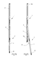
- FIGS. 1a and 1b show the overall view of a first embodiment of a vehicle roof bearing Runge 1, wherein FIG. 1a the device in a first folding position and FIG. 1b in a first unfolded position of the bell crank 2 shows.
- the toggle lever 2 is an arrangement of a first lever member 4, and a second lever member 6.
- the first lever member 4 is pivotally mounted at its upper end to a housing member 8.
- the housing element 8 is part of the rigid body of the stanchion 1, and is z. B. attached to or at the level of the cargo bed of the commercial vehicle.
- the lever member 4 has a handle 10.
- the second lever member 6 is pivotally mounted at its upper end to the first lever member 4 in the region between the two ends thereof.
- the other, lower end of the second lever member 6 is pivotally mounted on a Hubelementabêt 12 a, which is guided up and down movable in the stanchion 1.
- This Hubelementabêt 12a is at its hidden on the drawing, the upper end via a driving coupling with a lifting element 12 connectable, which is guided up and down movable in the stanchion.
- the lifting element 12 supports the vehicle roof.
- Hubelementabites 12 a there is also a take away of the lifting element 12, and thus the roof, which is supported on top of the lifting element 12.
- the lifting element 12 is guided in the longitudinal direction in the housing element 8 and protrudes from the vehicle-fixed housing element 8 substantially with an upper lifting element section 12b, which produces the support to the vehicle roof.
- FIG. 2 shows a detail of the in the FIGS. 1a and 1b shown first embodiment. It shows the first actuating element 14 as a downwardly facing exposed cylinder pin 16 which protrudes from the lifting element 12 within the housing member 8.
- the first lever member 4 of the toggle element 2 can be found in the in FIG. 2 shown detail display in a first Ausklapp position in which the first folding angle ⁇ is still too large for engagement of the second actuating element 18 with the first actuating element 14.
- the second actuating element 18 is in the second Ausklapp position in which it first lever member 4 spans a second folding angle ⁇ .
- FIGS. 3a and 3b show different, the sequence of actuation of the first actuating element 12 by the second actuating element 18, in particular by a web 20 of a U-profile. While the FIG. 3a the first folding angle ⁇ between the longitudinal axis of the first lever member 4 and the longitudinal axis of the housing member 8 is still too large to actuate the cylinder pin 16 shows FIG. 3b both the first lever member 4 in the first folding position, and the second actuating member 18 in the second folding position in which it actuates the cylinder pin 16 by a maximum displacement.
- the FIGS. 3a and 3b further show the fixed to the first lever member 4 first threaded member 21 and the second threaded member 22 of the adjusting device 24th
- FIGS. 4a to 4c show according to the FIGS. 3a and 3b the sequence of actuation of the first actuating element 14 by the second actuating element 18 of a second embodiment, in which the second actuating element 18 has a first contour element 26.
- the contour element 26 can be realized for example by a further threaded element, which in turn allows an adjustment of the position of the second actuating element 18.
- FIGS. 5a and 5b show the overall views in FIG. 1a and FIG. 1b According to the first embodiment, a third embodiment with a chain element 28th
- FIG. 6 shows a detailed view of this third embodiment.
- the chain element 28 consists of two pivotally interconnected chain links 30, wherein the one chain link 30 with the in FIG. 6 unrecognizable cylinder pin 16 and the other chain link 30 is pivotally connected to the housing-fixed adjusting device 24 here.
- the first lever member 4 is formed by the second operating member 18.
- FIGS. 7a to 7c show various the flow of the first actuating element by the second actuating element of this third embodiment.
- Figure 7a is the first lever member 4, the contour of which forms the second actuator 18, still too far out to contact the V-shaped twisted to each other, protruding in the direction of the second actuator 18 chain links 30 of the chain element 28.
- FIG. 7b however, the first lever member 4 in a position in which the second actuator 18, the chain link just touched, but this does not move.
- FIG. 7c shows the third embodiment in the first folding position of the toggle element.
- the contour of the first lever member 4 forming the second actuating element 18 presses the chain links 30 into a substantially line-shaped position, ie nearly aligned in their longitudinal extent, which causes the chain link 30 to expand in the longitudinal direction of the cylinder journal 16, and consequently by the latter Chain link moved, that is actuated.
- the third embodiment also has a second contour element 32 of the housing element 8. This is arranged such that the chain links 30 can not rotate in the opposite direction, ie away from the first lever member 4.
Landscapes
- Engineering & Computer Science (AREA)
- Mechanical Engineering (AREA)
- Chemical & Material Sciences (AREA)
- Combustion & Propulsion (AREA)
- Transportation (AREA)
- Fittings On The Vehicle Exterior For Carrying Loads, And Devices For Holding Or Mounting Articles (AREA)
- Transmission Devices (AREA)
- Body Structure For Vehicles (AREA)
Abstract
Description
- Die Erfindung betrifft eine Vorrichtung zum Anheben und Absenken eines auf teleskopierbaren Rungen abgestützten Dachs eines Nutzfahrzeugs, wobei eine Runge ein Gehäuseelement, ein relativ zu dem Gehäuseelement teleskopierbares Hubelement und einen Kniehebel aufweist, der ein erstes, zwischen einer ersten Einklapp- und einer ersten Ausklapp-Position klappbares und an dem Gehäuseelement angelenktes Hebelglied und ein zweites, mit dem Hubelement verbindbares Hebelglied aufweist, wobei der Kniehebel derart ausgestaltet ist, dass das Anheben des Hubelements durch eine Klappbewegung aus der Einklapp- in die Ausklapp-Position bewirkbar ist, wobei die Runge ferner ein erstes Betätigungselement aufweist, durch dessen Betätigung das Hubelement absenkbar ist, und wobei das erste Hebelglied zur Betätigung des ersten Betätigungselements ein zweites Betätigungselement aufweist.
- Eine als teleskopierbare Runge ausgebildete Vorrichtung mit diesen Merkmalen ist aus der
EP 1 544 087 B1 bekannt. Bestandteile der Runge sind ein Gehäuseelement, welches sich starr gegenüber der Ladefläche des Nutzfahrzeugaufbaus abstützt, ein in dem Gehäuseelement vertikal geführtes Hubelement, dessen oberes Ende gelenkig oder nicht gelenkig mit dem Fahrzeugdach verbunden ist, sowie eine Kniehebelanordnung, mit deren Hilfe sich das Hubelement und damit das Fahrzeugdach in Bezug auf das Gehäuseelement anheben lässt. Die Kniehebelanordnung weist ein an dem Gehäuseelement angelenktes und zu einem Handhebel verlängertes erstes Hebelglied, und ein über eine Kupplung mit dem Hubelement verbindbares, zweites Hebelglied auf. Bei Betätigung der Kniehebelanordnung kommt es über die Kupplung zu einem vertikalen Mitnehmen des Hubelements, und damit zu einem Anheben des Fahrzeugdachs. Zum Absenken des Dachs aus seiner angehobenen Stellung wird ein gesonderter, in einer Ausnehmung der Kniehebelanordnung angeordneter Betätigungshebel in der vollständig eingeklappten Stellung der Kniehebelanordnung aus dieser heraus geschwenkt. Dies hat zur Folge, dass ein Betätigungsarm einen Ventilschaft einer Kolben- und Zylindereinheit nach oben drückt und sich ein Ventil in der Kolben- und Zylindereinheit öffnet. Das Öffnen des Ventils bewirkt eine Relativbewegung zwischen dem Kolben und dem Zylinder, und damit das Absenken des Hubelements und des Dachs. - Die Höhenverstellung eines Nutzfahrzeugdaches erfolgt zur Erleichterung von Be- und Entladevorgängen des Nutzfahrzeuges. Vor einem Beladevorgang wird das Dach durch eine Art Pumpbewegung des Kniehebelmechanismus angehoben, was durch die derart vergrößerte Zuladeöffnung zu einer Erleichterung der Beladung mit großer und/oder sperriger Ladung führt. Ist der Beladevorgang abgeschlossen und die Ladung günstig verteilt, wird das Dach wieder abgesenkt. Als nachteilig hat sich herausgestellt, dass bei dieser Vorrichtung das Anheben und Absenken des Daches unter dem insbesondere im Speditionsgewerbe üblichen Zeitdruck, nicht anwenderfreundlich genug ist.
- Es ist daher die Aufgabe der Erfindung, eine Vorrichtung der eingangs genannten Art bereitzustellen, die sich durch ihre einfache Anwendung auszeichnet.
- Diese Aufgabe wird bei einer Vorrichtung der eingangs genannten Art dadurch gelöst, dass das erste und das zweite Betätigungselement derart angeordnet sind, dass bei einer Klappbewegung des ersten Hebelgliedes aus der ersten Ausklapp-Position in die erste Einklapp-Position das zweite Betätigungselement bereits kurz vor Erreichen der Einklapp-Position durch das erste Betätigungselement betätigbar ist.
- Durch diese Anordnung der Betätigungselemente lassen sich sowohl das Anheben als auch das Absenken des Dachs des Nutzfahrzeugs mit einem einzigen Handgriff zeitsparend ausführen. Die Kniehebelanordnung muss nicht zunächst vollständig eingeklappt werden, um erst anschließend einen in einer Ausnehmung des ersten Hebelgliedes liegenden und somit kleinen, weiteren Betätigungshebel betätigen zu können. Es ist stattdessen möglich, ab einem ersten Klappwinkel von z. B. kleiner als 15° zwischen dem Gehäuseelement und dem ersten Hebelglied das Hubelement abzusenken. Dabei kann sich, muss aber nicht, die Absenkgeschwindigkeit umgekehrt proportional zu dem ersten Klappwinkel verhalten, wodurch sie über eine Betätigung des ersten Hebelglieds steuerbar ist. Die Vorrichtung kann sowohl eigenständig von Beginn an, als auch als Nachrüstung bei bereits vorhandenen Rungen durch Verbindung mit diesen montiert werden.
- Bevorzugt ist das erste Betätigungselement als ein nach unten weisender, zur Betätigung relativ zu dem Hubelement nach oben verschiebbarer Zylinderzapfen ausgestaltet. Ein Zylinder bildet eine stabile und kompakte Standardform, welche einfach, beispielsweise durch Öffnungen weiterer Elemente wie Führungen, zu führen ist. Beispielsweise kann der Zylinderzapfen ein nach unten verlängerter Ventilschaft eines Ventils einer hydraulischen Zylinder-Kolben-Einheit sein, bei der eine Verschiebung nach oben zu einer Öffnung des Ventils führt, was wiederum eine Relativbewegung des Kolben gegenüber dem Zylinder bewirkt.
- In einer bevorzugten Ausführungsform ist das zweite Betätigungselement an dem ersten Hebelglied zwischen einer seine Grundposition bildenden zweiten Ausklapp-Position und einer zweiten Einklapp-Position schwenkbar gelagert, und es weist einen Steg für den Eingriff in das erste Betätigungselement auf. Dabei kann das zweite Betätigungselement beispielweise durch ein Federelement in die zweite Ausklapp-Position gedrückt werden, in welcher sich der Steg von dem ersten Hebelglied in Richtung des Gehäuseelements und somit des ersten Betätigungselements in einem zweiten Klappwinkel abspreizt. Auch ein Steg bildet eine stabile Standardform, welche zum Einen einfach zu fertigen ist und zum Anderen einen zuverlässigen Eingriff mit dem ersten Betätigungselement gewährleisten kann.
- Bei einer weiteren Ausführungsform ist das zweite Betätigungselement derart angeordnet, dass das erste Betätigungselement in der ersten Einklapp-Position betätigbar ist. Dies ermöglicht, dass für ein vollständiges Absenken des Hubelements bis zu seiner unteren Hubbegrenzung das Kniehebelelement lediglich durch eine kurze Bewegung in die erste Einklapp-Position bewegt werden muss. Dies kann geschehen, indem in der ersten Einklapp-Position die beiden Betätigungselemente im Eingriff bleiben, d. h. das erste von dem zweiten Betätigungselement andauernd betätigt, z.B. nach oben verschoben, wird. Im Gegensatz zu der Vorrichtung gemäß
EP 1 544 087 B1 sind ein längeres Halten eines Betätigungshebels durch einen Anwender während des Absenkvorgangs, und ein sich anschließender weiterer Anwendungsschritt, beispielsweise eine Verstauposition des Betätigungshebels, nicht erforderlich. - Um während des Absenkens des Daches eine Höheneinstellung auch in jeder Zwischenhöhe zu ermöglichen, ist es bei einer alternativen Ausführungsform vorteilig, dass das zweite Betätigungselement derart angeordnet ist, dass das erste Betätigungselement in der ersten Einklapp-Position nicht betätigbar ist. Beispielsweise durch eine spezielle Ausgestaltung einer Kontur des ersten und/oder des zweiten Betätigungselements wird der Eingriff der beiden Betätigungselemente in der ersten Einklapp-Position wieder gelöst. Beispielweise kann der Eingriff der Betätigungselemente bei ersten Klappwinkeln von 15° bis 3° bei ersten Klappwinkeln von 2° bis 0° wieder gelöst sein. Dabei kann die zweite Einklapp-Position des zweiten Betätigungselements seitlich versetzt neben dem ersten Betätigungselement angeordnet sein.
- In einer weiteren alternativen Ausführungsform ist das erste Betätigungselement mit einem ersten Ende eines zweigliedrigen Kettenelements verbunden, welches an seinem zweiten Ende schwenkbar und gehäusefest angeordnet ist und bei nicht betätigtem ersten Betätigungselement die zwei Kettenglieder gegeneinender V-förmig in Richtung des ersten Hebelglieds schwenkbar sind, und dass das erste Hebelglied das zweite Betätigungselement bildet, durch welches die verschwenkten Kettenglieder zur Betätigung des ersten Betätigungselements in eine im Wesentlichen längs zueinander ausgewuchteten Position drückbar sind. Das Kettenelement in der im Wesentlichen linienförmigen ausgestreckten Position weist eine größere Ausdehnung in Längsrichtung und damit in Betätigungsrichtung des ersten Betätigungselements auf, als in der zusammengestauchten Position mit zueinander verdrehten Kettengliedern. Die Differenz der Längsausdehnung in Längsrichtung des ersten Betätigungselements zwischen diesen beiden Positionen entspricht dem Betätigungshub des ersten Betätigungselements. Beispielsweise kann eine Kontur des ersten Hebelglieds das zweite Betätigungselement bilden, wobei sobald die Kontur die ihr V-Förmig entgegenragendeden Kettenglieder bei einer Bewegung des ersten Hebelglieds in die erste Einklapp-Position kontaktiert und bewegt, das erste Betätigungselement entsprechend der Streckung der Kettenglieder betätigt wird.
- Von Vorteil ist, wenn die Vorrichtung eine einen Betätigungshubweg des ersten Betätigungselements einstellende Justiervorrichtung aufweist. Beispielsweise über in dem ersten Hebelglied und/oder in dem Gehäuseelement angeordnete Gewindeelemente kann durch Veränderung der Position der Betätigungselemente und/oder des Kettenelements der Betätigungshub variierbar sein. Insbesondere bei längerer Nutzung der Vorrichtung kann eine Nachjustierung aufgrund von sich einstellenden Deformierungen und/oder Abnutzungen nötig werden.
- Weitere Vorteile und Einzelheiten ergeben sich aus der nachfolgenden Beschreibung von Ausführungsbeispielen der Erfindung, wobei auf die Zeichnungen Bezug genommen wird. Darin zeigen:
- Fig. 1a und 1 b
- Gesamtdarstellungen einer ersten Ausführungsform der Vorrichtung mit dem Kniehebel in der ersten Einklapp- und der ersten Ausklapp-Position;
- Fig. 2
- Eine Detaildarstellung der ersten Ausführungsform im unteren Bereich der Vorrichtung;
- Fig. 3a und 3b
- Verschiedene den Ablauf der Betätigung des ersten Betätigungselements durch das zweite Betätigungselements zeigende Detaildarstellungen der ersten Ausführungsform;
- Fig. 4a, 4b und 4c
- Verschiedene, den Ablauf der Betätigung des ersten Betätigungselements durch das zweite Betätigungselements zeigende Detaildarstellungen einer zweiten Ausführungsform;
- Fig. 5a und 5b
- Gesamtdarstellungen einer dritten Ausführungsform mit dem Kniehebel in der ersten Einklapp- und der zweiten Ausklapp-Position;
- Fig. 6
- Eine Detaildarstellung der dritten Ausführungsform;
- Fig. 7a, 7b und 7c
- Verschiedene den Ablauf der Betätigung des ersten Betätigungselements durch das zweite Betätigungselements zeigende Detaildarstellungen der dritten Ausführungsform.
- Die
Figuren 1a und 1b zeigen die Gesamtdarstellung einer ersten Ausführungsform einer ein Fahrzeugdach tragenden Runge 1, wobeiFigur 1a die Vorrichtung in einer ersten Einklapp-Position undFigur 1b in einer ersten Ausklapp-Position des Kniehebels 2 zeigt. Der Kniehebel 2 ist eine Anordnung aus einem ersten Hebelglied 4, und einem zweiten Hebelglied 6. Das erste Hebelglied 4 ist an seinem oberen Ende an einem Gehäuseelement 8 schwenkbar gelagert. Das Gehäuseelement 8 ist Bestandteil des starren Grundkörpers der Runge 1, und ist z. B. an oder in der Höhe der Ladefläche des Nutzfahrzeugs befestigt. - An seinem unteren Ende weist das Hebelglied 4 eine Handhabe 10 auf. Das zweite Hebelglied 6 ist an seinem oberen Ende schwenkbar an dem ersten Hebelglied 4 im Bereich zwischen dessen beiden Enden gelagert. Das andere, untere Ende des zweiten Hebelglieds 6 ist schwenkbar an einem Hubelementabschnitt 12a gelagert, welcher auf- und abbeweglich in der Runge 1 geführt ist. Dieser Hubelementabschnitt 12a ist an seinem auf der Zeichnung verdeckten, oberen Ende über eine Mitnehmerkupplung mit einem Hubelement 12 verbindbar, welches auf- und abbeweglich in der Runge geführt ist. Das Hubelement 12 stützt das Fahrzeugdach ab. Mit dem Anheben des Hebelglieds 6 und des damit gelenkig verbundenen Hubelementabschnitts 12a kommt es zugleich zu einem Mitnehmen des Hubelements 12, und damit des Dachs, welches sich oben auf dem Hubelement 12 abstützt. Das Hubelement 12 ist in der Längsrichtung in dem Gehäuseelement 8 geführt und ragt im Wesentlichen mit einem oberen Hubelementabschnitt 12b, welcher die Abstützung zum Fahrzeugdach herstellt, aus dem fahrzeugfesten Gehäuseelement 8 heraus..
-
Figur 2 zeigt eine Detaildarstellung der in denFiguren 1a und 1b gezeigten ersten Ausführungsform. Es zeigt das erste Betätigungselement 14 als nach unten weisender freiliegender Zylinderzapfen 16, welcher innerhalb des Gehäuseelements 8 aus dem Hubelement 12 hervorragt. Das erste Hebelglied 4 des Kniehebelelements 2 findet sich in der inFigur 2 gezeigten Detaildarstellung in einer ersten Ausklapp-Position, in welcher der erste Klappwinkel α noch zu groß ist für einen Eingriff des zweiten Betätigungselements 18 mit dem ersten Betätigungselement 14. Das zweite Betätigungselement 18 befindet sich in der zweiten Ausklapp-Position, in der es mit dem ersten Hebelglied 4 einen zweiten Klappwinkel β aufspannt. - Die
Figuren 3a und 3b zeigen verschiedene, den Ablauf der Betätigung des ersten Betätigungselements 12 durch das zweite Betätigungselement 18, insbesondere durch einen Steg 20 eines U-Profils. Während dieFigur 3a der erste Klappwinkel α zwischen der Längsachse des ersten Hebelglieds 4 und der Längsachse des Gehäuseelements 8 noch zu groß ist, um den Zylinderzapfen 16 zu betätigen, zeigtFigur 3b sowohl das erste Hebelglied 4 in der ersten Einklapp-Position, als auch das zweite Betätigungselement 18 in der zweiten Einklapp-Position, in welcher dieser den Zylinderzapfen 16 durch eine maximale Verschiebung betätigt. DieFiguren 3a und 3b zeigen ferner das an dem ersten Hebelglied 4 festgelegte erste Gewindeelement 21 sowie das zweite Gewindeelement 22 der Justiervorrichtung 24. - Die
Figuren 4a bis 4c zeigen entsprechend denFiguren 3a und 3b den Ablauf der Betätigung des ersten Betätigungselements 14 durch das zweite Betätigungselement 18 einer zweiten Ausführungsform, bei welcher das zweite Betätigungselement 18 ein erstes Konturelement 26 aufweist. Dies führt dazu, dass in der inFigur 4c gezeigten Position, d. h. in der ersten Einklapp-Position des ersten Hebelglieds 4 und in der zweiten Einklapp-Position des zweiten Betätigungselements 18, der Steg 20 das erste Betätigungselement 14 nicht mehr betätigt, sondern durch in Kontakt des Konturelements 26 mit dem Gehäuseelement 8 das zweite Betätigungselement 18 bei dieser zweiten Ausführungsform weiter eingeklappt wird als in der in denFiguren 3a und 3b gezeigten ersten Ausführungsform, sodass der Steg 20 relativ zu dem Zylinderzapfen 16 seitlich versetzt wird. Das Konturelement 26 kann beispielsweise durch ein weiteres Gewindeelement realisiert werden, was wiederum eine Justierung der Position des zweiten Betätigungselements 18 ermöglicht. -
Figuren 5a und 5b zeigen den Gesamtdarstellungen inFigur 1a und Figur 1b der ersten Ausführungsform entsprechend eine dritte Ausführungsform mit einem Kettenelement 28. -
Figur 6 zeigt eine Detaildarstellung dieser dritten Ausführungsform. Das Kettenelement 28 besteht aus zwei schwenkbar miteinander verbundenen Kettengliedern 30, wobei das eine Kettenglied 30 mit dem inFigur 6 nicht erkennbaren Zylinderzapfen 16 und das andere Kettenglied 30 mit der hier gehäusefesten Justiervorrichtung 24 schwenkbar verbunden ist. Bei der dritten Ausführungsform wird das erste Hebelglied 4 durch das zweite Betätigungselement 18 gebildet. -
Figuren 7a bis 7c zeigen verschiedene den Ablauf des ersten Betätigungselements durch das zweite Betätigungselement dieser dritten Ausführungsform. InFigur 7a ist das erste Hebelglied 4, dessen Kontur das zweite Betätigungselement 18 bildet, noch zu weit ausgeklappt, um die V-förmig zueinander verdrehten, in Richtung des zweiten Betätigungselements 18 herausragenden Kettenglieder 30 des Kettenelements 28 zu kontaktieren.Figur 7b hingegen zeigt das erste Hebelglied 4 in einer Position, in der das zweite Betätigungselement 18 das Kettenglied gerade berührt, jedoch dieses noch nicht bewegt.Figur 7c zeigt die dritte Ausführungsform in der ersten Einklapp-Position des Kniehebelelements. Die das zweite Betätigungselement 18 bildende Kontur des ersten Hebelglieds 4 drückt die Kettenglieder 30 in eine im Wesentlichen linienförmige, d. h. in ihrer Längsausdehnung nahezu fluchtende Position, was zu einer Vergrößerung der Ausdehnung des Kettenglieds 30 in Längsrichtung des Zylinderzapfens 16 bewirkt, und dieser folglich durch das Kettenglied verschoben, d. h. betätigt wird. Die dritte Ausführungsform weist ferner ein zweites Konturelement 32 des Gehäuseelements 8 auf. Dieses ist derart angeordnet, dass die Kettenglieder 30 sich nicht in die entgegengesetzte Richtung, d. h. weg von dem ersten Hebelglied 4, verdrehen können. -
- 1
- Runge
- 2
- Kniehebel, Kniehebelanordnung
- 4
- Erstes Hebelglied
- 6
- Zweites Hebelglied
- 8
- Gehäuseelement
- 10
- Handhabe
- 12
- Hubelement
- 12a
- unterer Hubelementabschnitt
- 12b
- oberer Hubelementabschnitt
- 14
- Erstes Betätigungselement
- 16
- Zylinderzapfen
- 18
- Zweites Betätigungselement
- 20
- Steg
- 21
- Erstes Gewindeelement
- 22
- Zweites Gewindeelement
- 24
- Justiervorrichtung
- 26
- Erstes Konturelement
- 28
- Kettenelement
- 30
- Kettenglied
- 32
- Zweites Konturelement
- α
- Klappwinkel
- β
- Klappwinkel
Claims (7)
- Vorrichtung zum Anheben und Absenken eines auf teleskopierbaren Rungen abgestützten Dachs eines Nutzfahrzeugs, wobei eine Runge (1) ein Gehäuseelement (8), ein relativ zu dem Gehäuseelement (8) teleskopierbares Hubelement (12) und einen Kniehebel (2) aufweist, der ein erstes, zwischen einer ersten Einklapp- und einer ersten Ausklapp-Position klappbares und an dem Gehäuseelement (8) angelenktes Hebelglied (4) und ein zweites, mit dem Hubelement (12) verbindbares Hebelglied (6) aufweist, wobei der Kniehebel (2) derart ausgestaltet ist, dass das Anheben des Hubelements (12) durch eine Klappbewegung aus der Einklapp- in die Ausklapp-Position bewirkbar ist, wobei die Runge (1) ferner ein erstes Betätigungselement (14) aufweist, durch dessen Betätigung das Hubelement (12) absenkbar ist, und wobei das erste Hebelglied (4) zur Betätigung des ersten Betätigungselements (14) ein zweites Betätigungselement (18) aufweist, dadurch gekennzeichnet, dass das erste und das zweite Betätigungselement (14, 18) derart angeordnet sind, dass bei einer Klappbewegung des ersten Hebelgliedes (4) aus der ersten Ausklapp-Position in die erste Einklapp-Position das zweite Betätigungselement (18) bereits kurz vor Erreichen der Einklapp-Position durch das erste Betätigungselement (14) betätigbar ist.
- Vorrichtung nach Anspruch 1, dadurch gekennzeichnet, dass das erste Betätigungselement (14) als ein nach unten weisender, zur Betätigung relativ zu dem Hubelement (12) nach oben verschiebbarer Zylinderzapfen (16) ausgestaltet ist.
- Vorrichtung nach Anspruch 1 oder 2, dadurch gekennzeichnet, dass das zweite Betätigungselement (18) an dem ersten Hebelglied (4) zwischen einer seine Grundposition bildenden zweiten Ausklapp-Position und einer zweiten Einklapp-Position schwenkbar gelagert ist und einen Steg (20) zum Eingriff mit dem ersten Betätigungselement (14) aufweist.
- Vorrichtung nach einem der Ansprüche 1 bis 3, dadurch gekennzeichnet, dass das zweite Betätigungselement (18) derart angeordnet ist, dass das erste Betätigungselement (14) in der ersten Einklapp-Position betätigbar ist.
- Vorrichtung nach einem der Ansprüche 1 bis 3, dadurch gekennzeichnet, dass das zweite Betätigungselement (18) derart angeordnet ist, dass das erste Betätigungselement (14) in der ersten Einklapp-Position nicht im Betätigungssinne betätigbar ist.
- Vorrichtung nach Anspruch 1 oder 2, dadurch gekennzeichnet, dass das erste Betätigungselement (14) mit einem ersten Ende eines zweigliedrigen Kettenelements (28) verbunden ist, welches an seinem zweiten Ende schwenkbar und gehäusefest angeordnet ist und bei nicht betätigtem ersten Betätigungselement (14) die zwei Kettenglieder (30) gegeneinender V-förmig in Richtung des ersten Hebelglieds (4) verschwenkbar sind, und dass das erste Hebelglied (4) das zweite Betätigungselement (18) bildet, durch welches die verschwenkten Kettenglieder (30) zur Betätigung des ersten Betätigungselements (14) in eine im Wesentlichen längs zueinander ausgerichtete Position drückbar sind.
- Vorrichtung nach einem der Ansprüche 1 bis 6, dadurch gekennzeichnet, dass diese ferner eine einen Betätigungshubweg des ersten Betätigungselements (14) einstellende Justiervorrichtung (24) umfasst.
Applications Claiming Priority (1)
| Application Number | Priority Date | Filing Date | Title |
|---|---|---|---|
| DE102010037553A DE102010037553A1 (de) | 2010-09-15 | 2010-09-15 | Vorrichtung zum Anheben und Absenken eines auf teleskopierbaren Rungen abgestützten Daches eines Nutzfahrzeugs |
Publications (3)
| Publication Number | Publication Date |
|---|---|
| EP2431260A2 true EP2431260A2 (de) | 2012-03-21 |
| EP2431260A3 EP2431260A3 (de) | 2015-09-16 |
| EP2431260B1 EP2431260B1 (de) | 2020-01-08 |
Family
ID=44650692
Family Applications (1)
| Application Number | Title | Priority Date | Filing Date |
|---|---|---|---|
| EP11179714.8A Active EP2431260B1 (de) | 2010-09-15 | 2011-09-01 | Vorrichtung zum Anheben und Absenken eines auf teleskopierbaren Rungen abgestützten Dachs eines Nutzfahrzeugs |
Country Status (3)
| Country | Link |
|---|---|
| EP (1) | EP2431260B1 (de) |
| DE (1) | DE102010037553A1 (de) |
| ES (1) | ES2769625T3 (de) |
Cited By (1)
| Publication number | Priority date | Publication date | Assignee | Title |
|---|---|---|---|---|
| DE102013108752A1 (de) | 2013-08-13 | 2015-02-19 | Wihag Fahrzeugbausysteme Gmbh | Vorrichtung zum Anheben und Absenken eines Daches eines Nutzfahrzeuges |
Families Citing this family (1)
| Publication number | Priority date | Publication date | Assignee | Title |
|---|---|---|---|---|
| DE102010050504A1 (de) | 2010-11-08 | 2012-05-10 | F. Hesterberg & Söhne Gmbh & Co. Kg | Vorrichtung zum Anheben und Absenken eines auf teleskopierbaren Rungen abgestützten Daches eines Nutzfahrzeugs |
Citations (1)
| Publication number | Priority date | Publication date | Assignee | Title |
|---|---|---|---|---|
| EP1544087B1 (de) | 2003-12-16 | 2007-10-10 | F. HESTERBERG & SÖHNE GmbH & Co. KG | Vorrichtung zum Anheben und Absenken eines über Rungen abgestützen Daches eines Nutzfahrzeugaufbaus |
Family Cites Families (2)
| Publication number | Priority date | Publication date | Assignee | Title |
|---|---|---|---|---|
| IT208133Z2 (it) * | 1986-10-01 | 1988-04-11 | Viberti Off Spa | Dispositivo di regolazione dell al tezza delle centine trasversali disostegno del telone di un cassone di autoveicolo per trasporto di cose |
| DE29907916U1 (de) * | 1999-05-04 | 1999-07-15 | F. Hesterberg & Söhne GmbH & Co KG, 58256 Ennepetal | Mechanische Vorrichtung zum Heben eines auf Eckrungen ruhenden Dachs eines Nutzfahrzeugaufbaus |
-
2010
- 2010-09-15 DE DE102010037553A patent/DE102010037553A1/de not_active Withdrawn
-
2011
- 2011-09-01 ES ES11179714T patent/ES2769625T3/es active Active
- 2011-09-01 EP EP11179714.8A patent/EP2431260B1/de active Active
Patent Citations (1)
| Publication number | Priority date | Publication date | Assignee | Title |
|---|---|---|---|---|
| EP1544087B1 (de) | 2003-12-16 | 2007-10-10 | F. HESTERBERG & SÖHNE GmbH & Co. KG | Vorrichtung zum Anheben und Absenken eines über Rungen abgestützen Daches eines Nutzfahrzeugaufbaus |
Cited By (1)
| Publication number | Priority date | Publication date | Assignee | Title |
|---|---|---|---|---|
| DE102013108752A1 (de) | 2013-08-13 | 2015-02-19 | Wihag Fahrzeugbausysteme Gmbh | Vorrichtung zum Anheben und Absenken eines Daches eines Nutzfahrzeuges |
Also Published As
| Publication number | Publication date |
|---|---|
| ES2769625T3 (es) | 2020-06-26 |
| EP2431260B1 (de) | 2020-01-08 |
| DE102010037553A1 (de) | 2012-03-15 |
| EP2431260A3 (de) | 2015-09-16 |
Similar Documents
| Publication | Publication Date | Title |
|---|---|---|
| EP2176485B1 (de) | Beschlag mit relativ zueinander schwenkbaren beschlagteilen und mit einer verzögerungsvorrichtung | |
| EP0336088B1 (de) | Schwenkunterstützung eines den unteren Abschluss eines Klappverdecks bildenden Dachhauthaltebügels | |
| EP2139804B1 (de) | Verstellmechanismus für eine seilwinde | |
| DE3318550A1 (de) | Hubvorrichtung, insbesondere hebebuehne fuer kraftfahrzeuge | |
| EP3446905B1 (de) | Aufstellbares fahrzeugdach | |
| EP2946983A1 (de) | Flurförderzeug mit rampenhubfunktion | |
| EP1084601B1 (de) | Seitenstrebe für einen Unterlenker eines Traktors | |
| EP2799283B1 (de) | Lastentransportfahrzeug mit einem Wechselbehälter und einem Hubgerät für den Wechselbehälter | |
| EP2431260B1 (de) | Vorrichtung zum Anheben und Absenken eines auf teleskopierbaren Rungen abgestützten Dachs eines Nutzfahrzeugs | |
| EP2030772A2 (de) | Sicherheitseinrichtung an Umformmaschinen | |
| DE2843587C2 (de) | Hebevorrichtung mit einer um eine lotrechte Achse drehbaren Plattform für einen Ausleger | |
| EP3884743A1 (de) | Anbaudrehpflug | |
| DE3333231A1 (de) | Anordnung zur laengenverstellung einer zuggabel fuer einen fahrzeuganhaenger | |
| DE19650577B4 (de) | Betätigungsvorrichtung für eine Kraftfahrzeugkupplung | |
| AT14798U1 (de) | Faltbare abklappbare Rampe an Fahrzeugen | |
| EP4360417A1 (de) | Landwirtschaftliches arbeitsgerät zum bearbeiten eines bodens | |
| EP0733585A2 (de) | Ladekran | |
| DE1680318B1 (de) | Vorrichtung zur Bremsung einer Landzugmaschine und ihres Anhaengers | |
| DE2903408A1 (de) | Verfahren zum drehen eines drehpfluges mittels einer hydraulischen drehvorrichtung und nach dem verfahren arbeitende drehvorrichtung | |
| DE3930529A1 (de) | Hydraulischer scherenhubtisch | |
| DE2621150C2 (de) | ||
| EP3613634A1 (de) | Hebevorrichtung | |
| AT411592B (de) | Spreizvorrichtung | |
| DE10036119B4 (de) | Nietsetzgerät | |
| DE10258939B4 (de) | Betätigungseinrichtung für eine Kraftfahrzeugkupplung |
Legal Events
| Date | Code | Title | Description |
|---|---|---|---|
| PUAI | Public reference made under article 153(3) epc to a published international application that has entered the european phase |
Free format text: ORIGINAL CODE: 0009012 |
|
| AK | Designated contracting states |
Kind code of ref document: A2 Designated state(s): AL AT BE BG CH CY CZ DE DK EE ES FI FR GB GR HR HU IE IS IT LI LT LU LV MC MK MT NL NO PL PT RO RS SE SI SK SM TR |
|
| AX | Request for extension of the european patent |
Extension state: BA ME |
|
| PUAL | Search report despatched |
Free format text: ORIGINAL CODE: 0009013 |
|
| AK | Designated contracting states |
Kind code of ref document: A3 Designated state(s): AL AT BE BG CH CY CZ DE DK EE ES FI FR GB GR HR HU IE IS IT LI LT LU LV MC MK MT NL NO PL PT RO RS SE SI SK SM TR |
|
| AX | Request for extension of the european patent |
Extension state: BA ME |
|
| RIC1 | Information provided on ipc code assigned before grant |
Ipc: B60J 7/16 20060101ALI20150810BHEP Ipc: B62D 33/02 20060101AFI20150810BHEP |
|
| 17P | Request for examination filed |
Effective date: 20160308 |
|
| RBV | Designated contracting states (corrected) |
Designated state(s): AL AT BE BG CH CY CZ DE DK EE ES FI FR GB GR HR HU IE IS IT LI LT LU LV MC MK MT NL NO PL PT RO RS SE SI SK SM TR |
|
| STAA | Information on the status of an ep patent application or granted ep patent |
Free format text: STATUS: EXAMINATION IS IN PROGRESS |
|
| 17Q | First examination report despatched |
Effective date: 20181221 |
|
| GRAP | Despatch of communication of intention to grant a patent |
Free format text: ORIGINAL CODE: EPIDOSNIGR1 |
|
| STAA | Information on the status of an ep patent application or granted ep patent |
Free format text: STATUS: GRANT OF PATENT IS INTENDED |
|
| INTG | Intention to grant announced |
Effective date: 20190823 |
|
| GRAS | Grant fee paid |
Free format text: ORIGINAL CODE: EPIDOSNIGR3 |
|
| GRAA | (expected) grant |
Free format text: ORIGINAL CODE: 0009210 |
|
| STAA | Information on the status of an ep patent application or granted ep patent |
Free format text: STATUS: THE PATENT HAS BEEN GRANTED |
|
| AK | Designated contracting states |
Kind code of ref document: B1 Designated state(s): AL AT BE BG CH CY CZ DE DK EE ES FI FR GB GR HR HU IE IS IT LI LT LU LV MC MK MT NL NO PL PT RO RS SE SI SK SM TR |
|
| REG | Reference to a national code |
Ref country code: GB Ref legal event code: FG4D Free format text: NOT ENGLISH |
|
| REG | Reference to a national code |
Ref country code: CH Ref legal event code: EP |
|
| REG | Reference to a national code |
Ref country code: DE Ref legal event code: R096 Ref document number: 502011016377 Country of ref document: DE |
|
| REG | Reference to a national code |
Ref country code: IE Ref legal event code: FG4D Free format text: LANGUAGE OF EP DOCUMENT: GERMAN |
|
| REG | Reference to a national code |
Ref country code: AT Ref legal event code: REF Ref document number: 1222354 Country of ref document: AT Kind code of ref document: T Effective date: 20200215 |
|
| REG | Reference to a national code |
Ref country code: NL Ref legal event code: MP Effective date: 20200108 |
|
| REG | Reference to a national code |
Ref country code: ES Ref legal event code: FG2A Ref document number: 2769625 Country of ref document: ES Kind code of ref document: T3 Effective date: 20200626 |
|
| REG | Reference to a national code |
Ref country code: LT Ref legal event code: MG4D |
|
| PG25 | Lapsed in a contracting state [announced via postgrant information from national office to epo] |
Ref country code: NO Free format text: LAPSE BECAUSE OF FAILURE TO SUBMIT A TRANSLATION OF THE DESCRIPTION OR TO PAY THE FEE WITHIN THE PRESCRIBED TIME-LIMIT Effective date: 20200408 Ref country code: PT Free format text: LAPSE BECAUSE OF FAILURE TO SUBMIT A TRANSLATION OF THE DESCRIPTION OR TO PAY THE FEE WITHIN THE PRESCRIBED TIME-LIMIT Effective date: 20200531 Ref country code: RS Free format text: LAPSE BECAUSE OF FAILURE TO SUBMIT A TRANSLATION OF THE DESCRIPTION OR TO PAY THE FEE WITHIN THE PRESCRIBED TIME-LIMIT Effective date: 20200108 Ref country code: FI Free format text: LAPSE BECAUSE OF FAILURE TO SUBMIT A TRANSLATION OF THE DESCRIPTION OR TO PAY THE FEE WITHIN THE PRESCRIBED TIME-LIMIT Effective date: 20200108 Ref country code: NL Free format text: LAPSE BECAUSE OF FAILURE TO SUBMIT A TRANSLATION OF THE DESCRIPTION OR TO PAY THE FEE WITHIN THE PRESCRIBED TIME-LIMIT Effective date: 20200108 Ref country code: LT Free format text: LAPSE BECAUSE OF FAILURE TO SUBMIT A TRANSLATION OF THE DESCRIPTION OR TO PAY THE FEE WITHIN THE PRESCRIBED TIME-LIMIT Effective date: 20200108 |
|
| PG25 | Lapsed in a contracting state [announced via postgrant information from national office to epo] |
Ref country code: BG Free format text: LAPSE BECAUSE OF FAILURE TO SUBMIT A TRANSLATION OF THE DESCRIPTION OR TO PAY THE FEE WITHIN THE PRESCRIBED TIME-LIMIT Effective date: 20200408 Ref country code: IS Free format text: LAPSE BECAUSE OF FAILURE TO SUBMIT A TRANSLATION OF THE DESCRIPTION OR TO PAY THE FEE WITHIN THE PRESCRIBED TIME-LIMIT Effective date: 20200508 Ref country code: GR Free format text: LAPSE BECAUSE OF FAILURE TO SUBMIT A TRANSLATION OF THE DESCRIPTION OR TO PAY THE FEE WITHIN THE PRESCRIBED TIME-LIMIT Effective date: 20200409 Ref country code: SE Free format text: LAPSE BECAUSE OF FAILURE TO SUBMIT A TRANSLATION OF THE DESCRIPTION OR TO PAY THE FEE WITHIN THE PRESCRIBED TIME-LIMIT Effective date: 20200108 Ref country code: LV Free format text: LAPSE BECAUSE OF FAILURE TO SUBMIT A TRANSLATION OF THE DESCRIPTION OR TO PAY THE FEE WITHIN THE PRESCRIBED TIME-LIMIT Effective date: 20200108 Ref country code: HR Free format text: LAPSE BECAUSE OF FAILURE TO SUBMIT A TRANSLATION OF THE DESCRIPTION OR TO PAY THE FEE WITHIN THE PRESCRIBED TIME-LIMIT Effective date: 20200108 |
|
| REG | Reference to a national code |
Ref country code: DE Ref legal event code: R097 Ref document number: 502011016377 Country of ref document: DE |
|
| PG25 | Lapsed in a contracting state [announced via postgrant information from national office to epo] |
Ref country code: SK Free format text: LAPSE BECAUSE OF FAILURE TO SUBMIT A TRANSLATION OF THE DESCRIPTION OR TO PAY THE FEE WITHIN THE PRESCRIBED TIME-LIMIT Effective date: 20200108 Ref country code: SM Free format text: LAPSE BECAUSE OF FAILURE TO SUBMIT A TRANSLATION OF THE DESCRIPTION OR TO PAY THE FEE WITHIN THE PRESCRIBED TIME-LIMIT Effective date: 20200108 Ref country code: CZ Free format text: LAPSE BECAUSE OF FAILURE TO SUBMIT A TRANSLATION OF THE DESCRIPTION OR TO PAY THE FEE WITHIN THE PRESCRIBED TIME-LIMIT Effective date: 20200108 Ref country code: DK Free format text: LAPSE BECAUSE OF FAILURE TO SUBMIT A TRANSLATION OF THE DESCRIPTION OR TO PAY THE FEE WITHIN THE PRESCRIBED TIME-LIMIT Effective date: 20200108 Ref country code: RO Free format text: LAPSE BECAUSE OF FAILURE TO SUBMIT A TRANSLATION OF THE DESCRIPTION OR TO PAY THE FEE WITHIN THE PRESCRIBED TIME-LIMIT Effective date: 20200108 Ref country code: EE Free format text: LAPSE BECAUSE OF FAILURE TO SUBMIT A TRANSLATION OF THE DESCRIPTION OR TO PAY THE FEE WITHIN THE PRESCRIBED TIME-LIMIT Effective date: 20200108 |
|
| PLBE | No opposition filed within time limit |
Free format text: ORIGINAL CODE: 0009261 |
|
| STAA | Information on the status of an ep patent application or granted ep patent |
Free format text: STATUS: NO OPPOSITION FILED WITHIN TIME LIMIT |
|
| 26N | No opposition filed |
Effective date: 20201009 |
|
| PG25 | Lapsed in a contracting state [announced via postgrant information from national office to epo] |
Ref country code: PL Free format text: LAPSE BECAUSE OF FAILURE TO SUBMIT A TRANSLATION OF THE DESCRIPTION OR TO PAY THE FEE WITHIN THE PRESCRIBED TIME-LIMIT Effective date: 20200108 Ref country code: SI Free format text: LAPSE BECAUSE OF FAILURE TO SUBMIT A TRANSLATION OF THE DESCRIPTION OR TO PAY THE FEE WITHIN THE PRESCRIBED TIME-LIMIT Effective date: 20200108 |
|
| PG25 | Lapsed in a contracting state [announced via postgrant information from national office to epo] |
Ref country code: MC Free format text: LAPSE BECAUSE OF FAILURE TO SUBMIT A TRANSLATION OF THE DESCRIPTION OR TO PAY THE FEE WITHIN THE PRESCRIBED TIME-LIMIT Effective date: 20200108 |
|
| REG | Reference to a national code |
Ref country code: CH Ref legal event code: PL |
|
| PG25 | Lapsed in a contracting state [announced via postgrant information from national office to epo] |
Ref country code: LU Free format text: LAPSE BECAUSE OF NON-PAYMENT OF DUE FEES Effective date: 20200901 |
|
| PG25 | Lapsed in a contracting state [announced via postgrant information from national office to epo] |
Ref country code: CH Free format text: LAPSE BECAUSE OF NON-PAYMENT OF DUE FEES Effective date: 20200930 Ref country code: IE Free format text: LAPSE BECAUSE OF NON-PAYMENT OF DUE FEES Effective date: 20200901 Ref country code: LI Free format text: LAPSE BECAUSE OF NON-PAYMENT OF DUE FEES Effective date: 20200930 |
|
| REG | Reference to a national code |
Ref country code: AT Ref legal event code: MM01 Ref document number: 1222354 Country of ref document: AT Kind code of ref document: T Effective date: 20200901 |
|
| REG | Reference to a national code |
Ref country code: DE Ref legal event code: R082 Ref document number: 502011016377 Country of ref document: DE Representative=s name: JANKE SCHOLL PATENTANWAELTE PARTG MBB, DE |
|
| PG25 | Lapsed in a contracting state [announced via postgrant information from national office to epo] |
Ref country code: AT Free format text: LAPSE BECAUSE OF NON-PAYMENT OF DUE FEES Effective date: 20200901 |
|
| PG25 | Lapsed in a contracting state [announced via postgrant information from national office to epo] |
Ref country code: MT Free format text: LAPSE BECAUSE OF FAILURE TO SUBMIT A TRANSLATION OF THE DESCRIPTION OR TO PAY THE FEE WITHIN THE PRESCRIBED TIME-LIMIT Effective date: 20200108 Ref country code: CY Free format text: LAPSE BECAUSE OF FAILURE TO SUBMIT A TRANSLATION OF THE DESCRIPTION OR TO PAY THE FEE WITHIN THE PRESCRIBED TIME-LIMIT Effective date: 20200108 |
|
| PG25 | Lapsed in a contracting state [announced via postgrant information from national office to epo] |
Ref country code: MK Free format text: LAPSE BECAUSE OF FAILURE TO SUBMIT A TRANSLATION OF THE DESCRIPTION OR TO PAY THE FEE WITHIN THE PRESCRIBED TIME-LIMIT Effective date: 20200108 Ref country code: AL Free format text: LAPSE BECAUSE OF FAILURE TO SUBMIT A TRANSLATION OF THE DESCRIPTION OR TO PAY THE FEE WITHIN THE PRESCRIBED TIME-LIMIT Effective date: 20200108 |
|
| PGFP | Annual fee paid to national office [announced via postgrant information from national office to epo] |
Ref country code: DE Payment date: 20250917 Year of fee payment: 15 |
|
| PGFP | Annual fee paid to national office [announced via postgrant information from national office to epo] |
Ref country code: TR Payment date: 20250828 Year of fee payment: 15 |
|
| PGFP | Annual fee paid to national office [announced via postgrant information from national office to epo] |
Ref country code: GB Payment date: 20250923 Year of fee payment: 15 Ref country code: BE Payment date: 20250919 Year of fee payment: 15 |
|
| PGFP | Annual fee paid to national office [announced via postgrant information from national office to epo] |
Ref country code: FR Payment date: 20250925 Year of fee payment: 15 |
|
| PGFP | Annual fee paid to national office [announced via postgrant information from national office to epo] |
Ref country code: IT Payment date: 20250930 Year of fee payment: 15 |
|
| PGFP | Annual fee paid to national office [announced via postgrant information from national office to epo] |
Ref country code: ES Payment date: 20251020 Year of fee payment: 15 |