EP2427603B1 - Ermüdungsfestes fundament - Google Patents
Ermüdungsfestes fundament Download PDFInfo
- Publication number
- EP2427603B1 EP2427603B1 EP10781394.1A EP10781394A EP2427603B1 EP 2427603 B1 EP2427603 B1 EP 2427603B1 EP 10781394 A EP10781394 A EP 10781394A EP 2427603 B1 EP2427603 B1 EP 2427603B1
- Authority
- EP
- European Patent Office
- Prior art keywords
- pedestal
- foundation
- slab
- ribs
- rib
- Prior art date
- Legal status (The legal status is an assumption and is not a legal conclusion. Google has not performed a legal analysis and makes no representation as to the accuracy of the status listed.)
- Revoked
Links
- NJPPVKZQTLUDBO-UHFFFAOYSA-N novaluron Chemical compound C1=C(Cl)C(OC(F)(F)C(OC(F)(F)F)F)=CC=C1NC(=O)NC(=O)C1=C(F)C=CC=C1F NJPPVKZQTLUDBO-UHFFFAOYSA-N 0.000 claims description 315
- 239000004567 concrete Substances 0.000 claims description 154
- 238000000034 method Methods 0.000 claims description 33
- 239000011440 grout Substances 0.000 claims description 15
- 239000000463 material Substances 0.000 claims description 11
- 230000003014 reinforcing effect Effects 0.000 description 82
- 238000010276 construction Methods 0.000 description 74
- 210000002435 tendon Anatomy 0.000 description 53
- 238000013461 design Methods 0.000 description 33
- 238000007906 compression Methods 0.000 description 32
- 238000011065 in-situ storage Methods 0.000 description 30
- 230000006835 compression Effects 0.000 description 22
- 238000009434 installation Methods 0.000 description 22
- 239000002689 soil Substances 0.000 description 21
- 239000011178 precast concrete Substances 0.000 description 19
- 239000003351 stiffener Substances 0.000 description 13
- 230000008901 benefit Effects 0.000 description 12
- 238000004227 thermal cracking Methods 0.000 description 11
- 239000011435 rock Substances 0.000 description 10
- 230000036961 partial effect Effects 0.000 description 9
- 239000007787 solid Substances 0.000 description 9
- 238000012546 transfer Methods 0.000 description 9
- 229910000831 Steel Inorganic materials 0.000 description 8
- 230000006870 function Effects 0.000 description 8
- 230000005484 gravity Effects 0.000 description 8
- 239000010959 steel Substances 0.000 description 8
- 230000009471 action Effects 0.000 description 7
- 239000002131 composite material Substances 0.000 description 7
- 230000036571 hydration Effects 0.000 description 7
- 238000006703 hydration reaction Methods 0.000 description 7
- 239000002184 metal Substances 0.000 description 7
- 230000002787 reinforcement Effects 0.000 description 7
- 238000005452 bending Methods 0.000 description 6
- 230000007246 mechanism Effects 0.000 description 6
- 230000002829 reductive effect Effects 0.000 description 6
- 230000009172 bursting Effects 0.000 description 5
- 238000005266 casting Methods 0.000 description 5
- 230000007797 corrosion Effects 0.000 description 5
- 238000005260 corrosion Methods 0.000 description 5
- XLYOFNOQVPJJNP-UHFFFAOYSA-N water Substances O XLYOFNOQVPJJNP-UHFFFAOYSA-N 0.000 description 5
- 229910001294 Reinforcing steel Inorganic materials 0.000 description 4
- 238000003491 array Methods 0.000 description 4
- 238000009412 basement excavation Methods 0.000 description 4
- 230000017525 heat dissipation Effects 0.000 description 4
- 239000011159 matrix material Substances 0.000 description 4
- 230000007935 neutral effect Effects 0.000 description 4
- 239000007767 bonding agent Substances 0.000 description 3
- 238000006243 chemical reaction Methods 0.000 description 3
- 238000004519 manufacturing process Methods 0.000 description 3
- 239000012528 membrane Substances 0.000 description 3
- 239000000203 mixture Substances 0.000 description 3
- 239000011513 prestressed concrete Substances 0.000 description 3
- 230000008569 process Effects 0.000 description 3
- 230000007704 transition Effects 0.000 description 3
- 239000004593 Epoxy Substances 0.000 description 2
- 230000002159 abnormal effect Effects 0.000 description 2
- 239000004568 cement Substances 0.000 description 2
- 230000008859 change Effects 0.000 description 2
- 238000004891 communication Methods 0.000 description 2
- 230000001186 cumulative effect Effects 0.000 description 2
- 238000010586 diagram Methods 0.000 description 2
- 238000004821 distillation Methods 0.000 description 2
- 238000009826 distribution Methods 0.000 description 2
- 231100001261 hazardous Toxicity 0.000 description 2
- 230000006872 improvement Effects 0.000 description 2
- 238000005304 joining Methods 0.000 description 2
- 230000004048 modification Effects 0.000 description 2
- 238000012986 modification Methods 0.000 description 2
- 230000009467 reduction Effects 0.000 description 2
- 239000011150 reinforced concrete Substances 0.000 description 2
- 239000004575 stone Substances 0.000 description 2
- 238000005303 weighing Methods 0.000 description 2
- 239000004606 Fillers/Extenders Substances 0.000 description 1
- 239000004237 Ponceau 6R Substances 0.000 description 1
- 229920006328 Styrofoam Polymers 0.000 description 1
- 208000027418 Wounds and injury Diseases 0.000 description 1
- 230000000712 assembly Effects 0.000 description 1
- 238000000429 assembly Methods 0.000 description 1
- 238000005056 compaction Methods 0.000 description 1
- 230000001010 compromised effect Effects 0.000 description 1
- 239000004035 construction material Substances 0.000 description 1
- 238000001816 cooling Methods 0.000 description 1
- 238000005336 cracking Methods 0.000 description 1
- 230000006378 damage Effects 0.000 description 1
- 230000003247 decreasing effect Effects 0.000 description 1
- 230000000994 depressogenic effect Effects 0.000 description 1
- 230000000694 effects Effects 0.000 description 1
- 238000005538 encapsulation Methods 0.000 description 1
- 239000000835 fiber Substances 0.000 description 1
- 238000007710 freezing Methods 0.000 description 1
- 230000008014 freezing Effects 0.000 description 1
- 239000003673 groundwater Substances 0.000 description 1
- 208000014674 injury Diseases 0.000 description 1
- 238000005457 optimization Methods 0.000 description 1
- 238000013021 overheating Methods 0.000 description 1
- 239000004014 plasticizer Substances 0.000 description 1
- 238000002360 preparation method Methods 0.000 description 1
- 230000001681 protective effect Effects 0.000 description 1
- 230000008439 repair process Effects 0.000 description 1
- 230000003252 repetitive effect Effects 0.000 description 1
- 238000004513 sizing Methods 0.000 description 1
- 125000006850 spacer group Chemical group 0.000 description 1
- 239000008261 styrofoam Substances 0.000 description 1
- 238000012360 testing method Methods 0.000 description 1
Images


Classifications
-
- E—FIXED CONSTRUCTIONS
- E02—HYDRAULIC ENGINEERING; FOUNDATIONS; SOIL SHIFTING
- E02D—FOUNDATIONS; EXCAVATIONS; EMBANKMENTS; UNDERGROUND OR UNDERWATER STRUCTURES
- E02D27/00—Foundations as substructures
- E02D27/32—Foundations for special purposes
- E02D27/42—Foundations for poles, masts or chimneys
- E02D27/425—Foundations for poles, masts or chimneys specially adapted for wind motors masts
-
- E—FIXED CONSTRUCTIONS
- E02—HYDRAULIC ENGINEERING; FOUNDATIONS; SOIL SHIFTING
- E02B—HYDRAULIC ENGINEERING
- E02B17/00—Artificial islands mounted on piles or like supports, e.g. platforms on raisable legs or offshore constructions; Construction methods therefor
- E02B17/02—Artificial islands mounted on piles or like supports, e.g. platforms on raisable legs or offshore constructions; Construction methods therefor placed by lowering the supporting construction to the bottom, e.g. with subsequent fixing thereto
- E02B17/025—Reinforced concrete structures
-
- E—FIXED CONSTRUCTIONS
- E02—HYDRAULIC ENGINEERING; FOUNDATIONS; SOIL SHIFTING
- E02D—FOUNDATIONS; EXCAVATIONS; EMBANKMENTS; UNDERGROUND OR UNDERWATER STRUCTURES
- E02D27/00—Foundations as substructures
- E02D27/32—Foundations for special purposes
- E02D27/42—Foundations for poles, masts or chimneys
-
- E—FIXED CONSTRUCTIONS
- E02—HYDRAULIC ENGINEERING; FOUNDATIONS; SOIL SHIFTING
- E02D—FOUNDATIONS; EXCAVATIONS; EMBANKMENTS; UNDERGROUND OR UNDERWATER STRUCTURES
- E02D27/00—Foundations as substructures
- E02D27/32—Foundations for special purposes
- E02D27/52—Submerged foundations, i.e. submerged in open water
-
- F—MECHANICAL ENGINEERING; LIGHTING; HEATING; WEAPONS; BLASTING
- F03—MACHINES OR ENGINES FOR LIQUIDS; WIND, SPRING, OR WEIGHT MOTORS; PRODUCING MECHANICAL POWER OR A REACTIVE PROPULSIVE THRUST, NOT OTHERWISE PROVIDED FOR
- F03D—WIND MOTORS
- F03D13/00—Assembly, mounting or commissioning of wind motors; Arrangements specially adapted for transporting wind motor components
- F03D13/20—Arrangements for mounting or supporting wind motors; Masts or towers for wind motors
- F03D13/22—Foundations specially adapted for wind motors
-
- E—FIXED CONSTRUCTIONS
- E02—HYDRAULIC ENGINEERING; FOUNDATIONS; SOIL SHIFTING
- E02B—HYDRAULIC ENGINEERING
- E02B17/00—Artificial islands mounted on piles or like supports, e.g. platforms on raisable legs or offshore constructions; Construction methods therefor
- E02B2017/0039—Methods for placing the offshore structure
-
- E—FIXED CONSTRUCTIONS
- E02—HYDRAULIC ENGINEERING; FOUNDATIONS; SOIL SHIFTING
- E02B—HYDRAULIC ENGINEERING
- E02B17/00—Artificial islands mounted on piles or like supports, e.g. platforms on raisable legs or offshore constructions; Construction methods therefor
- E02B2017/0056—Platforms with supporting legs
- E02B2017/006—Platforms with supporting legs with lattice style supporting legs
-
- E—FIXED CONSTRUCTIONS
- E02—HYDRAULIC ENGINEERING; FOUNDATIONS; SOIL SHIFTING
- E02B—HYDRAULIC ENGINEERING
- E02B17/00—Artificial islands mounted on piles or like supports, e.g. platforms on raisable legs or offshore constructions; Construction methods therefor
- E02B2017/0056—Platforms with supporting legs
- E02B2017/0065—Monopile structures
-
- E—FIXED CONSTRUCTIONS
- E02—HYDRAULIC ENGINEERING; FOUNDATIONS; SOIL SHIFTING
- E02B—HYDRAULIC ENGINEERING
- E02B17/00—Artificial islands mounted on piles or like supports, e.g. platforms on raisable legs or offshore constructions; Construction methods therefor
- E02B2017/0091—Offshore structures for wind turbines
-
- F—MECHANICAL ENGINEERING; LIGHTING; HEATING; WEAPONS; BLASTING
- F05—INDEXING SCHEMES RELATING TO ENGINES OR PUMPS IN VARIOUS SUBCLASSES OF CLASSES F01-F04
- F05B—INDEXING SCHEME RELATING TO WIND, SPRING, WEIGHT, INERTIA OR LIKE MOTORS, TO MACHINES OR ENGINES FOR LIQUIDS COVERED BY SUBCLASSES F03B, F03D AND F03G
- F05B2240/00—Components
- F05B2240/90—Mounting on supporting structures or systems
- F05B2240/91—Mounting on supporting structures or systems on a stationary structure
- F05B2240/912—Mounting on supporting structures or systems on a stationary structure on a tower
-
- Y—GENERAL TAGGING OF NEW TECHNOLOGICAL DEVELOPMENTS; GENERAL TAGGING OF CROSS-SECTIONAL TECHNOLOGIES SPANNING OVER SEVERAL SECTIONS OF THE IPC; TECHNICAL SUBJECTS COVERED BY FORMER USPC CROSS-REFERENCE ART COLLECTIONS [XRACs] AND DIGESTS
- Y02—TECHNOLOGIES OR APPLICATIONS FOR MITIGATION OR ADAPTATION AGAINST CLIMATE CHANGE
- Y02B—CLIMATE CHANGE MITIGATION TECHNOLOGIES RELATED TO BUILDINGS, e.g. HOUSING, HOUSE APPLIANCES OR RELATED END-USER APPLICATIONS
- Y02B10/00—Integration of renewable energy sources in buildings
- Y02B10/30—Wind power
-
- Y—GENERAL TAGGING OF NEW TECHNOLOGICAL DEVELOPMENTS; GENERAL TAGGING OF CROSS-SECTIONAL TECHNOLOGIES SPANNING OVER SEVERAL SECTIONS OF THE IPC; TECHNICAL SUBJECTS COVERED BY FORMER USPC CROSS-REFERENCE ART COLLECTIONS [XRACs] AND DIGESTS
- Y02—TECHNOLOGIES OR APPLICATIONS FOR MITIGATION OR ADAPTATION AGAINST CLIMATE CHANGE
- Y02E—REDUCTION OF GREENHOUSE GAS [GHG] EMISSIONS, RELATED TO ENERGY GENERATION, TRANSMISSION OR DISTRIBUTION
- Y02E10/00—Energy generation through renewable energy sources
- Y02E10/70—Wind energy
- Y02E10/72—Wind turbines with rotation axis in wind direction
-
- Y—GENERAL TAGGING OF NEW TECHNOLOGICAL DEVELOPMENTS; GENERAL TAGGING OF CROSS-SECTIONAL TECHNOLOGIES SPANNING OVER SEVERAL SECTIONS OF THE IPC; TECHNICAL SUBJECTS COVERED BY FORMER USPC CROSS-REFERENCE ART COLLECTIONS [XRACs] AND DIGESTS
- Y02—TECHNOLOGIES OR APPLICATIONS FOR MITIGATION OR ADAPTATION AGAINST CLIMATE CHANGE
- Y02E—REDUCTION OF GREENHOUSE GAS [GHG] EMISSIONS, RELATED TO ENERGY GENERATION, TRANSMISSION OR DISTRIBUTION
- Y02E10/00—Energy generation through renewable energy sources
- Y02E10/70—Wind energy
- Y02E10/728—Onshore wind turbines
Definitions
- This invention relates to building fatigue resistant foundations for supporting columns, towers and structures under heavy cyclical loads such as for onshore and offshore wind turbine towers such as generally known from the document US 2008/0072511 A1 .
- Wind turbine support structures are subjected to high cyclical loading with number of load cycles up to 10 9 . Therefore, the fatigue design becomes more important for concrete construction and the influence of multi-stage and multi-axial fatigue loading have to be considered.
- Studies have recommended modification of the design rules for concrete construction of wind turbine foundations in order to consider the influence of multi-axial loading.
- Wind turbine manufacturers have successfully developed large wind turbines with rated power ranging from 1.5 to 10 MW, for onshore and offshore installations.
- the E-126 model turbine by Enercon with a 7 MW rated power required a 29 meter diameter circular foundation with 1,400 cubic meters of concrete and 120 tons of rebar.
- the RePower 5M turbine with a 5MW rated power required a 23 meter diameter circular foundation with 1,300 cubic meters of concrete and 180 tons of rebar.
- the task of building such large foundations is daunting and requires a great deal of construction planning and logistics.
- the proposed foundation designs and their associated construction methods provide cost-effective solutions for such challenging foundation projects.
- the present invention improves the geometry of the foundation in order to enhance dissipation conditions for the typical temperature rise due to heat of hydration after casting and also provides a cost effective fatigue resistant design.
- Conventional gravity style foundations for large wind turbines usually comprise a large, thick, horizontal, heavily reinforced cast in situ concrete base; and a vertical cast in situ cylindrical pedestal installed over the base. There are several problems typically encountered during the construction of such foundations.
- Fatigue resistance of such conventional footings is achieved by over sizing the structural concrete elements and the reinforcing elements such that the resulting stress amplitudes are small enough for the structural elements to pass fatigue design checks.
- the main problem is the daunting task of managing large continuous concrete pours, which require sophisticated planning and coordination in order to pour large amounts of concrete per footing, in one continuous pour, without having any cold joints within the pour.
- Another problem is logistics coordinating with multiple local batch plants the delivery plan of the large number of concrete trucks to the job site in a timely and organized manner.
- a further problem is the complexity of installing the rebar assembly into the foundation which requires assembling two layers of steel reinforcing meshes that are two to six feet apart across the full area of the foundation, while maintaining strict geometric layout and specific spacing.
- This rebar assembly is made of extremely long and heavy rebar which requires the use of a crane in addition to multiple workers to install all components of the assembly.
- the rebar often exceeds forty feet in length, thus requiring special oversized shipments which are very expensive and usually require special permits.
- the installation of the rebar is a labor intensive and time consuming task requiring a large number of well trained rebar placing workers.
- thermal cracking of concrete due to overheating of the concrete mass.
- temperature can reach high levels and the risk of thermal cracking becomes very high.
- Thermal cracking often compromises the structural integrity of the foundations as reported in many projects in Europe and North America.
- Multi-cell caissons used in offshore installations always lack multi-axial post-tensioning elements and their fatigue resistance relies completely on heavily reinforced oversized concrete elements which involves expensive and labor intensive construction.
- the foundation system may use prefabricated components including rebar meshes and cages, a pedestal cage assembly, precut post-tensioning strands, preassembled strand bundles, precut post-tensioning duct sections and prefabricated concrete forms.
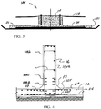
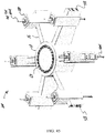
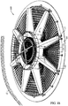
- the present invention pertains to a fatigue resistant foundation for wind towers which comprises a plurality of components, namely a central vertical pedestal, a substantially horizontal continuous bottom support slab with a stiffened perimeter, a plurality of radial reinforcing ribs extending radially outwardly from the pedestal and a three-dimensional network of vertical, horizontal, diagonal, radial and circumferential post-tensioning elements embedded in the footing that keeps all the structural elements under heavy multi-axial post compression, which reduces stress amplitudes and deflections and allows the foundation to have a desirable combination of high stiffness and superior fatigue resistant while improving heat dissipation conditions during construction by having a small ratio of concrete mass to surface area thus eliminating the risk of thermal cracking due to heat of hydration.
- any tower or column can be used on the foundation including but not limited to, antennas, chimneys, stacks, distillation columns, water towers, electric power lines, bridges, buildings, or any other structure using a column.
- a wind turbine foundation has a plurality of components, namely a central vertical pedestal, a substantially horizontal bottom support slab, and a plurality of radial reinforcing ribs extending radially outwardly from the pedestal, the ribs are prefabricated and transported to job site, but the pedestal and support slab are poured in situ at the site out of concrete.
- the prefabricated ribs 16 are equipped with load transfer mechanisms, for shear force and bending moment, along the conjunctions with the cast in situ support slab, pedestal and perimeter beams.
- the prefabricated ribs are also equipped at their inner ends with load transfer mechanisms, for shear force and bending moment, along the conjunctions with the cast in situ pedestal.
- the ribs are arranged in a circumferentially spaced manner around the outer diameter of the pedestal cage assembly before or after slab reinforcing steel is installed. Forms are then arranged for the pedestal and support slab.
- the support slab is cast in situ by pouring concrete into the forms and then pedestal concrete is poured into the pedestal form over the slab. When the concrete cures the support slab is united to the prefabricated ribs 16 and the ribs 16 are also united to the pedestal.
- the final result is a continuous monolithic polygon or circular shaped foundation wherein loads are carried across the structure vertically and laterally through a continuous structure by the doweled and spliced reinforcing steel bars which are integrally cast into the pedestal, ribs and support slab.
- the combination of the high stiffness of the ribs 16, solid pedestal and continuous slab construction across the pedestal, and through or under ribs 16, allows the slab to behave structurally as a continuous slab over multiple rigid supports resulting in small bending and shear stresses in the slab, reducing deflections and increasing the stiffness of the foundation, improving fatigue conditions as well as allowing for the benefits of an economical design.
- Support slab reinforcing steel covers the entire footprint of the foundation and extends, without interruption, across the slab area and into the pedestal to improve the structural performance of the foundation under different loading conditions.
- Perimeter beams or thickened slab edges around the perimeter add stiffness and strength to the foundation and provide the benefits of a two-way slab system. Circumferential post-tensioning of the slab edge is used to increase the structural capacity of the ribs and the pedestal by creating eccentric post-compression in the ribs and by reducing stress amplitudes in the slab, ribs 16 and pedestal.
- the foundation of the present invention substantially reduces the amount of concrete used in a wind turbine foundations of spread footing style, simplifies the placement of rebar and concrete in the foundation, allows for labor and time savings and shortens the foundation construction schedule when compared to conventional foundation designs.
- This invention provides the wind energy industry with a foundation system suitable for utility scale wind turbines including 1.5 MW through 10 MW or larger turbines, wherein the amount of cast in situ concrete work is limited, and the number of concrete trucks required for the foundation is kept to a smaller and more manageable level, and the amount of rebar used in the foundation is around 60% less than conventional footings.
- the present invention uses prefabricated components that meet size and weight limits for standard ground freight shipping on typical roads and highways, without resorting to special permitting for oversize or overweight shipments, keeping in mind that the foundation width for large turbines can easily exceed sixty feet.
- One embodiment of the invention uses specific combinations of precast components with cast in situ components designed to speed up construction without compromising the rigidity and structural continuity and optimization of the foundation.
- the combination of high strength, high stiffness prefabricated ribs, solid pedestal construction and continuous slab construction across the pedestal, and through or under the ribs, allows the slab to behave structurally as a continuous slab under multiple rigid supports resulting in small bending and shear stresses in the slab, reducing deflections and increasing the stiffness of the foundation, substantially reducing fatigue as well as allowing for the benefits of rapid construction and economical design.
- the present invention improves the geometry of the foundation in order to enhance dissipation conditions for the heat of hydration due to the typical temperature rise after casting.
- This design feature is achieved by reducing the thickness of the support slab and the ratio of concrete mass to surface area, thus reducing the risk of thermal cracking and protecting the structural integrity of the foundations.
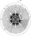
- the present invention optimizes the design support slab by configuring slab reinforcing to span between supporting ribs, - and allowing it to continue under or across the ribs.
- Each slab panel - may be triangular or pie-shaped and is prestressed along all three sides such that a multi-axial prestress is generated in each slab panel.
- Slab panels with radial and perimeter post tensioning elements form a robust horizontal trussed diaphragm and as a result, the required slab thickness is optimized and the amount of cast in situ concrete is reduced.
- the present invention reduces the maximum rebar length for field installation to approximately half the conventional length, to roughly 7.6 meters (twenty five feet), which is significantly shorter when compared to conventional footing that may requires 15.2 to 18.3 meters (fifty to sixty foot) long reinforcing bars.
- the present invention allows rib dowels, or post tensioning tendons, extending inwardly into the pedestal at one end, to continue without interruption between distal ends of the foundation. As a result each pair of ribs 16 on opposite ends of the pedestal will behave structurally as one continuous beam across the width of the foundation.
- the present invention reduces fatigue for concrete and rebar in the foundation by minimizing stress concentrations through appropriately configured connections and component geometry.
- the solid and deep construction of the pedestal allows for great reduction of stresses across the pedestal and at the conjunctions between the pedestal and the surrounding slab and ribs. Dowels from the ribs into the pedestal are relatively deep to reduce stresses in the surface zone of the pedestal and can be paired with corresponding dowels extending from the opposite end of the foundation.
- the solid pedestal offers generous bearing conditions for the tower base plate and improves the geometry as needed to minimize fatigue.
- the present invention employs prestressing and/or post tensioning techniques in order to maximize the performance of the foundation, and to extend its life span. Besides the vertical tensioning of anchor bolts, tensioning of horizontal and diagonal tendons are employed along the length of the concrete ribs and across the pedestal. Further, perimeter and radial post tensioning elements embedded in the slab are employed. Post-tensioning of the ribs is designed in an eccentric manner to counter balance and reduce the stresses from the dead loads on the foundation. This can be accomplished by setting an eccentric post tensioning load pattern in the ribs with higher axial force at the bottom than at the top of the rib. The circumferential post tensioning load in the slab provides additional desirable eccentric prestressing of the ribs and the pedestal and helps increase rib load capacity and rib fatigue resistance.
- An object of this invention is to provide the wind energy industry with a low construction time, reliable, and cost effective foundation system suitable for most wind energy projects, including projects using the largest utility scale turbines and tallest towers, while providing a foundation lifespan that is longer than conventional foundation systems.
- Another object of this invention is to reduce the cost of wind energy projects by realizing savings in the areas of reducing concrete and rebar quantity, reducing concrete trucking service, decreasing concrete pouring and finishing, improving logistics, and reducing man-hours and crane operations.
- Another object of this invention is to improve dissipation conditions for the heat of hydration and the typical temperature rise after casting. This goal is achieved by reducing the ratio of concrete mass to surface area. When concrete is cast in massive sections for wind tower foundations, temperatures can reach high levels and the risk of thermal cracking becomes very high unless cooling techniques or special admixtures are applied. Thermal cracking often compromises the structural integrity of the foundations.
- a further object of one embodiment of this invention is to improve foundation structural properties due to fabrication of some structural components in a fully controlled environment of a precast concrete plant or a suitable facility at or near the project site and to utilize and benefit from advancement in concrete construction in areas such as concrete admixtures, special cements and fiber reinforcement.
- Still another object of this invention is to utilize desirable features and benefits associated with mass production of precast concrete such as high reliability and uniform consistency and high compressive strength.
- Another important object of this invention is to minimize chances for errors in bar placement, spacing and layout by providing pre-marked spacing for splicing slab rebar with existing dowels extending from ribs.
- a further object of this invention is to use light weight, small diameter, short and easy to handle rebar for the cast in situ concrete.
- a further object of this invention is to provide the wind energy industry with a solution for all weather foundation construction.
- Still another object of this invention is to improve safety and accessibility around foundations under construction, and reduce hazardous conditions for construction crews.
- a further object of this invention is to increase productivity and increase the number of footings that can be built in a given time frame using the same number of workers, when compared to conventional foundation designs built under similar conditions.
- Another object of this invention is to employ prestressing and/or post tensioning techniques in order to maximize the performance of the foundation, improve its fatigue resistance and extend its life span.
- Another object of this invention is to provide the wind energy industry with reliable and readily available designs, and optionally, prefabricated components, for every wind energy project, wherein foundation designs are pre-approved by and coordinated with turbine manufactures and certification agencies.
- a further object of this invention is to use standard designs to reduce engineering work and simplify the permitting process, as well as improve the project construction schedule.
- Still another object of this invention is to speed-up construction by using many prefabricated components including rebar meshes and cages, bolt cage assemblies, pre cut post-tensioning strands, preassembled post-tensioning bundles, pre-cut post-tensioning duct sections and prefabricated concrete forms and optionally, precast ribs.
- It is also the object of this invention is to provide wind energy developers with the ability to select pre-approved complete foundation designs for wind turbine foundation based on project and site variables including turbine model and tower height; site geotechnical characteristics; and desired foundation styles such as gravity, anchored or piling support foundations.
- Another object of this invention is to provide foundation contractors with the convenience and economy of using commercially available prefabricated components with complete assembly and detail drawings that can be delivered to any project site with short lead times.
- a further object of this invention is to improve the quality and productivity of foundation construction due to experience gained from practicing standard construction techniques with repetitive production steps.
- Still another object of his invention is to produce foundation designs suitable for shallow and deep offshore installations.
- Another object of this invention is to use the modular foundation system for other tower structures such as chimneys, stacks, distillation columns, telecommunication towers, and water towers.
- Yet another object of the invention is to improve tower base bearing resistance in concrete pedestals supporting wind towers such that it becomes possible to build the pedestal and the foundation with concrete having the same compressive strength without increasing the diameter of the pedestal.
- Another object of the invention is to build wind tower foundations in one continuous concrete pour.
- Another object of the invention is to independently produce prefabricated components for offshore foundations to be assembled on a barge without having the critical path of completing a first component before a second component can be constructed.
- the present invention pertains to a wind turbine foundation for wind turbines.
- the foundation comprises a plurality of components, namely a central vertical pedestal, a substantially horizontal bottom support slab, and a plurality of radial reinforcing ribs extending radially outwardly from the pedestal.
- the ribs may be prefabricated and transported to job site, but the pedestal and support slab are poured in situ at the site out of concrete. Alternatively the ribs may be cast in situ.
- the present invention pertains to a fatigue resistant foundation 100 for wind towers which comprises a plurality of components, namely a central vertical pedestal, a substantially horizontal continuous bottom support slab with a stiffened perimeter, a plurality of radial reinforcing ribs extending radially outwardly from the pedestal and a three-dimensional network 500 of vertical, horizontal, diagonal, radial and circumferential post-tensioning elements embedded in the footing that keeps all the structural elements under heavy multi-axial post compression, reduces stress amplitudes and deflections and allows the foundation 100 to have a desirable combination of high stiffness and superior fatigue resistance while improving heat dissipation conditions during construction by having a small ratio of concrete mass to surface area thus eliminating the risk of thermal cracking due to the heat of hydration.
- a construction site is prepared by excavation, flattening and preparation of soil for the foundation 100.
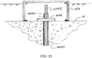
- the foundation 100 may be set on pilings, on piers, or have anchors (soil anchors or rock anchors 404 or micro-piles 401 or other types) in a conventional manner.
- the present invention ensures good contact between foundation 100 and soil, or sub-base 14a, by casting.
- the foundation 100 is cast against prepared soil, a crushed stone sub-base 14a, a mud slab or a membrane sheet in case of offshore foundations assembled on a barge or in dry docks.
- Known grouting and leveling techniques under precast elements can be employed for ensuring plumb installation and good soil contact.
- the foundation 100 may be set on a mud slab 14 or on compacted granular fill.
- the mud slab 14 is often a thin plain concrete layer intended to provide a clean and level base for the foundation installation.
- a plurality of three or more precast stiffener ribs 16 are placed on the mud slab 14 or compacted granular fill inside of the excavation pit 12.
- the precast concrete stiffener ribs 16 may have means for leveling or other leveling techniques can be employed for level and plumb installation. If desired, grouting techniques can be used to ensure complete rib base contact with the mud slab 14 or sub-base.
- the precast concrete ribs 16 may have bases 21 with left shear key 38 and/or shear connectors and right shear key 36 and/or shear connectors.
- the precast concrete stiffener ribs 16 may also have a vertical shear key 34.
- the shear keys 34, 36 and 38 and associated dowels 40, 42 and 46 are to ensure continuous connections, with complete transfer of shear and bending loads, between the precast concrete rib stiffener 16 and the cast in place concrete which is to be poured into the foundation 100 to form the bottom support slab 20.
- the precast concrete stiffener ribs 16 have upper dowels 40 and lower dowels 42 extending on the right and left sides of the base 21 which interconnect with and spliced to upper mesh rebar 22 and lower mesh rebar 24 installed between the ribs 16 and connected to dowels 40, 42 to form reinforcement for the slab 20 and pedestal 10 of foundation 100 when the concrete is poured.
- the base 21 of rib 16 and the top of rib 16 also have dowels 46 radially entering the pedestal 10 in the center of the foundation 100.
- Doweling of rebar between the ribs 16 and foundation components can be achieved with rebar dowels extending from the prefabricated elements or by using rebar couplers, bar extenders or any mechanical rebar splicing system.
- Arrays of grout or epoxy filled sleeves 42b arranged in the slab 20 could receive corresponding arrays of vertical dowels 42a extending from the bottom of prefabricated ribs 16 or perimeter beams 190 or other prefabricated components.
- Shear keys, or shear transfer mechanisms can be replaced with, or combined with, corbels or shear studs, or other shear connectors such as angled rebar or embedded steel shapes 34a.
- an array of steel beams 16s are encased into the web of the rib 16 and extend inwardly into the pedestal cavity at the inner most end of ribs, and serve as a suitable shear force transfer mechanism between the rib 16 and the pedestal 10.
- the foundation 100 comprises a steel frame 16f fully encased in concrete and has a central tower receiving a metal cylinder 56b fixed to an array of radially extending steel girders 16s encased in concrete beams 16, 21, 190 and rigidly connected at their outer ends to an array of perimeter beams 190 encased in the concrete foundation 100 and a reinforced concrete slab-on-grade 20 covering the foot print of the foundation 100 and connected to the said steel frame.
- the ribs 16 may be treated with concrete bonding agent along surfaces where cast in place concrete is received.
- foundation 100 may be provided with drains around the perimeter and the top surface of the slab 20 is slightly sloped towards the drains such that water is drained away from foundation 100.
- the slab when foundations are installed in sites prone to seismic activities and elevated water table, the slab may have holes to prevent soil liquefaction during seismic events.
- the ribs or other foundation elements may be covered or coated with protective material for extending the life span of the footing.
- the ribs 16 are placed on the mud slab 14 first and then the pedestal cage 50 made of an array of rebar, preferably Z or C shaped rebar and circumferential rebar is assembled around anchor bolt assembly 60 Alternatively the pedestal cage 50 is assembled first or a preassembled pedestal cage 50 dropped into place first and then the ribs 16 with dowels 46 are slid into place so that dowels 46 and shear connectors 34, 34a fit between the elements of pedestal cage 50 rebar assembly.
- the precast concrete stiffener rib 16 has lifting lugs 32 to help place the stiffener rib 16 into the excavated construction area.
- the base 21 has a flat bottom surface such that the ribs may stand on their own on the mud slab 14 or compacted granular fill or during transportation from precast plant to foundation site.
- the precast concrete stiffener ribs 16 have prestressing elements 58 running through the ribs 16 radially from the outside of the ribs 16 and through pedestal 10.
- the radial prestressing elements 58 may be anchored to the opposite side of the pedestal or optionally run through the opposing precast concrete stiffener 16 on the other side of the pedestal 16 and anchored at the end of the opposite rib 16.
- the dowels 46 extending radially inward from ribs 16 may be connected to, or spliced with, corresponding dowels arranged in the pedestal cage 50.
- additional rebar dowels 48 which will facilitate the continuity of the structural components through the pedestal 10 as well as resist bearing, shear and bending loads.
- a bolt assembly 60 comprising a bolt template 52 an embedment ring 54 and anchor bolts 56 protected by a PVC sleeve 57 or wrapped with a material to prevent bonding between the anchor bolts 56 and concrete to be poured.
- the anchor bolts 56 have a top portion which is used to attach the base flange 301a of a tower or column to the pedestal 10.
- a grout trough template 52 at the bottom of the bolt template 52 may be used to create a grout trough 90 to ensure a good connection of the tower or column to the pedestal 10.
- the grout trough 90 will be formed by removing the bolt template 52 from the anchor bolts 56 after the concrete has been poured.
- Radial dowels, prestressing elements or shear connectors at the inner end 16c of ribs 16 should be spaced to clear anchor bolts 56 and other reinforcement arranged in pedestal cage 50.
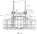
- slab forms 17 may sit directly on the mud slab and rib forms 16b are supported and kept elevated above slab 20 elevation by means of adjustable and reusable support legs arranged in the rib forms 16b. Small footings or thickened mud slab areas could be used under rib form support legs. Pedestal forms 102 can be supported by rib forms 16b or by separate support legs.
- the alignment apparatus 130 has a central post 132 with arms 134 attached perpendicularly to the center post and having legs 136 for attachment to the top of the ribs 16 to provide added stability, and bolt circle proper alignment during construction.
- the legs 136 have an adjustable height relative to the arms 134.
- the arms 134 may have braces 138 attached to the central post 132 for holding the arms 134 straight.
- the central post 132 may also have rod supports 135 for holding reinforcement rebar such as reinforcement rebar 80 which are spliced to dowels 46.
- the alignment apparatus 130 also has adjustable support members 140 for attachment between the arms 134 and the bolt template 52 to align the anchor bolts 56 so they are upright.
- the alignment apparatus 130 can support the bolt assembly 60 without the central post 132 by relying on the legs 136 supported by ribs 16, which allows the lower portion of the central post 132 to be removed if desired.
- Alignment apparatus 130 can be used as a template to ensure proper location, elevation and orientation of ribs 16.
- the ribs 16 can be of any shape or size depending on the specifications of the tower and loads thereon.
- the ribs 16 may be trapezoidal, rectangular, T shaped or I beam shaped.
- the ribs 16 may have intermediate stiffener plates or diaphragms for improved structural performance.
- the ribs 16 or rib forms 16b may receive ramps or catwalks thereon for easy access to the forms during construction.
- Ribs 16, or rib forms 16b may have means for receiving and supporting perimeter forms 18, such as bolts or threaded inserts for receiving and supporting the pedestal forms 102.
- the ribs 16, or rib forms 16b may also have attachment means 15 for holding base forms 17.
- the pedestal forms 102 may be equipped with platform sections for allowing access around the pedestal and the rest of the footing.
- concrete forms may be attached such that concrete can be poured to form the pedestal 10 and base 20 of the foundation 100.
- Pedestal forms 102 may attach to the ribs 16, or rib forms 16b, by bolts 18 or by any other means.
- the base perimeter forms 17 may be attached to the ribs 16, or rib forms 16b, by bolts 15 or by any other means.
- the base perimeter forms 17 may be supported to the ground or the mud slab.
- the prefabricated components are be fitted with ducts and anchor hardware according to design specifications.
- the cast in place components will be fitted with matching ducts to facilitate the continuity of tendons across the foundation 100.
- duct grouting is carried out as required. If the un-bonded, bundled mono-strand system is employed, no duct or grouting is required.
- Circumferential post tensioning 59 creates a desirable symmetric bi-axial post compression in the slab 20.
- Circumferential post tensioning 59 is applied at an elevation well below the neutral axes of the ribs 16 thus creating eccentric post compression in the ribs 16 and the pedestal 10 and resulting in increased nominal moment and shear capacity of the ribs 16 as well as improvement in multi-axial fatigue resistant of the pedestal 10, ribs 16 and the slab 20.
- Radial or diametric post tensioning elements 58 extend from rib 16 to opposite rib 16 across the pedestal 10.
- Radial post-tensioning is applied with an eccentric load pattern, with higher post compression below the neutral axis of the rib.
- the foundation 100 is kept under heavy multi-axial eccentric post compression stress, thus increasing rib structural capacity to resist soil support reaction and providing low deflections, high stiffness and low stress amplitudes resulting in high fatigue resistance and high durability of the slab.
- Backfill is added over the slab 20 for increased stability and stiffness of the foundation 100.
- the bolt assembly 60 can be replaced by a tower section 56b embedded in pedestal 10 concrete.
- the embedded section 56b having means 56c for receiving a tower base 301 by means of a bolted connection arranged at the top of the section 56b
- the embedded metal cylindrical tower section 56b encased in pedestal 10 concrete is provided with holes for rebar and post tensioning tendons 58 to extend through the metal cylinder.
- Post tensioning 58 tendons can extend through holes arranged in the cylinder and across the pedestal 10, through the ribs 16 to be anchored on distal ends of the foundation.
- Pedestal 10 can be any size or shape, round, triangular, square, polygon or other shape depending on the specifications of the tower and loads thereon.
- the ribs 16 can be in any pattern around the pedestal 10.
- the foundation 100 may have a square pedestal 10 and ribs 16 at the corners parallel to the faces of the pedestal.
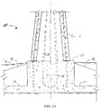
- the pedestal 10 may have a stepped construction with an enlarged lower cross section to reduce the length of the cantilevered ribs 16.
- Pre-assembled reinforcement sections (meshes) of the slab 20 components can be lowered into place in the slab 20 to speedup construction. All rebar dowel or metal shear connectors extending through construction joints may be galvanized or Epoxy coated to prevent corrosion.
- the use of mechanical couplers in the foundation 100 may be limited or avoided. Specified mechanical couplers must be tested and certified for the number of load cycles in the life span of the foundation 100.
- the ribs are cast in place in reusable rib forms 16b.
- the ribs 16 are cast in place jointly with the pedestal 10 in one continuous pour over the slab.
- the ribs 16, the pedestal 10 and the slab 20 are all jointly cast in one pour. All rib internal components including rebar assembly with dowels and prestressing elements are placed inside the forms then cast in place concrete is poured into the rib forms 16b as well as into pedestal 10 and slab 20 forms.
- Rib reinforcing cages 16rc can be assembled above grade and lowered into the foundation in one or more sections.
- rib forms 16b with internal rib reinforcing cages 16rc are preassembled and lowered into the foundation by cranes to mesh with slab reinforcing sections 22, 24 already placed in the foundation.
- the radial reinforcing pattern 22 of the slab 20 enables the meshing rib dowels 42 between slab reinforcing 22, 24 without geometric interference.
- Ribs 16 can also be made in segments 16sg and eventually united by means of doweling or by using segmented post-tensioned construction techniques. Rib anchor zone 16x with anchor trumpets 16t and hardware can be prefabricated separately of higher strength concrete than the rest of the rib 16.
- prefabricated perimeter beams 190 with post tension ducts may serve as perimeter forms and become part of the structure.
- An array of precast, rectangular or L-shaped beams with means for connecting to the slab 20 and the ribs 16 can be used foundation perimeter construction.
- the perimeter (edge) beams 190 can rest directly on the mud slab and connect to the slab 20 using horizontal dowels and shear keys arranged on the inner side.
- the perimeter beam 190 is elevated and connects to the top of the slab 20 using dowels 190b extending from the bottom of the perimeter beams 190
- the precast perimeter beams 190 may have dowels 190b and shear keys 192 (such as corrugations) extending from their sides ends for connecting to the ribs 16.
- the ribs 16 will have corresponding dowels 190b and shear keys 192 for receiving and supporting perimeter beams 190.
- the connection between ribs 16 and perimeter beams 190 is established using closure pours in small cavities at the conjunctions of the ribs 16 and the perimeter beams 190.
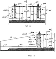
- the foundation 100 pertains to a hybrid gravity based and rock anchored foundation.
- Ribs 16 can be made with arrangement, mechanisms and connecters for receiving piles 400 or micro-piles 401or anchors 404 in different configurations.
- Vertical through holes 16g in the ribs 16 can provide means for receiving a pile 400, micro pile 401 or an anchor 404.
- Bearing elements 404b and grouting are arranged on top of each rib 16 to establish the required structural connection.
- An array of bearing plates 404b with tensioning nuts 404c on each soil/rock anchor may be used to compress the foundation 100 against supporting soil.
- Vertical through holes 16g with corrugations 16f for the anchor 404 extend through the foundation 100.
- Bearing plates 404b with tensioning nuts 404c can be placed on top of the pedestal 10 or in the foundation 100. If desired ribs 16 may have piers 180 extending vertically from the ribs 16 and the top of the pier elevation is raised to a higher elevation to make anchor bolts accessible for tensioning and testing. Typical rock or soil anchor construction and grouting methods can be utilized. Another option is to house rock anchor bolts and bearing plates 404b and tensioning nuts 404c in accessible corrosion protection compartments above the foundation 100.
- the invention pertains to a foundation 100 that comprises the following elements:
- the prefabricated components can be molded at a facility under controlled conditions for good quality concrete setting and controlled rebar spacing which is superior to what can be obtained on a job site and at a lower cost.
- the ribs 16, acting as deep stiff horizontal cantilever support, allow the base of the foundation slabs to have a relatively small thickness using less cast in place concrete and rebar thus lowering the cost for each foundation.
- ribs 16 may have reusable temporary supports 16y, or other means, arranged at the ribs 16 to hold the ribs 16 in place, maintain them plumb during construction and elevate them at a predetermined height over slab reinforcing 22,24.
- This style of ribs 16 is intended to be raised above the ground or mud slab 14 so that the foundation support slab 20 can be poured in place continuously under ribs 16.
- Dowels 42 and shear connectors for this style may be arranged at the bottom of the rib 16 for connecting with base slab 20 which extends under the raised rib 16.
- the rib inner ends 16c will be partially encased in the pedestal 10 to increase rib torsional end resistance.
- the final result is a continuous monolithic foundation wherein loads are carried across the structure vertically and laterally through the continuous structure by the doweled and spliced reinforcing steel bars which are integrally cast into the pedestal 10, ribs 16 and support slab 20.
- the combination of the high stiffness of the ribs 16, solid pedestal 10 and continuous slab 20 construction across the pedestal 10, and under ribs 16, allows the slab 20 to behave structurally as a continuous slab 20 over multiple rigid supports resulting in small flexural and shear stresses in the slab 20, reducing deflections, improving fatigue conditions and increasing the stiffness of the foundation as well as allowing for the benefits of an economical design.
- Cast in situ concrete can be shielded from extreme weather, including heat, cold, rain and snow, by simply extending blankets, covers or shields between ribs 16 during construction, and then using heaters or fans as required to regulate temperature, humidity of concrete to allow for proper setting and curing conditions.
- Another embodiment of the present invention pertains to a leveling technique that simplifies the tower base leveling process and shortens the number of steps required for grouting under a tower base.
- the bolt template 52 is provided at the very top of the bolt assembly 60 with at least three sets of additional bolts 53 and corresponding threaded bolt inserts 53b suitable for embedment in the concrete.
- Such leveling bolts 53 and inserts 53b will be located outside or inside the bolt circle 60a of tower base, but directly under tower base flange 301a. This allows for continuity of grout bed 90a construction and provides an easy access to leveling bolts 53. Small cutouts at leveling bolt locations may be used.
- Another benefit of this leveling technique is having the ability to apply continuous grout bed 90a that is free of cold joints, under the tower base flange 301a in one session as well as having the ability to tension all anchor bolts 56 in one work session.
- the onshore foundation may have a pedestal 10 that is rigidly connected to vertical concrete stem 11 that is fixed to a tower base of a wind tower.
- the pedestal and the stem are vertically prestressed with vertical post tensioning elements extending through the height of the foundation.
- the stem is fitted with an array of bolts 60 for receiving and supporting the tower base 301.
- the foundation design can be reconfigured to support lattice towers 200 comprising multiple columns connections to foundations in a spaced array.
- the ribs 16 will be provided with column receiving components including embedded anchor bolts (or grouting around embedded element) and an integrated pier design into the rib.
- the rib geometry may be widened and enlarged at the integral pier 180
- the array of said integrated piers ribs 16 are fitted with means for receiving and supporting the legs or the columns 200a of the lattice tower 200.
- the integrated piers can extend above final grade elevation, while the top of pedestal 10 may stay below final grade elevation. For this foundation style, pedestal elevation may be depressed and tower receiving components may not be required in the pedestal 10.
- This configuration may also be used in offshore applications wherein a prefabricated gravity foundation 100 is connected to lattice tower structure 200 that is fitted with a wind tower receiving component at its top.
- the foundation 100 will be installed over prepared seabed and filled with a suitable backfilling material 13, and surrounded with scour protection 13b.
- the foundation 100 may be supported on an array of concrete piers deeply embedded and frozen into the ground.
- Anchor bolts 404a can be used to secure the ribs 16 to their supporting piers 402 around the perimeter of the foundation 100p.
- the invention pertains to a fatigue resistant gravity based spread footing for use under heavy multi-axial cyclical loading of a wind tower 300 which comprises a plurality of components, namely a central vertical pedestal 10, a substantially horizontal continuous bottom support slab 20 with stiffened perimeter, a plurality of radial reinforcing ribs 16 extending radially outwardly from the pedestal 10 and a three-dimensional network of vertical 60, horizontal 110, 111, 112, 58, diagonal 58b, 58c, radial 58 (or diametric) and circumferential 59 post-tensioning elements that keep the structural elements under heavy multi-axial post compression with specific eccentricities and orientations that are intended to reduces stress amplitudes and deflections and allows the foundation 100 to have a desirable combination of high stiffness and superior fatigue resistance while improving heat dissipation conditions during construction by having a small ratio of concrete mass to surface area thus eliminating the risk of thermal cracking due to heat of hydration.
- a wind tower 300 which comprises a plurality of components,
- a pedestal 10 may have an array of vertical post tensioning elements 56 that does not connect to a tower 300, and an embedded tower section 56b bolted to a tower structure 300.
- Radial post-tensioning 58, extending across the foundation 100, in pairs of ribs 16, allows for the desirable structural continuity and the direct transfer of loads from a downwind ribs 16 into the pedestal 10 and then into the opposing upwind ribs 16.
- Radial and circumferential post compression stresses in the slab 20 and/or perimeter beams 190 allows for a desirable reduction in stress amplitudes the structural continuity between slab 20 spans and/or perimeter beam 190 spans, across the ribs 16, thus creating a desirable load sharing mechanism between adjacent ribs 16 by forcing more ribs 16 to be engaged in resisting tower loads.
- the invention pertains to a durable, high-stiffness, fatigue-resistant foundation structure 100 for onshore wind tower installations which comprises:
- All components are made of high strength reinforced concrete and are rigidly connected to each other to behave as a monolithic spread foundation structure.
- the structural components are rigidly connected with arrays of rebar dowels (passive reinforcing) and /or post-tensioning elements extending through the conjunctions.
- the slab 20 functions as a two-way slab system that is free of construction joints across the footprint of the foundation and spans continuously over multiple ribs 16. Perimeter post tensioning 59a or circumferential post tensioning 59 of the slab 20 is applied at an elevation well below the neutral axes 16n of the ribs 16 to cause eccentric loading of the ribs 16 and the pedestal 10.
- Radial post-tensioning elements with an eccentric load pattern extend from rib end to opposite rib across the pedestal 10, or to the opposite end of the pedestal 10.
- the foundation 100 is kept under heavy multi-axial eccentric post compression stress, thus increasing rib structural capacity to resist soil support reaction and providing low deflections, high stiffness and low stress amplitudes resulting in high fatigue resistant and high durability.
- Backfill 13 is added over the slab 20 for increased stability and stiffness of the foundation 100.
- Soil support reaction under the slab 20 is transferred from the slab 20 to the ribs 16 and thickened slab edge 21 (or perimeter beams 190) as in two-way slab systems with more load distribution going to the ribs 16 in the primary span.
- Perimeter 112 or circumferential 59 post-tensioning is applied, generally in the orientation of the primary span that effectively reduces stress amplitudes and deflections in the slab 20 by keeping the slab 20 under heavy post-compression in the directions of primary slab spans 20s1, and secondary slab span 20s2 around the foundation.
- the size, distribution, eccentricity and location of post tensioning elements 58 in the ribs 16 and the slab 20 are used to dictate the natural frequencies of the foundation 100 to be in a safe range relative to operating frequencies of the wind generator according to turbine manufacturer recommendations.
- the said 3-dimensional post-tensioning network 500 in the foundation keep all the structural components (Pedestal 10, ribs 16, slab 20, thickened slab edges 21 (or integral edge beams)) under multi-axial post compression confinement resulting in lower stress range amplitudes thus yielding higher stiffness, more effective crack control, lower deflections and improved fatigue resistance. Superior fatigue resistance and long life- span are achieved by keeping most of the structural elements of the foundation 100 under multi-axial compression while resisting operating loads or even during normal and abnormal extreme loads from the supported structure (wind power generator).
- rib post-tensioning requirements are reduced by engaging fully developed bar dowels from the rib into the pedestal connection as well as extending fully developed radial rebar dowels of the slab 20 into the pedestal 10, thus allowing passive reinforcing to participate in the said connection especially under extreme loads.
- a radial slab reinforcing pattern with tapered rib width was is very cost effective as the rib to pedestal connection benefits from a large number of top and bottom radial slab reinforcing bars participating in the said connection, as the rib width widens, thus reducing the number of bottom post-tensioning strands required for the said connection.
- the structural configuration of the foundation 100 reduces the overall cumulative deflections in the structure under tower loads and significantly improves the rotational stiffness of the foundation 100 which is a key factor in determining the size of foundations in wind turbine installations.
- the rotational stiffness is also improved by the interlocking between surrounding soil (after backfilling) and the multiple surfaces and vertical faces of the foundation structure.
- the horizontal stiffness is improved by the passive earth pressure on the multiple surfaces of the structure. Both rotational and horizontal stiffness achieved by this design are much higher than conventional tapered inverted-T gravity spread footings especially for onshore foundations installed below grade in an excavated pit because of the increased interlocking surface area and increased passive earth pressure and increased friction on the multiple faces of the fatigue resistant foundation 100.
- the solid-core pedestal 10 comprises a continuous reinforcing cage 50 and a tower receiving component 56, such as anchor-bolt assembly 60, with a cylindrical array of bond protected high strength post-tensioning bolts 56, for connecting to wind tower base flange 301a.
- the tower receiving component may comprise an embedded cylindrical metal tower section 56b with means 56c for connecting to a tower section such as a flange 56c with bolt holes 56d for receiving bolts 301b at its top and with an array of holes 56h to allow the passing of rebar 46 and post tension tendons 58.
- the embedded tower section 56b is also fitted with conventional bearing flanges 56e and ring stiffeners for interlocking with pedestal concrete.
- the anchor bolt assembly ensures structural continuity between the tower 300 and the pedestal 10.
- the post-tensioning forces of the anchor bolts 56 are selected to insure that the tower base flange 301a remains in contact with the pedestal 10 under extreme normal and abnormal load conditions.
- the bolt assembly 60 includes, at its bottom end, a bearing element 54 that may consist of an embedment ring plate 54 that is made of segments that are welded together.
- radial post-tension tendons 58 and rebar reinforcing elements 46 extending from the ribs 16 and the slab 20 pass through the pedestal reinforcing cage 50, or through holes 56h in the embedded metal tower section 56b.
- post-tensioning elements 58, 110, 111 are flared horizontally, profiled vertically, arranged in matrix groups, spaced and draped in a manner that allows for optimum utilization of post-tensioning and ease of installation while avoiding tendon congestion and stress concentrations as tendons 58,110, 111 crisscross in the pedestal 10.
- the regrouping of tendons to form flat and wide matrix along each axis was found to be effective in avoiding tendon congestion especially in the pedestal 10.
- the said flat and wide matrix of tendons is placed as high or as low as possible to maximize their moment arms and optimize their contributed moment capacity.
- bonded (multi-strand and grouted) or un-bonded encapsulated (mono-strand) post-tensioning elements and their associated construction techniques can be used in the foundation 100.
- the rib's thickness 16th can be gradually increased at the connection to the pedestal 10 to increase rib flexural, shear and torsional capacity and enhance pedestal confinement 16m.
- the post-tensioning requirements can be reduced by engaging dowels 46 at rib-to-pedestal connection and by extending fully developed radial dowels 46, 22r, 24r from the rib 16 and the slab 20 deep into the pedestal, thus allowing passive reinforcing to participate in the connection.
- ribs 16 top surface can be tapered to a substantial slope extending vertically to an elevation near the top of pedestal allowing the ribs 16 to benefit from diaphragm action at their inner zone and also provide lateral support for the full height of the pedestal 10 and to provide concrete confinement at the highly stressed zone at the top of pedestal under tower base flange 301.
- the foundation may have a circular or polygonal foot print.
- the thickened slab edge 21 21 (or perimeter beam) may extend above or below the foundation.
- a shallow perimeter beam profile should be selected for ease of backfilling and improved accessibility for roller compactors during the backfilling of the foundation 100.
- a thickened slab ring beam 21 may be designed to be at an offset distance away from the slab edge allowing the slab segment, outside the ring, to behave as a cantilever. This configuration reduces slab span and deflections as well as the volume of concrete required in the foundation 100.
- the configuration of the slab 20 and its continuous reinforcing including that of the thickened slab is configured to create a rigid composite connection to the ribs 16 with high stiffness which is sufficient to allow adjoining ribs 16 to participate more in resisting the loads and thus reducing local deflections and increasing overall foundation stiffness in addition to reducing the unsupported length of cantilever radial ribs 16.
- the pairing of the ribs 16 on distal ends 10x and the continuous perimeter beam construction yield a cost effective layout of post-tensioning that uses a small number of tendons and corresponding anchors as well as reduces friction losses by avoiding sharp turns in tendon layout.
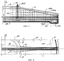
- the tendons of the ribs 16 are anchored in a matrix array 58m at the outer end of the rib and extend horizontally and diagonally along the rib to split into at least two groups 58a and 58b one near the bottom and the other near the top of the rib as it connects to the pedestal 10.
- the tendons are more concentrated at the bottom than at the top in a concentric prestrssing pattern 58m1 that is intended to maximize the structural capacity of the foundation and meet the flexure and shear demand of the governing load cases.
- Ribs 16 may have thickened flanges, at their connection to the pedestal 10 that may also house post tensioning anchors for tendons 58 extending from ribs 16 on the opposite side of pedestal.
- the ribs 16 may also have post tensioning anchors along their sides or tops if tendon curtailment methods are applied in the design.
- the ribs 16 may also have embedded loop anchors if looping of tendons is used in the design. Loop anchors 70 could also be used in the pedestal 10 to support and vertically prestress precast concrete towers 300b, or concrete stems 11.
- the tendons 58 in ribs 16 extend horizontally and diagonally to be split into three distinctive groups as they enter the pedestal.
- the first group 58a with more tendons is placed at the bottom of ribs 16 or in the slab to create camber for reducing deflections and improving foundation soil contact as well as meet the high flexural demand from the governing load cases, and the second group 58b slope up diagonally to follow the geometry of the top of the rib as they enter the pedestal 10.
- the third group 58c is in the middle and it starts horizontal at rib anchor block 16a and diagonally slopes down towards the bottom of the rib to enter the pedestal 10 for optimum use of the tendons.
- Tendons in the pedestal 10 are fanned and flared into groups in a flat pattern 58m2 to simplify the installation and maximize their utilization by increasing their effective depth or moment arms measured from the top or the bottom of the structural concrete. Additional post-tensioning groups for shear resistance can be provided by providing tendons that traverse the shear failure plane in the ribs 16.
- the post-tensioning in the ribs 16 consist of three distinctive groups:
- anchor-blocks for perimeter or circumferential post-tension tendons can be placed at perimeter beams 190, (ring beams) at the thickened slab, at the edge 21 of the foundation on top of perimeter beams 190 or on sides of ribs 16.
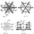
- a preferred layout with two anchor blocks 21a on opposite sides of the foundation and with a semi-circular (180-degree) tendon arrangement is shown in Fig. 13 .
- Ring tendons with ring anchors 59b (such as dog-bone anchors) can be used, with perimeter or circumferential tendons, to avoid having blisters on the foundation 100.
- Styrofoam block-outs 53a can be placed in the foundation 100 according to anchor manufacturer recommended dimensions. When the concrete reaches the sufficient strength ring tendons 58 are jacked and ring anchors 59b grouted.
- circumferential post tension may be made with multiple tiers of tendons 59 , in this case anchor block 21a locations or ring anchor 59b locations for each tier may be staggered around the perimeter of the foundation 100p to reduce stress concentration. Corrosion protection must be provided at anchor locations.
- Perimeter post-tensioning 112, or circumferential post-tensioning 59 can be made with bundled, un-bonded mono-strands without encapsulation.
- the foundation may be made with a network of prestressed concrete elements that can be structurally analyzed, with the strut and tie method.
- a three-dimensional structure made of an array of vertically and horizontally oriented truss-girders joined at the center may be used, with major tension chords reinforced with prestrssing tendons, based on both upwind and downwind load cases.
- the tension forces in the structure are resisted largely by prestressing elements and passive reinforcing. Compression forces are resisted largely by the concrete elements.
- the structure can be analyzed as a circumferential array of vertically oriented trusses that are fixed at their inner ends 16c to the central pedestal 10 and are laterally stabilized at their bottom by a horizontal trussed diaphragm formed by perimeter post tensioning 59a, in the slab 20 or perimeter beam 190, and radial bottom tendons 58 in the ribs 16 or the slab 20.
- the fatigue resistant foundation 100 comprises a circumferential array of vertically oriented eccentrically prestressed cantilevered girders 16 that are fixed at their inner ends 16c to a central pedestal 10 that is laterally supported and confined through most of its height by rib concrete, and the ribs 16 and pedestal 10 are laterally stabilized at their bottom by a horizontal prestressed concrete trussed diaphragm, with a continuous slab 20, and the prestressing is provided by radial tendons in the ribs 16 (or the slab 20) and circumferential post tensioning elements 59.
- the radial 58, 110, 111 and circumferential 59 tendons provide eccentric prestressing in the ribs 16 and the pedestal 10.
- the pedestal 10 is vertically prestressed by an array of vertically extending anchor bolt circle 60 and is structurally fixed to a tower base 301 of a pylon.
- the construction of the foundation 100 may utilize pre-assembled slab perimeter reinforcing cages 21c, built in segments with overlapping spliced bars at their ends, and each having an array of shear resisting vertical ties 21vt and flexure resisting horizontal bars 21h as well as anchor zone reinforcing.
- Slab perimeter cages 21c or perimeter beam reinforcing cages, 190c can be preassembled and then placed in the foundation.
- the foundation has specific reinforcing groups.
- the ribs 16 have flexure reinforcing tendons 58 concentrated at the bottom and the top, vertical stirrups 16vt for shear reinforcing tightly spaced in high shear zones along rib inner end 16c, rib skin reinforcing on each face 16fs and bursting and splitting reinforcing made of horizontal hairpins 16hp extending between the rib skin reinforcing 16fs, as well as straight, hooked or U-shaped horizontal dowels 46 for embedment into the pedestal 10 and vertical dowels 42, at the bottom of the ribs 16 are used, for composite action with the slab 20.
- the vertical stirrups 16vt also function as dowels for composite action of the slab 20.
- the dowels may be spaced such that they mesh between slab reinforcing bars without geometric interference.
- the rib reinforcing 16rc is built in preassembled cages and placed over the slab reinforcing 22,24. In order to maximize shear capacity vertical stirrups are placed side-by-side, in pairs, at the inner rib zone 16c where the shear demand is high.
- Anchor zones as shown in Fig. 5 , are provided with heavy reinforcing with trim bar and ties 16tt as well as surface reinforcing at anchor block location.
- the ribs 16 may also have horizontal reinforcing dowels 45, perpendicular to the ribs 16, to facilitate the structural continuity of the supported perimeter beams 190 or the thickened slab, across the width of the rib 16, by means of splicing the dowels 45 with perimeter reinforcing.
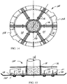
- the pedestal 10 as shown in Fig. 11 and Fig. 12 , has a horizontal mesh 50t at the top and skin reinforcing 50c1 at all surfaces as well as at least one cage 50, around the anchor bolt assembly 60, comprising vertical tightly meshed bursting reinforcing 50c including two cylindrical meshes 50c1 & 50c2 confining the anchor bolts 56 each comprising horizontal hoops 50c1h & 50c2h and either C or Z-Shaped bars 50cv and a radial array of horizontal hair-pins 16hp or stirrups tying both cylindrical meshes 50c1 & 50c2 or spiral stirrups each housing a number of anchor bolts 56.
- the pedestal 10 cage assembly may comprise two concentric tightly meshed cages 50c1 & 50c2 surrounding the anchor bolts 56 one from the inside and the other from the outside with a radial array of bursting and splitting resistant hairpins extending between the two cages 50c1 and 50c2. Additionally an array of vertically oriented pedestal 10 vertical bursting out of plane stress resistant reinforcing group of reinforcing elements, comprising circumferentially spaced vertical hairpins 50vt extending between said top horizontal mesh 50t and a horizontal bottom reinforcing mesh 50b in the pedestal 10 or slab 20, is included in the pedestal cage.
- the vertical hairpins 50vt in pedestal core 10a also function as supports to secure tendons in the pedestal 10 during construction.
- Upper 50t and lower 50b slab reinforcing meshes may have any pattern such as a square grid, a circular array with radial pattern or overlapping pie-shaped segments. Additionally, there may be an array of slab reinforcing 22, 24 locally arranged beneath the ribs 16 oriented parallel to the ribs 16 and extending into the pedestal 10 to facilitate composite action.
- the slab 20 may also be reinforced with post-tensioning elements in any pattern including radial, circumferential, perimeter or a square grid.
- the foundation may utilize many prefabricated components including rebar meshes and cages, pedestal cage assembly, pre cut post-tensioning strands, preassembled post-tensioning bundles, pre-cut post-tensioning duct sections and prefabricated concrete forms.
- Reusable rib forms 16b may be utilized to form the foundation perimeter, the ribs 16 and the pedestal. Forms can be made to be segmented, universal, expandable and adjustable to work for different foundation sizes. Rib forms 16b can be made with adjustable supports to elevate the forms above the wet slab concrete during construction if the foundation is built in one pour. Rib forms 16b may sit directly on the hardened concrete slab 20 if the foundation is built in two pours. Rib forms 16b may be made with two side-panels of stiffened non-stick plates and an array of adjustable horizontal spacers between the panels to maintain proper geometry and resist the lateral pressure of wet concrete.
- Rib and pedestal forms 102 may be fitted with lifting lugs 32 or means for receiving and supporting ladders, catwalks 95 and work platforms 95 to allow for access around the foundation.
- the forms may have means for securing post-tension anchors and hardware at specific spacing during construction.
- the forms may also have means for hanging and supporting rib reinforcing cages.
- the foundation 100 may be supported on piles, or micro-piles 401 or piers 402or rammed-aggregate piers 405.
- the foundation 100 may receive rock anchors 404 or soil-anchors in a conventional manner.
- a construction site is prepared by excavation, grading and compaction soil for the foundation.
- the foundation 100 may be set on a mud slab or on compacted granular fill.
- the mud slab is a thin plain concrete layer intended to provide a clean and level base for foundation installation.
- the slab reinforcing is placed inside slab forms 17 and the slab is poured in place with dowels 42 extending up from the slab 20 to receive the ribs 16 and the pedestal 10 in a second pour.
- the rib and pedestal rebar 50 and cage placement with post-tension tendons (or duct) placement are set in place and forms are installed before a second pour is carried out.
- the foundation 100 can be poured in a single pour with the use of accelerators in the concrete mix and by following a well designed concrete pour sequence.
- a set of small footings 16f, placed within the mud slab, can be used to support and elevate the rib forms 16b and pedestal forms 102 during construction.
- Slab 20 pedestal and rib reinforcing elements are assembled in the foundation 100. Forms are placed in the foundation around the perimeter, the ribs 16 and the pedestal 10 and the concrete is poured into the foundation in a carefully designed pour sequence. One option is to start with slab 20 and the bottom part of the ribs 16 and the pedestal with accelerator in the concrete mix to seal the bottom of rib and pedestal forms 102 by the time the slab 20 concrete is finished, the ribs 16 and the pedestal are poured jointly in small lifts.
- the post-tension elements are jacked and grouted as required.
- the tower base flange 301 is then attached to the pedestal 10 and grouted, and the tower anchor bolts are tensioned after the grout reaches sufficient strength.
- the invention relates to a high stiffness, fatigue resistant, wind turbine foundation 100, supporting a wind generator with a multi-megawatt rating and subjected to extremely high cyclical upset loads that comprise the following components comprising:
- slab post-tensioning can be arranged at any combination of perimeter, radial or diametric, or other patterns.
- composite action is further facilitated with radially oriented, reinforcing bars 24r1 locally arranged in the slab 20, beneath the ribs 16, and extended deep into the pedestal 10, in addition to an array of vertical dowels extending between the rib and the slab 20 that function as shear connectors.
- the invention pertains to a foundation 100 for supporting a wind generator with a multi-megawatt rating and subjected to extremely high cyclical upset loads, with increased stiffness and improved fatigue resistant comprising:
- the rib extends vertically from the bottom of the foundation to an elevation near the bottom of the tower base flange 301 to enable the ribs 16 to participate in resisting bearing loads under the tower base flange by increasing the area of the cross-section involved in bearing resistance under the tower base flange 301 and increasing the permissible bearing strength under the base flange or the grout bed 90a and by increasing the bearing area measured at the surrounding faces of the concrete.
- the geometric configuration and the improvement in bearing resistance allow concrete with only one relatively low compressive-strength for the entire foundation structure. In contrast, high bearing stresses under the tower base flange 301 in conventional gravity spread footings, requiring concrete with higher compressive strength for the pedestal and a lower compressive strength for the base.
- the proximity of inner rib ends to the tower base flange 301 allows the inner zones of the ribs 16 to remain under vertical compression stresses caused by vertical post-tensioning forces between embedment ring 54 and tower base flange 301.
- the vertical compression stress zones 10x improves confinement conditions and fatigue resistance in the rib inner zones 16c.
- Bonded and grouted multi-strand in some applications may be too expensive and take too long to install as it requires an additional step of grouting and may not be economical for some onshore installations. It may then be preferable to use un-bonded, encapsulated mono-strands, arranged in bundles and installed in the foundation reinforcing prior to concrete casting, which reduces construction costs and improves the construction schedule.
- post-tensioning in the foundation 100 is made eccentric, to create cambers in the foundation 100 that could result in reduced deflections and improved foundation-soil contact.
- the eccentric prestressing of the ribs 16 creates a convex shaped camber in the foundation 100 that helps reduce the deflections under turbine weight and operating loads.
- cambers can be used in perimeter beams 190 and slab sections to reduce slab deflections and improve foundation-soil contact conditions by ensuring a more uniform bearing pressure under the foundation thus allowing for an optimized foundation footprint with more uniform pressure over effective area.
- the vertical profile (elevation) of circumferential tendons in the foundation 100 may be varied at mid spans and under supporting ribs 16 to optimize their utilization.
- a gradual transition of geometry at the conjunction of the structural elements is employed to prevent stress concentration and fatigue related problems.
- the use of fillets and curved transition ft is desirable at the conjunctions between ribs 16, pedestal 10 and the slab 20.
- the inner ends of the ribs 16 are tapered to a wider cross-section as the rib connects to the pedestal 10, in order to satisfy the high flexural, torsional and shear demands at the inner zone of the ribs 16, and to distribute the multi-axial compression over large surface area to help reduce splitting and bursting reinforcing on the side of the pedestal 10.
- low relaxation post-tensioning strands are used to reduce post tension losses over time.
- Concrete accelerators and plasticizers and other admixtures may be utilized in the concrete mix design.
- the small thickness of the structural elements may allow for on-site steam curing of concrete.
- a hollow pedestal 10 cross-section may be used, however it can be problematic.
- a hollow pedestal above the frost depth where there is elevated water table may be problematic.
- a hollow pedestal results in reduced stiffness, stress discontinuity, and will have indirect load transfer and stress concentrations with local deformations in the shell resulting in poor performance under heavy flexural and torsional loads from the cantilevered rib, as well as additional problems stemming from stresses caused by frost forming and freezing of ground water in the foundation.
- the cross-section of the rib may change and dimensions along its length may change.
- the section may start rectangular and gradually a top flange may be enlarged to reduce stresses in the upper zone of the rib.
- the pedestal 10 may have an enlarged cross-section at the top followed by a transition into a smaller cross-section below.
- the upper enlarged cross-section may help improve bearing strength at the top of the pedestal below the tower base flange 301a, the bearing washer plate 404b, and the high strength grout bed 90a according to American Concrete Institute design guidelines.
- the present invention pertains to a foundation design that overcomes the thermal cracking problem stemming from heat of hydration, in large foundation pours, by using a structural configuration coupled with post-tensioning techniques that reduce the thickness of the structural elements, while increasing the surface area of the concrete pour, thus improving heat dissipation conditions and causing a the ratio of concrete mass to surface area to be roughly 40% to 50% less than in conventional design for inverted T foundations for the same turbine under the same loading and geotechnical conditions.
- a tower base leveling and grouting method can be used which does not employ tower anchor bolts for leveling, or leveling shims which cause undesirable stress concentration at shim locations which could lead to localized fatigue failure at shim locations.
- the new method employs the bolt template 52 at the very top of the bolt assembly with at least three sets of additional leveling bolts 53 and corresponding threaded bolt inserts 53b suitable for embedment into concrete.
- the leveling bolts 53 and inserts 53b may be located outside or inside the bolt circle 60a of tower base, but directly under tower base flange 301a. This allows for continuity of grout bed 90a construction and provides an easy access for leveling bolts 53.
- Small cutouts 53a connected at leveling bolt locations can be used. Another benefit of this leveling technique is having the ability to apply a continuous grout bed 90a that is free of construction joints, under tower base 301 in one session and to have the ability to tension all the anchor bolts in one session.
- the present invention improves safety and accessibility around foundations during construction, and reduces hazardous conditions for construction crews. This goal is achieved by using reusable form sections 102 that are fitted with platform sections for forming access platform around the foundation.
- the form may also connect to at least one access ramp extending beyond the edge of the foundation.
- the platform and the ramp 95 are fitted with a slip-resistant walking surface and the elevated ramps are provided with guardrails and designed to applicable industry safety standards. Further, the relatively thin slab thickness minimizes the risk of worker injury during construction.
- a transformer pad can be supported on precast concrete posts extending vertically from the foundation.
- Pedestal forms 102 may have openings 102a for running electrical and communication conduits 250 there through thus preventing problems stemming from randomly placing the conduits 250 in areas that could compromise the structural design.
- the ribs 16 may have means for receiving and supporting prefabricated trays (or electrical duct banks) for housing power and communication cables.
- the foundation design can also be adapted for offshore wind turbine projects.
- the foundation 100 may be assembled on a barge or dry dock then transported or floated to its destination, and lowered into a prepared seabed location. The foundation can be weighed down in place by backfilling it with suitable material.
- the offshore foundation 100 may be configured to receive any type of offshore piers 404, suction piers 403, piles 400, micro-piles 401, anchors 404 or any combination of the above.
- an offshore concrete foundation 100 with high stiffness and improved fatigue resistant comprising:
- the said post-tensioning elements are jacked and the anchor bolts are post-tensioned such that the foundation is kept under heavy multi-axial post-compression.
- the offshore foundation 100 is constructed on a barge or in a dry dock and then floated or transported to an offshore installation site and lowered to be placed over a prepared sea bed.
- a suitable backfill material 13 is placed over the foundation 100 to stabilize the foundation against overturning.
- Scour protection measures 13b are provided around the foundation.
- the foundation may be built with marine cement and marine grout and kept under heavy multi-axial horizontal and vertical pre-stress using bonded and grouted post tensioning systems rated for double corrosion protection and suitable for a marine environment.
- an offshore foundation for wind turbines comprises the following elements:
- Radial post-tensioning tendons extend from the distal end of one rib through the rib and the pedestal to the distal end of the opposite rib. Vertical post-tensioning is arranged in the pedestal 10 as well. The stem 11 and the ice cone 11b may also benefit from circumferential post-tensioning 59t.
- the pedestal 10 has means for receiving and supporting a tower 300 or pylon.
- the upper portion of the pedestal 10 (the stem 11) may be made in multiple consecutive cast in situ pours, depending on its height.
- the stem 11 may be made by joining precast segments with circumferential 59t and vertical 70 post-tensioning to form the stem 11 as in segmented concrete tower construction..
- a wind turbine may be fabricated on a barge with precast concrete elements.
- the barge surface is prepared with a non bonding agent or a thin membrane at the foot print where the foundation is to be built.
- Lower slab reinforcing mesh sections are assembled and placed on the barge and the pedestal cage reinforcing is assembled at the center of the foundation.
- Upper slab reinforcing mesh sections 24 may follow after the slab post tension duct 58dc is placed.
- Precast concrete ribs 16 are placed in a radial array around the pedestal cage 50 and precast concrete perimeter beams 190 are arranged around the perimeter of the foundation 100p.
- Post tensioning ducts 58dc in the pedestal space 10 and at perimeter beam-to-rib connections 59dc are placed to pair with their corresponding duct in the precast members.
- Forms for the pedestal 10 and for closure pours at rib-to-perimeter beam connections are installed.
- the slab concrete is poured followed by pedestal 10 concrete and closure pours at the rib-to-pedestal connections.
- the stem 11 is fabricated possibly in multiple consecutive pours depending on pedestal height.
- the stem 11 design may incorporate an ice cone 11b at its top.
- the post tensioning tendons 500 are then installed.
- the jacking and grouting of tendons is then carried out.
- Some pylon sections may be installed prior to transportation.
- the finished foundation 100 is transported to its offshore installation site using a suitable means of transportation such as towing the barge.
- offshore foundation for comprises the following elements as shown in Fig. 46 :
- Radial post-tensioning tendons extend from rib ends 50 opposite rib ends across the pedestal 10. Vertical post-tensioning is arranged in the pedestal 10 as well. The structural behavior is improved by the added compression in all ribs 16, edge beams, slab 20 and center pedestal.
- the lattice tower 200 preferably incorporating 3-dimentional trusses 200tr, transfers the pylon loads down to the concrete foundation 100.
- the lattice tower 200 may get connected to the concrete foundation prior to transportation or it can be connected to the foundation at final offshore installation site.
- a wind turbine foundation is fabricated on a barge with precast concrete element as following.
- the barge surface is coated with a non-bonding agent or covered with a thin membrane at the foot print where the foundation is to be built.
- Lower slab reinforcing mesh sections are assembled and placed in the slab area and the pedestal cage reinforcing is assembled at the center of the foundation.
- Upper slab reinforcing mesh sections may follow after the slab post tension ducts are placed.
- Precast concrete ribs 16 are placed in a radial array around the pedestal cage 50 and precast concrete perimeter beams 190 are arranged around the perimeter of the foundation 100p.
- Post tensioning ducts in the pedestal space and at perimeter beam-to-rib connections are placed to pair with corresponding duct in the precast members.
- Forms for the pedestal and for closure pours at the rib-to-perimeter beam connections are installed.
- Slab concrete is poured followed by pedestal concrete and closure pours at rib-to-pedestal connections.
- a lattice tower 200 structure is prefabricated and mounted atop the concrete foundation 100. The foundation is transported to the installation site using a suitable means of transportation. The seabed is prepared for receiving the foundation by placing a sub-base of suitable material such as crushed stone. The foundation is backfilled and scour protection measures 13b are installed.
- the stem 11 is prefabricated separately and provided with a means for connecting to the pedestal 10, preferably an array of vertical post tensioning dowels 60 extended through the pedestal 10 and the stem 11 or other segmental post tensioning joining methods may be used.
- the pedestal may be fitted with a means for receiving the prefabricated stem 11 based on segmental post tensioning and grouting construction methods.
- Piles 400, Micro-piles 401 or piers 402 or suction piers 403 or anchors 404 can be used with the offshore foundation 100 in a similar manner as previously described in the application.
- vertical sleeves will be arranged in the foundation to receive an array of piles 400 or anchors 404 extending through the foundation, to allow for additional loading capacity and improve the stability of the foundation.
- Piles 400 are secured to the foundation by filling the sleeves with marine grout.
- the use of piles 400, piers 402 or suction piers 403 or anchors 404 may eliminate the slab 20 and/or the perimeter beams 190 from the design.
Claims (23)
- Fundament, aufweisend:eine Betonträgerplatte, die ein darin befindliches horizontales Armierungsgitter aufweist,einen Betonsockel, der mit der Trägerplatte integral ist und darin befindliche, zum vertikalen nachträglichen Vorspannen dienende Elemente aufweist,eine Mehrzahl von Betonrippen, die sich auf der Oberseite der Trägerplatte befinden und integral mit dieser sowie integral mit dem Sockel sind, wobei die Rippen darin befindliche Armierungen aufweisen und sich von dem Sockel nach außen erstrecken, wobeider Sockel, die Platte und die Rippen miteinander verbunden sind, um ein monolithisches Fundament zu bilden.
- Fundament für eine Turmstruktur nach Anspruch 1, wobei das Fundament (100) ein für ein nachträgliches Vorspannen dienendes Element (58, 110) in den Rippen (16) beinhaltet.
- Fundament für eine Turmstruktur nach Anspruch 1 oder 2, wobei das Fundament (100) ein für ein nachträgliches Vorspannen dienendes Element (111) in der Platte (20) beinhaltet.
- Fundament für eine Turmstruktur nach den Ansprüchen 1 bis 3, wobei der Sockel (10) vertikale Ankerbolzen (56) für ein vertikales nachträgliches Vorspannen und für ein Verbinden einer Turmbasis mit dem Fundament beinhaltet.
- Fundament für eine Turmstruktur nach Anspruch 4, wobei das Fundament (100) einen Einbettungsring (54) in der Nähe der Basis des Sockels (10) und eine Turmbasis an der Oberseite des Sockels (10) beinhaltet, wobei sich die vertikalen Ankerbolzen (56) zwischen dem Einbettungsring (54) und der Turmbasis erstrecken, und zwar für ein vertikales nachträgliches Vorspannen des Fundaments (100).
- Fundament für eine Turmstruktur nach den Ansprüchen 1 bis 5, wobei ein vertikaler Schaft (11) an dem Sockel (10) befestigt ist.
- Fundament für eine Turmstruktur nach Anspruch 6, wobei für ein nachträgliches Vorspannen dienende Elemente (70) sich von dem Sockel (10) durch den Schaft (11) hindurch erstrecken, für ein Vorspannen des Sockels (10) und des Schaftes (11).
- Fundament für eine Turmstruktur nach den Ansprüchen 1 bis 7, wobei die Platte (20) einen Umfangsträger (190) oder verdickte Plattenkanten (21) aufweist, um das Fundament (100) zu versteifen.
- Fundament für eine Turmstruktur nach Anspruch 8, wobei ein für ein nachträgliches Vorspannen dienendes Element (58) in dem Umfangsträger (190) oder den verdickten Plattenkanten (21) zur Verstärkung des Fundamentes (100) dient.
- Fundament für eine Turmstruktur nach den Ansprüchen 1 bis 9, wobei die Rippen (16) in Paaren vorliegen, die sich auf gegenüberliegenden Seiten des Sockels (10) befinden.
- Fundament für eine Turmstruktur nach Anspruch 10, wobei die für ein nachträgliches Vorspannen dienenden Elemente (58) sich durch eine Rippe (16) hindurch und durch den Sockel hindurch erstrecken, und zwar zu der von der Rippe aus gegenüberliegenden Seite des Sockels.
- Fundament für eine Turmstruktur nach Anspruch 10, wobei die für ein nachträgliches Vorspannen dienenden Elemente (58) sich durch eine Rippe (16) des Sockels (10) und die Rippe (16) auf der gegenüberliegenden Seite des Sockels hindurch erstrecken.
- Fundament für eine Turmstruktur nach den Ansprüchen 1 bis 11, wobei Sockelkäfige (50) in dem Sockel (10) verwendet werden.
- Sockel für eine Turmstruktur nach den Ansprüchen 1 bis 12, wobei die Rippen (16) in Form eines Fachwerks vorliegen.
- Fundament für eine Turmstruktur nach den Ansprüchen 2 bis 13, wobei das nachträgliche Vorspannen asymmetrisch erfolgt, um dem Fundament Balligkeit zu verleihen.
- Verfahren zur Erstellung eines Fundaments, das eine Platte, einen Sockel und eine Mehrzahl von Rippen aufweist, beinhaltend:Ausheben einer Baugrube, um einen Baugrund freizulegen, Verdichten und Planieren des Baugrundes, Platzieren eines Auflagermaterials auf dem Baugrund,Installieren von Armierung und Dübeln auf dem Auflagermaterial, damit sich die Armierung durch die Platte hindurch und in den Sockel hinein erstreckt, um die Platte mit dem Sockel zu verbinden, und sich die Dübel in den Sockel hinein erstrecken, um die Platte mit dem Sockel zu verbinden, und sich die Dübel von der Platte in die Rippen hinein erstrecken, um die Platte mit den Rippen zu verbinden,Platzieren eines Ankerbolzenkäfigs benachbart der Plattenarmierung, wobei der Ankerbolzenkäfig eine Anordnung von Ankerbolzen aufweist, die an ihrem unteren Ende mit einem Einbettungsring verbunden sind,Platzieren einer Sockelarmierung um den Ankerbolzenkäfig, wobei die Sockelarmierung horizontale Elemente und vertikale Elemente aufweist, die in Intervallen angeordnet sind,Platzieren einer Rippenarmierung, die sich durch die Rippen hindurch und in den Sockel hinein erstreckt, und von Rippendübeln, die sich von den Rippen aus in den Sockel erstrecken, um die Rippen mit dem Sockel zu verbinden,Installieren von Plattenschalungen, die gegossenen Beton aufnehmen sollen, um eine Platte auszubilden,Installieren von Sockel- und Rippenschalungen, welche den Bolzenkäfig, die Sockelarmierung und die Rippenarmierung umgeben und den gegossenen Beton aufnehmen sollen, um den Sockel und die Rippen zu erzeugen,Einfüllen von Beton in die Plattenschalungen, um die Platte zu erzeugen,dann Einfüllen von Beton in die Sockelschalungen und die Rippenschalungen, um den Sockel und die Rippen des Fundaments zu erzeugen,Entfernen der Plattenschalungen, der Rippenschalungen und der Sockelschalungen, nachdem das Aushärten des Betons erfolgt ist, und Hinterfüllen der Platte mit Verfüllmaterial, um zur Stabilisierung des Fundaments beizutragen.
- Verfahren zur Erstellung eines Fundaments, das eine Platte, einen Sockel und eine Mehrzahl von Rippen aufweist, nach Anspruch 16, wobei es weiter ein Verdichten des Verfüllmaterials beinhaltet.
- Verfahren zur Erstellung eines Fundaments, das eine Platte, einen Sockel und eine Mehrzahl von Rippen aufweist, nach Anspruch 17, wobei es weiter beinhaltet: Platzieren eines Turmbasisabschnitts mit einem Basisflansch, der Bolzenöffnungen für eine Aufnahme der Ankerbolzen des Ankerbolzenkäfigs auf der Oberseite des Sockels aufweist.
- Verfahren zur Erstellung eines Fundaments, das eine Platte, einen Sockel und eine Mehrzahl von Rippen aufweist, nach Anspruch 18, wobei es weiter beinhaltet, dass Einrichtungen auf der Oberseite des Sockels dafür vorgesehen werden, dass ein Zwischenraum zwischen dem Sockel und dem Turmbasisflansch vorhanden ist, und Mörtel darin platziert wird.
- Verfahren zur Erstellung eines Fundaments, das eine Platte, einen Sockel und eine Mehrzahl von Rippen aufweist, nach Anspruch 19, wobei es weiter beinhaltet, dass Muttern auf den Ankerbolzen platziert werden und ein Anziehen der Muttern erfolgt, nachdem der Mörtel ausreichend fest ist.
- Verfahren zur Erstellung eines Fundaments, das eine Platte, einen Sockel und eine Mehrzahl von Rippen aufweist, nach Anspruch 18, wobei es weiter beinhaltet, dass ein Windturmabschnitt auf der Oberseite des Turmbasisabschnitts platziert wird.
- Verfahren zur Erstellung eines Fundaments, das eine Platte, einen Sockel und eine Mehrzahl von Rippen aufweist, nach Anspruch 21, wobei es weiter beinhaltet, dass eine Windturbinenrotor-Gondelbaugruppe auf der Oberseite der Windturmabschnitte platziert wird.
- Verfahren zur Erstellung eines Fundaments, das eine Platte, einen Sockel und eine Mehrzahl von Rippen aufweist, nach Anspruch 16, wobei es weiter beinhaltet, dass das Fundament in einem einzigen kontinuierlichen Gießvorgang gegossen wird.
Applications Claiming Priority (6)
| Application Number | Priority Date | Filing Date | Title |
|---|---|---|---|
| US21543009P | 2009-05-05 | 2009-05-05 | |
| US26980009P | 2009-06-29 | 2009-06-29 | |
| US28490109P | 2009-12-28 | 2009-12-28 | |
| US33955010P | 2010-03-05 | 2010-03-05 | |
| US12/774,727 US20110061321A1 (en) | 2006-09-21 | 2010-05-06 | Fatigue reistant foundation system |
| PCT/US2010/041006 WO2010138978A2 (en) | 2009-05-05 | 2010-07-05 | Fatigue resistant foundation |
Publications (3)
| Publication Number | Publication Date |
|---|---|
| EP2427603A2 EP2427603A2 (de) | 2012-03-14 |
| EP2427603A4 EP2427603A4 (de) | 2016-09-07 |
| EP2427603B1 true EP2427603B1 (de) | 2018-03-14 |
Family
ID=43223415
Family Applications (1)
| Application Number | Title | Priority Date | Filing Date |
|---|---|---|---|
| EP10781394.1A Revoked EP2427603B1 (de) | 2009-05-05 | 2010-07-05 | Ermüdungsfestes fundament |
Country Status (3)
| Country | Link |
|---|---|
| US (1) | US8661752B2 (de) |
| EP (1) | EP2427603B1 (de) |
| WO (1) | WO2010138978A2 (de) |
Families Citing this family (61)
| Publication number | Priority date | Publication date | Assignee | Title |
|---|---|---|---|---|
| US8661752B2 (en) | 2006-09-21 | 2014-03-04 | Ahmed Phuly | Foundation with slab, pedestal and ribs for columns and towers |
| IT1400073B1 (it) * | 2009-09-11 | 2013-05-17 | Stefano Knisel | Fondazione migliorata per torre eolica |
| IT1396433B1 (it) * | 2009-11-16 | 2012-11-23 | Rolic Invest Sarl | Impianto eolico per la generazione di energia elettrica e metodo per realizzare un pilone del suddetto impianto eolico. |
| US9394035B2 (en) * | 2010-11-04 | 2016-07-19 | University Of Maine System Board Of Trustees | Floating wind turbine platform and method of assembling |
| BR112013011146B1 (pt) | 2010-11-04 | 2021-01-12 | University Of Maine System Board Of Trustees | plataforma de turbina de vento semissubmersível capaz de flutuar em um corpo de água e suportar uma turbina de vento |
| CN102251532B (zh) * | 2011-04-20 | 2012-11-28 | 上海交通大学 | 底面为曲面基础优化施工方法 |
| US20120023860A1 (en) * | 2011-05-25 | 2012-02-02 | General Electric Company | Adapter Configuration for a Wind Tower Lattice Structure |
| GB2494674B (en) * | 2011-09-15 | 2018-09-05 | Ronald Chambers Peter | A connection formed under water between a wind turbine tower and a wind turbine foundation |
| DE102011087022A1 (de) * | 2011-11-24 | 2013-05-29 | Wobben Properties Gmbh | Vorrichtung und Verfahren zum Verankern einer Windenergieanlage |
| KR101447108B1 (ko) * | 2012-09-20 | 2014-10-06 | 한국해양과학기술원 | 해상풍력 지지구조 |
| FI20126086L (fi) | 2012-10-18 | 2014-04-19 | Stx Finland Oy | Offshore-rakenne |
| DE102013002472A1 (de) * | 2013-02-13 | 2014-08-14 | Strabag Offshore Wind Gmbh | "Schwerkraftfundament für ein Offshore-Bauwerk" |
| WO2014160951A1 (en) * | 2013-03-29 | 2014-10-02 | Tindall Corporation | Core component and tower assembly for a tower structure |
| CN205688927U (zh) * | 2013-05-10 | 2016-11-16 | 艾瑞电信公司 | 用于单极子的底座和单极子结构 |
| US10227786B2 (en) * | 2013-08-08 | 2019-03-12 | University Of Utah Research Foundation | Elongate member reinforcement with a studded collar |
| US9976315B2 (en) * | 2013-08-08 | 2018-05-22 | University Of Utah Research Foundation | Elongate member reinforcement |
| DE102013216343A1 (de) * | 2013-08-19 | 2015-02-19 | Wobben Properties Gmbh | Windenergieanlagen-Fundament und Windenergieanlage |
| DE102013217128A1 (de) | 2013-08-28 | 2015-03-05 | Wobben Properties Gmbh | Rotorblattelement für eine Windenergieanlage, Rotorblatt, sowie ein Herstellungsverfahren dafür und Windenergieanlage mit Rotorblatt |
| US9003721B1 (en) † | 2013-11-08 | 2015-04-14 | Siemens Aktiengesellschaft | Leveling arrangement for a tower |
| US8919051B1 (en) * | 2013-12-02 | 2014-12-30 | Abel Echemendia | Tower with exterior cable support and a modular base |
| CN106029987A (zh) * | 2014-01-16 | 2016-10-12 | 帕卡达尔有限公司 | 风力涡轮机塔架的基座和风力涡轮机塔架的预组装方法 |
| ES2548297B9 (es) * | 2014-02-18 | 2021-01-15 | Inneo Torres Sl | Zapata prefabricada para torres eólicas |
| CN104088291A (zh) * | 2014-05-05 | 2014-10-08 | 安徽三建工程有限公司 | 一种环形楔块组合式混凝土预制块塔吊基础 |
| US9617704B2 (en) * | 2014-05-27 | 2017-04-11 | One Energy Enterprises Llc | Reinforcement assemblies, fixtures, and methods |
| ES2524840B1 (es) * | 2014-06-06 | 2015-09-08 | Esteyco S.A.P. | Sistema de cimentación para torres y procedimiento de instalación del sistema de cimentación para torres |
| EP3169849B1 (de) * | 2014-07-18 | 2019-10-16 | Henry Obermeyer | System und verfahren zur verankerung einer wehr zur regelung der wasserstandshöhe |
| US9783950B2 (en) | 2014-10-07 | 2017-10-10 | Allan P. Henderson | Retrofit reinforcing structure addition and method for wind turbine concrete gravity spread foundations and the like |
| WO2016132166A1 (en) * | 2015-02-20 | 2016-08-25 | Soletanche Freyssinet | Method of building a foundation comprising a steel monopile and a concrete part and associated foundation for construction work |
| WO2016149780A1 (pt) * | 2015-03-26 | 2016-09-29 | Paulo Emmanuel De Abreu | Fundação híbrida para torres |
| IN2015MU02042A (de) * | 2015-05-26 | 2015-06-05 | Yashraj Mahesh | |
| US9915267B2 (en) * | 2015-06-08 | 2018-03-13 | Air Distribution Technologies Ip, Llc | Fan inlet recirculation guide vanes |
| EP3320170B1 (de) | 2015-07-12 | 2021-01-20 | Isims LLC | Strukturträgersystem und verfahren zur verwendung |
| CN107923136A (zh) | 2015-07-15 | 2018-04-17 | 鲁特基础系统公司 | 用于塔架的梁和桩锚固基座 |
| EP3203065B1 (de) * | 2016-02-02 | 2019-07-03 | Dywidag Sistemas Constructivos, S.A. | Windturmverbindungssystem |
| AT517958B1 (de) * | 2016-02-18 | 2017-06-15 | Holcim Technology Ltd | Fundament für ein Windrad |
| AT517959B1 (de) * | 2016-02-18 | 2017-06-15 | Holcim Technology Ltd | Fundament für ein Windrad |
| AT519189B1 (de) * | 2016-09-26 | 2020-04-15 | Holcim Technology Ltd | Fundament für eine Windmühle |
| AT519190A1 (de) * | 2016-09-26 | 2018-04-15 | Holcim Technology Ltd | Fundament für eine Windmühle |
| ES2673105B1 (es) | 2016-12-19 | 2019-03-26 | Siemens Gamesa Renewable Energy Innovation & Technology SL | Método de construcción de la cimentación de una torre |
| AU2018356013A1 (en) * | 2017-10-25 | 2020-04-30 | Rute Foundation Systems, Inc. | Tower foundation with concrete box girder beams |
| US11661718B2 (en) | 2018-07-25 | 2023-05-30 | Terracon Consultants, Inc. | Concrete pier foundation with lateral shear reinforcing loops and methods of constructing the same |
| US10988909B1 (en) | 2018-08-29 | 2021-04-27 | RCAM Technologies, Inc. | Additive manufacturing of support structures |
| EP3861174A4 (de) | 2018-10-04 | 2022-05-18 | Tetra Tech, Inc. | Windturbinenfundament und verfahren zum bau eines windturbinenfundaments |
| CN109281332A (zh) * | 2018-11-06 | 2019-01-29 | 重庆大学 | 一种基于组合结构的风电塔筒基础环肋梁式基础 |
| US11365523B2 (en) * | 2018-11-13 | 2022-06-21 | Terracon Consultants, Inc. | Methods for constructing tensionless concrete pier foundations and foundations constructed thereby |
| NL2022433B1 (en) * | 2019-01-22 | 2020-08-18 | Koninklijke Bam Groep Nv | Method for manufacturing a gravity based foundation for an offshore installation, and gravity based foundation. |
| US11885092B2 (en) | 2019-01-31 | 2024-01-30 | Terracon Consultants, Inc. | Reinforcement structures for tensionless concrete pier foundations and methods of constructing the same |
| US11274412B2 (en) | 2019-01-31 | 2022-03-15 | Terracon Consultants, Inc. | Reinforcement structures for tensionless concrete pier foundations and methods of constructing the same |
| US10634122B1 (en) | 2019-02-08 | 2020-04-28 | Are Telecom Incorporated | Portable monopole tower with adjustable foundation |
| DE102019103984A1 (de) * | 2019-02-18 | 2020-08-20 | Wobben Properties Gmbh | Windenergieanlagen-Komponente für einen Windenergieanlagen-Turm und Verfahren |
| AT522250A1 (de) * | 2019-02-28 | 2020-09-15 | Holcim Technology Ltd | Fundament für eine Windkraftanlage |
| CN109826224A (zh) * | 2019-03-08 | 2019-05-31 | 中国能源建设集团安徽省电力设计院有限公司 | 一种用于沙漠地带输电线路铁塔的沉井护壁掏挖基础及其施工方法 |
| FR3093741B1 (fr) * | 2019-03-13 | 2021-04-30 | Cte Wind Civil Eng | Procédé de terrassement d’une fondation pour éolienne terrestre |
| DE102019107266A1 (de) * | 2019-03-21 | 2020-09-24 | Wobben Properties Gmbh | Gründung für ein Turmbauwerk, Turm für eine Windenergieanlage und Windenergieanlage sowie Verfahren zur Gründung eines Turmbauwerks |
| KR102134926B1 (ko) * | 2019-07-04 | 2020-07-16 | 한국건설기술연구원 | 가새형 버팀구조와 수평긴장장치를 이용한 기초보강장치 및 이를 이용한 기초보강방법 |
| EP3994312B1 (de) * | 2019-07-04 | 2024-04-03 | Vestas Wind Systems A/S | Verfahren zur herstellung eines windturbinenfundaments |
| CN113073791A (zh) * | 2021-04-07 | 2021-07-06 | 上海市城市建设设计研究总院(集团)有限公司 | 用于装配式结构的束筋连接灌浆套筒 |
| CN113293795A (zh) * | 2021-05-31 | 2021-08-24 | 中国电建集团青海省电力设计院有限公司 | 一种盐湖区输电线路铁塔基础施工方法 |
| KR102382028B1 (ko) * | 2021-12-02 | 2022-04-01 | (주)진영컨설턴트 | 토탈리프팅에 의한 보강파일 선행하중 재하 방법 |
| US20230295891A1 (en) * | 2022-03-17 | 2023-09-21 | Rute Foundation Systems, Inc. | Post-tensioned wind turbine foundation |
| CN116630428B (zh) * | 2023-07-24 | 2023-10-03 | 浩科机器人(苏州)有限公司 | 基于机器视觉的浇注位置识别方法及系统 |
Citations (9)
| Publication number | Priority date | Publication date | Assignee | Title |
|---|---|---|---|---|
| US3922823A (en) | 1973-11-01 | 1975-12-02 | Jimmie D King | Enclosed concrete water reservoir supporting earthfill for multiple land uses |
| US5586417A (en) | 1994-11-23 | 1996-12-24 | Henderson; Allan P. | Tensionless pier foundation |
| US20020124502A1 (en) | 2000-09-27 | 2002-09-12 | Henderson Allan P. | Perimeter weighted foundation for wind turbines and the like |
| US6467233B1 (en) | 2000-11-09 | 2002-10-22 | Beaird Industries, Inc | Wind tower |
| WO2005095792A1 (de) | 2004-04-02 | 2005-10-13 | Aloys Wobben | Verfahren zum errichten eines turmes |
| WO2007130667A2 (en) | 2006-05-05 | 2007-11-15 | Henderson Allan P | Post-tension pile anchor foundation and method therefor |
| US20080072511A1 (en) | 2006-09-21 | 2008-03-27 | Ahmed Phuly | Partially prefabricated modular foundation system |
| CN101560774A (zh) | 2009-05-20 | 2009-10-21 | 赵正义 | 大型塔桅式机械设备的组合基础 |
| US8661752B2 (en) | 2006-09-21 | 2014-03-04 | Ahmed Phuly | Foundation with slab, pedestal and ribs for columns and towers |
Family Cites Families (13)
| Publication number | Priority date | Publication date | Assignee | Title |
|---|---|---|---|---|
| FR1015719A (fr) * | 1950-03-25 | 1952-10-20 | Socle pour poteaux | |
| DE7637601U1 (de) * | 1976-12-01 | 1977-03-31 | Stewing, Albert, 4270 Dorsten | Vorgefertigtes koecherfundament |
| DE3336655C2 (de) * | 1983-10-08 | 1995-07-27 | Karl Munte Betonwerke Gmbh | Gießform und Verfahren zur Herstellung eines Köcherfundament |
| GB8811376D0 (en) * | 1988-05-13 | 1988-06-15 | Vidal H | Wall systems |
| DE4037438C2 (de) * | 1990-11-24 | 1996-01-18 | Bremer Gmbh | Transportables Stahlbetonfundament für eine Stütze |
| EP1058787B1 (de) * | 1998-02-27 | 2005-10-19 | Bonus Energy A/S | Verfahren zur installation einer windturbine ins meer, ein fundament für windturbinen und der gebrauch der fundamente |
| WO2000046452A1 (en) * | 1999-02-05 | 2000-08-10 | Northern Technologies, Inc. | Support structure for elevating and supporting monopoles and associated equipment |
| JP2001020849A (ja) * | 1999-07-09 | 2001-01-23 | Hitachi Zosen Corp | 水上風力発電装置 |
| EP1074663A1 (de) * | 1999-08-06 | 2001-02-07 | Carl Bro as | Fundament für Gebäude, insbesondere Fundament für einen Turm, Windenergieanlage oder dergleichen |
| DK174190B1 (da) * | 2000-04-12 | 2002-09-09 | Spaencom As | Fundament til vindmølle samt fremgangsmåde til montering heraf |
| JP3764643B2 (ja) * | 2000-10-23 | 2006-04-12 | 日立造船株式会社 | 洋上風力発電装置の基礎構造 |
| DE10321647A1 (de) * | 2003-05-13 | 2004-12-02 | Wobben, Aloys, Dipl.-Ing. | Fundament für eine Windenergieanlage |
| AU2003227292A1 (en) * | 2003-07-29 | 2005-02-17 | Chisholm, David Cameron | Reinforced concrete foundations |
-
2010
- 2010-07-05 US US13/319,083 patent/US8661752B2/en active Active
- 2010-07-05 EP EP10781394.1A patent/EP2427603B1/de not_active Revoked
- 2010-07-05 WO PCT/US2010/041006 patent/WO2010138978A2/en active Application Filing
Patent Citations (10)
| Publication number | Priority date | Publication date | Assignee | Title |
|---|---|---|---|---|
| US3922823A (en) | 1973-11-01 | 1975-12-02 | Jimmie D King | Enclosed concrete water reservoir supporting earthfill for multiple land uses |
| US5586417A (en) | 1994-11-23 | 1996-12-24 | Henderson; Allan P. | Tensionless pier foundation |
| US5826387A (en) | 1994-11-23 | 1998-10-27 | Henderson; Allan P. | Pier foundation under high unit compression |
| US20020124502A1 (en) | 2000-09-27 | 2002-09-12 | Henderson Allan P. | Perimeter weighted foundation for wind turbines and the like |
| US6467233B1 (en) | 2000-11-09 | 2002-10-22 | Beaird Industries, Inc | Wind tower |
| WO2005095792A1 (de) | 2004-04-02 | 2005-10-13 | Aloys Wobben | Verfahren zum errichten eines turmes |
| WO2007130667A2 (en) | 2006-05-05 | 2007-11-15 | Henderson Allan P | Post-tension pile anchor foundation and method therefor |
| US20080072511A1 (en) | 2006-09-21 | 2008-03-27 | Ahmed Phuly | Partially prefabricated modular foundation system |
| US8661752B2 (en) | 2006-09-21 | 2014-03-04 | Ahmed Phuly | Foundation with slab, pedestal and ribs for columns and towers |
| CN101560774A (zh) | 2009-05-20 | 2009-10-21 | 赵正义 | 大型塔桅式机械设备的组合基础 |
Non-Patent Citations (6)
| Title |
|---|
| ANONYMOUS: "Bautechnik-Tag 2009, DBV-Heft Nr. 15", 2009, DEUTSCHER BETON- UND BAUTECHNIK-VEREIN E.V., article JOSEF PFAU: "Herausforderung Gründungen auf hoher See Offshore Windparks Horns Rev 2 und Rödsand 2", pages: I-V, 73 - 74, XP055539885 |
| ANONYMOUS: "Nysted Havmollepark (Rødsand 1)", AARSLEFF BROCHURE, pages 2pp |
| ANONYMOUS: "Offshore Windfarm Rodsand 2", AARSLEFF, November 2016 (2016-11-01), pages 2pp, XP055539822 |
| ANONYMOUS: "The way the wind blows", NEW CIVIL ENGINEER INTERNATIONAL, March 2010 (2010-03-01), pages 16 - 18, XP055539832 |
| JOAKIM JEPPSON ET AL.,: "Technical Description Lillgrund Wind Power Plant", LILLGRUND PILOT PROJECT, 29 September 2008 (2008-09-29), pages 1 - 78, XP055539906 |
| JOSEF PFAU: "Herausforderung Gründungen auf hoher See - Off-Shore Windparks Horns Rev 2 und Rodsand 2", DEUTSCHER BAUTECHNIK-TAG, 22 April 2009 (2009-04-22) - 24 April 2009 (2009-04-24), Dresden, pages 1 - 52, XP055539852 |
Also Published As
| Publication number | Publication date |
|---|---|
| US20120047830A1 (en) | 2012-03-01 |
| WO2010138978A2 (en) | 2010-12-02 |
| EP2427603A4 (de) | 2016-09-07 |
| US8661752B2 (en) | 2014-03-04 |
| WO2010138978A3 (en) | 2011-01-20 |
| EP2427603A2 (de) | 2012-03-14 |
Similar Documents
| Publication | Publication Date | Title |
|---|---|---|
| US11939736B2 (en) | Foundation with pedestal and ribs for towers | |
| US20240018736A1 (en) | Foundation with pedestal and ribs for towers | |
| US9937635B2 (en) | Method of constructing a wind tower foundation | |
| EP2427603B1 (de) | Ermüdungsfestes fundament | |
| US20110061321A1 (en) | Fatigue reistant foundation system | |
| US9938685B2 (en) | Beam and pile anchor foundation for towers | |
| US9163613B2 (en) | Support structure for a wind turbine and procedure to erect the support structure | |
| AU2017330583B2 (en) | Foundation for a windmill | |
| DK2427603T3 (en) | Exhaustion-resistant foundation | |
| WO2017011681A1 (en) | Beam and pile anchor foundation for towers |
Legal Events
| Date | Code | Title | Description |
|---|---|---|---|
| PUAI | Public reference made under article 153(3) epc to a published international application that has entered the european phase |
Free format text: ORIGINAL CODE: 0009012 |
|
| 17P | Request for examination filed |
Effective date: 20111205 |
|
| AK | Designated contracting states |
Kind code of ref document: A2 Designated state(s): AL AT BE BG CH CY CZ DE DK EE ES FI FR GB GR HR HU IE IS IT LI LT LU LV MC MK MT NL NO PL PT RO SE SI SK SM TR |
|
| DAX | Request for extension of the european patent (deleted) | ||
| A4 | Supplementary search report drawn up and despatched |
Effective date: 20160809 |
|
| RIC1 | Information provided on ipc code assigned before grant |
Ipc: E02D 27/32 20060101AFI20160803BHEP |
|
| GRAP | Despatch of communication of intention to grant a patent |
Free format text: ORIGINAL CODE: EPIDOSNIGR1 |
|
| INTG | Intention to grant announced |
Effective date: 20170620 |
|
| GRAS | Grant fee paid |
Free format text: ORIGINAL CODE: EPIDOSNIGR3 |
|
| GRAA | (expected) grant |
Free format text: ORIGINAL CODE: 0009210 |
|
| AK | Designated contracting states |
Kind code of ref document: B1 Designated state(s): AL AT BE BG CH CY CZ DE DK EE ES FI FR GB GR HR HU IE IS IT LI LT LU LV MC MK MT NL NO PL PT RO SE SI SK SM TR |
|
| REG | Reference to a national code |
Ref country code: GB Ref legal event code: FG4D |
|
| REG | Reference to a national code |
Ref country code: CH Ref legal event code: EP Ref country code: AT Ref legal event code: REF Ref document number: 979010 Country of ref document: AT Kind code of ref document: T Effective date: 20180315 |
|
| REG | Reference to a national code |
Ref country code: IE Ref legal event code: FG4D |
|
| REG | Reference to a national code |
Ref country code: DE Ref legal event code: R096 Ref document number: 602010049190 Country of ref document: DE |
|
| REG | Reference to a national code |
Ref country code: DK Ref legal event code: T3 Effective date: 20180618 |
|
| REG | Reference to a national code |
Ref country code: NL Ref legal event code: MP Effective date: 20180314 |
|
| REG | Reference to a national code |
Ref country code: FR Ref legal event code: PLFP Year of fee payment: 9 |
|
| REG | Reference to a national code |
Ref country code: LT Ref legal event code: MG4D |
|
| PG25 | Lapsed in a contracting state [announced via postgrant information from national office to epo] |
Ref country code: CY Free format text: LAPSE BECAUSE OF FAILURE TO SUBMIT A TRANSLATION OF THE DESCRIPTION OR TO PAY THE FEE WITHIN THE PRESCRIBED TIME-LIMIT Effective date: 20180314 Ref country code: NO Free format text: LAPSE BECAUSE OF FAILURE TO SUBMIT A TRANSLATION OF THE DESCRIPTION OR TO PAY THE FEE WITHIN THE PRESCRIBED TIME-LIMIT Effective date: 20180614 Ref country code: FI Free format text: LAPSE BECAUSE OF FAILURE TO SUBMIT A TRANSLATION OF THE DESCRIPTION OR TO PAY THE FEE WITHIN THE PRESCRIBED TIME-LIMIT Effective date: 20180314 Ref country code: LT Free format text: LAPSE BECAUSE OF FAILURE TO SUBMIT A TRANSLATION OF THE DESCRIPTION OR TO PAY THE FEE WITHIN THE PRESCRIBED TIME-LIMIT Effective date: 20180314 Ref country code: HR Free format text: LAPSE BECAUSE OF FAILURE TO SUBMIT A TRANSLATION OF THE DESCRIPTION OR TO PAY THE FEE WITHIN THE PRESCRIBED TIME-LIMIT Effective date: 20180314 |
|
| REG | Reference to a national code |
Ref country code: AT Ref legal event code: MK05 Ref document number: 979010 Country of ref document: AT Kind code of ref document: T Effective date: 20180314 |
|
| PG25 | Lapsed in a contracting state [announced via postgrant information from national office to epo] |
Ref country code: BG Free format text: LAPSE BECAUSE OF FAILURE TO SUBMIT A TRANSLATION OF THE DESCRIPTION OR TO PAY THE FEE WITHIN THE PRESCRIBED TIME-LIMIT Effective date: 20180614 Ref country code: SE Free format text: LAPSE BECAUSE OF FAILURE TO SUBMIT A TRANSLATION OF THE DESCRIPTION OR TO PAY THE FEE WITHIN THE PRESCRIBED TIME-LIMIT Effective date: 20180314 Ref country code: LV Free format text: LAPSE BECAUSE OF FAILURE TO SUBMIT A TRANSLATION OF THE DESCRIPTION OR TO PAY THE FEE WITHIN THE PRESCRIBED TIME-LIMIT Effective date: 20180314 Ref country code: GR Free format text: LAPSE BECAUSE OF FAILURE TO SUBMIT A TRANSLATION OF THE DESCRIPTION OR TO PAY THE FEE WITHIN THE PRESCRIBED TIME-LIMIT Effective date: 20180615 |
|
| PG25 | Lapsed in a contracting state [announced via postgrant information from national office to epo] |
Ref country code: RO Free format text: LAPSE BECAUSE OF FAILURE TO SUBMIT A TRANSLATION OF THE DESCRIPTION OR TO PAY THE FEE WITHIN THE PRESCRIBED TIME-LIMIT Effective date: 20180314 Ref country code: IT Free format text: LAPSE BECAUSE OF FAILURE TO SUBMIT A TRANSLATION OF THE DESCRIPTION OR TO PAY THE FEE WITHIN THE PRESCRIBED TIME-LIMIT Effective date: 20180314 Ref country code: ES Free format text: LAPSE BECAUSE OF FAILURE TO SUBMIT A TRANSLATION OF THE DESCRIPTION OR TO PAY THE FEE WITHIN THE PRESCRIBED TIME-LIMIT Effective date: 20180314 Ref country code: NL Free format text: LAPSE BECAUSE OF FAILURE TO SUBMIT A TRANSLATION OF THE DESCRIPTION OR TO PAY THE FEE WITHIN THE PRESCRIBED TIME-LIMIT Effective date: 20180314 Ref country code: PL Free format text: LAPSE BECAUSE OF FAILURE TO SUBMIT A TRANSLATION OF THE DESCRIPTION OR TO PAY THE FEE WITHIN THE PRESCRIBED TIME-LIMIT Effective date: 20180314 Ref country code: EE Free format text: LAPSE BECAUSE OF FAILURE TO SUBMIT A TRANSLATION OF THE DESCRIPTION OR TO PAY THE FEE WITHIN THE PRESCRIBED TIME-LIMIT Effective date: 20180314 Ref country code: AL Free format text: LAPSE BECAUSE OF FAILURE TO SUBMIT A TRANSLATION OF THE DESCRIPTION OR TO PAY THE FEE WITHIN THE PRESCRIBED TIME-LIMIT Effective date: 20180314 |
|
| PG25 | Lapsed in a contracting state [announced via postgrant information from national office to epo] |
Ref country code: SM Free format text: LAPSE BECAUSE OF FAILURE TO SUBMIT A TRANSLATION OF THE DESCRIPTION OR TO PAY THE FEE WITHIN THE PRESCRIBED TIME-LIMIT Effective date: 20180314 Ref country code: AT Free format text: LAPSE BECAUSE OF FAILURE TO SUBMIT A TRANSLATION OF THE DESCRIPTION OR TO PAY THE FEE WITHIN THE PRESCRIBED TIME-LIMIT Effective date: 20180314 Ref country code: SK Free format text: LAPSE BECAUSE OF FAILURE TO SUBMIT A TRANSLATION OF THE DESCRIPTION OR TO PAY THE FEE WITHIN THE PRESCRIBED TIME-LIMIT Effective date: 20180314 Ref country code: CZ Free format text: LAPSE BECAUSE OF FAILURE TO SUBMIT A TRANSLATION OF THE DESCRIPTION OR TO PAY THE FEE WITHIN THE PRESCRIBED TIME-LIMIT Effective date: 20180314 |
|
| REG | Reference to a national code |
Ref country code: DE Ref legal event code: R026 Ref document number: 602010049190 Country of ref document: DE |
|
| PLBI | Opposition filed |
Free format text: ORIGINAL CODE: 0009260 |
|
| PG25 | Lapsed in a contracting state [announced via postgrant information from national office to epo] |
Ref country code: PT Free format text: LAPSE BECAUSE OF FAILURE TO SUBMIT A TRANSLATION OF THE DESCRIPTION OR TO PAY THE FEE WITHIN THE PRESCRIBED TIME-LIMIT Effective date: 20180716 |
|
| PLAX | Notice of opposition and request to file observation + time limit sent |
Free format text: ORIGINAL CODE: EPIDOSNOBS2 |
|
| 26 | Opposition filed |
Opponent name: ZILIOTTO, TIZIANO Effective date: 20181211 |
|
| PG25 | Lapsed in a contracting state [announced via postgrant information from national office to epo] |
Ref country code: SI Free format text: LAPSE BECAUSE OF FAILURE TO SUBMIT A TRANSLATION OF THE DESCRIPTION OR TO PAY THE FEE WITHIN THE PRESCRIBED TIME-LIMIT Effective date: 20180314 |
|
| REG | Reference to a national code |
Ref country code: CH Ref legal event code: PL |
|
| PG25 | Lapsed in a contracting state [announced via postgrant information from national office to epo] |
Ref country code: LU Free format text: LAPSE BECAUSE OF NON-PAYMENT OF DUE FEES Effective date: 20180705 Ref country code: MC Free format text: LAPSE BECAUSE OF FAILURE TO SUBMIT A TRANSLATION OF THE DESCRIPTION OR TO PAY THE FEE WITHIN THE PRESCRIBED TIME-LIMIT Effective date: 20180314 |
|
| REG | Reference to a national code |
Ref country code: BE Ref legal event code: MM Effective date: 20180731 |
|
| PG25 | Lapsed in a contracting state [announced via postgrant information from national office to epo] |
Ref country code: CH Free format text: LAPSE BECAUSE OF NON-PAYMENT OF DUE FEES Effective date: 20180731 Ref country code: LI Free format text: LAPSE BECAUSE OF NON-PAYMENT OF DUE FEES Effective date: 20180731 |
|
| PLBB | Reply of patent proprietor to notice(s) of opposition received |
Free format text: ORIGINAL CODE: EPIDOSNOBS3 |
|
| PG25 | Lapsed in a contracting state [announced via postgrant information from national office to epo] |
Ref country code: BE Free format text: LAPSE BECAUSE OF NON-PAYMENT OF DUE FEES Effective date: 20180731 |
|
| PLAB | Opposition data, opponent's data or that of the opponent's representative modified |
Free format text: ORIGINAL CODE: 0009299OPPO |
|
| PG25 | Lapsed in a contracting state [announced via postgrant information from national office to epo] |
Ref country code: MT Free format text: LAPSE BECAUSE OF NON-PAYMENT OF DUE FEES Effective date: 20180705 |
|
| R26 | Opposition filed (corrected) |
Opponent name: ZILIOTTO, TIZIANO Effective date: 20181211 |
|
| PG25 | Lapsed in a contracting state [announced via postgrant information from national office to epo] |
Ref country code: TR Free format text: LAPSE BECAUSE OF FAILURE TO SUBMIT A TRANSLATION OF THE DESCRIPTION OR TO PAY THE FEE WITHIN THE PRESCRIBED TIME-LIMIT Effective date: 20180314 |
|
| PGFP | Annual fee paid to national office [announced via postgrant information from national office to epo] |
Ref country code: IE Payment date: 20200130 Year of fee payment: 10 Ref country code: DK Payment date: 20200129 Year of fee payment: 10 Ref country code: GB Payment date: 20200129 Year of fee payment: 10 Ref country code: DE Payment date: 20200128 Year of fee payment: 10 |
|
| RDAF | Communication despatched that patent is revoked |
Free format text: ORIGINAL CODE: EPIDOSNREV1 |
|
| PG25 | Lapsed in a contracting state [announced via postgrant information from national office to epo] |
Ref country code: HU Free format text: LAPSE BECAUSE OF FAILURE TO SUBMIT A TRANSLATION OF THE DESCRIPTION OR TO PAY THE FEE WITHIN THE PRESCRIBED TIME-LIMIT; INVALID AB INITIO Effective date: 20100705 |
|
| REG | Reference to a national code |
Ref country code: DE Ref legal event code: R064 Ref document number: 602010049190 Country of ref document: DE Ref country code: DE Ref legal event code: R103 Ref document number: 602010049190 Country of ref document: DE |
|
| PG25 | Lapsed in a contracting state [announced via postgrant information from national office to epo] |
Ref country code: MK Free format text: LAPSE BECAUSE OF NON-PAYMENT OF DUE FEES Effective date: 20180314 |
|
| PGFP | Annual fee paid to national office [announced via postgrant information from national office to epo] |
Ref country code: FR Payment date: 20200129 Year of fee payment: 10 |
|
| PG25 | Lapsed in a contracting state [announced via postgrant information from national office to epo] |
Ref country code: IS Free format text: LAPSE BECAUSE OF FAILURE TO SUBMIT A TRANSLATION OF THE DESCRIPTION OR TO PAY THE FEE WITHIN THE PRESCRIBED TIME-LIMIT Effective date: 20180714 |
|
| RDAG | Patent revoked |
Free format text: ORIGINAL CODE: 0009271 |
|
| STAA | Information on the status of an ep patent application or granted ep patent |
Free format text: STATUS: PATENT REVOKED |
|
| REG | Reference to a national code |
Ref country code: FI Ref legal event code: MGE |
|
| 27W | Patent revoked |
Effective date: 20200530 |
|
| GBPR | Gb: patent revoked under art. 102 of the ep convention designating the uk as contracting state |
Effective date: 20200530 |