EP3320170B1 - Strukturträgersystem und verfahren zur verwendung - Google Patents
Strukturträgersystem und verfahren zur verwendung Download PDFInfo
- Publication number
- EP3320170B1 EP3320170B1 EP16825011.6A EP16825011A EP3320170B1 EP 3320170 B1 EP3320170 B1 EP 3320170B1 EP 16825011 A EP16825011 A EP 16825011A EP 3320170 B1 EP3320170 B1 EP 3320170B1
- Authority
- EP
- European Patent Office
- Prior art keywords
- arms
- cans
- jacket
- tubular
- axis
- Prior art date
- Legal status (The legal status is an assumption and is not a legal conclusion. Google has not performed a legal analysis and makes no representation as to the accuracy of the status listed.)
- Active
Links
Images


Classifications
-
- E—FIXED CONSTRUCTIONS
- E04—BUILDING
- E04H—BUILDINGS OR LIKE STRUCTURES FOR PARTICULAR PURPOSES; SWIMMING OR SPLASH BATHS OR POOLS; MASTS; FENCING; TENTS OR CANOPIES, IN GENERAL
- E04H12/00—Towers; Masts or poles; Chimney stacks; Water-towers; Methods of erecting such structures
- E04H12/02—Structures made of specified materials
- E04H12/08—Structures made of specified materials of metal
- E04H12/10—Truss-like structures
-
- E—FIXED CONSTRUCTIONS
- E02—HYDRAULIC ENGINEERING; FOUNDATIONS; SOIL SHIFTING
- E02B—HYDRAULIC ENGINEERING
- E02B17/00—Artificial islands mounted on piles or like supports, e.g. platforms on raisable legs or offshore constructions; Construction methods therefor
- E02B17/0004—Nodal points
-
- E—FIXED CONSTRUCTIONS
- E02—HYDRAULIC ENGINEERING; FOUNDATIONS; SOIL SHIFTING
- E02B—HYDRAULIC ENGINEERING
- E02B17/00—Artificial islands mounted on piles or like supports, e.g. platforms on raisable legs or offshore constructions; Construction methods therefor
- E02B17/02—Artificial islands mounted on piles or like supports, e.g. platforms on raisable legs or offshore constructions; Construction methods therefor placed by lowering the supporting construction to the bottom, e.g. with subsequent fixing thereto
- E02B17/027—Artificial islands mounted on piles or like supports, e.g. platforms on raisable legs or offshore constructions; Construction methods therefor placed by lowering the supporting construction to the bottom, e.g. with subsequent fixing thereto steel structures
-
- E—FIXED CONSTRUCTIONS
- E02—HYDRAULIC ENGINEERING; FOUNDATIONS; SOIL SHIFTING
- E02D—FOUNDATIONS; EXCAVATIONS; EMBANKMENTS; UNDERGROUND OR UNDERWATER STRUCTURES
- E02D27/00—Foundations as substructures
- E02D27/32—Foundations for special purposes
- E02D27/42—Foundations for poles, masts or chimneys
- E02D27/425—Foundations for poles, masts or chimneys specially adapted for wind motors masts
-
- E—FIXED CONSTRUCTIONS
- E02—HYDRAULIC ENGINEERING; FOUNDATIONS; SOIL SHIFTING
- E02D—FOUNDATIONS; EXCAVATIONS; EMBANKMENTS; UNDERGROUND OR UNDERWATER STRUCTURES
- E02D27/00—Foundations as substructures
- E02D27/32—Foundations for special purposes
- E02D27/52—Submerged foundations, i.e. submerged in open water
- E02D27/525—Submerged foundations, i.e. submerged in open water using elements penetrating the underwater ground
-
- E—FIXED CONSTRUCTIONS
- E04—BUILDING
- E04B—GENERAL BUILDING CONSTRUCTIONS; WALLS, e.g. PARTITIONS; ROOFS; FLOORS; CEILINGS; INSULATION OR OTHER PROTECTION OF BUILDINGS
- E04B1/00—Constructions in general; Structures which are not restricted either to walls, e.g. partitions, or floors or ceilings or roofs
- E04B1/18—Structures comprising elongated load-supporting parts, e.g. columns, girders, skeletons
- E04B1/19—Three-dimensional framework structures
- E04B1/1903—Connecting nodes specially adapted therefor
- E04B1/1909—Connecting nodes specially adapted therefor with central cylindrical connecting element
-
- E—FIXED CONSTRUCTIONS
- E04—BUILDING
- E04B—GENERAL BUILDING CONSTRUCTIONS; WALLS, e.g. PARTITIONS; ROOFS; FLOORS; CEILINGS; INSULATION OR OTHER PROTECTION OF BUILDINGS
- E04B1/00—Constructions in general; Structures which are not restricted either to walls, e.g. partitions, or floors or ceilings or roofs
- E04B1/18—Structures comprising elongated load-supporting parts, e.g. columns, girders, skeletons
- E04B1/24—Structures comprising elongated load-supporting parts, e.g. columns, girders, skeletons the supporting parts consisting of metal
-
- E—FIXED CONSTRUCTIONS
- E04—BUILDING
- E04H—BUILDINGS OR LIKE STRUCTURES FOR PARTICULAR PURPOSES; SWIMMING OR SPLASH BATHS OR POOLS; MASTS; FENCING; TENTS OR CANOPIES, IN GENERAL
- E04H12/00—Towers; Masts or poles; Chimney stacks; Water-towers; Methods of erecting such structures
- E04H12/34—Arrangements for erecting or lowering towers, masts, poles, chimney stacks, or the like
- E04H12/342—Arrangements for stacking tower sections on top of each other
-
- E—FIXED CONSTRUCTIONS
- E02—HYDRAULIC ENGINEERING; FOUNDATIONS; SOIL SHIFTING
- E02B—HYDRAULIC ENGINEERING
- E02B17/00—Artificial islands mounted on piles or like supports, e.g. platforms on raisable legs or offshore constructions; Construction methods therefor
- E02B2017/0056—Platforms with supporting legs
- E02B2017/006—Platforms with supporting legs with lattice style supporting legs
-
- E—FIXED CONSTRUCTIONS
- E02—HYDRAULIC ENGINEERING; FOUNDATIONS; SOIL SHIFTING
- E02B—HYDRAULIC ENGINEERING
- E02B17/00—Artificial islands mounted on piles or like supports, e.g. platforms on raisable legs or offshore constructions; Construction methods therefor
- E02B2017/0056—Platforms with supporting legs
- E02B2017/0073—Details of sea bottom engaging footing
-
- E—FIXED CONSTRUCTIONS
- E02—HYDRAULIC ENGINEERING; FOUNDATIONS; SOIL SHIFTING
- E02B—HYDRAULIC ENGINEERING
- E02B17/00—Artificial islands mounted on piles or like supports, e.g. platforms on raisable legs or offshore constructions; Construction methods therefor
- E02B2017/0091—Offshore structures for wind turbines
-
- E—FIXED CONSTRUCTIONS
- E04—BUILDING
- E04B—GENERAL BUILDING CONSTRUCTIONS; WALLS, e.g. PARTITIONS; ROOFS; FLOORS; CEILINGS; INSULATION OR OTHER PROTECTION OF BUILDINGS
- E04B1/00—Constructions in general; Structures which are not restricted either to walls, e.g. partitions, or floors or ceilings or roofs
- E04B1/18—Structures comprising elongated load-supporting parts, e.g. columns, girders, skeletons
- E04B1/19—Three-dimensional framework structures
- E04B2001/1924—Struts specially adapted therefor
- E04B2001/1927—Struts specially adapted therefor of essentially circular cross section
-
- E—FIXED CONSTRUCTIONS
- E04—BUILDING
- E04B—GENERAL BUILDING CONSTRUCTIONS; WALLS, e.g. PARTITIONS; ROOFS; FLOORS; CEILINGS; INSULATION OR OTHER PROTECTION OF BUILDINGS
- E04B1/00—Constructions in general; Structures which are not restricted either to walls, e.g. partitions, or floors or ceilings or roofs
- E04B1/18—Structures comprising elongated load-supporting parts, e.g. columns, girders, skeletons
- E04B1/19—Three-dimensional framework structures
- E04B2001/1978—Frameworks assembled from preformed subframes, e.g. pyramids
-
- E—FIXED CONSTRUCTIONS
- E04—BUILDING
- E04B—GENERAL BUILDING CONSTRUCTIONS; WALLS, e.g. PARTITIONS; ROOFS; FLOORS; CEILINGS; INSULATION OR OTHER PROTECTION OF BUILDINGS
- E04B1/00—Constructions in general; Structures which are not restricted either to walls, e.g. partitions, or floors or ceilings or roofs
- E04B1/18—Structures comprising elongated load-supporting parts, e.g. columns, girders, skeletons
- E04B1/19—Three-dimensional framework structures
- E04B2001/1981—Three-dimensional framework structures characterised by the grid type of the outer planes of the framework
- E04B2001/1984—Three-dimensional framework structures characterised by the grid type of the outer planes of the framework rectangular, e.g. square, grid
-
- E—FIXED CONSTRUCTIONS
- E04—BUILDING
- E04B—GENERAL BUILDING CONSTRUCTIONS; WALLS, e.g. PARTITIONS; ROOFS; FLOORS; CEILINGS; INSULATION OR OTHER PROTECTION OF BUILDINGS
- E04B1/00—Constructions in general; Structures which are not restricted either to walls, e.g. partitions, or floors or ceilings or roofs
- E04B1/18—Structures comprising elongated load-supporting parts, e.g. columns, girders, skeletons
- E04B1/19—Three-dimensional framework structures
- E04B2001/1993—Details of framework supporting structure, e.g. posts or walls
-
- E—FIXED CONSTRUCTIONS
- E04—BUILDING
- E04B—GENERAL BUILDING CONSTRUCTIONS; WALLS, e.g. PARTITIONS; ROOFS; FLOORS; CEILINGS; INSULATION OR OTHER PROTECTION OF BUILDINGS
- E04B1/00—Constructions in general; Structures which are not restricted either to walls, e.g. partitions, or floors or ceilings or roofs
- E04B1/18—Structures comprising elongated load-supporting parts, e.g. columns, girders, skeletons
- E04B1/24—Structures comprising elongated load-supporting parts, e.g. columns, girders, skeletons the supporting parts consisting of metal
- E04B1/2403—Connection details of the elongated load-supporting parts
- E04B2001/2421—Socket type connectors
-
- E—FIXED CONSTRUCTIONS
- E04—BUILDING
- E04H—BUILDINGS OR LIKE STRUCTURES FOR PARTICULAR PURPOSES; SWIMMING OR SPLASH BATHS OR POOLS; MASTS; FENCING; TENTS OR CANOPIES, IN GENERAL
- E04H12/00—Towers; Masts or poles; Chimney stacks; Water-towers; Methods of erecting such structures
- E04H2012/006—Structures with truss-like sections combined with tubular-like sections
Definitions
- the present disclosure relates generally to the field of structural support systems used in the construction industry and related methods of use. As but one example, the present disclosure pertains to structural support systems used in the construction of offshore and onshore oil and gas platforms and wind energy and energy transmission platforms.
- GB2302356 describes a vertically-orientated structure comprising: a central core member aligned along a central core vertical axis, the core structure comprising an upper end, a lower end and an outer surface; three or more upper structural arms each having lower and upper ends defining an upper arm length, the lower ends of the upper arms being fixably attached to the core outer surface in radially spaced relationship about the vertical axis, each upper arm extending outwardly and upwardly from the core its own vertical plane at a desired angle relative to the horizontal; three or more lower structural arms each having lower and upper ends defining a lower arm length, the upper ends of the lower arms being fixably attached to the core outer surface in radially spaced relationship about the vertical axis, each lower arm extending outwardly and downwardly from the core at a desired angle relative to the horizontal; wherein each respective upper arm is aligned within the same vertical plane with a corresponding one of the lower arms to form an upper lower arm pair.
- US5042960 describes a method for supporting an offshore well caisson and mentions that the offshore well drivepipe or caisson may be supported by a skeletal frame type support having spaced apart caisson receiving guide sleeves and spaced apart sets of pile guide sleeves interconnected by lateral and diagonal brace members.
- a vertically-oriented structural building module comprising: (a) a central core member aligned along a central core vertical axis, the core structure comprising an upper end, a lower end, and an outer surface; (b) three or more upper structural arms each having lower and upper ends defining an upper arm length, the lower ends of the upper arms being fixably attached to the core outer surface in radially spaced relationship about the vertical axis, each upper arm extending outwardly and upwardly from the core its own vertical plane at a desired angle ⁇ u relative to the horizontal; (c) three or more lower structural arms each having lower and upper ends defining a lower arm length, the upper ends of the lower arms being fixably attached to the core outer surface in radially spaced relationship about the vertical axis, each lower arm extending outwardly and downwardly from the core at a desired angle ⁇ d relative to the horizontal; (d) upper tubular cans attached to the upper ends of the upper arms, the upper tubular cans each comprising an
- each respective upper arm is aligned within the same vertical plane with a corresponding one of the respective lower arms to form an upper lower arm pair, and the upper and lower cans of each of the respective arm pairs is aligned about the same can axis to form an arm pair can axis.
- At least one arm pair can axis is substantially parallel with the core vertical axis. In another embodiment, at least one arm pair can axis is substantially vertical. In yet another embodiment, each arm pair can axis is substantially vertical. This provides the ability to create faces of the building module that are battered or non-battered.
- the core structure may be solid or may further comprise an annular interior space having an inner diameter, such as a tubular material.
- the length of the arms can be varied to suit the structural needs. For example, one structure might employ upper arms that are all of the same length.
- the lower arms could also be all of the same length.
- at least one of the upper arms is of a different length from the lengths of the other upper arms, and/or at least one of the lower arms is of a different length from the lengths of the other upper arms.
- the basic single core building module can be modified by adding additional core members along the same horizontal plane and interconnecting the adjacent arms to share common cans.
- the basic single core building module can be used in the manufacture, installation, use and reuse of many diverse structures, such as, for example, onshore and offshore oil and gas platforms, wind energy and energy transmission platforms, and other structures benefitting from the use of these modular building units.
- a multi-tiered, vertically-oriented structural building jacket template for building a vertical structure comprising: (a) a bottom tier vertically-oriented structural building module having a lower end capable of resting on a foundation and an upper end opposite thereto, (b) one or more upper tier vertically-oriented structural building modules each having lower ends and upper ends, the lower end of a first of the one or more upper tier modules being fixably attached to the upper end of the bottom tier, the lower end of any additional one of the one or more upper tier modules being fixably attached to the upper end of the module in the tier immediately below, wherein each vertically-oriented structural building module can be of the variety described herein; (d) connections connecting the lower cans of the lower end of the first of the one or more upper tier modules to the upper cans of the bottom tier; (e) connections connecting the lower end of any additional one of the one or more upper tier modules to the upper end of the module in the tier immediately below; and (f) an overall height defined as the distance from the
- the upper and lower cans of each of the respectively attached module tiers remain aligned about the same respective can axis from the top of the jacket template to the bottom of the jacket template, and the central core members in each of the module tiers remain aligned along the central core vertical axis.
- This building jacket template may employ any number of tiers, such as 1, 2, 3, and 4 tiers as an example.
- the structural building jacket template employs can interior diameters sufficient to permit passage of a piles therethrough.
- the structural building jacket template can be mounted or otherwise installed onto any type of foundation, such as the seafloor, the ground, a concrete pad, or another structure, or the like.
- the structural building jacket template is employed in the construction of a vertical structure such as an onshore or offshore oil and gas platform.
- the structural building jacket template may be employed in the construction of other vertical structures, such as wind energy and energy transmission platforms.
- These vertical structures can be premanufactured and then moved to the location of ultimate installation.
- the building modules could likewise be premanufactured and then moved to the location of ultimate installation where they could be joined with other modules to build the desired structure.
- the building modules could also be built onsite.
- the structural building jacket template can also be modified to have differing footprints.
- the building module may further comprise two or more adjacent central core members horizontally spaced apart from each other within the same horizontal plane so that one adjacent core member has an adjacent face facing an adjacent face of another adjacent core member.
- the upper tubular cans of two of the upper arms extending upwardly from one of the core member adjacent faces are connected to the respective upper ends of two of the upper arms extending upwardly from the adjacent face of the other core member so that these upwardly extending arms share common upper tubular cans.
- the lower tubular cans of two of the lower arms extending downwardly from one of the core member adjacent faces are connected to the respective lower ends of two of the lower arms extending downwardly from the adjacent face of the other core member so that these downwardly extending arms share common lower tubular cans.
- the upper arms sharing common upper tubular cans are aligned with the lower arms sharing common lower tubular cans, and each respective upper arm sharing common upper tubular cans is aligned within the same vertical plane with a corresponding one of the respective lower arms sharing common lower tubular cans to form to form a shared upper lower arm pair.
- an oil and gas platform comprising: (a) a multi-tiered, vertically-oriented structural building jacket template as described herein having an upper end and a lower end, the lower end being secured to a foundation; (b) a deck structure mounted to the upper end of the jacket template; and (c) piles extending through the interior annular space of each of the top and bottom tubular cans that are aligned along each respective can axis, the piles having an upper end and a lower end defining a pile length sufficient to extend along each can axis from the upper end of the jacket template into the foundation to a desired depth.
- the platform can also employ skirt piles.
- the jacket template can be designed to create battered and/or non-battered faces.
- a wind energy platform comprising: (a) a multi-tiered, vertically-oriented structural building jacket template as described herein having an upper end and a lower end, the lower end being secured to a foundation; (b) a deck structure mounted to the upper end of the jacket template; and piles extending through the interior annular space of each of the top and bottom tubular cans that are aligned along each respective can axis, the piles having an upper end and a lower end defining a pile length sufficient to extend along each can axis from the upper end of the jacket template into the foundation to a desired depth.
- the building module central core member further comprises a tubular material having an annular interior space having an inner diameter and wherein one or more of the vertically aligned central core members of adjacent modules at the top of the jacket receive a portion of a tower of a wind turbine.
- the platform can also employ skirt piles.
- the jacket template can be designed to create battered and/or non-battered faces.
- the jacket can be assembled at one location, and then delivered to the location of installation, or can be assembled at the site of the installation. Once assembled, the method includes vertically positioning the assembled jacket template structure so that its lower end rests on the foundation, such as the seabed in the example where the installation is offshore.
- the jacket template structure is then secured to the foundation by, e.g., installing piles extending through the interior annular space of each of the top and bottom tubular cans that are aligned along each respective can axis, the piles having an upper end and a lower end defining a pile length sufficient to extend along each can axis from the upper end of the jacket template into the foundation to a desired depth.
- the jacket template may further comprise deck structure mounted to the upper end of the jacket template during assembly, or after the jacket template has been installed. The assemble steps will vary depending on the configuration of the jacket template.
- the building module may further comprise two or more adjacent central core members horizontally spaced apart from each other within the same horizontal plane so that one adjacent core member has an adjacent face facing an adjacent face of another adjacent core member as further described herein.
- the methods may further comprise the steps of installing desired equipment for using the platform as an oil and gas platform, a wind energy platform or other desired end use.
- the platform is installed in an offshore location where the deck structure is located above sea level and where the seabed serves as the foundation.
- the methods described herein may further include the steps of inspecting the structure, including within the framework, below sea level using remotely operated vehicles or autonomous un-manned vehicles, and conducting any desired repairs.
- the methods herein also include the decommissioning or moving of the structure from one location to another for reuse.
- the building modules provide a wide range of flexibility with respect to designing and constructing a structure.
- the many exemplary template designs herein, constructed using the building modules disclosed herein can be used for any number of diverse applications where prior art platform structures are employed, such as, for example, onshore and offshore oil and gas platform applications, onshore and offshore wind farming applications and the like.
- the modular, unique design provides benefits throughout the lifecycle of the platform structure, such as, the manufacturing of the structure, the installation of the structure, the ongoing use of the structure, the ongoing inspection and repair of the structure, the decommissioning or removal of the structure, and the moving of the structure for reuse at another location.
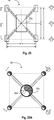
- the structural concept 10 of the present disclosure consists of a series of structural bays 12.
- the bays 12 have a spider-like configuration where a central connection 30 supports a number of structural braces (upper 40 and lower 50) that frame out from the central connection 30 to connect to the foundation piles 2 or other structural element (depending on the configuration) of the structure 12.
- the bays 12 may be made of structural steel, aluminum other metals, fiber reinforced composites, lightweight cementitious or other structural materials.
- Applications of the technology include support of offshore structures for oil and gas exploration and production and for generation of wind energy or other alternative energy sources.
- the technology is equally applicable to support of elevated facilities and equipment in the onshore environment.
- the design is also applicable as the truss component of floating structures e.g. Truss Spars.
- Figure 1A shows a schematic depiction of a conventional offshore oil and gas platform known in the art. Between the platform deck and the sea floor is a conventional structural jacket as is known in the art.
- Figure 1B illustrates a typical conventional offshore oil and gas platform jacket.
- Figure 2A provides an illustration where, with reference to the conventional platform depicted in Figure 1A , a new jacket template structure 10 is depicted.
- an exemplary platform structure 1 (here, an offshore oil and gas platform) employing the new jacket template structure 10 according to one embodiment of the present disclosure.
- the jacket template structure 10 supports the platform topsides section 3 above the waterline (WL), and extends downward to the seabed (SB) where it is secured into the seabed foundation 4.
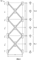
- the jacket template 10 comprises one or more vertical bay modules 12 attached together in stacked fashion to achieve the desired jacket height 11c.
- three bay units 12 are employed, but as will be appreciated by those having the benefit of this disclosure, the jacket template structure 10 can be configured in many different ways employing one or more bay units 12, and, as described below, the configuration of each bay unit 12 can be customized.
- each bay unit 12 comprises a central core member 30, two or more upper arms or braces 40 extending upwardly and outwardly from the core 30 to a desired length(s) 43, and two or more lower arms or braces 50 downwardly and outwardly from the core 30 at a desired length(s) 53.
- the length of the arms 40, 50 and angle of the arms 60, 63 will determine the overall height 14 of each bay unit.
- the end of each upper arm or brace 40 comprises a structural can device 20 for receiving a pile 2 therethrough (via interior channel 23).
- the end of each lower arm or brace 50 comprises a structural can device 70 for receiving a pile 2 therethrough (via interior channel 73).
- the piles 2 run generally vertically (or in battered slope) from the top 11a of the jacket 10 through each of the cans 20, 70 aligned with such pile, to the bottom of the jacket 11b where the piles can be secured into the seabed (SB).
- the desired platform topside section 3 (e.g., here depicted as an oil and gas platform deck and rig, etc.) is secured to the top end 11a of the jacket template using conventional techniques. Piles extend through the interior channels 23, 73 of cans 20, 70 on the jacket template and are secured into the seabed foundation 4.
- each face of the jacket template 10a is sloped (battered).
- the jacket 10a has an upper end 11a and a lower end 11b defining an overall jacket height 11c.
- this particular embodiment employs three four-legged battered bay modules 12 joined together to form a unitary structure 10a. As shown, the upper and lower cans 20 of each bay 12 are aligned about a can/pile axis 24.
- Each bay unit 12 comprises a different size to create the battered faces (here, in this embodiment, generally resembling a truncated pyramid or trapezoidal prism shape).
- the upper most upper arms 40c will likely have a shorter length 43 than the length of the lower most upper arms 40b, 40a to provide the battering face, however, the battering face can also be created by altering the angles of the arms.
- the upper most lower arms 50c will likely have a shorter length 43 than the length of the lower most lower arms 50b, 50a, but such battering face can also be achieved by altering the arm angle.
- This three level jacket template can be preassembled such that the lower cans 70 of one bay 12 are joined to the upper cans 40 of the bay 12 immediately underneath.
- the central bay support member or core 30 of each stacked bay are aligned about a bay central vertical axis 13.
- the bay central core members 30 can be solid or can be tubular (i.e., having an apertured opening running therethrough along the vertical axis 13.
- each bay module 12 can be varied by, e.g., varying the lengths of the arms 40, 50 and their respective upward or downward angles 60, 63, respectively. Such flexibility also permits creating battered or unbuttered faces where, e.g., the bay structure has no battering (straight vertical sides), partial battering, or full battering (double battering).
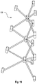
- Figure 3A shows an exemplary 4-legged (4-pile) style, double battered (vertical), structural bay unit module 12a.
- Figure 3B shows an exemplary 4-legged (4-pile) style, non-battered (vertical), structural bay unit module 12b.
- Figures 4 , 4A and 4B show additional views of the nonbattered bay depicted in Figure 3B .
- the vertical bay unit 12a, 12b comprises a central core support member 30 having a lower end 31 and an upper end 32 defining a length (L C ) 35.
- the core member 30 may be tubular with an internal open annulus or channel 33 of a desired diameter (D A ) 34 and having a vertical axis 13, or can be of a solid construction, e.g. block, round stock, I-beam, etc.
- Three or more upper structural braces 40 (of desired length 43) are attached (via known techniques, such as welding, molding, threading and the like) to the core 30 at the upper brace bottom ends 41 and extend outwardly and upwardly from the core 30 a desired length 43 to the upper brace upper end 42.
- the upper braces 40 extend upwardly from the core 30 at a desired upward angle ( ⁇ u ) 60 (relative to horizontal).
- Each bay upper structural brace 40 is preferably equally (radially) spaced apart about the vertical axis 13 from the adjacent braces 40 at a desired horizontal spacing angle ( ⁇ h ) 62. Other spacing arrangements are possible.
- the upper braces 40 attach to the core 30 at their bottom ends 41 and extend a desired length 43 to their upper ends 42.
- a tubular upper can 20 is attached by known techniques.
- the tubular upper cans 20 comprise upper can bottom edge 21, upper can top edge 22, and upper can interior channel or annular space 23 having a can interior diameter 25.
- the cans 20 are capable of receiving a pile 2 (not shown) therethrough (via annular space 33).
- three or more lower structural braces 50 (of desired length 53) are attached (via known techniques, such as welding, molding, threading and the like) to the core 30 at the lower brace upper ends 51 and extend outwardly and downwardly from the core 30 a desired length 53 to the lower brace lower end 52.
- the lower braces 50 extend downwardly from the core 30 at a desired downward angle ( ⁇ d ) 63 (relative to horizontal).
- Each bay lower structural brace 50 is preferably equally (radially) spaced apart about the vertical axis 13 from the adjacent braces 50 at a desired horizontal spacing angle ( ⁇ h ) 64. Other spacing arrangements are possible.
- the lower braces 50 attach to the core 30 at their top ends 51 and extend a desired length 53 to their lower ends 52.
- a tubular lower can 70 (similar to upper can 20) is attached by known techniques.
- the tubular lower cans 70 comprise lower can bottom edge 71, lower can top edge 72, and lower can interior channel or annular space 73 having a can interior diameter 25.
- the cans 70 are capable of receiving a pile 2 (not shown) therethrough (via annular space 73).
- the upper and lower cans 20, 70 can be mounted to the respective support arm ends 42, 52 and be oriented at the appropriate can angle ( ⁇ c ) 62, 65 to align the respective can interior channels 23, 73 along a desired can/pile axis 24.
- the bay 12b is a double battered shape resulting in the pile axis 24b being angled at a downward and outward slope relative to the ground (seafloor).
- Each of the respective upper and lower cans 20, 70 (can sets) is aligned about its respective can axis 24b.
- can axis 24b is not parallel to central core axis 13.
- the bay 12s is a non-battered configuration where the can sets (20, 70) align with each other in a substantially vertical orientation along can axis 24a.
- can axis 24a is substantially parallel to central core axis 13.
- the bay top half 14a and bay bottom half 14b are depicted as being mirror images of each other, with each top can 20 being aligned along the same axis 24a or 24b as its counterpart lower can 70.
- the a desired horizontal spacing angles ( ⁇ hl ) 64 between the lower arms 50 and the desired horizontal spacing angles ( ⁇ hu ) 61 between the upper arms is 90°. It is therefore preferred that the upper arms 40 be equally radially spaced apart from each other about the central core axis 13. Similarly, it is therefore preferred that the lower arms 50 be equally radially spaced apart from each other about the central core axis 13.
- These horizontal angles ( ⁇ hl,, ⁇ hu ) could be varied on the top half 14a and correspondingly on the bottom half 14b.
- the bays 12 can be extended or shortened in overall height 14 by adjusting the angle of the brace incidence at the central connection 30.
- the height 14 can be divided into the upper arm section height 14a and the lower arm section height 14b, and overall height adjustment can be achieved by altering the upper arm section height 14a and/or the lower arm section height 14b.
- the overall bay width 15 (divided into a left width 15a and right width 15b), can be varied by altering the right width 15a and/or the left width 15b (or via adjustment of the heights 14a, 14b).
- FIGS 3A , 3B , 4 , 4A and 4B depict the upper bay half comprising four upper arms 40 and four lower arms 50 (collectively referred to as a four legged or four pile style structure)
- the number of arms used can vary from three e.g., ( Figures 17A, 17B , 18 , 19 (three legged style bay)) to eight or more.
- Figures 17A, 17B , 18 , 19 three legged style bay
- increasing the number of arms that extend from the central core 30 will decrease the openings between equally spaced arms and increase the weight of the bay.
- the bay module 12 can be modified to include more than one central core within the same horizontal plane. See discussion below regarding, e.g., Figures 20 and 21 .
- Two or more bays may be stacked to further increase the height of the structure. This can be done either at the time of construction (e.g., the jacket templates illustrated in Figures 5 and 15 , 16 , 18 , 19 , 20 , 21 , 22 are shown in completed construction and could be prefabricated onshore and then transported to the desired location) or during the installation of the structure at its final or interim location, e.g., the jacket template 10b illustrated in Figure 7 illustrates how multiple separate bay units 12b could be connected together to form a non-battered jacket template such as shown in Figure 5.
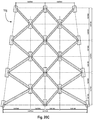
- Figure 5 illustrates a single-lift, vertically oriented prefabricated 4-legged style jacket template structure 10b constructed of multiple, stacked bay units 12b, such as the bay unit module in Figure 3B .
- FIGS 6 , 6A and 6B show additional views of the non-battered bay depicted in Figure 5 .
- Each of the vertically stacked bays constitutes a separate tier, e.g., Tier 1, Tier 2, Tier 3, and each tier lies in a separate horizontal plane.
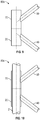
- connection detail such as 80, 80a, 80b, 80c is necessary.
- the connection detail may include any number of structural connections, such as, for example and without limitation: a castellated weld; a threaded (sleeve); a sleeve (welded); a grouted connection 80c (see Figure 10 ) with or without beads; a full or part penetration weld; a 1-piece member extending through the central can; a swaged or force fit connection type; a bolted flange connection 80a (see Figures 8 and 8A ); a Zap-Lok style telescoping interconnection 80b (see Figure 9 ); epoxy / glue; and pre-drilled holes in central can that members can fit into (possibly threaded).
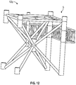
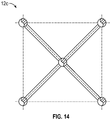
- FIG. 11-14 there is depicted a non-battered, four legged jacket template 10c, much like that illustrated in Figure 5 where the topmost bay 12c is configured with various additional structural features, such as boat landings
- Bays may be connected in a multitude of patterns to develop large structures that will accommodate anywhere from three to an unlimited number of foundation piles.
- FIGs 15 and 15A there is shown a double battered jacket template section 10a, similar to that in Figure 2C , and also similar to the non-battered jacket template section 10b of Figure 5 .
- Figures 16 , 16A and 16B illustrate a 4-legged style jacket template structure 10c constructed of multiple, stacked bay units employing battered and non-battered (vertical) faces.
- Figure 17A illustrates a three legged style, non-battered (vertical), single structural bay unit 12d
- Figure 17B illustrates a three legged battered (vertical), single structural bay unit 12e
- Figure 18 illustrates a vertically oriented 3-legged style non-battered (vertical) jacket template structure 10e constructed of multiple, stacked bay units (such as shown in Figure 17A
- Figure 19 illustrates a vertically oriented 3-legged style battered (vertical) jacket template structure 10f constructed of multiple, stacked bay units (such as shown in Figure 17B .
- the bay module 12 can be modified to include more than one central core within the same horizontal plane.
- Figures 20 , 20A , 20B and 20C illustrate a multi-tiered (here, three-tiered) jacket template 10g where, within each tier, two, four legged bay units have been combined together in side-by-side fashion so that they share two of the upper and lower cans, 20a, 70a.
- the jacket template 10g has six legs to accommodate 6 piers, and uses two central core units 30a disposed within the same horizontal plane.
- Each set of stacked bays constitutes a separate tier (Tier 1, Tier 2, Tier 3), and each tier lies in a separate horizontal plane.
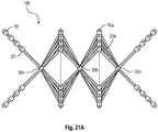
- FIG. 21 , 21A , 21B , and 21C there is shown a vertically oriented 8-legged style double battered jacket template structure 10h constructed of multiple, stacked bay units.
- three standard four-legged bay units are joined together horizontally (sharing the cans between adjacent bay units) to form each of the stacked rows.
- the jacket template 10g has eight legs to accommodate 8 piers, and uses three central core units 30b disposed within the same horizontal plane.
- the legs may be replaced by buoyancy tanks used for the self-installation of the structure.
- the system may also be installed by controlled launch from a barge or lifting with a crane, floating and upending or floating on a suction foundation system. When the individual bays are installed onsite, a smaller crane can be employed than that required if lifting a preassembled jacket template.
- the structure can be fixed to the ground (sea floor) with conventional vertical or raked piles or with an alternative foundation such as a gravity base or suction pile(s). Mud mats may be required to provide on-bottom stability during installation.
- a vertically oriented, battered jacket template structure 10i constructed of multiple, stacked bay units having battered faces and also employing skirt piles 6.
- bays may be optimized to create additional space.
- Structural framing may be added to make each 'triangular area' (seen in plan-view of the bay) a full square to provide larger internal space.
- Variations of the central core connections 30 may exist to provide a larger central conduit 30a through the structure where this may be beneficial to the design, e.g., passage of pipeline risers, umbilicals, production or injection wells, power cables or other appurtenances to the facility requiring structural support and/or protection.
- a non-battered, 4 legged bay module similar to that in Figure 3B employing a larger core structural member 30a.
- the core 30 may be tubular with a large internal diameter 34a to permit, for example, ingress and egress of equipment.
- the central connection system 30, 30a may therefore comprise, for example: various shapes and sizes of hollow or stiffened cans; multiple connected cans; a multisided framed structure; or other connection type.
- the system of the present disclosure is designed to provide a modular bay design and jacket template design that is low mass, high ductility, lightweight, ideal seismic performance qualities, and flexible for use on land and offshore.
- the capability of having multi-piece construction of the template jacket, for e.g., construction of an offshore oil and gas platform permits the use of smaller crane units (that have significantly lower day rates than the larger cranes) which in turn provides cost/weight savings.
- the variability of the angles and arm lengths on the modules provides great flexibility in designing the overall height of the jacket template required at the place of installation, e.g., based on the water depth for an offshore installation.
- the new jacket template structure disclosed herein has many applications as will be appreciated by those having the benefit of the present disclosure.
- the new jacket template design can be used for the installation of offshore wind turbines.
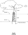
- FIG 26 there is shown a schematic depiction of a conventional offshore wind turbine installation known in the art where the jacket bracing also serves to stabilize a submerged portion of the turbine tower. Between the topside section and the sea floor is a conventional structural jacket used for installation of offshore wind turbines as is known in the art.
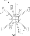
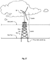
- Figure 27 provides an illustration where, with reference to the conventional wind turbine depicted in Figure 26 , a new jacket template structure 10j is depicted.
- the central core 30a of one or more of the vertically aligned bays can be designed to have a large inner diameter 34a and enhanced height 35a to accommodate and secure to the outer diameter of the tower section 91 of the wind turbine.
- the core members 30a extend and are attached to each other to create an extended vertical tubular structure extending between two vertically adjacent bay members. This extended tubular core member (not shown) could be employed in any of the jacket designs described herein, including being employed to receive a lower portion of a wind turbine tower section.
- associated energy transmission platforms could likewise employ the new jacket template design described herein.
- Typical jacket construction (of the prior art types disclosed in Figs. 1A and 1B ), requires manufacturing and assembly onshore at a facility that is close to the point of installation since the actual template structure it too large to transport over land.
- off-shore template jacket structures of the prior art they require manufacture and assembly on shore at a coastal location so that the completed template jacket can be floated (or barged) to the offshore location.
- This time, complexity and cost becomes magnified when it is desired to install an elaborate field of jacket template structures, such as with an offshore wind farm where there may be tens if not hundreds of jacket templates required.
- the structural building jacket designs described herein provide great flexibility, cost savings and time savings when it comes to designing, manufacturing, assembling and installing the jackets.
- the structural building jacket designs comprise a low number of basic building block component parts (e.g., tubular steel nodes) used to assemble the jacket, e.g., upper and lower tubular nodes (20, 70), central bay support nodes (30), and connecting structural braces (40, 50).
- basic building block component parts e.g., tubular steel nodes
- Other ancillary parts such as boat landings (5), skirt piles (6), and pilings are readily available.
- these primarily tubular steel (or other suitable material) building block component parts can be produced at any convenient location, and can be mass-produced.
- Mass production/rapid production of these component parts becomes particularly important where there exists a planned installation of multiple jacket structures, e.g., for an extensive offshore windfarm installation comprising many separate jacket structures, such wind farms including arrays of tens if not hundreds of wind turbines each mounted on a separate jacket template.
- component parts capable of mass production, they can be manufactured using known manufacturing techniques, such as forgings, castings, robotics, automated welding, use of high quality indoor fabrication/manufacturing facilities. It is also envisioned that these component parts are susceptible to manufacture using 3D printing (a.k.a. Direct Digital Manufacturing) technologies.
- 3D printing technology is the Electron Beam Additive Manufacturing (EBAMTM) technology offered by Sciaky Inc. (Chicago, Ill)(www.sciaky.com) under the brand names EBAMTM 300, EBAMTM 1500, EBAMTM 110, EBAMTM 88, and EBAMTM 68.
- EBAMTM Electron Beam Additive Manufacturing
- the EBAM system is a 3D printing technology that is capable of producing high quality, high value, large-scale metal parts and structures (e.g., up to 19 feet in length), out of, e.g., titanium, tantalum, and nickel-based alloys in a matter of days, with very little material waste.
- These systems all combine computer-aided design (CAD), electron beam directed energy deposition, and layer-additive processing.
- CAD computer-aided design
- EBAM electron beam (EB) gun deposits metal (via wire feedstock), layer by layer, until the part reaches near-net shape and is ready for finish machining.
- the Sciaky EBAM system also employs the IRISSTM (Interlayer Realtime Imaging & Sensing System), a patented closed-loop control that provides consistent part geometry, mechanical properties, microstructure, metal chemistry over the course of operation. Gross deposition rates range from 7 to 20 lbs. (3.18 to 9.07 kg) of metal per hour, depending upon the selected material and part features.
- IRISSTM Interlayer Realtime Imaging & Sensing System
- an EBAM dual wirefeed system one can combine two different metal alloys into a single melt pool, managed with independent program control, to create "custom alloy” parts or ingots.
- One also has the option to change the mixture ratio of the two materials, depending upon the features of the part that you are building, to create "graded” parts or structures.
- one can alternate between different wire gauges for finer deposition features (thin wire) and gross deposition features (thick wire). These benefits may be provided by the Sciaky, Inc. EBAMTM dual wirefeed process.
- Titanium and Titanium alloys include: Titanium and Titanium alloys; Inconel 718, 625; Tantalum; Tungsten; Niobium; Stainless Steels (300 series); 2319, 4043 Aluminum; 4340 Steel; Zircalloy; 70-30 Copper Nickel; and 70-30 Nickel Copper.
- the EBAM system's dual wirefeed process allows one to combine two different metal alloys into a single melt pool to create "custom alloy” parts or “graded” material parts, as well as switch between fine (thin wire) deposition features and gross (thick wire) deposition features.
- the Sciaky EBAMTM system works with refractory alloys and it produces significantly less material waste - plus, wire feedstock is not highly flammable like some powder feedstocks.
- a non-extensive listing includes: the VX4000 sand casting process by Voxeljet AG (Friedberg, Germany); the Objet 1000 polyjet process by Statasys Ltd. (Eden Prairie, MN); the Lens 850-R laser process by Optomec Inc. (Albuquerque, NM); the Project 5000 multijet printing process by 3D Systems Corporation (Rock Hill, SC); the M400 laser process by EOS Gmbh (Munich, Germany); and the Arcam Q20 electron beam melting process by Arcam AB (Mölndal, Sweden).
- 3D printing technologies are thought to be well-suited for use in the rapid, cost effective manufacturing of the component parts for the jacket designs disclosed herein.
- a 3D printing facility could be located proximate the point of final assembly of the jacket (such as, for example, near a seaport where jackets are being assembled onshore for transport and installation offshore).
- a mobile unit such as one that could be taken offshore to print component parts "on site” as needed for the desired jacket assembly.
- the raw materials would likewise be transported offshore so that the mobile offshore 3D printing facility could manufacture the jacket component parts on an as needed basis.
- the component parts for the template jackets can be mass produced in any location, and then shipped by conventional means to a desired location for final assembly of the jacket structures.
- the jacket component parts could be manufactured in the same location as for the final assembly.
- Such final assembly can be onshore (with the final templates then floated, barged or otherwise transported to the offshore location) or the component parts can be delivered to the offshore location for final assembly offshore.
- the entire jacket manufacturing and assembly process could be offshore.
- the jacket templates themselves are of a lower overall weight than a traditional prior art jacket template; therefore, this alone provides cost savings in connection with the material, manufacturing, assembly and transport costs. Additionally, mass production of the parts, 3D printing of the parts, etc., lowers waste, improves fatigue performance and increases environmental protection.
- the jacket structures of the present disclosure also provide for faster, more cost effective installation than with traditional jacket structures.
- installation requires use of a heavy weight certified lifting crane vessel to pick up the heavy jacket structure and place it on the surface to be installed (e.g., seabed for offshore installation), and to then install all of the permanent piles (e.g., driving multiple piles into the seabed) to secure the prior art jacket in place.
- This occupies the use of this heavy lifting crane, which itself carries a much higher day rate cost to operate than a lighter weight crane vessel, for the duration of the jacket installation process thereby increasing day rate costs.
- a low cost pile driving vessel can first install into, e.g., the seabed, a first location pile (using standard pile driving techniques). This pre-installed location pile will be installed at a pre-determined desired location (using a low day rate pile driving vessel), and will serve as one of the, e.g., four permanent piles used to secure the jacket in place (e.g., to the seabed).
- the crane can then be used to install the pre-assembled jacket template over the pre-installation permanent pile, for example, by lowering the jacket template with can sets (20, 70) and can axis 24a aligned with the preinstalled location pile.
- the jacket template design permits the jacket template to remain stable and in place over this single location pile until a separate, lower day rate pile driving vessel completes the securing of the jacket to, e.g., the seabed by driving in the remaining, e.g., 3 of 4 permanent piles. Therefore, the more expensive day rate lifting crane vessel, after lowering the jacket template over the initial location pile can then be freed up to efficiently perform other crane work, such as installing yet another jacket template on yet another nearby pre-installed location pile.
- This installation process is particularly cost effective when a large number of jacket templates must be installed, e.g., in an offshore wind farm.
- a series of location piles would be installed ahead of the time when the heavy crane would be used to lower the jacket templates into place.
- This series of location piles would be installed by, e.g., a routine pile driving vessel.
- the heavy crane vessel could then be efficiently used to lower a first jacket over a first location pile, then move to the next location to lower a second jacket over a second location pile, etc., until all such jackets were placed over the applicable location piles.
- a separate pile driving vessel is used, following behind the lifting crane, to complete the installation of all permanent piles on each jacket.
- logistical planning would account for anticipated weather conditions so that the follow-on pile driving vessel's work would be completed for each jacket previously lowered in place by the crane vessel prior to any weather conditions arising that could potentially adversely impact a jacket that had not yet been fully secured with all permanent piles.
- the new jacket template design of the present disclosure provides cost savings in terms of material, manufacturing time, assembly time, and vessel/crane day rate and time.
- the new jacket template design 10 disclosed herein offers a number of benefits and efficiencies through its service life and extending into its eventual decommissioning and either re-use or disposal.
- In-Service Inspection/Repair Unlike a conventional, prior art jacket structure, the 3-dimensional nature of the jacket framing design disclosed herein allows access by un-manned inspection tools referred to as Remotely Operated Vehicles (ROVs) or Autonomous Un-manned Vehicles (AUV).
- ROVs Remotely Operated Vehicles
- AUV Autonomous Un-manned Vehicles
- the underwater vehicles can access all the structural connections (joints) in the jacket framing for the purposes of critical in-service inspection as part of the life-cycle integrity management of the structure. This is not normally possible in a conventional jacket as the ROV or AUV is at serious risk of entanglement within the confines of the 2-dimensional framing walls of the jacket.
- the modular, open structure also lends itself to easier in-service repairs.
- Decommissioning/Reuse At the end of life of the jacket structures disclosed herein, the very same features that made the installation of the jacket so efficient also contribute to the ease of its removal.
- the lighter weight opens up the market for smaller lift vessels.
- the avoidance of grouting or any other underwater connections allows for safer and more rapid removal of the structure.
- the ability to cut the piles below mudline with internal cutting tools allows for the efficient removal of the piles and the jacket structure itself, making reuse of the facility (jacket structure) at another location a real and attractive possibility.
- novel jacket structures disclosed herein provide advantages during the entire lifecycle of this type of structure: at the manufacturing stages, during the installation stages, during its intended use, during inspections of the structure throughout the duration of its intended use, during removal of the structure for decommissioning or reuse.
Claims (15)
- Vertikal orientiertes strukturelles Gebäudemodul (12), das zum Stapeln mit einem oder mehreren anderen strukturellen Gebäudemodulen desselben Typs konfiguriert ist, wobei das strukturelle Gebäudemodul (12) Folgendes umfasst:a. ein zentrales Kernelement (30), das entlang einer zentralen vertikalen Kernachse (13) ausgerichtet ist, wobei die Kernstruktur (30) ein oberes Ende (32), ein unteres Ende (31) und eine Außenfläche aufweist;b. drei oder mehr obere Strukturarme (40) jeweils mit einem unteren (41) und einem oberen Ende (42), die eine obere Armlänge (43) definieren, wobei die unteren Enden (41) der oberen Arme (40) an der Kernaußenfläche in radial beabstandeter Beziehung um die vertikale Achse (13) herum fixierbar angebracht sind, wobei sich jeder obere Arm (40) vom Kern (30) nach außen und nach oben in seiner eigenen vertikalen Ebene in einem gewünschten Winkel θu relativ zur Horizontalen (60) erstreckt;c. drei oder mehr untere Strukturarme (50) jeweils mit einem unteren (52) und einem oberen (51) Ende, die eine untere Armlänge (53) definieren, wobei die oberen Enden (51) der unteren Arme (50) an der Kernaußenfläche in radial beabstandeter Beziehung um die vertikale Achse (13) herum fixierbar angebracht sind, wobei sich jeder untere Arm (50) vom Kern (30) in einem gewünschten Winkel θd relativ zur Horizontalen (63) nach außen und nach unten erstreckt;d. obere röhrenförmige Dosen (20), die an den oberen Enden (42) der oberen Arme (40) angebracht sind, wobei die oberen röhrenförmigen Dosen (20) jeweils eine Außenfläche, einen ringförmigen Innenraum (23), der um eine Dosenachse (24) ausgerichtet ist und einen Innendurchmesser (25) aufweist, und eine Dosenlänge definierende obere (22) und untere (21) Enden aufweisen, wobei jede der oberen röhrenförmigen Dosen (20) an den oberen Armen (40) in einer im Wesentlichen vertikalen Orientierung angebracht ist, um den ringförmigen Innenraum (23) jeder der Dosen (20) in einem gewünschten Dosenwinkel θc relativ zur Horizontalen auszurichten; unde. untere röhrenförmige Dosen (70), die an den unteren Enden (52) der unteren Arme (50) angebracht sind, wobei die unteren röhrenförmigen Dosen (70) jeweils eine Außenfläche, einen ringförmigen Innenraum (23), der um eine Dosenachse (24) herum orientiert ist und einen Innendurchmesser (25) aufweist, und eine Dosenlänge definierende obere (72) und untere (71) Enden aufweisen, wobei jede der unteren röhrenförmigen Dosen (70) an den unteren Armen (50) in einer im Wesentlichen vertikalen Orientierung angebracht ist, um den ringförmigen Innenraum (23) jeder der Dosen (70) in einem gewünschten Dosenwinkel θc relativ zur Horizontalen auszurichten;wobei alle jeweiligen oberen Arme (40) innerhalb derselben vertikalen Ebene mit einem entsprechenden der jeweiligen unteren Arme (50) ausgerichtet sind, um ein oberes unteres Armpaar zu bilden;
wobei die oberen (20) und unteren (70) Dosen jedes der jeweiligen Armpaare um dieselbe Dosenachse (24) herum ausgerichtet ist, um eine Armpaar-Dosenachse (24) zu bilden;
wobei die oberen röhrenförmigen Dosen (20) zum Verbinden mit unteren röhrenförmigen Dosen eines oder mehrerer anderer struktureller Gebäudemodule desselben Typs konfiguriert sind; und
wobei die unteren röhrenförmigen Dosen (70) zum Verbinden mit oberen röhrenförmigen Dosen eines oder mehrerer anderer struktureller Gebäudemodule desselben Typs konfiguriert sind. - Gebäudemodul (12) von Anspruch 1, wobei:a. mindestens eine Armpaar-Dosenachse (24) im Wesentlichen parallel zur vertikalen Kernachse (13) ist; oderb. mindestens eine Armpaar-Dosenachse (24) im Wesentlichen vertikal ist; oderc. jede Armpaar-Dosenachse (24) im Wesentlichen vertikal ist; oderd. es drei obere Strukturarme (40) und drei untere Strukturarme (50) gibt; odere. es vier obere Strukturarme (40) und vier untere Strukturarme (50) gibt; oderf. es fünf obere Strukturarme (40) und fünf untere Strukturarme (50) gibt; oderg. es sechs obere Strukturarme (40) und sechs untere Strukturarme (50) gibt; oderh. die Kernstruktur (30) massiv ist; oderi. die Kernstruktur (30) ferner einen ringförmigen Innenraum (33) mit einem Innendurchmesser (34) aufweist; wobei die Kernstruktur (30) optional ein röhrenförmiges Material umfasst; oderj. die oberen Arme (40) alle gleich lang sind; oderk. die unteren Arme (50) alle gleich lang sind; oderl. mindestens einer der oberen Arme (40) eine andere Länge hat als die anderen oberen Arme (40), oderm. mindestens einer der unteren Arme (50) eine andere Länge hat als die anderen unteren Arme (50).
- Gebäudemodul (12) nach Anspruch 1, das ferner zwei oder mehr benachbarte zentrale Kernelemente (30, 30a) umfasst, die innerhalb derselben horizontalen Ebene horizontal voneinander beabstandet sind, so dass ein benachbartes Kernelement (30, 30a) eine benachbarte Fläche aufweist, die einer benachbarten Fläche eines anderen benachbarten Kernelements (30, 30a) zugewandt ist;
wobei die oberen röhrenförmigen Dosen (20, 20a) von zwei der oberen Arme (40), die sich von einer der benachbarten Flächen des Kernelements nach oben erstrecken, mit den jeweiligen oberen Enden (42) von zwei der oberen Arme (40) verbunden sind, die sich von der benachbarten Fläche des anderen Kernelements (30, 30a) nach oben erstrecken, so dass diese sich nach oben erstreckenden Arme (40) obere röhrenförmige Dosen (20, 20a) gemeinsam haben,
wobei die unteren röhrenförmigen Dosen (70, 70a) von zwei der unteren Arme (50), die sich von einer der benachbarten Flächen des Kernelements nach unten erstrecken, mit den jeweiligen unteren Enden (52) von zwei der unteren Arme (50) verbunden sind, die sich von der benachbarten Fläche des anderen Kernelements (30, 30a) nach unten erstrecken, so dass diese sich nach unten erstreckenden Arme (50) untere röhrenförmige Dosen (70, 70a) gemeinsam haben, und
wobei die oberen Arme (40), die obere röhrenförmige Dosen (20, 20a) gemeinsam haben, mit den unteren Armen (50) ausgerichtet sind, die untere röhrenförmige Dosen (70, 70a) gemeinsam haben, und
wobei alle jeweiligen oberen Arme (40), die obere röhrenförmige Dosen (20, 20a) gemeinsam haben, in derselben vertikalen Ebene mit einem entsprechenden der jeweiligen unteren Arme (50) ausgerichtet sind, die untere röhrenförmige Dosen (70, 70a) gemeinsam haben, um ein gemeinsames oberes unteres Armpaar zu bilden. - Mehrstufige, vertikal orientierte strukturelle Gebäudemantelschablone (10) zum Aufbauen einer vertikalen Struktur, die Folgendes umfasst:a. ein vertikal orientiertes strukturelles Gebäudemodul (12) der unteren Stufe nach Anspruch 1 mit einem unteren Ende, das auf einem Fundament (3) ruhen kann, und einem diesem gegenüberliegenden oberen Ende,b. ein oder mehrere vertikal orientierte strukturelle Gebäudemodule (12) der oberen Stufe nach Anspruch 1 jeweils mit einem unteren Ende und einem oberen Ende, wobei das untere Ende eines ersten der ein oder mehreren Module (12) der oberen Stufe am oberen Ende der unteren Stufe fixierbar angebracht ist, wobei das untere Ende jedes zusätzlichen der ein oder mehreren Module (12) der oberen Stufe fixierbar am oberen Ende des Moduls (12) in der unmittelbar darunter liegenden Stufe angebracht ist;c. Verbindungen (80), die die unteren Dosen (70) des unteren Endes des ersten der ein oder mehreren Module (12) der oberen Stufe mit den oberen Dosen (20) der unteren Stufe verbinden; undd. Verbindungen (80), die das untere Ende jedes zusätzlichen der ein oder mehreren Module (12) der oberen Stufe mit dem oberen Ende des Moduls (12) in der unmittelbar darunter liegenden Stufe verbinden;e. eine Gesamthöhe (11c), definiert als der Abstand vom Boden der unteren Stufe (11b) zur Oberseite der obersten der oberen Stufen (11a);wobei die obere (20) und untere (70) Dose jeder der jeweils angebrachten Modulstufen (12) um die gleiche jeweilige Dosenachse (24) von der Oberseite der Mantelschablone (11a) bis zur Unterseite der Mantelschablone (11b) ausgerichtet bleiben, und
wobei die zentralen Kernelemente (30) in jeder der Modulstufen (12) entlang der zentralen vertikalen Kernachse (13) ausgerichtet bleiben. - Strukturelle Gebäudemantelschablone (10) nach Anspruch 4, die zwei, drei oder vier Stufen umfasst.
- Strukturelle Gebäudemantelschablone (10) nach Anspruch 4, wobei:a. die Oberseite der obersten Stufe eine Deckstruktur (3) aufnehmen kann;b. der Innendurchmesser der Dosen (25) ausreicht, um den Durchgang eines Pfahls (2) durch sie zu ermöglichen; oderc. das Fundament (4) der Meeresboden, der Boden, eine Betonplatte oder eine andere Struktur ist.
- Strukturelle Gebäudemantelschablone (10) nach Anspruch 4, wobei das Gebäudemodul (12) ferner zwei oder mehr benachbarte zentrale Kernelemente (30, 30a) aufweist, die innerhalb derselben horizontalen Ebene horizontal voneinander beabstandet sind, so dass ein benachbartes Kernelement (30, 30a) eine benachbarte Fläche hat, die einer benachbarten Fläche eines anderen benachbarten Kernelements (30, 30a) zugewandt ist;
wobei die oberen röhrenförmigen Dosen (20, 20a) von zwei der oberen Arme (40), die sich von einer der benachbarten Kernelementflächen nach oben erstrecken, mit den jeweiligen oberen Enden (42) von zwei der oberen Arme (40) verbunden sind, die sich von der benachbarten Fläche des anderen Kernelements (30, 30a) nach oben erstrecken, so dass diese sich nach oben erstreckenden Arme (40) obere röhrenförmige Dosen (20, 20a) gemeinsam haben,
wobei die unteren röhrenförmigen Dosen (70, 70a) von zwei der unteren Arme (50), die sich von einer der benachbarten Kernelementflächen nach unten erstrecken, mit den jeweiligen unteren Enden (52) von zwei der unteren Arme (50) verbunden sind, die sich von der benachbarten Fläche des anderen Kernelements (30, 30a) nach unten erstrecken, so dass diese sich nach unten erstreckenden Arme (50) untere röhrenförmige Dosen (70, 70a) gemeinsam haben, und
wobei die oberen Arme (40), die obere röhrenförmige Dosen (20, 20a) gemeinsam haben, mit den unteren Armen (50) ausgerichtet sind, die untere röhrenförmige Dosen (70, 70a) gemeinsam haben, und
wobei alle jeweiligen oberen Arme (40), die obere röhrenförmige Dosen (20, 20a) gemeinsam haben, in derselben vertikalen Ebene mit einem entsprechenden der jeweiligen unteren Arme (50) ausgerichtet sind, die untere röhrenförmige Dosen (70, 70a) gemeinsam haben, um ein gemeinsames oberes unteres Armpaar zu bilden. - Strukturelle Gebäudemantelschablone (10) nach Anspruch 4, wobei die vertikale Struktur eine Öl- und Gasplattform oder eine Windenergieplattform ist.
- Öl- und Gasplattform, die Folgendes umfasst:a. eine mehrstufige, vertikal orientierte strukturelle Gebäudemantelschablone (10) nach Anspruch 4 oder 7 mit einem oberen Ende (11a) und einem unteren Ende (11b), wobei das untere Ende an einem Fundament (4) befestigt ist;b. eine Deckstruktur (3), die am oberen Ende (11a) der Mantelschablone (10) montiert ist; undc. Pfähle (2), die sich durch den ringförmigen Innenraum (23) jeder der oberen (20) und unteren (70) röhrenförmigen Dosen erstrecken, die entlang der jeweiligen Dosenachse (24) ausgerichtet sind, wobei die Pfähle (2) ein oberes Ende und ein unteres Ende aufweisen, die eine Pfahllänge definieren, die ausreicht, um sich entlang jeder Dosenachse (24) vom oberen Ende der Mantelschablone (11a) bis zu einer gewünschten Tiefe in das Fundament (4) zu erstrecken.
- Windenergieplattform, die Folgendes umfasst:a. eine mehrstufige, vertikal orientierte strukturelle Gebäudemantelschablone (10) nach Anspruch 4 oder 7 mit einem oberen Ende (11a) und einem unteren Ende (11b), wobei das untere Ende an einem Fundament (4) befestigt ist;b. eine Deckstruktur (3), die am oberen Ende (11a) der Mantelschablone (10) befestigt ist; undc. Pfähle (2), die sich durch den ringförmigen Innenraum (23) jeder der oberen (20) und unteren (70) röhrenförmigen Dosen erstrecken, die entlang jeder jeweiligen Dosenachse (24) ausgerichtet sind, wobei die Pfähle (2) ein oberes Ende und ein unteres Ende aufweisen, die eine Pfahllänge definieren, die ausreicht, um sich entlang jeder Dosenachse (24) vom oberen Ende (11a) der Mantelschablone (10) bis zu einer gewünschten Tiefe in das Fundament (4) zu erstrecken.
- Öl- und Gasplattform nach Anspruch 9 oder Windenergieplattform nach Anspruch 10:(a) die ferner Schürzenpfähle umfasst;(b) wobei die Mantelschablone (10) verjüngt ist; oder(c) wobei die Mantelschablone (10) nicht verjüngt ist.
- Windenergieplattform nach Anspruch 10, wobei das zentrale Kernelement (30, 30a) des Gebäudemoduls (12) ferner ein röhrenförmiges Material mit einem ringförmigen Innenraum (33) mit einem Innendurchmesser (34, 34a) umfasst und wobei eines oder mehrere der vertikal ausgerichteten zentralen Kernelemente benachbarter Module (30, 30a) an der Oberseite des Mantels (11a) einen Abschnitt eines Turms einer Windturbine aufnehmen.
- Verfahren zum Installieren einer Plattformstruktur (3), das die folgenden Schritte beinhaltet:a. Zusammenbauen einer mehrstufigen, vertikal orientierten strukturellen Gebäudemantelschablonen-Vertikalstruktur (10) mit einem oberen Ende (11a) und einem unteren Ende (11b), das an einem Fundament (4) befestigt werden kann, wobei die vertikale Mantelschablonenstruktur (10) Folgendes umfasst:i. ein vertikal orientiertes strukturelles Gebäudemodul (12) der unteren Stufe mit einem unteren Ende, das auf einem Fundament (4) ruhen kann, und einem diesem gegenüberliegenden oberen Ende,ii. ein oder mehrere vertikal orientierte strukturelle Gebäudemodule (12) der oberen Stufe jeweils mit einem unteren Ende und einem oberen Ende, wobei das untere Ende eines ersten der ein oder mehreren Module (12) der oberen Stufe fixierbar am oberen Ende der unteren Stufe angebracht ist, wobei das untere Ende jedes zusätzlichen der ein oder mehreren Module (12) der oberen Stufe fixierbar am oberen Ende des Moduls (12) in der unmittelbar darunter liegenden Stufe verbunden ist;
wobei jedes vertikal orientierte strukturelle Gebäudemodul (12) Folgendes umfasst:1. ein zentrales Kernelement (30), das entlang einer zentralen vertikalen Kernachse (13) ausgerichtet ist, wobei die Kernstruktur (30) ein oberes Ende (32), ein unteres Ende (31) und eine Außenfläche aufweist;2. drei oder mehr obere Strukturarme (40) jeweils mit einem unteren (41) und einem oberen (42) Ende, die eine obere Armlänge (43) definieren, wobei die unteren Enden (41) der oberen Arme (40) fixierbar an der Kernaußenfläche in radial beabstandeter Beziehung um die vertikale Achse (13) herum angebracht sind, wobei jeder obere Arm (40) sich vom Kern (30) nach außen und nach oben in seiner eigenen vertikalen Ebene in einem gewünschten Winkel θu relativ zur Horizontalen (60) erstreckt;3. drei oder mehr untere Strukturarme (50) jeweils mit einem unteren (52) und einem oberen (51) Ende, die eine untere Armlänge (53) definieren, wobei die oberen Enden (51) der unteren Arme (50) fixierbar an der Kernaußenfläche in radial beabstandeter Beziehung um die vertikale Achse (13) herum angebracht sind, wobei sich jeder untere Arm (50) vom Kern (30) in einem gewünschten Winkel θd relativ zur Horizontalen (63) nach außen und unten erstreckt,4. obere röhrenförmige Dosen (20), die an den oberen Enden (42) der oberen Arme (40) angebracht sind, wobei die oberen röhrenförmigen Dosen (20) jeweils eine Außenfläche, einen ringförmigen Innenraum (23), der um eine Dosenachse (24) orientiert ist und einen Innendurchmesser (25) aufweist, und eine Dosenlänge definierende obere (22) und untere (21) Enden aufweisen, wobei jede der oberen röhrenförmigen Dosen (20) an den oberen Armen (40) in einer im Wesentlichen vertikalen Orientierung angebracht ist, um den ringförmigen Innenraum (23) jeder der Dosen (20) in einem gewünschten Dosenwinkel θc relativ zur Horizontalen auszurichten; und5. untere röhrenförmige Dosen (70), die an den unteren Enden (52) der unteren Arme (50) angebracht sind, wobei die unteren röhrenförmigen Dosen (70) jeweils eine Außenfläche, einen ringförmigen Innenraum (23), der um eine Dosenachse (24) herum orientiert ist und einen Innendurchmesser (25) aufweist, und eine Dosenlänge definierende obere (72) und untere (71) Enden aufweisen, wobei jede der unteren röhrenförmigen Dosen (70) an den unteren Armen (50) in einer im Wesentlichen vertikalen Orientierung angebracht ist, um den ringförmigen Innenraum (23) jeder der Dosen (70) in einem gewünschten Dosenwinkel θc relativ zur Horizontalen auszurichten,wobei alle jeweiligen oberen Arme (50) innerhalb derselben vertikalen Ebene mit einem entsprechenden der jeweiligen unteren Arme (40) ausgerichtet sind, um ein oberes unteres Armpaar zu bilden, und
wobei die obere (20) und die untere (70) Dose jedes der jeweiligen Armpaare um die gleiche Dosenachse (24) ausgerichtet wird, um eine Armpaar-Dosenachse (24) zu bilden;iii. Verbindungen (80), die die unteren Dosen (70) des unteren Endes des ersten der ein oder mehreren Module (12) der oberen Stufe mit den oberen Dosen (20) der unteren Stufe verbinden; undiv. Verbindungen (80), die das untere Ende jedes zusätzlichen der ein oder mehreren Module (12) der oberen Stufe mit dem oberen Ende des Moduls (12) in der unmittelbar darunter liegenden Stufe verbinden;v. eine Gesamthöhe (11c), definiert als der Abstand vom Boden der unteren Stufe (11b) zur Oberseite der obersten der oberen Stufen (11a);wobei die oberen (20) und unteren (70) Dosen jeder der jeweils angebrachten Modulstufen (12) um dieselbe jeweilige Dosenachse (24) von der Oberseite (11a) der Mantelschablone (10) bis zum Boden (11b) der Mantelschablone (10) ausgerichtet bleiben, und
wobei die zentralen Kernelemente (30) in jeder der Modulstufen (12) entlang der zentralen vertikalen Kernachse (13) ausgerichtet bleiben;b. vertikales Positionieren der Mantelschablonenstruktur (10), so dass ihr unteres Ende (11b) auf dem Fundament (4) ruht; undc. Befestigen der Mantelschablonenstruktur (10) am Fundament (4) durch Installieren von Pfählen (2), die sich durch den ringförmigen Innenraum (23) sowohl der oberen (20) als auch der unteren (70) röhrenförmigen Dosen erstrecken, die entlang jeder jeweiligen Dosenachse (24) ausgerichtet sind, wobei die Pfähle (2) ein oberes Ende und ein unteres Ende aufweisen, die eine Pfahllänge definieren, die ausreicht, um sich entlang jeder Dosenachse (24) vom oberen Ende der Mantelschablone (11a) bis zu einer gewünschten Tiefe in das Fundament (4) zu erstrecken. - Verfahren nach Anspruch 13, wobei die Mantelschablone (10) ferner eine Deckstruktur (3) aufweist, die am oberen Ende (11a) der Mantelschablone (10) angebracht ist, oder wobei das Verfahren ferner den Schritt des Montierens einer Deckstruktur (3) am oberen Ende (11a) der Mantelschablone (10) beinhaltet; das optional ferner Folgendes beinhaltet:a. die Schritte des Installierens von Ausrüstung für den Einsatz der Plattform (3) als Öl- und Gasplattform; wobei die Plattform (3) optional an einem Offshore-Ort in einem Gewässer mit einem Meeresspiegel und einem Meeresboden installiert wird, wobei die Deckstruktur (3) über dem Meeresspiegel angeordnet ist und wobei der Meeresboden als Fundament (4) dient; wobei das Verfahren optional ferner die Schritte des Inspizierens der Struktur unter dem Meeresspiegel mittels ferngesteuerter Fahrzeuge oder autonomer unbemannter Fahrzeuge beinhaltet; oderb. die Schritte des Installierens von Ausrüstung für den Einsatz der Plattform (3) als Windenergieplattform; wobei die Plattform (3) optional an einem Offshore-Ort in einem Gewässer mit einem Meeresspiegel und einem Meeresboden installiert wird, wobei die Deckstruktur über dem Meeresspiegel angeordnet ist, und wobei der Meeresboden als Fundament (4) dient; wobei das Verfahren optional ferner die Schritte des Inspizierens der Struktur unter dem Meeresspiegel mittels ferngesteuerter Fahrzeuge oder autonomer unbemannter Fahrzeuge beinhaltet.
- Verfahren nach Anspruch 13, wobei das Gebäudemodul (12) ferner zwei oder mehr benachbarte zentrale Kernelemente (30, 30a) aufweist, die innerhalb derselben horizontalen Ebene horizontal voneinander beabstandet sind, so dass ein benachbartes Kernelement (30, 30a) eine benachbarte Fläche hat, die einer benachbarten Fläche eines anderen benachbarten Kernelements (30, 30a) zugewandt ist;
wobei die oberen röhrenförmigen Dosen (20, 20a) von zwei der oberen Arme (40), die sich von einer der benachbarten Flächen des Kernelements nach oben erstrecken, mit den jeweiligen oberen Enden (42) von zwei der oberen Arme (40) verbunden sind, die sich von der benachbarten Fläche des anderen Kernelements (30, 30a) nach oben erstrecken, so dass diese sich nach oben erstreckenden Arme (40) obere röhrenförmige Dosen (20, 20a) gemeinsam haben,
wobei die unteren röhrenförmigen Dosen (70, 70a) von zwei der unteren Arme (50), die sich von einer der benachbarten Flächen des Kernelements nach unten erstrecken, mit den jeweiligen unteren Enden (52) von zwei der unteren Arme (50) verbunden sind, die sich von der benachbarten Fläche des anderen Kernelements (30, 30a) nach unten erstrecken, so dass diese sich nach unten erstreckenden Arme (50) untere röhrenförmige Dosen (70, 70a) gemeinsam haben, und
wobei die oberen Arme (40), die obere röhrenförmige Dosen (20, 20a) gemeinsam haben, mit den unteren Armen (50), die untere röhrenförmige Dosen (70, 70a) gemeinsam haben, ausgerichtet sind, und
wobei alle jeweiligen oberen Arme (40), die obere röhrenförmige Dosen (20, 20a) gemeinsam haben, in derselben vertikalen Ebene mit einem entsprechenden der jeweiligen unteren Arme (50) ausgerichtet sind, die untere röhrenförmige Dosen (70, 70a) gemeinsam haben, um ein gemeinsames oberes unteres Armpaar zu bilden.
Applications Claiming Priority (3)
| Application Number | Priority Date | Filing Date | Title |
|---|---|---|---|
| US201562191476P | 2015-07-12 | 2015-07-12 | |
| US201662312341P | 2016-03-23 | 2016-03-23 | |
| PCT/US2016/041815 WO2017011417A1 (en) | 2015-07-12 | 2016-07-11 | Structural support system and methods of use |
Publications (3)
| Publication Number | Publication Date |
|---|---|
| EP3320170A1 EP3320170A1 (de) | 2018-05-16 |
| EP3320170A4 EP3320170A4 (de) | 2019-03-06 |
| EP3320170B1 true EP3320170B1 (de) | 2021-01-20 |
Family
ID=57730032
Family Applications (1)
| Application Number | Title | Priority Date | Filing Date |
|---|---|---|---|
| EP16825011.6A Active EP3320170B1 (de) | 2015-07-12 | 2016-07-11 | Strukturträgersystem und verfahren zur verwendung |
Country Status (6)
| Country | Link |
|---|---|
| US (2) | US9896860B2 (de) |
| EP (1) | EP3320170B1 (de) |
| CA (1) | CA2992268A1 (de) |
| MX (1) | MX2018000409A (de) |
| SA (1) | SA518390724B1 (de) |
| WO (1) | WO2017011417A1 (de) |
Families Citing this family (8)
| Publication number | Priority date | Publication date | Assignee | Title |
|---|---|---|---|---|
| US11011894B2 (en) * | 2017-05-24 | 2021-05-18 | J. Ray Mcdermott, S.A. | HVDC modular platform design |
| WO2019113353A1 (en) | 2017-12-06 | 2019-06-13 | Fmc Technologies, Inc. | Universal block platform integrated platform block |
| TWI647386B (zh) * | 2017-12-22 | 2019-01-11 | 財團法人船舶暨海洋產業研發中心 | 離岸風機支撐結構監測系統及其運作方法 |
| CN109737013A (zh) * | 2019-01-25 | 2019-05-10 | 中国能源建设集团广东省电力设计研究院有限公司 | 海上架体结构及组装方法 |
| WO2020169158A1 (en) * | 2019-02-18 | 2020-08-27 | Stiesdal Offshore Technologies A/S | Structural joint for offshore constructions and a method for the assembly of such offshore frame constructions and use of such structural joint |
| JP6684459B1 (ja) * | 2019-06-28 | 2020-04-22 | Jfeエンジニアリング株式会社 | 構造物の補強梁、補強工法、及び構造物 |
| EP4118331A1 (de) * | 2020-03-10 | 2023-01-18 | Vestas Wind Systems A/S | Turm für eine offshore-windturbine mit einem kran und verfahren zur herstellung solch eines turms |
| CN112324356B (zh) * | 2020-11-30 | 2023-03-10 | 中油国家油气钻井装备工程技术研究中心有限公司 | 石油钻机k型井架卧装对角尺寸差井口中心对正的方法 |
Family Cites Families (29)
| Publication number | Priority date | Publication date | Assignee | Title |
|---|---|---|---|---|
| US3528254A (en) | 1968-12-03 | 1970-09-15 | Global Marine Inc | Offshore platform structure and construction method |
| US3668876A (en) | 1970-04-20 | 1972-06-13 | Brown & Root | Offshore tower apparatus and method |
| ES452097A1 (es) | 1975-11-17 | 1977-10-16 | Liautaud Jean | Plataforma marina para operaciones de perforacion y simila- res. |
| US4083193A (en) | 1976-12-17 | 1978-04-11 | Marathon Oil Company | Offshore apparatus and method for installing |
| FR2495275B1 (fr) * | 1980-12-01 | 1986-02-07 | Lerc | Structure en treillis, en particulier mat-support d'antenne |
| GB2096673B (en) | 1981-03-04 | 1984-11-07 | Platform Service Sa | Offshore tower structures |
| AU1193583A (en) | 1982-03-05 | 1983-09-08 | Heerema Engineering Service B.V. | Offshore tower |
| JPS6084466A (ja) | 1983-10-17 | 1985-05-13 | Honda Motor Co Ltd | 車両用自動変速機におけるトルクコンバ−タの直結制御装置 |
| GB8507553D0 (en) | 1985-03-22 | 1985-05-01 | Pmb Systems Eng Ltd | Construction of jackets |
| JPS622187A (ja) | 1985-06-28 | 1987-01-08 | Mitsui Kaiyo Kaihatsu Kk | 海底石油採掘装置の海底調査装置 |
| US4705430A (en) | 1986-01-29 | 1987-11-10 | Mcdermott Incorporated | Composite leg platform |
| US4669918A (en) | 1986-02-04 | 1987-06-02 | Riles William G | Offshore platform construction including preinstallation of pilings |
| US4721416A (en) | 1986-12-12 | 1988-01-26 | International Building Systems, Inc. | Submersible offshore drilling and production platform jacket |
| US4854779A (en) | 1987-12-14 | 1989-08-08 | Shell Offshore Inc. | Installation of multipiece jackets using mating pins |
| US5051036A (en) | 1989-10-31 | 1991-09-24 | Gomez De Rosas Ricardo R | Method of installing lean-to well protector |
| USRE35912E (en) | 1988-08-25 | 1998-09-29 | Gomez De Rosas; Ricardo R. | Method of installing lean-to well protector |
| US5042960A (en) * | 1990-03-12 | 1991-08-27 | Atlantic Richfield Company | Method for supporting offshore well caisson |
| US5122010A (en) | 1990-09-13 | 1992-06-16 | Burguieres Jr Sam T | Offshore platform structure |
| GB9321078D0 (en) * | 1993-10-13 | 1993-12-01 | Kvaerner Earl & Wright | Offshore tower structure and method of installation |
| GB9512429D0 (en) * | 1995-06-19 | 1995-08-23 | Kvaerner Earl & Wright | Launchable offshore structure |
| US6299385B1 (en) * | 1999-08-04 | 2001-10-09 | Paragon Engineering Services Incorporated | Mini-jacket and method for installation using caisson |
| US6997260B1 (en) | 2003-03-06 | 2006-02-14 | Bruce Trader | Method of repairing tubular members on oil and gas wells |
| CA2602205A1 (en) | 2005-05-13 | 2006-11-23 | Tracy Livingston | Structural tower |
| US8661752B2 (en) | 2006-09-21 | 2014-03-04 | Ahmed Phuly | Foundation with slab, pedestal and ribs for columns and towers |
| EP2440710B1 (de) * | 2009-06-10 | 2016-03-02 | Keystone Engineering, Inc. | Offshore gründung |
| US8628275B1 (en) | 2010-02-01 | 2014-01-14 | Madcon Corporation | Structural bonded repair method for repairing tubular members in an offshore marine environment |
| WO2011147473A1 (en) * | 2010-05-25 | 2011-12-01 | Siemens Aktiengesellschaft | Jacket structure for offshore constructions |
| GB2495715A (en) | 2011-10-17 | 2013-04-24 | Windsea As | Jacket for an offshore structure |
| KR20140003834A (ko) | 2012-06-29 | 2014-01-10 | 재단법인 포항산업과학연구원 | 해상 지지구조물 및 이의 시공 방법 |
-
2016
- 2016-07-11 MX MX2018000409A patent/MX2018000409A/es unknown
- 2016-07-11 US US15/207,435 patent/US9896860B2/en active Active
- 2016-07-11 WO PCT/US2016/041815 patent/WO2017011417A1/en active Application Filing
- 2016-07-11 CA CA2992268A patent/CA2992268A1/en not_active Abandoned
- 2016-07-11 EP EP16825011.6A patent/EP3320170B1/de active Active
-
2018
- 2018-01-10 SA SA518390724A patent/SA518390724B1/ar unknown
- 2018-02-19 US US15/899,344 patent/US10745929B2/en active Active
Non-Patent Citations (1)
| Title |
|---|
| None * |
Also Published As
| Publication number | Publication date |
|---|---|
| US9896860B2 (en) | 2018-02-20 |
| SA518390724B1 (ar) | 2022-05-08 |
| US20170009480A1 (en) | 2017-01-12 |
| US20180209163A1 (en) | 2018-07-26 |
| US10745929B2 (en) | 2020-08-18 |
| EP3320170A4 (de) | 2019-03-06 |
| EP3320170A1 (de) | 2018-05-16 |
| CA2992268A1 (en) | 2017-01-19 |
| MX2018000409A (es) | 2018-09-27 |
| WO2017011417A1 (en) | 2017-01-19 |
Similar Documents
| Publication | Publication Date | Title |
|---|---|---|
| EP3320170B1 (de) | Strukturträgersystem und verfahren zur verwendung | |
| GB2586770A (en) | Floater for a wind energy power plant and method of construction | |
| EP2769024B1 (de) | Mantel für eine offshore-struktur | |
| CN102482860B (zh) | 海上支撑结构和相关的安装方法 | |
| CN113412353B (zh) | 水下混凝土块结构构造方法 | |
| US8458963B2 (en) | Device for a bending moment deficient strut connection | |
| EP1876093B1 (de) | Windkraftanlage mit einem schwimmenden Offshore-Fundament | |
| AU2012204091B2 (en) | Method for providing a foundation for a mass located at height, and a positioning frame for performing the method | |
| KR101151091B1 (ko) | 부체식 구조물의 보조 부력체 및 부체식 구조물의 개조 방법 | |
| TWI683942B (zh) | 分段式吸筒及製造吸筒之方法 | |
| KR101171201B1 (ko) | 강관말뚝 기초와 조립식 구조물을 사용한 해상풍력 구조물 및 그 시공 방법 | |
| EP2559814B1 (de) | Schwerkraftfundament | |
| NL1041914B1 (en) | Modular foundation and superstructure | |
| EP1499778B1 (de) | Verfahren und wasserfahrzeug zur manipulation einer offshore-anlage | |
| JP6776505B2 (ja) | 洋上施設の基礎、洋上施設及び洋上施設の基礎の構築方法 | |
| JP6675207B2 (ja) | 洋上風力発電設備及びその施工方法 | |
| KR101573064B1 (ko) | 해상 녹색에너지 발전을 포함하는 기초 파일 시공용 지그 및 이를 이용한 해상 기초구조물 시공 공법 | |
| JP2020172872A (ja) | セミサブ浮体、及びセミサブ浮体を用いた風車の洋上設置方法 | |
| US5536117A (en) | Offshore tower structure and method of installating the same | |
| KR20160028755A (ko) | 콘크리트 베이스를 이용한 해상풍력 지지구조물 및 그 시공방법 | |
| EP3904674B1 (de) | Schwimmende plattform für hochleistungswindturbinen | |
| CN202969333U (zh) | 钢桁架嵌岩码头结构 | |
| KR101629477B1 (ko) | 해양구조물의 시공방법 | |
| CN213773369U (zh) | 一种大斜度嵌岩桩基施工平台辅助工具 | |
| JP2024022834A (ja) | 洋上作業設備の製造方法及び洋上風力発電設備の施工方法 |
Legal Events
| Date | Code | Title | Description |
|---|---|---|---|
| STAA | Information on the status of an ep patent application or granted ep patent |
Free format text: STATUS: THE INTERNATIONAL PUBLICATION HAS BEEN MADE |
|
| PUAI | Public reference made under article 153(3) epc to a published international application that has entered the european phase |
Free format text: ORIGINAL CODE: 0009012 |
|
| STAA | Information on the status of an ep patent application or granted ep patent |
Free format text: STATUS: REQUEST FOR EXAMINATION WAS MADE |
|
| 17P | Request for examination filed |
Effective date: 20180209 |
|
| AK | Designated contracting states |
Kind code of ref document: A1 Designated state(s): AL AT BE BG CH CY CZ DE DK EE ES FI FR GB GR HR HU IE IS IT LI LT LU LV MC MK MT NL NO PL PT RO RS SE SI SK SM TR |
|
| AX | Request for extension of the european patent |
Extension state: BA ME |
|
| DAV | Request for validation of the european patent (deleted) | ||
| DAX | Request for extension of the european patent (deleted) | ||
| A4 | Supplementary search report drawn up and despatched |
Effective date: 20190131 |
|
| RIC1 | Information provided on ipc code assigned before grant |
Ipc: E04H 12/34 20060101ALI20190125BHEP Ipc: E04B 1/24 20060101ALI20190125BHEP Ipc: E21B 15/02 20060101ALI20190125BHEP Ipc: E04H 12/10 20060101ALI20190125BHEP Ipc: E02D 27/42 20060101ALI20190125BHEP Ipc: F03D 13/20 20160101ALI20190125BHEP Ipc: E21B 15/00 20060101ALI20190125BHEP Ipc: E21B 41/00 20060101ALI20190125BHEP Ipc: E02D 27/52 20060101ALI20190125BHEP Ipc: E04H 12/08 20060101ALI20190125BHEP Ipc: E02B 17/00 20060101AFI20190125BHEP Ipc: E02B 17/02 20060101ALI20190125BHEP Ipc: E04B 1/19 20060101ALI20190125BHEP |
|
| STAA | Information on the status of an ep patent application or granted ep patent |
Free format text: STATUS: EXAMINATION IS IN PROGRESS |
|
| 17Q | First examination report despatched |
Effective date: 20190911 |
|
| REG | Reference to a national code |
Ref country code: DE Ref legal event code: R079 Ref document number: 602016051810 Country of ref document: DE Free format text: PREVIOUS MAIN CLASS: E21B0015000000 Ipc: E02B0017000000 |
|
| RIC1 | Information provided on ipc code assigned before grant |
Ipc: E02D 27/42 20060101ALI20200618BHEP Ipc: E21B 41/00 20060101ALI20200618BHEP Ipc: E21B 15/02 20060101ALI20200618BHEP Ipc: E04H 12/34 20060101ALI20200618BHEP Ipc: E04B 1/24 20060101ALI20200618BHEP Ipc: E04B 1/19 20060101ALI20200618BHEP Ipc: E21B 15/00 20060101ALI20200618BHEP Ipc: E04H 12/10 20060101ALI20200618BHEP Ipc: E02B 17/00 20060101AFI20200618BHEP Ipc: E02B 17/02 20060101ALI20200618BHEP Ipc: E04H 12/00 20060101ALI20200618BHEP Ipc: E02D 27/52 20060101ALI20200618BHEP Ipc: E04H 12/08 20060101ALI20200618BHEP |
|
| GRAP | Despatch of communication of intention to grant a patent |
Free format text: ORIGINAL CODE: EPIDOSNIGR1 |
|
| STAA | Information on the status of an ep patent application or granted ep patent |
Free format text: STATUS: GRANT OF PATENT IS INTENDED |
|
| INTG | Intention to grant announced |
Effective date: 20200805 |
|
| GRAS | Grant fee paid |
Free format text: ORIGINAL CODE: EPIDOSNIGR3 |
|
| GRAA | (expected) grant |
Free format text: ORIGINAL CODE: 0009210 |
|
| STAA | Information on the status of an ep patent application or granted ep patent |
Free format text: STATUS: THE PATENT HAS BEEN GRANTED |
|
| AK | Designated contracting states |
Kind code of ref document: B1 Designated state(s): AL AT BE BG CH CY CZ DE DK EE ES FI FR GB GR HR HU IE IS IT LI LT LU LV MC MK MT NL NO PL PT RO RS SE SI SK SM TR |
|
| REG | Reference to a national code |
Ref country code: GB Ref legal event code: FG4D |
|
| REG | Reference to a national code |
Ref country code: CH Ref legal event code: EP |
|
| REG | Reference to a national code |
Ref country code: DE Ref legal event code: R096 Ref document number: 602016051810 Country of ref document: DE |
|
| REG | Reference to a national code |
Ref country code: AT Ref legal event code: REF Ref document number: 1356509 Country of ref document: AT Kind code of ref document: T Effective date: 20210215 |
|
| REG | Reference to a national code |
Ref country code: IE Ref legal event code: FG4D |
|
| REG | Reference to a national code |
Ref country code: NL Ref legal event code: MP Effective date: 20210120 |
|
| REG | Reference to a national code |
Ref country code: LT Ref legal event code: MG9D |
|
| REG | Reference to a national code |
Ref country code: AT Ref legal event code: MK05 Ref document number: 1356509 Country of ref document: AT Kind code of ref document: T Effective date: 20210120 |
|
| PG25 | Lapsed in a contracting state [announced via postgrant information from national office to epo] |
Ref country code: NO Free format text: LAPSE BECAUSE OF FAILURE TO SUBMIT A TRANSLATION OF THE DESCRIPTION OR TO PAY THE FEE WITHIN THE PRESCRIBED TIME-LIMIT Effective date: 20210420 Ref country code: PT Free format text: LAPSE BECAUSE OF FAILURE TO SUBMIT A TRANSLATION OF THE DESCRIPTION OR TO PAY THE FEE WITHIN THE PRESCRIBED TIME-LIMIT Effective date: 20210520 Ref country code: HR Free format text: LAPSE BECAUSE OF FAILURE TO SUBMIT A TRANSLATION OF THE DESCRIPTION OR TO PAY THE FEE WITHIN THE PRESCRIBED TIME-LIMIT Effective date: 20210120 Ref country code: GR Free format text: LAPSE BECAUSE OF FAILURE TO SUBMIT A TRANSLATION OF THE DESCRIPTION OR TO PAY THE FEE WITHIN THE PRESCRIBED TIME-LIMIT Effective date: 20210421 Ref country code: FI Free format text: LAPSE BECAUSE OF FAILURE TO SUBMIT A TRANSLATION OF THE DESCRIPTION OR TO PAY THE FEE WITHIN THE PRESCRIBED TIME-LIMIT Effective date: 20210120 Ref country code: LT Free format text: LAPSE BECAUSE OF FAILURE TO SUBMIT A TRANSLATION OF THE DESCRIPTION OR TO PAY THE FEE WITHIN THE PRESCRIBED TIME-LIMIT Effective date: 20210120 Ref country code: BG Free format text: LAPSE BECAUSE OF FAILURE TO SUBMIT A TRANSLATION OF THE DESCRIPTION OR TO PAY THE FEE WITHIN THE PRESCRIBED TIME-LIMIT Effective date: 20210420 |
|
| PG25 | Lapsed in a contracting state [announced via postgrant information from national office to epo] |
Ref country code: SE Free format text: LAPSE BECAUSE OF FAILURE TO SUBMIT A TRANSLATION OF THE DESCRIPTION OR TO PAY THE FEE WITHIN THE PRESCRIBED TIME-LIMIT Effective date: 20210120 Ref country code: AT Free format text: LAPSE BECAUSE OF FAILURE TO SUBMIT A TRANSLATION OF THE DESCRIPTION OR TO PAY THE FEE WITHIN THE PRESCRIBED TIME-LIMIT Effective date: 20210120 Ref country code: RS Free format text: LAPSE BECAUSE OF FAILURE TO SUBMIT A TRANSLATION OF THE DESCRIPTION OR TO PAY THE FEE WITHIN THE PRESCRIBED TIME-LIMIT Effective date: 20210120 Ref country code: LV Free format text: LAPSE BECAUSE OF FAILURE TO SUBMIT A TRANSLATION OF THE DESCRIPTION OR TO PAY THE FEE WITHIN THE PRESCRIBED TIME-LIMIT Effective date: 20210120 Ref country code: PL Free format text: LAPSE BECAUSE OF FAILURE TO SUBMIT A TRANSLATION OF THE DESCRIPTION OR TO PAY THE FEE WITHIN THE PRESCRIBED TIME-LIMIT Effective date: 20210120 |
|
| PG25 | Lapsed in a contracting state [announced via postgrant information from national office to epo] |
Ref country code: IS Free format text: LAPSE BECAUSE OF FAILURE TO SUBMIT A TRANSLATION OF THE DESCRIPTION OR TO PAY THE FEE WITHIN THE PRESCRIBED TIME-LIMIT Effective date: 20210520 |
|
| REG | Reference to a national code |
Ref country code: DE Ref legal event code: R097 Ref document number: 602016051810 Country of ref document: DE |
|
| PG25 | Lapsed in a contracting state [announced via postgrant information from national office to epo] |
Ref country code: EE Free format text: LAPSE BECAUSE OF FAILURE TO SUBMIT A TRANSLATION OF THE DESCRIPTION OR TO PAY THE FEE WITHIN THE PRESCRIBED TIME-LIMIT Effective date: 20210120 Ref country code: CZ Free format text: LAPSE BECAUSE OF FAILURE TO SUBMIT A TRANSLATION OF THE DESCRIPTION OR TO PAY THE FEE WITHIN THE PRESCRIBED TIME-LIMIT Effective date: 20210120 Ref country code: SM Free format text: LAPSE BECAUSE OF FAILURE TO SUBMIT A TRANSLATION OF THE DESCRIPTION OR TO PAY THE FEE WITHIN THE PRESCRIBED TIME-LIMIT Effective date: 20210120 |
|
| PLBE | No opposition filed within time limit |
Free format text: ORIGINAL CODE: 0009261 |
|
| STAA | Information on the status of an ep patent application or granted ep patent |
Free format text: STATUS: NO OPPOSITION FILED WITHIN TIME LIMIT |
|
| PG25 | Lapsed in a contracting state [announced via postgrant information from national office to epo] |
Ref country code: DK Free format text: LAPSE BECAUSE OF FAILURE TO SUBMIT A TRANSLATION OF THE DESCRIPTION OR TO PAY THE FEE WITHIN THE PRESCRIBED TIME-LIMIT Effective date: 20210120 Ref country code: RO Free format text: LAPSE BECAUSE OF FAILURE TO SUBMIT A TRANSLATION OF THE DESCRIPTION OR TO PAY THE FEE WITHIN THE PRESCRIBED TIME-LIMIT Effective date: 20210120 Ref country code: SK Free format text: LAPSE BECAUSE OF FAILURE TO SUBMIT A TRANSLATION OF THE DESCRIPTION OR TO PAY THE FEE WITHIN THE PRESCRIBED TIME-LIMIT Effective date: 20210120 |
|
| PGFP | Annual fee paid to national office [announced via postgrant information from national office to epo] |
Ref country code: GB Payment date: 20210901 Year of fee payment: 6 |
|
| 26N | No opposition filed |
Effective date: 20211021 |
|
| PG25 | Lapsed in a contracting state [announced via postgrant information from national office to epo] |
Ref country code: ES Free format text: LAPSE BECAUSE OF FAILURE TO SUBMIT A TRANSLATION OF THE DESCRIPTION OR TO PAY THE FEE WITHIN THE PRESCRIBED TIME-LIMIT Effective date: 20210120 Ref country code: AL Free format text: LAPSE BECAUSE OF FAILURE TO SUBMIT A TRANSLATION OF THE DESCRIPTION OR TO PAY THE FEE WITHIN THE PRESCRIBED TIME-LIMIT Effective date: 20210120 |
|
| REG | Reference to a national code |
Ref country code: DE Ref legal event code: R119 Ref document number: 602016051810 Country of ref document: DE |
|
| PG25 | Lapsed in a contracting state [announced via postgrant information from national office to epo] |
Ref country code: SI Free format text: LAPSE BECAUSE OF FAILURE TO SUBMIT A TRANSLATION OF THE DESCRIPTION OR TO PAY THE FEE WITHIN THE PRESCRIBED TIME-LIMIT Effective date: 20210120 |
|
| REG | Reference to a national code |
Ref country code: CH Ref legal event code: PL |
|
| PG25 | Lapsed in a contracting state [announced via postgrant information from national office to epo] |
Ref country code: MC Free format text: LAPSE BECAUSE OF FAILURE TO SUBMIT A TRANSLATION OF THE DESCRIPTION OR TO PAY THE FEE WITHIN THE PRESCRIBED TIME-LIMIT Effective date: 20210120 |
|
| REG | Reference to a national code |
Ref country code: BE Ref legal event code: MM Effective date: 20210731 |
|
| PG25 | Lapsed in a contracting state [announced via postgrant information from national office to epo] |
Ref country code: LI Free format text: LAPSE BECAUSE OF NON-PAYMENT OF DUE FEES Effective date: 20210731 Ref country code: IT Free format text: LAPSE BECAUSE OF FAILURE TO SUBMIT A TRANSLATION OF THE DESCRIPTION OR TO PAY THE FEE WITHIN THE PRESCRIBED TIME-LIMIT Effective date: 20210120 Ref country code: DE Free format text: LAPSE BECAUSE OF NON-PAYMENT OF DUE FEES Effective date: 20220201 Ref country code: CH Free format text: LAPSE BECAUSE OF NON-PAYMENT OF DUE FEES Effective date: 20210731 |
|
| PG25 | Lapsed in a contracting state [announced via postgrant information from national office to epo] |
Ref country code: IS Free format text: LAPSE BECAUSE OF FAILURE TO SUBMIT A TRANSLATION OF THE DESCRIPTION OR TO PAY THE FEE WITHIN THE PRESCRIBED TIME-LIMIT Effective date: 20210520 Ref country code: LU Free format text: LAPSE BECAUSE OF NON-PAYMENT OF DUE FEES Effective date: 20210711 Ref country code: FR Free format text: LAPSE BECAUSE OF NON-PAYMENT OF DUE FEES Effective date: 20210731 |
|
| PG25 | Lapsed in a contracting state [announced via postgrant information from national office to epo] |
Ref country code: IE Free format text: LAPSE BECAUSE OF NON-PAYMENT OF DUE FEES Effective date: 20210711 Ref country code: BE Free format text: LAPSE BECAUSE OF NON-PAYMENT OF DUE FEES Effective date: 20210731 |
|
| GBPC | Gb: european patent ceased through non-payment of renewal fee |
Effective date: 20220711 |
|
| PG25 | Lapsed in a contracting state [announced via postgrant information from national office to epo] |
Ref country code: HU Free format text: LAPSE BECAUSE OF FAILURE TO SUBMIT A TRANSLATION OF THE DESCRIPTION OR TO PAY THE FEE WITHIN THE PRESCRIBED TIME-LIMIT; INVALID AB INITIO Effective date: 20160711 Ref country code: GB Free format text: LAPSE BECAUSE OF NON-PAYMENT OF DUE FEES Effective date: 20220711 |
|
| PG25 | Lapsed in a contracting state [announced via postgrant information from national office to epo] |
Ref country code: NL Free format text: LAPSE BECAUSE OF NON-PAYMENT OF DUE FEES Effective date: 20210120 Ref country code: CY Free format text: LAPSE BECAUSE OF FAILURE TO SUBMIT A TRANSLATION OF THE DESCRIPTION OR TO PAY THE FEE WITHIN THE PRESCRIBED TIME-LIMIT Effective date: 20210120 |