EP2427309B1 - Method and device for producing a thread made of a plurality of individual filaments - Google Patents
Method and device for producing a thread made of a plurality of individual filaments Download PDFInfo
- Publication number
- EP2427309B1 EP2427309B1 EP20100718574 EP10718574A EP2427309B1 EP 2427309 B1 EP2427309 B1 EP 2427309B1 EP 20100718574 EP20100718574 EP 20100718574 EP 10718574 A EP10718574 A EP 10718574A EP 2427309 B1 EP2427309 B1 EP 2427309B1
- Authority
- EP
- European Patent Office
- Prior art keywords
- resin
- individual filaments
- filaments
- nozzle
- composite
- Prior art date
- Legal status (The legal status is an assumption and is not a legal conclusion. Google has not performed a legal analysis and makes no representation as to the accuracy of the status listed.)
- Not-in-force
Links
Images

Classifications
-
- B—PERFORMING OPERATIONS; TRANSPORTING
- B29—WORKING OF PLASTICS; WORKING OF SUBSTANCES IN A PLASTIC STATE IN GENERAL
- B29C—SHAPING OR JOINING OF PLASTICS; SHAPING OF MATERIAL IN A PLASTIC STATE, NOT OTHERWISE PROVIDED FOR; AFTER-TREATMENT OF THE SHAPED PRODUCTS, e.g. REPAIRING
- B29C70/00—Shaping composites, i.e. plastics material comprising reinforcements, fillers or preformed parts, e.g. inserts
- B29C70/04—Shaping composites, i.e. plastics material comprising reinforcements, fillers or preformed parts, e.g. inserts comprising reinforcements only, e.g. self-reinforcing plastics
- B29C70/28—Shaping operations therefor
- B29C70/40—Shaping or impregnating by compression not applied
- B29C70/50—Shaping or impregnating by compression not applied for producing articles of indefinite length, e.g. prepregs, sheet moulding compounds [SMC] or cross moulding compounds [XMC]
- B29C70/52—Pultrusion, i.e. forming and compressing by continuously pulling through a die
- B29C70/521—Pultrusion, i.e. forming and compressing by continuously pulling through a die and impregnating the reinforcement before the die
-
- D—TEXTILES; PAPER
- D06—TREATMENT OF TEXTILES OR THE LIKE; LAUNDERING; FLEXIBLE MATERIALS NOT OTHERWISE PROVIDED FOR
- D06C—FINISHING, DRESSING, TENTERING OR STRETCHING TEXTILE FABRICS
- D06C15/00—Calendering, pressing, ironing, glossing or glazing textile fabrics
-
- B—PERFORMING OPERATIONS; TRANSPORTING
- B29—WORKING OF PLASTICS; WORKING OF SUBSTANCES IN A PLASTIC STATE IN GENERAL
- B29B—PREPARATION OR PRETREATMENT OF THE MATERIAL TO BE SHAPED; MAKING GRANULES OR PREFORMS; RECOVERY OF PLASTICS OR OTHER CONSTITUENTS OF WASTE MATERIAL CONTAINING PLASTICS
- B29B15/00—Pretreatment of the material to be shaped, not covered by groups B29B7/00 - B29B13/00
- B29B15/08—Pretreatment of the material to be shaped, not covered by groups B29B7/00 - B29B13/00 of reinforcements or fillers
- B29B15/10—Coating or impregnating independently of the moulding or shaping step
- B29B15/12—Coating or impregnating independently of the moulding or shaping step of reinforcements of indefinite length
- B29B15/122—Coating or impregnating independently of the moulding or shaping step of reinforcements of indefinite length with a matrix in liquid form, e.g. as melt, solution or latex
- B29B15/125—Coating or impregnating independently of the moulding or shaping step of reinforcements of indefinite length with a matrix in liquid form, e.g. as melt, solution or latex by dipping
-
- B—PERFORMING OPERATIONS; TRANSPORTING
- B29—WORKING OF PLASTICS; WORKING OF SUBSTANCES IN A PLASTIC STATE IN GENERAL
- B29B—PREPARATION OR PRETREATMENT OF THE MATERIAL TO BE SHAPED; MAKING GRANULES OR PREFORMS; RECOVERY OF PLASTICS OR OTHER CONSTITUENTS OF WASTE MATERIAL CONTAINING PLASTICS
- B29B15/00—Pretreatment of the material to be shaped, not covered by groups B29B7/00 - B29B13/00
- B29B15/08—Pretreatment of the material to be shaped, not covered by groups B29B7/00 - B29B13/00 of reinforcements or fillers
- B29B15/10—Coating or impregnating independently of the moulding or shaping step
- B29B15/12—Coating or impregnating independently of the moulding or shaping step of reinforcements of indefinite length
- B29B15/14—Coating or impregnating independently of the moulding or shaping step of reinforcements of indefinite length of filaments or wires
-
- D—TEXTILES; PAPER
- D02—YARNS; MECHANICAL FINISHING OF YARNS OR ROPES; WARPING OR BEAMING
- D02G—CRIMPING OR CURLING FIBRES, FILAMENTS, THREADS, OR YARNS; YARNS OR THREADS
- D02G3/00—Yarns or threads, e.g. fancy yarns; Processes or apparatus for the production thereof, not otherwise provided for
- D02G3/22—Yarns or threads characterised by constructional features, e.g. blending, filament/fibre
- D02G3/36—Cored or coated yarns or threads
-
- D—TEXTILES; PAPER
- D02—YARNS; MECHANICAL FINISHING OF YARNS OR ROPES; WARPING OR BEAMING
- D02G—CRIMPING OR CURLING FIBRES, FILAMENTS, THREADS, OR YARNS; YARNS OR THREADS
- D02G3/00—Yarns or threads, e.g. fancy yarns; Processes or apparatus for the production thereof, not otherwise provided for
- D02G3/22—Yarns or threads characterised by constructional features, e.g. blending, filament/fibre
- D02G3/40—Yarns in which fibres are united by adhesives; Impregnated yarns or threads
-
- D—TEXTILES; PAPER
- D06—TREATMENT OF TEXTILES OR THE LIKE; LAUNDERING; FLEXIBLE MATERIALS NOT OTHERWISE PROVIDED FOR
- D06M—TREATMENT, NOT PROVIDED FOR ELSEWHERE IN CLASS D06, OF FIBRES, THREADS, YARNS, FABRICS, FEATHERS OR FIBROUS GOODS MADE FROM SUCH MATERIALS
- D06M10/00—Physical treatment of fibres, threads, yarns, fabrics, or fibrous goods made from such materials, e.g. ultrasonic, corona discharge, irradiation, electric currents, or magnetic fields; Physical treatment combined with treatment with chemical compounds or elements
-
- Y—GENERAL TAGGING OF NEW TECHNOLOGICAL DEVELOPMENTS; GENERAL TAGGING OF CROSS-SECTIONAL TECHNOLOGIES SPANNING OVER SEVERAL SECTIONS OF THE IPC; TECHNICAL SUBJECTS COVERED BY FORMER USPC CROSS-REFERENCE ART COLLECTIONS [XRACs] AND DIGESTS
- Y10—TECHNICAL SUBJECTS COVERED BY FORMER USPC
- Y10T—TECHNICAL SUBJECTS COVERED BY FORMER US CLASSIFICATION
- Y10T428/00—Stock material or miscellaneous articles
- Y10T428/23907—Pile or nap type surface or component
- Y10T428/23986—With coating, impregnation, or bond
-
- Y—GENERAL TAGGING OF NEW TECHNOLOGICAL DEVELOPMENTS; GENERAL TAGGING OF CROSS-SECTIONAL TECHNOLOGIES SPANNING OVER SEVERAL SECTIONS OF THE IPC; TECHNICAL SUBJECTS COVERED BY FORMER USPC CROSS-REFERENCE ART COLLECTIONS [XRACs] AND DIGESTS
- Y10—TECHNICAL SUBJECTS COVERED BY FORMER USPC
- Y10T—TECHNICAL SUBJECTS COVERED BY FORMER US CLASSIFICATION
- Y10T428/00—Stock material or miscellaneous articles
- Y10T428/249921—Web or sheet containing structurally defined element or component
-
- Y—GENERAL TAGGING OF NEW TECHNOLOGICAL DEVELOPMENTS; GENERAL TAGGING OF CROSS-SECTIONAL TECHNOLOGIES SPANNING OVER SEVERAL SECTIONS OF THE IPC; TECHNICAL SUBJECTS COVERED BY FORMER USPC CROSS-REFERENCE ART COLLECTIONS [XRACs] AND DIGESTS
- Y10—TECHNICAL SUBJECTS COVERED BY FORMER USPC
- Y10T—TECHNICAL SUBJECTS COVERED BY FORMER US CLASSIFICATION
- Y10T442/00—Fabric [woven, knitted, or nonwoven textile or cloth, etc.]
- Y10T442/30—Woven fabric [i.e., woven strand or strip material]
-
- Y—GENERAL TAGGING OF NEW TECHNOLOGICAL DEVELOPMENTS; GENERAL TAGGING OF CROSS-SECTIONAL TECHNOLOGIES SPANNING OVER SEVERAL SECTIONS OF THE IPC; TECHNICAL SUBJECTS COVERED BY FORMER USPC CROSS-REFERENCE ART COLLECTIONS [XRACs] AND DIGESTS
- Y10—TECHNICAL SUBJECTS COVERED BY FORMER USPC
- Y10T—TECHNICAL SUBJECTS COVERED BY FORMER US CLASSIFICATION
- Y10T442/00—Fabric [woven, knitted, or nonwoven textile or cloth, etc.]
- Y10T442/40—Knit fabric [i.e., knit strand or strip material]
-
- Y—GENERAL TAGGING OF NEW TECHNOLOGICAL DEVELOPMENTS; GENERAL TAGGING OF CROSS-SECTIONAL TECHNOLOGIES SPANNING OVER SEVERAL SECTIONS OF THE IPC; TECHNICAL SUBJECTS COVERED BY FORMER USPC CROSS-REFERENCE ART COLLECTIONS [XRACs] AND DIGESTS
- Y10—TECHNICAL SUBJECTS COVERED BY FORMER USPC
- Y10T—TECHNICAL SUBJECTS COVERED BY FORMER US CLASSIFICATION
- Y10T442/00—Fabric [woven, knitted, or nonwoven textile or cloth, etc.]
- Y10T442/60—Nonwoven fabric [i.e., nonwoven strand or fiber material]
Definitions
- the invention relates to a method for producing a thread which has a plurality of individual filaments. Moreover, the invention relates to a device for producing a thread which has a plurality of individual filaments.
- a disadvantage of the known threads is the fact that textile fabrics produced therefrom in the course of a further processing (woven, knitted or knitted fabrics, scrims, nonwovens, or the like) or in turn made of these textile fabrics in the course of further processing (profiles, sheets, Bars, etc.) are very difficult to calculate in terms of their static and dynamic properties.
- the finite element method FEM fails, which permits a fairly exact numerical determination of the load in a component in many areas of solid state statics with the large computer capacities available today.
- EP 1 094 042 A1 are a plurality of monofilament monofilaments in unidirectional (parallel) orientation, ie without any rotation, passed through a resin bath and then a nozzle to dry when leaving the nozzle as possible over its entire cross-section filled with resin without crosslinking the Resin to bring.
- the invention has for its object to provide a method and an apparatus for producing a thread with which or can produce threads (yarns), which are suitable for further processing into textile fabrics or semi-finished products using their manufacture, which in turn a high strength, a simple numerical predictability of the mechanical load conditions and characterized by a low resin consumption.
- the above object is achieved by a method of the type mentioned in that the individual filaments preferably each spaced from each other endlessly and with a flowable, solvent-containing and crosslinkable by the action of at least one physical size and / or a chemical substance resin are coated, wherein the coated individual filaments are then compacted, so that one of the Single filaments and this coherent surrounding resin existing and gas-entail free composite is formed, from which is expelled in the following during a drying process, the solvent contained in the resin, wherein the then present as a monofilament yarn composite is wound in an uncrosslinked state of the resin, wherein all individual filaments are held in parallel (ie, unidirectional) orientation during all of the above process steps, and further, the individual filaments are heated to a temperature between 50 ° C to 80 ° C prior to coating with the resin.
- the invention is based first of the recognition that the twisting of the individual filaments of a thread, as it is standard and of course used in the prior art, then very disadvantageous if from the twisted thread in further processing steps, a textile fabric (as part of a later, resin-containing composite material) and from this possibly further semifinished products with the addition of resin to be produced.
- the twisting of the individual filaments is in fact at a later joining of a plurality of threads using a flowable resin to a fiber composite very disadvantageous because penetration of the resin in the central regions around the longitudinal axis of the thread is almost impossible because the twisted single filaments the Close the inner area almost tightly and shield it against penetration of the resin. This results in a loss of strength for the thread, because this does not have sufficient cohesion in its interior due to the lack of resin.
- the invention is still based on the additional finding that in the further processing of threads into textile fabrics or semifinished products made therefrom with resin addition, use of threads with hardened resin (as well as the use of twisted threads but not containing resin) is not expedient but excellent bonding of the single filaments in the fabric or semi-finished products made therefrom is achieved when the cross-linking of the resin is not made until the filaments have been formed into the shape they are to have in the final product.
- the threads in the uncrosslinked resin state still have relatively movable individual filaments running parallel to one another, a very good contact with the largest possible contact surfaces results between adjacent threads of a larger structure to be produced therefrom.
- the invention thus teaches to postpone the crosslinking of the resin until, after one or more further process steps, all of which take place after the yarn preparation has been completed, the desired final shape of the structure to be produced is achieved in order to use the binding potential of the resin only when it is present in the finished product Composite between a plurality of threads or the individual filaments contained therein can be achieved.
- the invention thus provides a new semi-finished product "multifilament yarn with uncrosslinked resin" (with unidirectional alignment of the individual filaments), in which the resin, after drying, performs the essential intermediate task of joining the single filament composite into a manageable monofilament thread and during the later to receive the following processing steps in this form.
- the drying of the resin ie, the solvent removal
- the drying of the resin must at least be done so far that the viscosity of the resin on the one hand ensures the cohesion of individual filaments, and on the other hand prevents the coiled thread between adjacent turns or threads on a spool glued and then not is properly reusable for further use.
- the individual filaments are heated to a temperature between 50 ° C to 80 ° C before coating with the resin.
- a particularly simple manner of resin coating is to coat the individual filaments by immersion in a bath of the resin, wherein the individual filaments are preferably drawn continuously through the bath.
- a very uniform resin application can be achieved and there are almost no resin losses due to material that may not reach the filaments in alternative coating methods.
- the volumes of such baths can be kept very small, which is advantageous in a change of the resin material or at standstill.
- the invention further ausgestaltend it is proposed to use for the compaction of the individual filaments at least one nozzle through which the majority of the coated individual filaments is pulled.
- an interior of the nozzle should be frustoconical, so that excess resin is retained in the interior of the nozzle at the outlet of the compacted individual filaments from an opening cross-section of the nozzle.
- a dynamic pressure is generated in the course of the movement of the individual filaments which, on the one hand, permits a good filling of the entire later thread cross-section with resin, in particular also of the central region, thus virtually completely eliminating possible gas components in the later thread cross-section.
- the nozzles are in a bath of the resin.
- the individual filaments should have a diameter in the range between 3 ⁇ m and 30 ⁇ m, preferably between 4 ⁇ m and 20 ⁇ m, more preferably between 6 ⁇ m and 10 ⁇ m, and / or the compacted composite should have a diameter in the range between 3 ⁇ m and 30 ⁇ m.
- the compacted composite has a diameter in the range between 150 ⁇ m and 10 mm, preferably between 200 ⁇ m and 2 mm, more preferably between 250 ⁇ m and 1.0 mm, and / or the dried monofilament thread has a diameter in the range between 120 ⁇ m and 10 mm, preferably between 160 ⁇ m and 1 , 6 mm, more preferably between 220 .mu.m and 0.9 mm.
- the monofilament yarn should be composed of a number of single filaments from the following intervals: 100 to 3,000, preferably 150 to 2,000, more preferably 200 to 1,000.
- the resin has a solvent content, preferably a water content, between 10% and 70%, preferably between 20% and 50%, more preferably between 30% and 40%.
- the solvent can be expelled from the coated and compacted composite by means of convection with positively conveyed air and / or by means of electromagnetic radiation, in particular infrared radiation or microwave radiation.
- the temperature during the drying process should preferably be kept in the range between 70 ° C and 110 ° C, preferably between 80 ° C and 100 ° C, to safely exclude unwanted crosslinking.
- the single filaments are coated to a temperature level between 60 ° C and 70 ° C prior to coating to improve the adhesion of the resin to the single filaments and to reduce the entrainment of air into the resin bath.
- a first type of single filaments may be located in an inner zone of the compacted composite of the individual filaments, while in another outer zone adjoining the inner zone radially outwards another type of single filaments may be present Single filaments is located.
- a thread type which consists of a "soul” and a (first) "coat”
- further radially outward another "coat” in the form of a second outer zone join in which a different type of single filaments than in the first outer zone is arranged.
- threads with optimum properties for different applications can be achieved, e.g. For pure strength optimization, wear optimization, fire protection, thermal insulation, sound insulation o. ⁇ ..
- the boundaries between the respective zones of cylindrical surfaces should be formed coaxially aligned with a thread longitudinal axis are.
- the flow of resin during the coating process is improved, thereby avoiding air entrainment in the resin monofilament composite, when the monofilaments are cleaned prior to coating, especially washed in a bath of cleaning fluid, and / or provided with a resin flow promoting precoat the individual filaments (45, 46, 47) are preferably separated during cleaning.
- the inventive method can be carried out in a particularly simple manner.
- the coating device preferably comprises a container with a bath of the resin, by means of which the majority of the individual filaments can be guided individually.
- the compacting device should comprise at least one nozzle whose interior has a truncated cone shape.
- at least the nozzle is disposed in the resin bath.
- the compacting device has an inner nozzle and an outer nozzle arranged coaxially therewith.
- An annular gap is preferably located between a tip of the inner nozzle and an inner circumferential surface of the external nozzle having a cone-shaped interior.
- a plurality of individual filaments of a first type can be guided through an opening cross-section of the inner nozzle, and a plurality of individual filaments of a second type can be guided through the annular gap between the nozzles.
- a compact composite can be produced (composite composite) having an inner zone of single filaments of the first type and an outer zone of single filaments of the second type.
- composite composite composite composite
- the spaces between all single filaments of both types are completely filled with resin and all individual filaments of both types are parallel in the combination compound.
- the outer nozzle in the axial direction to the inner nozzle slidably and be determined in different positions.
- the preferred proportion of the resin in the total volume of the thread is between 2% and 15%, more preferably between 5% and 12%.
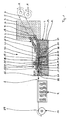
- FIG. 1 1 comprises two unwinding devices A, two feeders 3 and 4 for feeding respectively a plurality of monofilaments of two different types, not illustrated individually, but illustrated only by lines 5 and 6, a cleaning device R, as an essential component Coating device 7, a compacting device 8, a drying device 9 shown only schematically and finally a winding device 10 for winding the monofilament thread 2 on.
- the unwinding devices allow a twist-free unwinding of the bundles of single filaments, so that in particular an over-head unwinding is eliminated.
- the two feeders 3 and 4 are slightly curved tube bodies 11 and 12, through which the individual filaments, which are monofilaments, are guided in isolated form.
- the individual filaments are unrolled by another, not shown, but known from the prior art winding device without rotation.
- both bundles of monofilaments are passed through a bath or curtain of a cleaning liquid (primer) of a cleaning device R before being subsequently pretreated to the coating device.
- the coating device 7 is formed by a container 13, in which a bath of a flowable resin 14 is located, through which pass the respective plurality of individual filaments of the two types. Thus, a dip coating of all individual filaments takes place. Via a connection, not shown, a mirror 15 of the resin bath is kept constant, in particular the continuous consumption of the resin in the thread coating compensated.
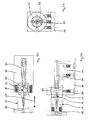
- the compacting device 8 which in the FIGS. 2a to 2c is shown separately in three views, consists of an inner nozzle 16 and a coaxially arranged outer nozzle 17. Both nozzles 16 and 17 are in the Figures 3a, 3b and 4a, 4b again shown in detail in different perspective views.
- the inner nozzle has a frustoconical outer surface 18 and a - having a smaller cone angle - inner lateral surface 19.
- the inner circumferential surface 19 defines an inner space 20 of the inner nozzle 16, wherein in the inner space 20 up to an opening cross section 22 arranged at a tip 21 of the inner nozzle 16, the compaction, i. radial compression, the majority of those individual filaments takes place, which later produce an inner zone of the thread 2.
- the outer nozzle 17 has a stepped cylindrical outer surface 23 and a frusto-conical inner surface whose cone angle is in turn greater than that Cone angle of the outer frusto-conical lateral surface 18 of the inner nozzle 16.
- an outlet cross-section 28 of the outer nozzle 17 is at the end of the compaction process before a monofilament thread 2, which has a relatively dense arrangement of the individual filaments in its cross section, wherein the spaces between the individual filaments are completely filled with resin 14 and have no gas inclusions.
- the outer single filaments wrap around the outer circumferential surface 18 of the inner nozzle 16.
- the outer single filaments form a closed ring which, viewed in cross-section, completely surrounds the individual filaments approximately circular in cross-section which exit from the inner nozzle 16 and form the later inner zone of the filament 2 ,
- the outer cone angle of the inner nozzle 16 is about 1.5 ° to 2.5 °, preferably 2.0 ° and the inner cone angle of the inner nozzle 16 about 10 ° to 15 °, preferably about 12 °.
- the inner cone angle of the outer nozzle is about 15 ° to 20 °, preferably about 18 °.
- the monofilament yarn 2 formed as described above is dried using microwave radiation and / or hot air convection or the like, i. the solvent of the resin 14 formed by water in the present case is removed from the latter, so that the viscosity increases, the adhesive property and thus the cohesion of the individual filaments is improved.
- it only takes place drying in the physical sense and no chemical crosslinking of the monomers of the resin 14th
- the thread 2 After leaving the drying device 9, the thread 2 is stabilized so far and so far has no "sticky" properties more that he on the winding device 10 on corresponding coils 29 can be wound.
- the individual filaments - in the present case both types - are not twisted together at any point of the manufacturing process. Throughout the manufacturing process, the parallel, ie unidirectional, alignment of all single filaments is maintained, as is the case for the finished filament 2 wound on the spool 29.
- FIGS. 1 and FIGS. 2 a to 2 c show that the inner nozzle 16 is fastened to a first nozzle carrier 30.
- the outer nozzle 17 is attached to a second nozzle carrier 31 and screwed with an externally threaded portion 32 in a cooperating internally threaded portion 33 of the nozzle carrier 31.
- a horizontal displacement of the outer nozzle 17 along the double arrow 35 can be achieved.
- both nozzle carriers 30, 31 are screwed to a base plate 36, wherein the base plate 36 is arranged on a bottom surface 37 of the container 13.
- the nozzles 16, 17, the nozzle carrier 30, 31 and the base plate 36 as well as the screws used for connection consist of stainless steel. The same applies to the container 13 and the tubular body 11 and 12 of the feeders 3 and 4.
- the inner nozzle 16 has, following its frustoconical front part, a tubular rear part which adjoins the front part at a step 38. With the rear part, which has an opening cross-section 39, the inner nozzle 16 can be used a correspondingly adapted extended bore portion 40 of a tubular nozzle holder 41, which in turn is connected to the nozzle carrier 30.
- a thread 2 whose inner zone, which is circular in cross-section, consists of approximately 100 to 2000 individual filaments of carbon (carbon).
- An outer zone which is annular in cross-section and arranged around the inner zone, in turn has approximately 100 to 2000 individual filaments.
- These can for example consist of glass or ceramic.
- the diameters of both filament types can be between about 5 ⁇ m and 25 ⁇ m, preferably between about 8 ⁇ m and 20 ⁇ m.
- the individual filaments of one type all have the same diameter, and all filament types may have the same diameter.
- the resin 14 in the present case consists of a silicone resin mixture.
- Particularly suitable is the silicone resin of the company. Wacker Chemie AG, Kunststoff, Germany, which is sold under the name "WS 40".
- the crosslinking of the silicone resin takes place at a later time, when the finished thread 2 is unwound from the bobbin 29 again and processed into a semifinished product or end product (textile fabric or three-dimensional structure) and thus the final shape of the part is fixed.
- the crosslinking temperature is above 140 ° C, preferably a pressure of about up to 500 N / mm 2 is applied.
- the further processing of the uncrosslinked thread 2 is not the subject of the present application.
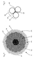
- the alternative thread 2 ' has a three-zone structure with respect to the yarn 2 produced with the device 1.
- An inner zone 42 is surrounded by a first outer zone 43 which is annular in cross-section and which is enclosed in turn radially outwards by a second outer zone 44 of annular cross-section.
- the individual filaments 45 of the inner zone are formed by carbon fibers, the individual filaments 46 of the first outer zone 43 made of basalt and the individual filaments 47 of the second outer zone 44 made of silicone. It should be noted that the representation of the individual filaments 45 to 47 is not to scale with respect to the number present in each zone.
- the thread 2 as a product of the device 1, preferably at least about 100 individual filaments are present in the inner zone 42.
- the two outer zones 43, 44 there are typically correspondingly more, ie between approximately 500 and 1500, depending on the selected layer thicknesses.
- the thread 2 ' like all threads produced by the method according to the invention, is characterized by a very high packing density of the individual filaments 45 to 47 in all three zones.
- Spaces 48 the in FIG. 6 are exemplified by three exemplary selected individual filaments 47, have in cross-section a typical gusset shape (triangle with curved sides).
- contact lines 49 or contact surfaces are thin intermediate layers of resin, whereby the strength of the composite of individual filaments 47 and resin for later crosslinking of the resin is improved.
- resin 14 is also in a limited by the dashed line 50 area around the individual filaments 47 around and also in the formed between adjacent individual filaments 47 gussets 51. Overall, the resin consumption at the inventive method or thread 2 and 2 'minimized.
- Aramid in particular para-aramid monofilament, is used in particular because of the high price, if the strength properties or the ratio of strength and mass is important (aerospace, security technology, etc.).
- Glass fiber is a cost effective material with satisfactory properties. If high temperature resistance is required, ceramic or basalt fibers may be used.
- Abrasion-resistant monofilaments are usually used in the outer zone, those with high tensile strength usually in the inner zone.
Description
Die Erfindung betrifft ein Verfahren zur Herstellung eines Fadens, der eine Mehrzahl von Einzelfilamenten besitzt. Darüber hinaus betrifft die Erfindung eine Vorrichtung zur Herstellung eines Fadens, der eine Mehrzahl von Einzelfilamenten besitzt.The invention relates to a method for producing a thread which has a plurality of individual filaments. Moreover, the invention relates to a device for producing a thread which has a plurality of individual filaments.
Verfahren und Vorrichtungen zur Herstellung von aus einer Mehrzahl von Einzelfilamenten bestehenden Fäden (Garnen) sowie derartige Fäden sind in großer Vielzahl allgemein bekannt. Um die Festigkeit und den Zusammenhalt der Einzelfilamente, unter denen im Sinne der vorliegenden Anmeldung Monofilamente zu verstehen sind, im fertigen Faden zu verbessern, insbesondere wenn es sich bei den Einzelfilamenten um Stapelfasern, d.h. Filamente mit relativ kleiner Länge, handelt, werden die Einzelfilamente im Wege eines Spinnverfahrens miteinander verdreht. Alternativ zur Drehung können Einzelfilamente auch unter Verwendung von aushärtenden oder aushärtbaren Harzen quasi miteinander verklebt werden, um einen Verbund mit hinreichendem Zusammenhalt zu erzielen. Es handelt sich bei derartigen Fäden mit Harzanteil um einen Faserverbund-Werkstoff.Methods and apparatus for making yarns consisting of a plurality of single filaments and such yarns are well known in wide variety. In order to improve the strength and cohesion of the individual filaments, which are to be understood in the context of the present application monofilaments, in the finished yarn, in particular when it comes to the individual filaments staple fibers, i. Filaments are relatively small in length, the individual filaments are twisted together by a spinning process. As an alternative to rotation, single filaments can also be glued together, as it were, using thermosetting or curable resins, in order to achieve a bond with sufficient cohesion. It is in such threads with resin content to a fiber composite material.
Nachteilig bei den bekannten Fäden ist, dass sich daraus im Rahmen einer Weiterverarbeitung hergestellte textile Flächengebilde (Gewebe, Gewirke, Gestricke, Gelege, Vliese, o.ä.) oder wiederum aus diesen textilen Flächengebilden im Zuge weiterer Verarbeitung hergestellte Halbzeuge (Profile, Platten, Leisten, o. ä.) im Hinblick auf ihre statischen und dynamischen Eigenschaften nur sehr schwer berechnen lassen. Insbesondere versagt bei aus Fäden bestehenden Gebilden die Finite-Elemente-Methode (FEM), die in weiten Bereichen der Festkörperstatik mit den großen, heutzutage zur Verfügung stehenden Rechnerkapazitäten eine recht exakte numerische Bestimmung der Belastung in einem Bauteil ermöglicht.A disadvantage of the known threads is the fact that textile fabrics produced therefrom in the course of a further processing (woven, knitted or knitted fabrics, scrims, nonwovens, or the like) or in turn made of these textile fabrics in the course of further processing (profiles, sheets, Bars, etc.) are very difficult to calculate in terms of their static and dynamic properties. In particular, in the case of structures consisting of threads, the finite element method (FEM) fails, which permits a fairly exact numerical determination of the load in a component in many areas of solid state statics with the large computer capacities available today.
Darüber hinaus liegt ein Nachteil bekannter Verbundwerkstoffe aus Fäden und diese zusammen haltenden Harzen darin, dass der Harzanteil sehr hoch ist. Dies reduziert nicht nur die Festigkeit derartiger Verbundwerkstoffe, sondern erhöht auch die Kosten da die Harze vergleichsweise teuer sind. Darüber hinaus ist die Verwendung großer Mengen von Harzen auch unter Umweltgesichtspunkten bzw. dem Aspekt der Ressourcenschonung kritisch zu betrachten, weil die Harze in den meisten Fällen aus Rohölprodukten hergestellt sind.In addition, a disadvantage of known composites of filaments and these resins holding together is that the resin content is very high. This not only reduces the strength of such composites, but also increases the cost of the resins are relatively expensive. In addition, the use of large quantities of resins is also critical from an environmental point of view or resource conservation, because in most cases the resins are made from crude oil products.
In der
Um dieses zu vermeiden wird in der
Der Erfindung liegt die Aufgabe zugrunde, ein Verfahren und eine Vorrichtung zur Herstellung eines Fadens vorzuschlagen, mit dem bzw. der sich Fäden (Garne) herstellen lassen, die zur Weiterverarbeitung zu textilen Flächengebilden oder unter deren Verwendung hergestellter Halbfabrikate geeignet sind, die sich wiederum durch eine hohe Festigkeit, eine einfache numerische Berechenbarkeit der mechanischen Belastungszustände und durch einen geringen Harzverbrauch auszeichnen.The invention has for its object to provide a method and an apparatus for producing a thread with which or can produce threads (yarns), which are suitable for further processing into textile fabrics or semi-finished products using their manufacture, which in turn a high strength, a simple numerical predictability of the mechanical load conditions and characterized by a low resin consumption.
In verfahrenstechnischer Hinsicht wird die vorgenannte Aufgabe ausgehend von einem Verfahren der eingangs genannten Art dadurch gelöst, dass die Einzelfilamente vorzugsweise jeweils voneinander beabstandet endlos geführt und mit einem fließfähigen, ein Lösungsmittel enthaltenden und durch Einwirkung mindestens einer physikalischen Größe und/oder eines chemischen Stoffs vernetzbaren Harz beschichtet werden, wobei die beschichteten Einzelfilamente anschließend kompaktiert werden, so dass ein aus den Einzelfilamenten und dem diese zusammenhängend umgebenden Harz bestehender und von Gaseinschlüssen freier Verbund gebildet wird, aus dem im folgenden während eines Trocknungsvorgangs das in dem Harz enthaltene Lösungsmittel ausgetrieben wird, wobei der dann als monofiler Faden vorliegende Verbund in einem unvernetzten Zustand des Harzes aufgewickelt wird, wobei alle Einzelfilamente während sämtlicher vorstehender Verfahrensschritte in paralleler (d.h. unidirektionaler) Ausrichtung gehalten werden und ferner die Einzelfilamente vor der Beschichtung mit dem Harz auf eine Temperatur zwischen 50° C bis 80° C aufgewärmt werden.In procedural terms, the above object is achieved by a method of the type mentioned in that the individual filaments preferably each spaced from each other endlessly and with a flowable, solvent-containing and crosslinkable by the action of at least one physical size and / or a chemical substance resin are coated, wherein the coated individual filaments are then compacted, so that one of the Single filaments and this coherent surrounding resin existing and gas-entail free composite is formed, from which is expelled in the following during a drying process, the solvent contained in the resin, wherein the then present as a monofilament yarn composite is wound in an uncrosslinked state of the resin, wherein all individual filaments are held in parallel (ie, unidirectional) orientation during all of the above process steps, and further, the individual filaments are heated to a temperature between 50 ° C to 80 ° C prior to coating with the resin.
Die Erfindung geht zunächst von der Erkenntnis aus, dass das Verdrehen der Einzelfilamente eines Fadens, wie es im Stand der Technik standardmäßig und selbstverständlich angewendet wird, dann sehr von Nachteil ist, wenn aus dem gedrehten Faden in weiteren Verarbeitungsschritten ein textiles Flächengebilde (als Bestandteil eines späteren, Harz enthaltenden Verbundwerkstoffs) und daraus eventuell weitere Halbfabrikate unter Zusatz von Harz hergestellt werden sollen. Die Verdrehung der Einzelfilamente ist nämlich bei einem späteren Verbinden einer Mehrzahl von Fäden unter Verwendung eines fließfähigen Harzes zu einem Faserverbundwerkstoff sehr von Nachteil, weil ein Eindringen des Harzes in die zentralen Bereiche um die Längsachse des Fadens herum nahezu ausgeschlossen ist, da die verdrehten Einzelfilamente den inneren Bereich quasi dicht verschließen und vor einem Eindringen des Harzes abschirmen. Hieraus ergibt sich ein Festigkeitsverlust für den Faden, weil dieser in seinem Inneren aufgrund des fehlenden Harzes keinen genügenden Zusammenhalt besitzt.The invention is based first of the recognition that the twisting of the individual filaments of a thread, as it is standard and of course used in the prior art, then very disadvantageous if from the twisted thread in further processing steps, a textile fabric (as part of a later, resin-containing composite material) and from this possibly further semifinished products with the addition of resin to be produced. The twisting of the individual filaments is in fact at a later joining of a plurality of threads using a flowable resin to a fiber composite very disadvantageous because penetration of the resin in the central regions around the longitudinal axis of the thread is almost impossible because the twisted single filaments the Close the inner area almost tightly and shield it against penetration of the resin. This results in a loss of strength for the thread, because this does not have sufficient cohesion in its interior due to the lack of resin.
Dieses Problem wird mit dem erfindungsgemäßen Verfahren durch die Beschichtung bereits der Einzelfilamente und anschließende Kompaktierung gelöst, wodurch ein Verbund erzeugt wird, der über seinen gesamten Querschnitt ausschließlich aus den Einzelfilamenten und dem diese umgebenden Harz besteht. Durch ein geeignetes Kompaktierungsverfahren sind Gaseinschlüsse in dem Querschnitt des Verbunds ausgeschlossen. Bei Fäden, die nach dem erfindungsgemäßen Verfahren hergestellt sind, ist damit - nach einem Vernetzen des Harzes - auch im Inneren des Fadens ein hervorragender Zusammenhalt gegeben, da auch dort die Klebewirkung des Harzes in vollem Umfang eintritt. Die Festigkeit wird somit deutlich gesteigert und die Möglichkeiten, die Belastung numerisch zu bestimmen, verbessert.This problem is solved with the inventive method by the coating already the individual filaments and subsequent compaction, whereby a composite is produced, which consists over its entire cross section exclusively of the individual filaments and the surrounding resin. By a suitable compaction process gas inclusions are excluded in the cross section of the composite. In the case of threads which are produced by the process according to the invention, an excellent cohesion is thus also present in the interior of the thread after cross-linking of the resin, since the adhesive effect of the resin also fully occurs there. The strength is thus significantly increased and the possibilities to numerically determine the load improves.
Die Erfindung beruht jedoch noch auf der zusätzlichen Erkenntnis, dass bei der Weiterverarbeitung von Fäden zu textilen Flächengebilden oder daraus unter Harzzugabe im Weiteren hergestellten Halbfabrikaten eine Verwendung von Fäden mit ausgehärtetem Harz (ebenso wie die Verwendung gedrehter, aber kein Harz enthaltender Fäden) nicht zielführend ist, sondern eine hervorragende Verbindung der Einzelfilamente in dem textilen Flächengebilde oder den daraus hergestellten Halbfabrikaten dann erzielt wird, wenn die Vernetzung des Harzes erst dann vorgenommen wird, wenn die Fäden in die Form gebracht worden sind, die sie im endgültigen Produkt besitzen sollen. Da die Fäden im unvernetzten Harzzustand erfindungsgemäß noch relativ zueinander bewegliche und parallel zueinander verlaufende Einzelfilamente besitzen, ergibt sich zwischen benachbarten Fäden einer daraus herzustellenden größeren Struktur ein sehr guter Kontakt mit größtmöglichen Kontaktflächen. So ist unter Druck eine sehr weitreichende Abflachung oder Abplattung der Fäden zu erzielen (in Richtung auf einen Rechteckquerschnitt), woraus sich quasiflächige Kontaktflächen zwischen sich z.B. kreuzenden Fäden ergeben. Dies führt wiederum zu einer besonderen Festigkeit des hergestellten Produkts nach Vernetzung des Harzes und senkt aufgrund des hohen Anteils der Einzelfilamente am fertigen Produkt den Verbrauch des Harzes enorm, da die nicht von den Einzelfilamenten ausgefüllten Freiräume drastisch reduziert werden.However, the invention is still based on the additional finding that in the further processing of threads into textile fabrics or semifinished products made therefrom with resin addition, use of threads with hardened resin (as well as the use of twisted threads but not containing resin) is not expedient but excellent bonding of the single filaments in the fabric or semi-finished products made therefrom is achieved when the cross-linking of the resin is not made until the filaments have been formed into the shape they are to have in the final product. According to the invention, since the threads in the uncrosslinked resin state still have relatively movable individual filaments running parallel to one another, a very good contact with the largest possible contact surfaces results between adjacent threads of a larger structure to be produced therefrom. Thus, a very far-reaching flattening or flattening of the threads can be achieved under pressure (in the direction of a rectangular cross-section), resulting in quasi-surface contact surfaces between, for example, crossing threads. This in turn leads to a special strength of the product produced after crosslinking of the resin and lowers the consumption of the resin enormously due to the high proportion of individual filaments on the finished product, since the spaces not filled by the individual filaments are drastically reduced.
Die Erfindung lehrt somit, die Vernetzung des Harzes solange zurückzustellen, bis nach einem oder mehreren weiteren Verfahrensschritten, die sämtlich nach Abschluss der Fadenherstellung erfolgen, die gewünschte Endform der herzustellenden Struktur erreicht um das Bindungspotenzial des Harzes erst dann einzusetzen, wenn damit im fertigen Produkt ein Verbund zwischen einer Mehrzahl von Fäden bzw. der darin enthaltenen Einzelfilamente erzielt werden kann. Mit der Erfindung wird also ein neues Halbfabrikat "Multifilamentfaden mit unvernetztem Harz" (mit unidirektionaler Ausrichtung der Einzelfilamente) geschaffen, bei dem das Harz nach seiner Trocknung die wesentliche Zwischenaufgabe erfüllt, den Einzelfilament-Verbund zu einem handhabbaren Monofilament-Faden zusammenzufügen und während der später folgenden Verarbeitungsschritte in dieser Form zu erhalten. Dies gilt z.B. für das spätere Transportieren, Abwickeln, Verweben, Verstricken, Verwirken oder bei der Vliesherstellung usw. Fäden zu Fertigprodukten oder Halbfabrikaten auf dem Weg zu weiteren Fertigprodukten. Man erhält folglich unter dem Aspekt der Handhabung einen monofilen Faden, der jedoch aufgrund des unvernetzten Harzes vor dem späteren Vernetzungsvorganginsbesondere unter Druckbelastung - unter Verschiebung der Einzelfilamente relativ zueinander verfasst werden kann, wobei die kompaktierte Form nach der Vernetzung als endgültige Form des Fertigprodukts oder des Halbfabrikats erhalten bleibt. Die Trocknung des Harzes (d.h. die Lösungsmittel-Entfernung) muss wenigstens soweit erfolgen, dass die Viskosität des Harzes zum einen den Zusammenhalt der Einzelfilamente sicherstellt, und zum anderen verhindert, dass der aufgewickelte Faden zwischen benachbarten Windungen oder Fäden auf einer Spule verklebt und dann nicht mehr ordnungsgemäß für die weitere Verwendung abspulbar ist. Um das Anhaften des Harzes an den Einzelfilamenten zu verbessern und das Einschleppen von Luft in das Harzbad zu reduzieren, werden die Einzelfilamente vor der Beschichtung mit dem Harz auf eine Temperatur zwischen 50° C bis 80° C aufgewärmt.The invention thus teaches to postpone the crosslinking of the resin until, after one or more further process steps, all of which take place after the yarn preparation has been completed, the desired final shape of the structure to be produced is achieved in order to use the binding potential of the resin only when it is present in the finished product Composite between a plurality of threads or the individual filaments contained therein can be achieved. The invention thus provides a new semi-finished product "multifilament yarn with uncrosslinked resin" (with unidirectional alignment of the individual filaments), in which the resin, after drying, performs the essential intermediate task of joining the single filament composite into a manageable monofilament thread and during the later to receive the following processing steps in this form. This applies, for example, for later transporting, unwinding, weaving, knitting, forking or fleece production, etc. threads to finished products or semi-finished products on the way to other finished products. Thus, from the aspect of handling, a monofilament thread is obtained, but owing to the uncrosslinked resin, can be written relative to one another prior to the later cross-linking operation, particularly under compressive loading, shifting the single filaments, with the compacted form after cross-linking as the final shape of the finished product or semifinished product preserved. The drying of the resin (ie, the solvent removal) must at least be done so far that the viscosity of the resin on the one hand ensures the cohesion of individual filaments, and on the other hand prevents the coiled thread between adjacent turns or threads on a spool glued and then not is properly reusable for further use. In order to improve the adhesion of the resin to the individual filaments and to reduce the entrainment of air in the resin bath, The individual filaments are heated to a temperature between 50 ° C to 80 ° C before coating with the resin.
Eine besonders einfache Art und Weise der Harzbeschichtung besteht darin, die Einzelfilamente durch Tauchen in einem Bad des Harzes zu beschichten, wobei die Einzelfilamente vorzugsweise kontinuierlich durch das Bad gezogen werden. Hierdurch lässt sich ein sehr gleichmäßiger Harzauftrag erzielen und es entstehen nahezu keine Harzverluste durch Material, das bei alternativen Beschichtungsmethoden die Filamente eventuell nicht erreicht. Auch können die Volumina derartiger Bäder sehr klein gehalten werden, was bei einem Wechsel des Harzmaterials oder bei Stillstand von Vorteil ist.A particularly simple manner of resin coating is to coat the individual filaments by immersion in a bath of the resin, wherein the individual filaments are preferably drawn continuously through the bath. As a result, a very uniform resin application can be achieved and there are almost no resin losses due to material that may not reach the filaments in alternative coating methods. Also, the volumes of such baths can be kept very small, which is advantageous in a change of the resin material or at standstill.
Die Erfindung weiter ausgestaltend wird vorgeschlagen, für die Kompaktierung der Einzelfilamente mindestens eine Düse zu verwenden, durch die die Mehrzahl der beschichteten Einzelfilamente gezogen wird. Dabei sollte ein Innenraum der Düse kegelstumpfförmig sein, so dass beim Austritt der kompaktierten Einzelfilamente aus einem Öffnungsquerschnitt der Düse überschüssiges Harz im Innenraum der Düse zurückgehalten wird. Durch den sich auf die Austrittsöffnung verengenden Düsenquerschnitt wird im Zuge der Bewegung der Einzelfilamente ein Staudruck erzeugt, der zum einen ein gutes Ausfüllen des gesamten späteren Fadenquerschnitts mit Harz, insbesondere auch des Zentralbereichs ermöglicht und somit mögliche Gasbestandteile in dem späteren Fadenquerschnitt quasi vollständig entfernt. Vorzugsweise befinden sich die Düsen in einem Bad des Harzes.The invention further ausgestaltend it is proposed to use for the compaction of the individual filaments at least one nozzle through which the majority of the coated individual filaments is pulled. In this case, an interior of the nozzle should be frustoconical, so that excess resin is retained in the interior of the nozzle at the outlet of the compacted individual filaments from an opening cross-section of the nozzle. As a result of the nozzle cross-section narrowing on the outlet opening, a dynamic pressure is generated in the course of the movement of the individual filaments which, on the one hand, permits a good filling of the entire later thread cross-section with resin, in particular also of the central region, thus virtually completely eliminating possible gas components in the later thread cross-section. Preferably, the nozzles are in a bath of the resin.
In besonders vorteilhafter Weise lässt sich das anmeldungsgemäße Verfahren mit den nachfolgenden Filamenttypen durchführen:
- a. Filamente aus synthetischen Polymeren, insbesondere aus Aramid, vorzugsweise aus Para-Aramid,
- b. Filamente aus Kohlenstoff (Carbon),
- c. Filamente aus Glas,
- d. Filamente aus Mineralien, insbesondere aus Basalt
- e. Filamente aus Metall (Draht), insbesondere aus Stahl.
- a. Filaments of synthetic polymers, in particular of aramid, preferably of para-aramid,
- b. Filaments of carbon,
- c. Filaments of glass,
- d. Filaments of minerals, in particular of basalt
- e. Filaments of metal (wire), in particular of steel.
Vorzugsweise sollten die Einzelfilamente einen Durchmesser im Bereich zwischen 3 µm und 30 µm, vorzugsweise zwischen 4 µm und 20 µm, weiter vorzugsweise zwischen 6 µm und 10 µm, besitzen und/oder der kompaktierte Verbund einen Durchmesser im Bereich zwischen 3 µm und 30 µm, vorzugsweise zwischen 4 µm und 20 µm, weiter vorzugsweise zwischen 6 µm und 10 µm besitzen und/oder der kompaktierte Verbund einen Durchmesser im Bereich zwischen 150 µm und 10 mm, vorzugsweise zwischen 200 µm und 2 mm, weiter vorzugsweise zwischen 250 µm und 1,0 mm besitzt und/oder der getrocknete monofile Faden eine Durchmesser im Bereich zwischen 120 µm und 10 mm, vorzugsweise zwischen 160 µm und 1,6 mm, weiter vorzugsweise zwischen 220 µm und 0,9 mm besitzen.Preferably, the individual filaments should have a diameter in the range between 3 μm and 30 μm, preferably between 4 μm and 20 μm, more preferably between 6 μm and 10 μm, and / or the compacted composite should have a diameter in the range between 3 μm and 30 μm. preferably between 4 μm and 20 μm, more preferably between 6 μm and 10 μm, and / or the compacted composite has a diameter in the range between 150 μm and 10 mm, preferably between 200 μm and 2 mm, more preferably between 250 μm and 1.0 mm, and / or the dried monofilament thread has a diameter in the range between 120 μm and 10 mm, preferably between 160 μm and 1 , 6 mm, more preferably between 220 .mu.m and 0.9 mm.
Ferner sollte der monofile Faden aus einer Anzahl von Einzelfilamenten aus den folgenden Intervallen zusammengesetzt ist: 100 bis 3000, vorzugsweise 150 bis 2000, weiter vorzugsweise 200 bis 1000.Further, the monofilament yarn should be composed of a number of single filaments from the following intervals: 100 to 3,000, preferably 150 to 2,000, more preferably 200 to 1,000.
Das verwendete Harz kann aus der Gruppe der folgenden Harztypen ausgewählt werden:
- a) Phenol-Formaldehydharz,
- b) Aminoplasthart,
- c) Epoxydharz,
- d) Polyesterharz,
- e) ABS-Harz,
- f) Silikonharz,
- a) phenol-formaldehyde resin,
- b) aminoplastics,
- c) epoxy resin,
- d) polyester resin,
- e) ABS resin,
- f) silicone resin,
Gemäß einer Weiterbildung der Erfindung wird vorgeschlagen, dass das Harz einen Lösungsmittelanteil, vorzugsweise einen Wasseranteil, zwischen 10 % und 70 %, vorzugsweise zwischen 20 % und 50 %, weiter vorzugsweise zwischen 30 % und 40 % besitzt.According to one embodiment of the invention it is proposed that the resin has a solvent content, preferably a water content, between 10% and 70%, preferably between 20% and 50%, more preferably between 30% and 40%.
Gemäß einer besonders bevorzugten Ausgestaltung des erfindungsgemäßen Verfahrens kann das Lösungsmittel aus dem beschichteten und kompaktierten Verbund mittels Konvektion mit zwangsgeförderter Luft und/oder mittels elektromagnetischer Strahlung, insbesondere Infrarotstrahlung oder Mikrowellenstrahlung, ausgetrieben werden. Dabei sollte die Temperatur bei dem Trocknungsvorgang vorzugsweise im Bereich zwischen 70° C und 110° C, vorzugsweise zwischen 80° C und 100° C, gehalten werden, um eine ungewollte Vernetzung sicher auszuschließen.According to a particularly preferred embodiment of the method according to the invention, the solvent can be expelled from the coated and compacted composite by means of convection with positively conveyed air and / or by means of electromagnetic radiation, in particular infrared radiation or microwave radiation. The temperature during the drying process should preferably be kept in the range between 70 ° C and 110 ° C, preferably between 80 ° C and 100 ° C, to safely exclude unwanted crosslinking.
Vorzugsweise werden die Einzelfilamente vor der Beschichtung auf eine Temperaturniveau zwischen 60°C und 70°C aufgewämt, um das Anhaften des Harzes an den Einzelfilamenten zu verbessern und das Einschleppen von Luft in das Harzbad zu reduzieren.Preferably, the single filaments are coated to a temperature level between 60 ° C and 70 ° C prior to coating to improve the adhesion of the resin to the single filaments and to reduce the entrainment of air into the resin bath.
Um Fäden mit besonderen Eigenschaften zu erzielen und diese hinsichtlich mehrere Anforderungen zu optimieren, kann sich in einer Innenzone des kompaktierten Verbundes der Einzelfilamente ein erster Typ von Einzelfilamenten befinden, während sich in mindestens einer sich radial nach außen an die Innenzone anschließenden Außenzone ein anderer Typ von Einzelfilamenten befindet. Optional kann sich an einen solchen Fadentyp, der aus einer "Seele" und einem (ersten) "Mantel" besteht, weiter radial nach außen ein weiterer "Mantel" in Form einer zweiten Außenzone anschließen, in der ein anderer Typ von Einzelfilamenten als in der ersten Außenzone angeordnet ist. Auf diese Weise lassen sich Fäden mit optimalen Eigenschaften für unterschiedliche Anwendungen erzielen, z.B. für eine reine Festigkeitsoptimierung, eine Verschleißoptimierung, den Brandschutz, die Wärmeisolierung, die Schalldämmung o. ä.. Bei derartigen Fäden mit voneinander abgegrenzten Bereichen verschiedener Typen von Einzelfilamenten sollten die Grenzen zwischen den jeweiligen Zonen von Zylinderflächen gebildet werden, die koaxial zu einer Fadenlängsachse ausgerichtet sind.In order to achieve threads with special properties and to optimize these with respect to several requirements, a first type of single filaments may be located in an inner zone of the compacted composite of the individual filaments, while in another outer zone adjoining the inner zone radially outwards another type of single filaments may be present Single filaments is located. Optionally, to such a thread type, which consists of a "soul" and a (first) "coat", further radially outward another "coat" in the form of a second outer zone join, in which a different type of single filaments than in the first outer zone is arranged. In this way, threads with optimum properties for different applications can be achieved, e.g. For pure strength optimization, wear optimization, fire protection, thermal insulation, sound insulation o. Ä .. In such threads with delimited areas of different types of single filaments, the boundaries between the respective zones of cylindrical surfaces should be formed coaxially aligned with a thread longitudinal axis are.
Der Harzfluss während des Beschichtungsvorgangs wird verbessert und damit der Verbleib von Lufteinschlüssen in dem Harz-Einzelfilament-Verbund vermieden, wenn die Einzelfilamente vor der Beschichtung gereinigt, insbesondere in einem Bad einer Reinigungsflüssigkeit gewaschen und/oder mit einer dem Harzfluss fördernden Vorbeschichtung versehen werden, wobei die Einzelfilamente (45, 46, 47) während der Reinigung vorzugsweise vereinzelt geführt werden.The flow of resin during the coating process is improved, thereby avoiding air entrainment in the resin monofilament composite, when the monofilaments are cleaned prior to coating, especially washed in a bath of cleaning fluid, and / or provided with a resin flow promoting precoat the individual filaments (45, 46, 47) are preferably separated during cleaning.
In vorrichtungstechnischer Hinsicht wird die zugrunde liegende Aufgabe durch eine Vorrichtung zur Herstellung eines Fadens, der eine Mehrzahl von Einzelfilamenten besitzt, gelöst, wobei die Vorrichtung die folgenden Merkmale aufweist:
- mindestens eine Zuführeinrichtung für die Mehrzahl der parallel zueinander ausgerichteten Einzelfilamente,
- eine Beschichtungseinrichtung, mit der die jeweils vorzugsweise in einem Abstand zueinander geführten Einzelfilamente an ihren Mantelflächen mit einem fließfähigen, ein Lösungsmittel enthaltenen und durch Einwirkung mindestens einer physikalischen Größe und/oder eines chemischen Stoffs vernetzbaren Harz beschichtbar sind,
- eine Kompaktierungseinrichtung, mit dem der von der Mehrzahl der Einzelfilamente und dem anhängenden Harz eingenommene Querschnitt so verkleinerbar ist, dass ein aus den Einzelfilamenten und dem diese zusammenhängend umgebenden Harz bestehender und von Gaseinschlüssen freier Verbund erzeugbar ist,
- eine Trocknungseinrichtung, mit der das in dem Harz enthaltene Lösungsmittel aus dem kompaktierten Verbund austreibbar ist und
- einer Wickeleinrichtung, mit der der getrocknete Verbund zugspannungsminimiert so aufwickelbar ist, dass die Einzelfilamente verdrehungsfrei angeordnet sind.
- at least one feed device for the plurality of individual filaments oriented parallel to one another,
- a coating device with which the individual filaments, which are preferably each guided at a distance from one another, can be coated on their lateral surfaces with a flowable resin containing a solvent and crosslinkable by the action of at least one physical variable and / or chemical substance,
- a compacting device, with which the cross-section occupied by the plurality of individual filaments and the adhering resin can be made smaller such that a composite consisting of the individual filaments and the resin surrounding them and of gas inclusions can be produced,
- a drying device, with which the solvent contained in the resin is expelled from the compacted composite, and
- a winding device with which the dried composite is minimized zugspannungsminimiert so that the individual filaments are arranged torsion-free.
Mit einer derartigen Vorrichtung lässt sich das erfindungsgemäße Verfahren auf besonders einfache Weise durchführen.With such a device, the inventive method can be carried out in a particularly simple manner.
Vorzugsweise umfasst die Beschichtungseinrichtung ein Behältnis mit einem Bad des Harzes, durch dass die Mehrzahl der Einzelfilamente vereinzelt führbar ist.The coating device preferably comprises a container with a bath of the resin, by means of which the majority of the individual filaments can be guided individually.
Um auf einfache Weise gute Kompaktierungsergebnisse zu erzielen, sollte die Kompaktierungseinrichtung mindestens eine Düse umfassen, deren Innenraum eine Kegelstumpfform besitzt. Vorzugsweise ist mindestens die Düse in dem Harzbad angeordnet.In order to achieve good compacting results in a simple manner, the compacting device should comprise at least one nozzle whose interior has a truncated cone shape. Preferably, at least the nozzle is disposed in the resin bath.
Um Fäden mit mindestens zwei Zonen mit unterschiedlichen Typen von Einzelfilamenten herstellen zu können und somit Fäden mit kombinierten Eigenschaften zu erzeugen, wird vorgeschlagen, dass die Kompaktierungseinrichtung eine Innendüse und eine koaxial zu dieser angeordnete Außendüse aufweist. Zwischen einer Spitze der Innendüse und einer inneren Mantelfläche der einen kegelsturnpfförmigen Innenraum aufweisenden Außendüse befindet sich vorzugsweise ein Ringspalt. In diesem Fall ist somit durch einen Öffnungsquerschnitt der Innendüse eine Mehrzahl von Einzelfilamenten eines ersten Typs und durch den Ringspalt zwischen den Düsen eine Mehrzahl von Einzelfilamenten eines zweiten Typs führbar. Auf diese Weise kann an einem Austrittsquerschnitt der Außendüse ein kompaktierter Verbund erzeugt werden (Kombinationsverbund), der eine Innenzone aus Einzelfilamenten des ersten Typs und eine Außenzone aus Einzelfilamenten des zweiten Typs besitzt. Um einen guten Zusammenhalt der Einzelfilamente und später eine hohe Festigkeit des erzeugten Endprodukts zu gewährleisten, sind die Zwischenräume zwischen sämtlichen Einzelfilamenten beider Typen vollständig mit Harz ausgefüllt und sämtliche Einzelfilamente beider Typen verlaufen in dem Kombinationsverbund parallel zueinander.In order to be able to produce threads with at least two zones with different types of single filaments and thus produce threads with combined properties, it is proposed that the compacting device has an inner nozzle and an outer nozzle arranged coaxially therewith. An annular gap is preferably located between a tip of the inner nozzle and an inner circumferential surface of the external nozzle having a cone-shaped interior. In this case, therefore, a plurality of individual filaments of a first type can be guided through an opening cross-section of the inner nozzle, and a plurality of individual filaments of a second type can be guided through the annular gap between the nozzles. In this way, at an outlet cross-section of the outer nozzle, a compact composite can be produced (composite composite) having an inner zone of single filaments of the first type and an outer zone of single filaments of the second type. In order to ensure a good cohesion of the individual filaments and later a high strength of the final product produced, the spaces between all single filaments of both types are completely filled with resin and all individual filaments of both types are parallel in the combination compound.
Eine Feinabstimmung der Vorrichtung während des Kompaktierungsvorgangs kann die Außendüse in axiale Richtung zu der Innendüse verschiebbar und in unterschiedlichen Positionen feststellbar sein.Fine tuning of the device during the compaction process, the outer nozzle in the axial direction to the inner nozzle slidably and be determined in different positions.
Erfindungsgemäß beträgt der bevorzugte Anteil des Harzes an dem gesamten Volumen des Faden zwischen 2 % und 15 %, weiter vorzugsweise zwischen 5 % und 12 %.According to the invention, the preferred proportion of the resin in the total volume of the thread is between 2% and 15%, more preferably between 5% and 12%.
Die Erfindung wird nachfolgend anhand eines Ausführungsbeispiels einer Vorrichtung zur Durchführung des Verfahrens sowie eines erfindungsgemäßen Fadens, näher erläutert.The invention will be explained in more detail below with reference to an exemplary embodiment of a device for carrying out the method and a thread according to the invention.
Es zeigt:
- Fig. 1:
- Einen Längsschnitt durch eine Vorrichtung,
- Fig. 2a bis 2c:
- eine Draufsicht, eine Seitenansicht und eine Vorderansicht einer Kompaktierungseinrichtung der Vorrichtung gemäß
Fig. 1 , - Fig. 3a und 3b:
- zwei perspektivische Ansichten einer Außendüse mit eingesetzter Innendüse der Kompaktierungseinrichtung gemäß den
Fig. 2a bis 2c , - Fig. 4a und 4b:
- jeweils eine Ansicht einer Außendüse sowie einer Innendüse der Kompaktierungseinrichtung gemäß den
Fig. 2a bis 2c , - Fig. 5:
- einen Querschnitt durch einen Faden mit einer Innenzone und zwei Außenzonen,
- Fig. 6:
- einen vergrößerten Ausschnitt aus
Fig. 5 mit drei benachbarten Einzelfilamenten.
- Fig. 1:
- A longitudinal section through a device,
- 2a to 2c:
- a plan view, a side view and a front view of a compaction device of the device according to
Fig. 1 . - 3a and 3b:
- two perspective views of an outer nozzle with inserted inner nozzle of the compacting device according to the
Fig. 2a to 2c . - FIGS. 4a and 4b:
- in each case a view of an outer nozzle and an inner nozzle of the compacting device according to the
Fig. 2a to 2c . - Fig. 5:
- a cross section through a thread with an inner zone and two outer zones,
- Fig. 6:
- an enlarged section
Fig. 5 with three adjacent individual filaments.
Eine in
Die Abwickeleinrichtungen ermöglichen ein verdrehungsfreies Abwickeln der Bündel von Einzelfilamenten, so dass insbesondere ein Über-Kopf-Abwickeln ausscheidet.The unwinding devices allow a twist-free unwinding of the bundles of single filaments, so that in particular an over-head unwinding is eliminated.
Bei den beiden Zuführeinrichtungen 3 und 4 handelt es sich um leicht gekrümmte Rohrkörper 11 und 12, durch die hindurch die Einzelfilamente, bei denen es sich um Monofilamente handelt, in vereinzelter Form hindurch geführt werden. Die Einzelfilamente werden von einer weiteren nicht dargestellten aber aus dem Stand der Technik bekannten Wickeleinrichtung jeweils verdrehungsfrei abgewickelt.The two
Zunächst werden beide Bündel von Monofilamenten durch ein Bad oder einen Vorhang einer Reinigungsflüssigkeit (Primer) einer Reinigungseinrichtung R geführt, bevor sie anschließend solchermaßen vorbehandelt zu der Beschichtungseinrichtung geleitet werden.First, both bundles of monofilaments are passed through a bath or curtain of a cleaning liquid (primer) of a cleaning device R before being subsequently pretreated to the coating device.
Die Beschichtungseinrichtung 7 wird gebildet von einem Behältnis 13, in dem sich ein Bad eines fließfähigen Harzes 14 befindet, durch das die jeweilige Mehrzahl der Einzelfilamente der beiden Typen hindurch laufen. Es findet somit eine Tauchbeschichtung sämtlicher Einzelfilamente statt. Über einen nicht dargestellten Anschluss wird ein Spiegel 15 des Harzbades konstant gehalten, insbesondere der fortlaufende Verbrauch des Harzes bei der Fadenbeschichtung ausgeglichen.The coating device 7 is formed by a
Die Kompaktierungseinrichtung 8, die in den
Die innere Düse weist eine kegelstumpfförmige äußere Mantelfläche 18 und eine - einen kleineren Kegelwinkel aufweisende - innere Mantelfläche 19 auf. Die innere Mantelfläche 19 begrenzt einen Innenraum 20 der inneren Düse 16, wobei in dem Innenraum 20 bis hin zu einem an einer Spitze 21 der inneren Düse 16 angeordneten Öffnungsquerschnitt 22 die Kompaktierung, d.h. radiale Verdichtung, der Mehrzahl derjenigen Einzelfilamente stattfindet, die später eine Innenzone des Fadens 2 erzeugen.The inner nozzle has a frustoconical outer surface 18 and a - having a smaller cone angle - inner
Die äußere Düse 17 besitzt eine gestufte zylindrische äußere Mantelfläche 23 und eine kegelstumpfförmige innere Mantelfläche, deren Kegelwinkel wiederum größer ist als der Kegelwinkel der äußeren kegelstumpfförmigen Mantelfläche 18 der inneren Düse 16. Mit fortgesetzter Bewegung der Einzelfilament-Faserbündel beider Typen in die Innenräume 20, 25 der beiden Düsen 16, 17 verringert sich der jeweils wirksame Ring- bzw. Kreisquerschnitt beginnend von den jeweiligen Eintrittsquerschnitten 26, 27 der beiden Düsen 17, 16 kontinuierlich, wodurch die Kompaktierungswirkung auf die Einzelfilamente entsteht.The
An einem Austrittsquerschnitt 28 der äußeren Düse 17 liegt am Ende des Kompaktierungsvorgangs ein monofiler Faden 2 vor, der in seinem Querschnitt eine relativ dichte Anordnung der Einzelfilamente aufweist, wobei die Zwischenräume zwischen den Einzelfilamenten vollständig mit Harz 14 ausgefüllt sind und keinerlei Gaseinschlüsse aufweisen.At an
Bedeutsam ist, dass die Einzelfilamente, die später die Außenzone des Fadens 2 bilden, zunächst als im Querschnitt ungefähr rundes oder später flaches, aufgelockertes Faserbündel durch den Rohrkörper 11 der Zuführeinrichtung 3 in die Vorrichtung 1 gelangen. Im Bereich des Ringraums zwischen der inneren Düse 16 und der äußeren Düse 17 kommt es - in axiale Richtung der Düsen 16, 17 betrachtet - zu einem Herumwickeln (Verteilen im Umfangsrichtung) der äußere Einzelfilamente um die äußere Mantelfläche 18 der inneren Düse 16. Im Ergebnis bilden die äußeren Einzelfilamente spätestens im Bereich des Öffnungsquerschnitts 22 der inneren Düse 16 einen - im Querschnitt betrachtet - geschlossenen Ring, der die im Querschnitt ungefähr kreisförmig angeordneten Einzelfilamente, die aus der inneren Düse 16 austreten und die spätere Innenzone des Fadens 2 bilden, vollständig umgibt.It is important that the individual filaments, which later form the outer zone of the
Der äußere Kegelwinkel der inneren Düse 16 beträgt etwa 1,5° bis 2,5°, vorzugsweise 2,0° und der innere Kegelwinkel der inneren Düse 16 ca. 10° bis 15°, vorzugsweise ca. 12°. Der innere Kegelwinkel der äußeren Düse beträgt etwa 15° bis 20°, vorzugsweise ca. 18°.The outer cone angle of the
In der Trocknungseinrichtung 9 wird der wie vorstehend erläutert gebildete monofile Faden 2 unter Anwendung von Mikrowellenstrahlung und/oder Heißluftkonvektion o. ä. getrocknet, d.h. das im vorliegenden Fall von Wasser gebildete Lösungsmittel des Harzes 14 wird aus letzterem entfernt, so dass die Viskosität ansteigt, die Klebeigenschaft und somit der Zusammenhalt der Einzelfilamente verbessert wird. Es findet jedoch lediglich eine Trocknung im physikalischen Sinne statt und keine chemische Vernetzung der Monomere des Harzes 14.In the
Nach Verlassen der Trocknungseinrichtung 9 ist der Faden 2 soweit stabilisiert und besitzt insofern keine "klebenden" Eigenschaften mehr, dass er auf der Wickeleinrichtung 10 auf entsprechenden Spulen 29 aufgewickelt werden kann. Wichtig bei dem erfindungsgemäßen Verfahren ist, dass die Einzelfilamente - im vorliegenden Fall beider Typen - an keiner Stelle des Herstellungsprozesses miteinander verdreht werden. Während des gesamten Herstellverfahrens wird die parallele, d.h. unidirektionale, Ausrichtung sämtlicher Einzelfilamente beibehalten, was auch für den auf der Spule 29 aufgewickelten "fertigen Faden 2 gilt.After leaving the
Anhand der
Wie sich noch aus den
Mit Hilfe der Vorrichtung 1 lässt sich ein Faden 2 herstellen, dessen im Querschnitt kreisförmige Innenzone aus ungefähr 100 bis 2000 Einzelfilamenten aus Kohlenstoff (Carbon) besteht. Eine im Querschnitt ringförmige, um die Innenzone angeordnete Außenzone weist wiederum ca. 100 bis 2000 Einzelfilamente auf. Diese können beispielsweise aus Glas oder Keramik bestehen. Die Durchmesser beider Filamenttypen können zwischen ca. 5 µm und 25 µm, vorzugsweise zwischen ca. 8 µm und 20 µm betragen. Vorzugsweise besitzen die Einzelfilamente eines Typs alle denselben Durchmesser, auch können alle Filamenttypen denselben Durchmesser besitzen.With the aid of the
Das Harz 14 besteht im vorliegenden Fall aus einer Silikonharzmischung. Besonders geeignet ist das Silikonharz der Fa. Wacker Chemie AG, München, Deutschland, das unter der Bezeichnung "WS 40" vertrieben wird.The
Die Vernetzung des Silikonharzes erfolgt zu einem späteren Zeitpunkt, wenn der fertige Faden 2 wieder von der Spule 29 abgespult und zu einem Halbfabrikat oder Endprodukt (textiles Flächengebilde oder dreidimensionale Struktur) verarbeitet ist und somit die endgültige Gestalt des Teils festliegt. Die Vernetzungstemperatur liegt oberhalb von 140° C, wobei vorzugsweise ein Druck von ca. bis zu 500 N/mm2 aufgebracht wird. Die Weiterverarbeitung des unvernetzten Fadens 2 ist nicht Gegenstand der vorliegenden Anmeldung.The crosslinking of the silicone resin takes place at a later time, when the
Der alternative Faden 2' gemäß
Der Faden 2' zeichnet sich wie sämtliche nach dem erfindungsgemäßen Verfahren hergestellte Fäden durch eine sehr hohe Packungsdichte der Einzelfilamente 45 bis 47 in sämtlichen drei Zonen aus. Zwischenräume 48, die in
Aramid-, insbesondere Para-Aramid-Monofilament, wird aufgrund des hohen Preises insbesondere dann verwendet, wenn die Festigkeitseigenschaften bzw. das Verhältnis von Festigkeit und Masse wichtig ist (Luft- und Raumfahrt, Sicherheitstechnik etc). Glasfaser ist ein kostengünstiges Material mit zufrieden stellenden Eigenschaften. Bei hohen Anforderungen an die Temperaturfestigkeit können Keramik - oder Basaltfasern verwendet werden. Abriebfeste Monofilamente werden meist in der Außenzone, solche mit hoher Zugfestigkeit meist in der Innenzone eingesetzt.Aramid, in particular para-aramid monofilament, is used in particular because of the high price, if the strength properties or the ratio of strength and mass is important (aerospace, security technology, etc.). Glass fiber is a cost effective material with satisfactory properties. If high temperature resistance is required, ceramic or basalt fibers may be used. Abrasion-resistant monofilaments are usually used in the outer zone, those with high tensile strength usually in the inner zone.
- 11
- Vorrichtungcontraption
- 2, 2'2, 2 '
- Fadenthread
- 33
- Zuführeinrichtungfeeding
- 44
- Zuführeinrichtungfeeding
- 55
- Linieline
- 66
- Linieline
- 77
- Beschichtungseinrichtungcoater
- 88th
- Kompaktierungseinrichtungcompacting
- 99
- Trocknungseinrichtungdrying device
- 1010
- Wickeleinrichtungwinding device
- 1111
- Rohrkörperpipe body
- 1212
- Rohrkörperpipe body
- 1313
- Behältniscontainer
- 1414
- Harzresin
- 1515
- Spiegelmirror
- 1616
- innere Düseinner nozzle
- 1717
- äußere Düseouter nozzle
- 1818
- äußere Mantelflächeouter jacket surface
- 1919
- innere Mantelflächeinner jacket surface
- 2020
- Innenrauminner space
- 2121
- Spitzetop
- 2222
- ÖffnungsquerschnittOpening cross-section
- 2323
- äußere Mantelflächeouter jacket surface
- 2424
- innere Mantelflächeinner jacket surface
- 2525
- Innenrauminner space
- 2626
- EintrittsquerschnittInlet cross-section
- 2727
- EintrittsquerschnittInlet cross-section
- 2828
- AustrittsquerschnittOutlet cross section
- 2929
- SpuleKitchen sink
- 3030
- Düsenträgernozzle carrier
- 3131
- Düsenträgernozzle carrier
- 3232
- AußengewindeabschnittExternally threaded section
- 3333
- InnengewindeabschnittInternally threaded portion
- 3434
- Achseaxis
- 3535
- Doppelpfeildouble arrow
- 3636
- Grundplattebaseplate
- 3737
- Bodenflächefloor area
- 3838
- Stufestep
- 3939
- ÖffnungsquerschnittOpening cross-section
- 4040
- Bohrungsabschnittbore section
- 4141
- DüsenhalterInjectors
- 4242
- Innenzoneinner zone
- 4343
- erste Außenzonefirst outer zone
- 4444
- zweite Außenzonesecond outer zone
- 4545
- Einzelfilamentsingle filament
- 4646
- Einzelfilamentsingle filament
- 4747
- Einzelfilamentsingle filament
- 4848
- Zwischenraumgap
- 4949
- Kontaktliniecontact line
- 5050
- Linieline
- 5151
- Zwickelgore
- RR
- Reinigungseinrichtungcleaning device
Claims (12)
- Method for producing a thread (2, 2') which has a plurality of individual filaments (45, 46, 47) which are coated with a flowable resin (14) containing a solvent and which can be cross-linked by the action of at least one physical variable and/or a chemical substance, wherein the coated individual filaments (45, 46, 47) are then compacted so that a composite consisting of the individual filaments (45, 46, 47) and the resin (14) surrounding these in a cohesive manner, and being free from gas inclusions is formed from which the solvent contained in the resin (14) is expelled subsequently during a drying process, wherein the composite present as a monofilament thread (2, 2') is wound in a non-cross-linked state of the resin (14) and all the individual filaments are held in parallel alignment during all the preceding process steps, characterised in that the individual filaments (45, 46, 47) are heated to a temperature of 50°C to 80°C before the coating with the resin (14), wherein the individual filaments (45, 46, 47) are coated by dipping in a bath of the resin (14).
- The method according to claim 1, characterised in that the individual filaments (45, 46, 47) are drawn continuously through the bath.
- The method according to claim 1 or 2, characterised in that the compacting is performed in a nozzle (16, 17) through which the plurality of coated individual filaments (45, 46, 47) is drawn, wherein an interior space (20, 25) of the nozzle (16, 17) is frustroconical so that excess resin (14) is retained in the interior space (20, 25) of the nozzle (16, 17) upon exit of the compacted individual filaments (45, 46, 47) from an opening cross-section of the nozzle (16, 17).
- The method according to any one of claims 1 to 3, characterised in that the individual filaments (45, 46, 47) at least comprise one of the following filament types:a) filaments made of synthetic polymers, in particular of aramid, preferably of para-aramid,b) filaments made of carbon,c) filaments made of glass,d) filaments made of minerals, in particular of basalt,e) filaments made of metal (wire), in particular of steel.
- The method according to any one of claims 1 to 4, characterised in that the individual filaments (45, 46, 47) have a diameter in the range between 3 µm and 30 µm, preferably between 4 µm and 20 µm, further preferably between 6 µm and 10 µm and/or the compacted composite has a diameter in the range between 150 µm and 10 mm, preferably between 200 µm and 2 mm, further preferably between 250 µm and 1.0 mm and/or the dried monofilament thread has a diameter in the range between 120 µm and 10 mm, preferably between 160 µm and 1.6 mm, further preferably between 220 µm and 0.9 mm.
- The method according to any one of claims 1 to 5, characterised in that the monofilament thread is assembled from a number of individual filaments from the following ranges: 100 to 3000, preferably 150 to 2000, further preferably 200 to 1000.
- The method according to any one of claims 1 to 6, characterised in that the resin (14) is selected from the group of the following types of resins:a) phenol formaldehyde resin,b) amino plastic resin,c) epoxy resin,d) polyester resin,e) ABS resin,f) silicone resinor consists of a mixture of at least two of the aforesaid types of resin.
- The method according to any one of claims 1 to 7, characterised in that the resin (14) before drying has a solvent fraction, preferably a water fraction between 10% and 70%, preferably between 20% and 50%, further preferably between 30% and 40%.
- The method according to any one of claims 1 to 8, characterised in that the solvent is driven out of the coated and compacted composite by means of convection with forcibly conveyed air and/or by means of electromagnetic radiation, in particular infrared radiation and/or microwave radiation, wherein the temperature during the drying process is preferably maintained in the range between 70°C and 110°C, preferably between 80°C and 100°C.
- The method according to any one of claims 1 to 9, characterised in that the individual filaments (45, 46, 47) are heated to a temperature between 50°C and 80°C before being coated with the resin (14).
- A device (1) for producing a thread (2) which has a plurality of individual filaments, comprising:- at least one feed device (3, 4) for the plurality of individual filaments (45, 46, 47) aligned parallel to one another,- a coating device (7) by which means the individual filaments can each be coated on their lateral surfaces with a flowable resin (14) which contains a solvent and which can be cross-linked by the action of at least one physical variable and/or one chemical substance,- a compacting device (8) by which means the cross-section filled by the plurality of individual filaments and the adhering resin (14) can be reduced so that a composite consisting of the individual filaments and the resin cohesively surrounding them, and which is free from gas inclusions can be produced,- a drying device (9) by which means the solvent contained in the resin (14) can be expelled from the compacted composite,- a winding device (10) by which means the dried composite can be wound with minimum tensile stress so that the individual filaments are arranged free from twist and- a means to heat the individual filaments (45, 46, 47) to a temperature of 50°C to 80°C before the coating device (7)characterised in that- the coating device (7) is a container (13) with a bath of the resin (14) through which the plurality of individual filaments can be guided separately.
- The device according to claim 11, characterised in that the compacting device (8) has at least one nozzle (16, 17) whose interior space (20, 25) has a truncated cone shape.
Applications Claiming Priority (3)
| Application Number | Priority Date | Filing Date | Title |
|---|---|---|---|
| DE200910019500 DE102009019500A1 (en) | 2009-05-04 | 2009-05-04 | Producing thread having individual filaments, by guiding each of individual filaments at distance from each other, and coating each individual filament with flowable resin having solvent and crosslinked under effect of physical variable |
| DE102009061031 | 2009-07-29 | ||
| PCT/EP2010/056038 WO2010128048A2 (en) | 2009-05-04 | 2010-05-04 | Method and device for producing a thread made of a plurality of individual filaments, and monofilament thread produced in this manner |
Publications (2)
| Publication Number | Publication Date |
|---|---|
| EP2427309A2 EP2427309A2 (en) | 2012-03-14 |
| EP2427309B1 true EP2427309B1 (en) | 2014-02-19 |
Family
ID=43050548
Family Applications (2)
| Application Number | Title | Priority Date | Filing Date |
|---|---|---|---|
| EP20100718574 Not-in-force EP2427309B1 (en) | 2009-05-04 | 2010-05-04 | Method and device for producing a thread made of a plurality of individual filaments |
| EP20100719324 Not-in-force EP2427323B9 (en) | 2009-05-04 | 2010-05-04 | Method for the production of a fiber composite |
Family Applications After (1)
| Application Number | Title | Priority Date | Filing Date |
|---|---|---|---|
| EP20100719324 Not-in-force EP2427323B9 (en) | 2009-05-04 | 2010-05-04 | Method for the production of a fiber composite |
Country Status (9)
| Country | Link |
|---|---|
| US (3) | US20120121850A1 (en) |
| EP (2) | EP2427309B1 (en) |
| JP (2) | JP5744009B2 (en) |
| CN (2) | CN102574302B (en) |
| BR (2) | BRPI1014554A2 (en) |
| CA (2) | CA2760971C (en) |
| ES (2) | ES2464365T3 (en) |
| RU (2) | RU2518476C2 (en) |
| WO (2) | WO2010128048A2 (en) |
Families Citing this family (31)
| Publication number | Priority date | Publication date | Assignee | Title |
|---|---|---|---|---|
| CN103142220B (en) * | 2011-12-06 | 2016-04-27 | 深圳迈瑞生物医疗电子股份有限公司 | Blood pressure cuff |
| DE102012101295A1 (en) | 2012-02-17 | 2013-08-22 | Lff Composite Technology Gmbh | Fiber composite material |
| US9186848B2 (en) | 2013-03-22 | 2015-11-17 | Markforged, Inc. | Three dimensional printing of composite reinforced structures |
| US9579851B2 (en) | 2013-03-22 | 2017-02-28 | Markforged, Inc. | Apparatus for fiber reinforced additive manufacturing |
| US9126365B1 (en) | 2013-03-22 | 2015-09-08 | Markforged, Inc. | Methods for composite filament fabrication in three dimensional printing |
| US9156205B2 (en) * | 2013-03-22 | 2015-10-13 | Markforged, Inc. | Three dimensional printer with composite filament fabrication |
| US9694544B2 (en) | 2013-03-22 | 2017-07-04 | Markforged, Inc. | Methods for fiber reinforced additive manufacturing |
| US11237542B2 (en) | 2013-03-22 | 2022-02-01 | Markforged, Inc. | Composite filament 3D printing using complementary reinforcement formations |
| US10953609B1 (en) | 2013-03-22 | 2021-03-23 | Markforged, Inc. | Scanning print bed and part height in 3D printing |
| CN105339154B (en) | 2013-03-22 | 2017-11-24 | 格雷戈里·托马斯·马克 | 3 D-printing |
| US9186846B1 (en) | 2013-03-22 | 2015-11-17 | Markforged, Inc. | Methods for composite filament threading in three dimensional printing |
| EP3004435B1 (en) | 2013-06-05 | 2018-08-08 | Markforged, Inc. | Methods for fiber reinforced additive manufacturing |
| WO2015001668A1 (en) * | 2013-07-05 | 2015-01-08 | 村田機械株式会社 | Yarn manufacturing apparatus |
| US10011931B2 (en) | 2014-10-06 | 2018-07-03 | Natural Fiber Welding, Inc. | Methods, processes, and apparatuses for producing dyed and welded substrates |
| US10982381B2 (en) | 2014-10-06 | 2021-04-20 | Natural Fiber Welding, Inc. | Methods, processes, and apparatuses for producing welded substrates |
| SG10201502009XA (en) * | 2015-03-16 | 2016-01-28 | Ha Fee Ho | Pre-Impregnated Composite Material |
| EP3280267A1 (en) * | 2015-04-06 | 2018-02-14 | DuPont Nutrition Biosciences ApS | Proteases for high protein fermented milk products |
| US10099435B2 (en) * | 2015-06-04 | 2018-10-16 | Ford Global Technologies, Llc | Method of splitting fiber tows |
| AU2017237255B2 (en) | 2016-03-25 | 2022-05-26 | Natural Fiber Welding, Inc. | Methods, processes, and apparatuses for producing welded substrates |
| KR102304833B1 (en) | 2016-05-03 | 2021-09-24 | 네추럴 파이버 웰딩 인코포레이티드 | Methods, processes, and apparatus for making dyed and welded substrates |
| CN106435899B (en) * | 2016-10-09 | 2019-03-29 | 宜宾纬络纺织有限公司 | A kind of core-sheath compound yarn and preparation method thereof |
| RU2643875C1 (en) * | 2017-03-16 | 2018-02-06 | Павел Андреевич Еговцев | Composite profile elements with a grid structure (versions) |
| RU2638335C1 (en) * | 2017-03-23 | 2017-12-13 | Акционерное общество "ФПГ ЭНЕРГОКОНТРАКТ" | Heat-resistant fire-resistant material |
| CN106978667A (en) * | 2017-04-24 | 2017-07-25 | 东莞易昌塑胶布业有限公司 | A kind of screen cloth preparation method |
| TWI829660B (en) * | 2017-11-11 | 2024-01-21 | 美商天然纖維焊接股份有限公司 | Yarn and welded yarn |
| DE102019001585A1 (en) | 2019-03-08 | 2020-09-10 | Ralph Funck | Fiber composite strut |
| CN109914002B (en) * | 2019-04-03 | 2022-01-04 | 平湖市三禾染整股份有限公司 | Yarn pretreatment process |
| CH716120A1 (en) * | 2019-04-26 | 2020-10-30 | On Clouds Gmbh | Process for the additive manufacturing of a textile flat product. |
| WO2021118521A1 (en) * | 2019-12-09 | 2021-06-17 | Thru Tubing Solutions, Inc. | Plugging devices having filaments coated with swellable material |
| CN114232218A (en) * | 2021-12-27 | 2022-03-25 | 江西省安秀实业发展有限公司 | Enveloping type elastic non-woven fabric and preparation device and preparation method thereof |
| CN115305673A (en) * | 2022-07-29 | 2022-11-08 | 海宁中创新材料科技有限公司 | Monofilament surface coating mechanism |
Family Cites Families (36)
| Publication number | Priority date | Publication date | Assignee | Title |
|---|---|---|---|---|
| JPS52120034A (en) * | 1976-03-31 | 1977-10-08 | Nippon Carbon Co Ltd | Gut for racket |
| GB2012623B (en) * | 1978-01-17 | 1982-07-07 | Secr Defence | Impregnation of filamentary material |
| DE2818386C2 (en) * | 1978-04-27 | 1982-03-11 | Fröhlich & Wolff GmbH, 3436 Hessisch-Lichtenau | Yarn made from a multifilament, synthetic, polymeric material and process for refining such a yarn |
| DE3038898C2 (en) * | 1980-10-15 | 1985-10-10 | Dyckerhoff & Widmann AG, 8000 München | Process for generating corrosion protection for strands made of high-strength steel wires |
| US4419400A (en) * | 1981-10-26 | 1983-12-06 | Occidental Chemical Corporation | Pultruded reinforced phenolic resin products |
| US4643126A (en) * | 1984-11-21 | 1987-02-17 | The Budd Company | Method and apparatus for impregnating fiber strands |
| NL8501146A (en) * | 1985-04-19 | 1986-11-17 | Philips Nv | DEVICE FOR COATING OPTICAL FIBERS. |
| JPS63275775A (en) * | 1987-05-01 | 1988-11-14 | 東レ株式会社 | Method for producing resin coated fiber yarn and coating apparatus |
| KR890005310A (en) * | 1987-09-17 | 1989-05-13 | 나까하라 노부유끼 | Fiber-reinforced composite resin molded product and its manufacturing method |
| US4870814A (en) * | 1988-04-29 | 1989-10-03 | Orscheln Co. | Process for manufacturing corrosion resistant cable |
| US5198281A (en) * | 1989-04-17 | 1993-03-30 | Georgia Tech Research Corporation | Non-woven flexible multiply towpreg fabric |
| JPH0633537B2 (en) * | 1989-04-19 | 1994-05-02 | 天龍工業株式会社 | Fiber bundle |
| JPH04192496A (en) * | 1990-11-27 | 1992-07-10 | Mitsubishi Gas Chem Co Inc | Manufacture of laminated boards |
| WO1993003087A1 (en) * | 1991-08-09 | 1993-02-18 | Kabushiki Kaisha Kobeseikosho | Carbon fiber prepreg and carbon fiber reinforced resin |
| FR2685249B1 (en) * | 1991-12-24 | 1994-02-11 | Snecma | METHOD FOR MANUFACTURING A BLOWER BLADE OF COMPOSITE MATERIAL AND MOLDING TOOLS. |
| JPH0649781A (en) * | 1992-07-22 | 1994-02-22 | Mitsui Toatsu Chem Inc | Conjugated yarn |
| RU2082610C1 (en) * | 1993-03-01 | 1997-06-27 | Обнинское научно-производственное объединение "Технология" | Method of manufacture of multilayer shaped products from polymer composite materials |
| DE4417836C2 (en) * | 1994-05-20 | 1996-03-28 | Lignotock Gmbh | Process for the production of molded parts |
| DE19530020A1 (en) * | 1995-08-16 | 1997-02-20 | Menzolit Fibron Gmbh | Process for producing a compound from a plastic with a solid fiber insert |
| CN1228050A (en) * | 1996-08-12 | 1999-09-08 | 欧文斯-科尔宁格公司 | Chemical treatments for fibers and wire-coated composite strands for molding fiber-reinforced thermoplastic composite articles |
| US6523578B1 (en) * | 1998-10-20 | 2003-02-25 | The Boeing Company | Composite prepreg material form with improved resistance to core crush and porosity |
| US6062014A (en) * | 1999-01-07 | 2000-05-16 | Yeh; Yueh-Jui | String for a racket |
| EP1094042A1 (en) * | 1999-10-22 | 2001-04-25 | Art Trading Services SA | Fiber impregnation with thermoplastic and thermoset polymers as liquids, as emulsion or suspension |
| US6713413B2 (en) * | 2000-01-03 | 2004-03-30 | Freudenberg Nonwovens Limited Partnership | Nonwoven buffing or polishing material having increased strength and dimensional stability |
| AU2000247418A1 (en) * | 2000-03-20 | 2001-10-03 | P-D Tec Fil Gmbh Technische Filamente | Method for producing fiber prepregs |
| KR100358680B1 (en) * | 2000-04-17 | 2002-10-30 | 주식회사 연산 | Method of coating a pole and the pole maked the same method |
| US6893524B2 (en) * | 2003-01-24 | 2005-05-17 | Glastic Corporation | Method and apparatus for manufacturing a reinforcement |
| FR2854814A1 (en) * | 2003-05-15 | 2004-11-19 | Cousin Composites | Synthetic string for tennis racket has core and outer layer of twisted small-diameter monofilaments held together by elastomer |
| JP2005059434A (en) * | 2003-08-14 | 2005-03-10 | Shinwa Kk | Skin material of inner surface of seat or door of vehicle and its manufacturing method |
| GB2409837B (en) * | 2004-01-10 | 2006-09-06 | Hexcel Composites Ltd | Fibre reinforced resin assembly |
| US8273454B2 (en) * | 2004-03-31 | 2012-09-25 | Toho Tenax Europe Gmbh | Epoxy resin impregnated yarn and the use thereof for producing a preform |
| US7527222B2 (en) * | 2004-04-06 | 2009-05-05 | The Boeing Company | Composite barrel sections for aircraft fuselages and other structures, and methods and systems for manufacturing such barrel sections |
| CN1775513A (en) * | 2005-11-30 | 2006-05-24 | 东华大学 | Method for preparing microwave in-situ polymerized long glass fiber reinforced ABS composite material |
| US7617667B2 (en) * | 2005-12-22 | 2009-11-17 | Pascale Industries, Inc. | Treatment of brittle, high-modulus yarns to yield improved processing characteristics |
| JP4231916B2 (en) * | 2006-04-28 | 2009-03-04 | 日信工業株式会社 | Method for producing carbon fiber composite resin material |
| KR100834974B1 (en) * | 2007-01-29 | 2008-06-03 | 한국생산기술연구원 | Process for producing digital yarns using hybrid metal for high speed communication and digital yarns produced by said process |
-
2010
- 2010-05-04 RU RU2011149246/04A patent/RU2518476C2/en not_active IP Right Cessation
- 2010-05-04 EP EP20100718574 patent/EP2427309B1/en not_active Not-in-force
- 2010-05-04 WO PCT/EP2010/056038 patent/WO2010128048A2/en active Application Filing
- 2010-05-04 JP JP2012509013A patent/JP5744009B2/en not_active Expired - Fee Related
- 2010-05-04 WO PCT/EP2010/056040 patent/WO2010128049A2/en active Application Filing
- 2010-05-04 JP JP2012509014A patent/JP5730287B2/en not_active Expired - Fee Related
- 2010-05-04 CA CA2760971A patent/CA2760971C/en not_active Expired - Fee Related
- 2010-05-04 RU RU2011149245/04A patent/RU2518378C2/en not_active IP Right Cessation
- 2010-05-04 ES ES10718574T patent/ES2464365T3/en active Active
- 2010-05-04 BR BRPI1014554A patent/BRPI1014554A2/en not_active IP Right Cessation
- 2010-05-04 CN CN201080027955.6A patent/CN102574302B/en not_active Expired - Fee Related
- 2010-05-04 ES ES10719324T patent/ES2464122T3/en active Active
- 2010-05-04 CA CA2760974A patent/CA2760974C/en not_active Expired - Fee Related
- 2010-05-04 CN CN201080027957.5A patent/CN102574336B/en not_active Expired - Fee Related
- 2010-05-04 EP EP20100719324 patent/EP2427323B9/en not_active Not-in-force
- 2010-05-04 BR BRPI1013976A patent/BRPI1013976A2/en not_active IP Right Cessation
-
2011
- 2011-11-04 US US13/373,134 patent/US20120121850A1/en not_active Abandoned
- 2011-11-04 US US13/373,136 patent/US8413415B2/en not_active Expired - Fee Related
-
2013
- 2013-11-06 US US14/073,435 patent/US20140304957A1/en not_active Abandoned
Also Published As
| Publication number | Publication date |
|---|---|
| CA2760971A1 (en) | 2010-11-11 |
| RU2011149245A (en) | 2013-06-10 |
| ES2464365T3 (en) | 2014-06-02 |
| ES2464122T3 (en) | 2014-05-30 |
| CN102574302A (en) | 2012-07-11 |
| WO2010128049A2 (en) | 2010-11-11 |
| WO2010128048A3 (en) | 2011-03-24 |
| EP2427323B9 (en) | 2014-11-26 |
| JP2012526205A (en) | 2012-10-25 |
| CN102574336A (en) | 2012-07-11 |
| CA2760974C (en) | 2017-06-13 |
| CN102574302B (en) | 2015-04-15 |
| CA2760974A1 (en) | 2010-11-11 |
| RU2011149246A (en) | 2013-06-10 |
| US20120144795A1 (en) | 2012-06-14 |
| BRPI1013976A2 (en) | 2016-04-05 |
| RU2518378C2 (en) | 2014-06-10 |
| US20120121850A1 (en) | 2012-05-17 |
| JP5730287B2 (en) | 2015-06-10 |
| EP2427323A2 (en) | 2012-03-14 |
| JP5744009B2 (en) | 2015-07-01 |
| CA2760971C (en) | 2017-03-07 |
| JP2012526166A (en) | 2012-10-25 |
| BRPI1014554A2 (en) | 2016-04-19 |
| EP2427309A2 (en) | 2012-03-14 |
| US8413415B2 (en) | 2013-04-09 |
| EP2427323B1 (en) | 2014-02-19 |
| RU2518476C2 (en) | 2014-06-10 |
| WO2010128048A2 (en) | 2010-11-11 |
| US20140304957A1 (en) | 2014-10-16 |
| CN102574336B (en) | 2015-05-20 |
| WO2010128049A3 (en) | 2011-02-24 |
Similar Documents
| Publication | Publication Date | Title |
|---|---|---|
| EP2427309B1 (en) | Method and device for producing a thread made of a plurality of individual filaments | |
| DE3715681C2 (en) | Method and device for producing a cable-shaped plastic composite body | |
| DE102015210735A1 (en) | Process for producing a fiber-plastic composite, process for producing a laminate, fiber-plastic composite and end product | |
| EP1364094A1 (en) | Reinforcing bar and method for the production thereof | |
| WO2012098122A1 (en) | Method for producing a tubular fiber arrangement of a fiber-reinforced composite part and tubular fiber arrangement | |
| DE102016210040A1 (en) | A method for producing an at least partially profiled, fiber-reinforced plastic profile, a profiled, fiber-reinforced plastic profile and its use | |
| WO1999033623A1 (en) | Method and device for fiber impregnation | |
| DE102015100386A1 (en) | Reinforcing rod of filament composite and method for its production | |
| EP3142843B1 (en) | Method for producing a damper tube from a composite fiber material for a vibration damper | |
| EP3038732B1 (en) | Filter material, filter element, and a method for producing a filter material | |
| DE102013109170B3 (en) | fiber feeding | |
| DE2036513C3 (en) | Process for the production of rotationally symmetrical hollow bodies from glass fiber reinforced plastics | |
| DE102011055285B3 (en) | Method for manufacturing winding product e.g. wall of combustion chamber of rocket engine, on winding core, involves forming initial winding angle for second and third winding layers smaller than that of first and second winding layers | |
| DE2835401C2 (en) | Method and device for the production of high pressure hoses | |
| EP3260591A1 (en) | Transport system for transporting technical textiles during the production of the same, plant for the production of technical textiles with such a transport system and method for the preparation of technical textiles with such a device | |
| WO2018130561A1 (en) | Strand profile and method for producing a strand profile | |
| DE2304049A1 (en) | CHENILLE YARN AND THE PROCESS AND DEVICE FOR ITS MANUFACTURING | |
| DE102014105795B4 (en) | Textile concrete part and process for its preparation | |
| DE102015209535A1 (en) | Method and device for producing a semi-finished fiber product, semi-finished fiber products and method for producing a fiber-reinforced plastic component | |
| WO2011101292A1 (en) | Method for producing a body having rigid angles | |
| EP1930608B1 (en) | Cylinder with a tubular sleeve | |
| EP3257663A1 (en) | Method for producing semifinished products for fibre-plastic composite components | |
| DE1753803A1 (en) | METHOD OF MANUFACTURING REINFORCED PLASTIC PIPE | |
| DE102015208221A1 (en) | Process for producing a fiber-plastic composite, fiber-plastic composite and apparatus for producing a fiber-plastic composite | |
| DE102021126904A1 (en) | Continuous fiber reinforced 3D printing through inductive heating |
Legal Events
| Date | Code | Title | Description |
|---|---|---|---|
| PUAI | Public reference made under article 153(3) epc to a published international application that has entered the european phase |
Free format text: ORIGINAL CODE: 0009012 |
|
| 17P | Request for examination filed |
Effective date: 20111129 |
|
| AK | Designated contracting states |
Kind code of ref document: A2 Designated state(s): AL AT BE BG CH CY CZ DE DK EE ES FI FR GB GR HR HU IE IS IT LI LT LU LV MC MK MT NL NO PL PT RO SE SI SK SM TR |
|
| DAX | Request for extension of the european patent (deleted) | ||
| 17Q | First examination report despatched |
Effective date: 20120928 |
|
| GRAP | Despatch of communication of intention to grant a patent |
Free format text: ORIGINAL CODE: EPIDOSNIGR1 |
|
| INTG | Intention to grant announced |
Effective date: 20131028 |
|
| GRAS | Grant fee paid |
Free format text: ORIGINAL CODE: EPIDOSNIGR3 |
|
| GRAA | (expected) grant |
Free format text: ORIGINAL CODE: 0009210 |
|
| AK | Designated contracting states |
Kind code of ref document: B1 Designated state(s): AL AT BE BG CH CY CZ DE DK EE ES FI FR GB GR HR HU IE IS IT LI LT LU LV MC MK MT NL NO PL PT RO SE SI SK SM TR |
|
| REG | Reference to a national code |
Ref country code: GB Ref legal event code: FG4D Free format text: NOT ENGLISH |
|
| REG | Reference to a national code |
Ref country code: CH Ref legal event code: EP |
|
| REG | Reference to a national code |
Ref country code: AT Ref legal event code: REF Ref document number: 652720 Country of ref document: AT Kind code of ref document: T Effective date: 20140315 |
|
| REG | Reference to a national code |
Ref country code: DE Ref legal event code: R096 Ref document number: 502010006117 Country of ref document: DE Effective date: 20140403 |
|
| REG | Reference to a national code |
Ref country code: IE Ref legal event code: FG4D Free format text: LANGUAGE OF EP DOCUMENT: GERMAN |
|
| REG | Reference to a national code |
Ref country code: ES Ref legal event code: FG2A Ref document number: 2464365 Country of ref document: ES Kind code of ref document: T3 Effective date: 20140602 |
|
| REG | Reference to a national code |
Ref country code: NL Ref legal event code: VDEP Effective date: 20140219 |
|
| REG | Reference to a national code |
Ref country code: LT Ref legal event code: MG4D |
|
| PG25 | Lapsed in a contracting state [announced via postgrant information from national office to epo] |
Ref country code: LT Free format text: LAPSE BECAUSE OF FAILURE TO SUBMIT A TRANSLATION OF THE DESCRIPTION OR TO PAY THE FEE WITHIN THE PRESCRIBED TIME-LIMIT Effective date: 20140219 Ref country code: IS Free format text: LAPSE BECAUSE OF FAILURE TO SUBMIT A TRANSLATION OF THE DESCRIPTION OR TO PAY THE FEE WITHIN THE PRESCRIBED TIME-LIMIT Effective date: 20140619 Ref country code: NO Free format text: LAPSE BECAUSE OF FAILURE TO SUBMIT A TRANSLATION OF THE DESCRIPTION OR TO PAY THE FEE WITHIN THE PRESCRIBED TIME-LIMIT Effective date: 20140519 |
|
| PG25 | Lapsed in a contracting state [announced via postgrant information from national office to epo] |
Ref country code: FI Free format text: LAPSE BECAUSE OF FAILURE TO SUBMIT A TRANSLATION OF THE DESCRIPTION OR TO PAY THE FEE WITHIN THE PRESCRIBED TIME-LIMIT Effective date: 20140219 Ref country code: PT Free format text: LAPSE BECAUSE OF FAILURE TO SUBMIT A TRANSLATION OF THE DESCRIPTION OR TO PAY THE FEE WITHIN THE PRESCRIBED TIME-LIMIT Effective date: 20140619 Ref country code: SE Free format text: LAPSE BECAUSE OF FAILURE TO SUBMIT A TRANSLATION OF THE DESCRIPTION OR TO PAY THE FEE WITHIN THE PRESCRIBED TIME-LIMIT Effective date: 20140219 Ref country code: CY Free format text: LAPSE BECAUSE OF FAILURE TO SUBMIT A TRANSLATION OF THE DESCRIPTION OR TO PAY THE FEE WITHIN THE PRESCRIBED TIME-LIMIT Effective date: 20140219 Ref country code: NL Free format text: LAPSE BECAUSE OF FAILURE TO SUBMIT A TRANSLATION OF THE DESCRIPTION OR TO PAY THE FEE WITHIN THE PRESCRIBED TIME-LIMIT Effective date: 20140219 |
|
| PG25 | Lapsed in a contracting state [announced via postgrant information from national office to epo] |
Ref country code: HR Free format text: LAPSE BECAUSE OF FAILURE TO SUBMIT A TRANSLATION OF THE DESCRIPTION OR TO PAY THE FEE WITHIN THE PRESCRIBED TIME-LIMIT Effective date: 20140219 Ref country code: LV Free format text: LAPSE BECAUSE OF FAILURE TO SUBMIT A TRANSLATION OF THE DESCRIPTION OR TO PAY THE FEE WITHIN THE PRESCRIBED TIME-LIMIT Effective date: 20140219 |
|
| PG25 | Lapsed in a contracting state [announced via postgrant information from national office to epo] |
Ref country code: DK Free format text: LAPSE BECAUSE OF FAILURE TO SUBMIT A TRANSLATION OF THE DESCRIPTION OR TO PAY THE FEE WITHIN THE PRESCRIBED TIME-LIMIT Effective date: 20140219 Ref country code: RO Free format text: LAPSE BECAUSE OF FAILURE TO SUBMIT A TRANSLATION OF THE DESCRIPTION OR TO PAY THE FEE WITHIN THE PRESCRIBED TIME-LIMIT Effective date: 20140219 Ref country code: EE Free format text: LAPSE BECAUSE OF FAILURE TO SUBMIT A TRANSLATION OF THE DESCRIPTION OR TO PAY THE FEE WITHIN THE PRESCRIBED TIME-LIMIT Effective date: 20140219 Ref country code: CZ Free format text: LAPSE BECAUSE OF FAILURE TO SUBMIT A TRANSLATION OF THE DESCRIPTION OR TO PAY THE FEE WITHIN THE PRESCRIBED TIME-LIMIT Effective date: 20140219 |
|
| REG | Reference to a national code |
Ref country code: DE Ref legal event code: R097 Ref document number: 502010006117 Country of ref document: DE |
|
| PG25 | Lapsed in a contracting state [announced via postgrant information from national office to epo] |
Ref country code: PL Free format text: LAPSE BECAUSE OF FAILURE TO SUBMIT A TRANSLATION OF THE DESCRIPTION OR TO PAY THE FEE WITHIN THE PRESCRIBED TIME-LIMIT Effective date: 20140219 Ref country code: SK Free format text: LAPSE BECAUSE OF FAILURE TO SUBMIT A TRANSLATION OF THE DESCRIPTION OR TO PAY THE FEE WITHIN THE PRESCRIBED TIME-LIMIT Effective date: 20140219 |
|
| PLBE | No opposition filed within time limit |
Free format text: ORIGINAL CODE: 0009261 |
|
| STAA | Information on the status of an ep patent application or granted ep patent |
Free format text: STATUS: NO OPPOSITION FILED WITHIN TIME LIMIT |
|
| PG25 | Lapsed in a contracting state [announced via postgrant information from national office to epo] |
Ref country code: LU Free format text: LAPSE BECAUSE OF FAILURE TO SUBMIT A TRANSLATION OF THE DESCRIPTION OR TO PAY THE FEE WITHIN THE PRESCRIBED TIME-LIMIT Effective date: 20140504 |
|
| REG | Reference to a national code |
Ref country code: CH Ref legal event code: PL |
|
| 26N | No opposition filed |
Effective date: 20141120 |
|
| PG25 | Lapsed in a contracting state [announced via postgrant information from national office to epo] |
Ref country code: LI Free format text: LAPSE BECAUSE OF NON-PAYMENT OF DUE FEES Effective date: 20140531 Ref country code: MC Free format text: LAPSE BECAUSE OF FAILURE TO SUBMIT A TRANSLATION OF THE DESCRIPTION OR TO PAY THE FEE WITHIN THE PRESCRIBED TIME-LIMIT Effective date: 20140219 Ref country code: CH Free format text: LAPSE BECAUSE OF NON-PAYMENT OF DUE FEES Effective date: 20140531 |
|
| REG | Reference to a national code |
Ref country code: IE Ref legal event code: MM4A |
|
| REG | Reference to a national code |
Ref country code: DE Ref legal event code: R097 Ref document number: 502010006117 Country of ref document: DE Effective date: 20141120 |
|
| PG25 | Lapsed in a contracting state [announced via postgrant information from national office to epo] |
Ref country code: IE Free format text: LAPSE BECAUSE OF NON-PAYMENT OF DUE FEES Effective date: 20140504 |
|
| PG25 | Lapsed in a contracting state [announced via postgrant information from national office to epo] |
Ref country code: SI Free format text: LAPSE BECAUSE OF FAILURE TO SUBMIT A TRANSLATION OF THE DESCRIPTION OR TO PAY THE FEE WITHIN THE PRESCRIBED TIME-LIMIT Effective date: 20140219 |
|
| PG25 | Lapsed in a contracting state [announced via postgrant information from national office to epo] |
Ref country code: MT Free format text: LAPSE BECAUSE OF FAILURE TO SUBMIT A TRANSLATION OF THE DESCRIPTION OR TO PAY THE FEE WITHIN THE PRESCRIBED TIME-LIMIT Effective date: 20140219 |
|
| PG25 | Lapsed in a contracting state [announced via postgrant information from national office to epo] |
Ref country code: SM Free format text: LAPSE BECAUSE OF FAILURE TO SUBMIT A TRANSLATION OF THE DESCRIPTION OR TO PAY THE FEE WITHIN THE PRESCRIBED TIME-LIMIT Effective date: 20140219 |
|
| REG | Reference to a national code |
Ref country code: FR Ref legal event code: PLFP Year of fee payment: 7 |
|
| PG25 | Lapsed in a contracting state [announced via postgrant information from national office to epo] |
Ref country code: GR Free format text: LAPSE BECAUSE OF FAILURE TO SUBMIT A TRANSLATION OF THE DESCRIPTION OR TO PAY THE FEE WITHIN THE PRESCRIBED TIME-LIMIT Effective date: 20140520 Ref country code: BG Free format text: LAPSE BECAUSE OF FAILURE TO SUBMIT A TRANSLATION OF THE DESCRIPTION OR TO PAY THE FEE WITHIN THE PRESCRIBED TIME-LIMIT Effective date: 20140219 |
|
| PG25 | Lapsed in a contracting state [announced via postgrant information from national office to epo] |
Ref country code: TR Free format text: LAPSE BECAUSE OF FAILURE TO SUBMIT A TRANSLATION OF THE DESCRIPTION OR TO PAY THE FEE WITHIN THE PRESCRIBED TIME-LIMIT Effective date: 20140219 Ref country code: HU Free format text: LAPSE BECAUSE OF FAILURE TO SUBMIT A TRANSLATION OF THE DESCRIPTION OR TO PAY THE FEE WITHIN THE PRESCRIBED TIME-LIMIT; INVALID AB INITIO Effective date: 20100504 Ref country code: BE Free format text: LAPSE BECAUSE OF FAILURE TO SUBMIT A TRANSLATION OF THE DESCRIPTION OR TO PAY THE FEE WITHIN THE PRESCRIBED TIME-LIMIT Effective date: 20140531 |
|
| PGFP | Annual fee paid to national office [announced via postgrant information from national office to epo] |
Ref country code: ES Payment date: 20160627 Year of fee payment: 7 |
|
| PGFP | Annual fee paid to national office [announced via postgrant information from national office to epo] |
Ref country code: AT Payment date: 20160525 Year of fee payment: 7 |
|
| PGFP | Annual fee paid to national office [announced via postgrant information from national office to epo] |
Ref country code: IT Payment date: 20170523 Year of fee payment: 8 |
|
| PGFP | Annual fee paid to national office [announced via postgrant information from national office to epo] |
Ref country code: GB Payment date: 20170728 Year of fee payment: 8 |
|
| REG | Reference to a national code |
Ref country code: FR Ref legal event code: PLFP Year of fee payment: 8 |
|
| REG | Reference to a national code |
Ref country code: AT Ref legal event code: MM01 Ref document number: 652720 Country of ref document: AT Kind code of ref document: T Effective date: 20170504 |
|
| PG25 | Lapsed in a contracting state [announced via postgrant information from national office to epo] |
Ref country code: AT Free format text: LAPSE BECAUSE OF NON-PAYMENT OF DUE FEES Effective date: 20170504 |
|
| PGFP | Annual fee paid to national office [announced via postgrant information from national office to epo] |
Ref country code: FR Payment date: 20171127 Year of fee payment: 8 |
|
| PG25 | Lapsed in a contracting state [announced via postgrant information from national office to epo] |
Ref country code: MK Free format text: LAPSE BECAUSE OF FAILURE TO SUBMIT A TRANSLATION OF THE DESCRIPTION OR TO PAY THE FEE WITHIN THE PRESCRIBED TIME-LIMIT Effective date: 20140219 |
|
| REG | Reference to a national code |
Ref country code: ES Ref legal event code: FD2A Effective date: 20180629 |
|
| PG25 | Lapsed in a contracting state [announced via postgrant information from national office to epo] |
Ref country code: ES Free format text: LAPSE BECAUSE OF NON-PAYMENT OF DUE FEES Effective date: 20170505 |
|
| PG25 | Lapsed in a contracting state [announced via postgrant information from national office to epo] |
Ref country code: AL Free format text: LAPSE BECAUSE OF FAILURE TO SUBMIT A TRANSLATION OF THE DESCRIPTION OR TO PAY THE FEE WITHIN THE PRESCRIBED TIME-LIMIT Effective date: 20140219 |
|
| GBPC | Gb: european patent ceased through non-payment of renewal fee |
Effective date: 20180504 |
|
| PG25 | Lapsed in a contracting state [announced via postgrant information from national office to epo] |
Ref country code: GB Free format text: LAPSE BECAUSE OF NON-PAYMENT OF DUE FEES Effective date: 20180504 Ref country code: IT Free format text: LAPSE BECAUSE OF NON-PAYMENT OF DUE FEES Effective date: 20180504 Ref country code: FR Free format text: LAPSE BECAUSE OF NON-PAYMENT OF DUE FEES Effective date: 20180531 |
|
| PGFP | Annual fee paid to national office [announced via postgrant information from national office to epo] |
Ref country code: DE Payment date: 20190531 Year of fee payment: 10 |
|
| REG | Reference to a national code |
Ref country code: DE Ref legal event code: R119 Ref document number: 502010006117 Country of ref document: DE |
|
| PG25 | Lapsed in a contracting state [announced via postgrant information from national office to epo] |
Ref country code: DE Free format text: LAPSE BECAUSE OF NON-PAYMENT OF DUE FEES Effective date: 20201201 |