EP3038732B1 - Filter material, filter element, and a method for producing a filter material - Google Patents
Filter material, filter element, and a method for producing a filter material Download PDFInfo
- Publication number
- EP3038732B1 EP3038732B1 EP14756048.6A EP14756048A EP3038732B1 EP 3038732 B1 EP3038732 B1 EP 3038732B1 EP 14756048 A EP14756048 A EP 14756048A EP 3038732 B1 EP3038732 B1 EP 3038732B1
- Authority
- EP
- European Patent Office
- Prior art keywords
- layer
- filter
- adhesive
- filter material
- cellulose
- Prior art date
- Legal status (The legal status is an assumption and is not a legal conclusion. Google has not performed a legal analysis and makes no representation as to the accuracy of the status listed.)
- Not-in-force
Links
- 239000000463 material Substances 0.000 title claims description 56
- 238000004519 manufacturing process Methods 0.000 title claims description 9
- 239000000835 fiber Substances 0.000 claims description 68
- 229920002678 cellulose Polymers 0.000 claims description 46
- 239000001913 cellulose Substances 0.000 claims description 46
- 239000002121 nanofiber Substances 0.000 claims description 45
- 239000000853 adhesive Substances 0.000 claims description 34
- 230000001070 adhesive effect Effects 0.000 claims description 34
- 239000007788 liquid Substances 0.000 claims description 26
- 238000001914 filtration Methods 0.000 claims description 20
- 238000005470 impregnation Methods 0.000 claims description 20
- 238000000576 coating method Methods 0.000 claims description 16
- 239000011248 coating agent Substances 0.000 claims description 15
- 239000007789 gas Substances 0.000 claims description 8
- 229920001296 polysiloxane Polymers 0.000 claims description 7
- XLYOFNOQVPJJNP-UHFFFAOYSA-N water Substances O XLYOFNOQVPJJNP-UHFFFAOYSA-N 0.000 claims description 5
- 230000007423 decrease Effects 0.000 claims description 4
- 238000000034 method Methods 0.000 claims 5
- 239000002657 fibrous material Substances 0.000 description 25
- 239000012535 impurity Substances 0.000 description 3
- 239000007787 solid Substances 0.000 description 3
- 239000000356 contaminant Substances 0.000 description 2
- 230000001419 dependent effect Effects 0.000 description 2
- 238000010586 diagram Methods 0.000 description 2
- 238000001035 drying Methods 0.000 description 2
- 230000000694 effects Effects 0.000 description 2
- 230000035515 penetration Effects 0.000 description 2
- 239000011148 porous material Substances 0.000 description 2
- 239000003795 chemical substances by application Substances 0.000 description 1
- 230000003247 decreasing effect Effects 0.000 description 1
- 238000005516 engineering process Methods 0.000 description 1
- 230000007613 environmental effect Effects 0.000 description 1
- 239000012530 fluid Substances 0.000 description 1
- 239000000446 fuel Substances 0.000 description 1
- 238000010438 heat treatment Methods 0.000 description 1
- 230000002209 hydrophobic effect Effects 0.000 description 1
- 238000007654 immersion Methods 0.000 description 1
- 238000002955 isolation Methods 0.000 description 1
- 239000002086 nanomaterial Substances 0.000 description 1
- 230000002093 peripheral effect Effects 0.000 description 1
- 229920000642 polymer Polymers 0.000 description 1
- 238000004064 recycling Methods 0.000 description 1
- 230000000717 retained effect Effects 0.000 description 1
- 238000007789 sealing Methods 0.000 description 1
- 238000000926 separation method Methods 0.000 description 1
- 238000005507 spraying Methods 0.000 description 1
- 238000009736 wetting Methods 0.000 description 1
Images

Classifications
-
- D—TEXTILES; PAPER
- D01—NATURAL OR MAN-MADE THREADS OR FIBRES; SPINNING
- D01D—MECHANICAL METHODS OR APPARATUS IN THE MANUFACTURE OF ARTIFICIAL FILAMENTS, THREADS, FIBRES, BRISTLES OR RIBBONS
- D01D5/00—Formation of filaments, threads, or the like
- D01D5/0007—Electro-spinning
- D01D5/0061—Electro-spinning characterised by the electro-spinning apparatus
- D01D5/0076—Electro-spinning characterised by the electro-spinning apparatus characterised by the collecting device, e.g. drum, wheel, endless belt, plate or grid
- D01D5/0084—Coating by electro-spinning, i.e. the electro-spun fibres are not removed from the collecting device but remain integral with it, e.g. coating of prostheses
-
- B—PERFORMING OPERATIONS; TRANSPORTING
- B01—PHYSICAL OR CHEMICAL PROCESSES OR APPARATUS IN GENERAL
- B01D—SEPARATION
- B01D29/00—Filters with filtering elements stationary during filtration, e.g. pressure or suction filters, not covered by groups B01D24/00 - B01D27/00; Filtering elements therefor
- B01D29/01—Filters with filtering elements stationary during filtration, e.g. pressure or suction filters, not covered by groups B01D24/00 - B01D27/00; Filtering elements therefor with flat filtering elements
- B01D29/012—Making filtering elements
-
- B—PERFORMING OPERATIONS; TRANSPORTING
- B01—PHYSICAL OR CHEMICAL PROCESSES OR APPARATUS IN GENERAL
- B01D—SEPARATION
- B01D29/00—Filters with filtering elements stationary during filtration, e.g. pressure or suction filters, not covered by groups B01D24/00 - B01D27/00; Filtering elements therefor
- B01D29/01—Filters with filtering elements stationary during filtration, e.g. pressure or suction filters, not covered by groups B01D24/00 - B01D27/00; Filtering elements therefor with flat filtering elements
- B01D29/016—Filters with filtering elements stationary during filtration, e.g. pressure or suction filters, not covered by groups B01D24/00 - B01D27/00; Filtering elements therefor with flat filtering elements with corrugated, folded or wound filtering elements
-
- B—PERFORMING OPERATIONS; TRANSPORTING
- B01—PHYSICAL OR CHEMICAL PROCESSES OR APPARATUS IN GENERAL
- B01D—SEPARATION
- B01D29/00—Filters with filtering elements stationary during filtration, e.g. pressure or suction filters, not covered by groups B01D24/00 - B01D27/00; Filtering elements therefor
- B01D29/01—Filters with filtering elements stationary during filtration, e.g. pressure or suction filters, not covered by groups B01D24/00 - B01D27/00; Filtering elements therefor with flat filtering elements
- B01D29/018—Filters with filtering elements stationary during filtration, e.g. pressure or suction filters, not covered by groups B01D24/00 - B01D27/00; Filtering elements therefor with flat filtering elements ring shaped
-
- B—PERFORMING OPERATIONS; TRANSPORTING
- B01—PHYSICAL OR CHEMICAL PROCESSES OR APPARATUS IN GENERAL
- B01D—SEPARATION
- B01D39/00—Filtering material for liquid or gaseous fluids
- B01D39/14—Other self-supporting filtering material ; Other filtering material
- B01D39/16—Other self-supporting filtering material ; Other filtering material of organic material, e.g. synthetic fibres
- B01D39/1607—Other self-supporting filtering material ; Other filtering material of organic material, e.g. synthetic fibres the material being fibrous
-
- B—PERFORMING OPERATIONS; TRANSPORTING
- B01—PHYSICAL OR CHEMICAL PROCESSES OR APPARATUS IN GENERAL
- B01D—SEPARATION
- B01D39/00—Filtering material for liquid or gaseous fluids
- B01D39/14—Other self-supporting filtering material ; Other filtering material
- B01D39/16—Other self-supporting filtering material ; Other filtering material of organic material, e.g. synthetic fibres
- B01D39/18—Other self-supporting filtering material ; Other filtering material of organic material, e.g. synthetic fibres the material being cellulose or derivatives thereof
-
- B—PERFORMING OPERATIONS; TRANSPORTING
- B01—PHYSICAL OR CHEMICAL PROCESSES OR APPARATUS IN GENERAL
- B01D—SEPARATION
- B01D46/00—Filters or filtering processes specially modified for separating dispersed particles from gases or vapours
- B01D46/0001—Making filtering elements
-
- B—PERFORMING OPERATIONS; TRANSPORTING
- B01—PHYSICAL OR CHEMICAL PROCESSES OR APPARATUS IN GENERAL
- B01D—SEPARATION
- B01D46/00—Filters or filtering processes specially modified for separating dispersed particles from gases or vapours
- B01D46/10—Particle separators, e.g. dust precipitators, using filter plates, sheets or pads having plane surfaces
- B01D46/106—Ring-shaped filtering elements
-
- B—PERFORMING OPERATIONS; TRANSPORTING
- B01—PHYSICAL OR CHEMICAL PROCESSES OR APPARATUS IN GENERAL
- B01D—SEPARATION
- B01D46/00—Filters or filtering processes specially modified for separating dispersed particles from gases or vapours
- B01D46/52—Particle separators, e.g. dust precipitators, using filters embodying folded corrugated or wound sheet material
- B01D46/521—Particle separators, e.g. dust precipitators, using filters embodying folded corrugated or wound sheet material using folded, pleated material
-
- B—PERFORMING OPERATIONS; TRANSPORTING
- B01—PHYSICAL OR CHEMICAL PROCESSES OR APPARATUS IN GENERAL
- B01D—SEPARATION
- B01D2239/00—Aspects relating to filtering material for liquid or gaseous fluids
- B01D2239/02—Types of fibres, filaments or particles, self-supporting or supported materials
- B01D2239/025—Types of fibres, filaments or particles, self-supporting or supported materials comprising nanofibres
-
- B—PERFORMING OPERATIONS; TRANSPORTING
- B01—PHYSICAL OR CHEMICAL PROCESSES OR APPARATUS IN GENERAL
- B01D—SEPARATION
- B01D2239/00—Aspects relating to filtering material for liquid or gaseous fluids
- B01D2239/04—Additives and treatments of the filtering material
- B01D2239/0464—Impregnants
-
- B—PERFORMING OPERATIONS; TRANSPORTING
- B01—PHYSICAL OR CHEMICAL PROCESSES OR APPARATUS IN GENERAL
- B01D—SEPARATION
- B01D2239/00—Aspects relating to filtering material for liquid or gaseous fluids
- B01D2239/06—Filter cloth, e.g. knitted, woven non-woven; self-supported material
- B01D2239/065—More than one layer present in the filtering material
- B01D2239/0681—The layers being joined by gluing
-
- D—TEXTILES; PAPER
- D01—NATURAL OR MAN-MADE THREADS OR FIBRES; SPINNING
- D01D—MECHANICAL METHODS OR APPARATUS IN THE MANUFACTURE OF ARTIFICIAL FILAMENTS, THREADS, FIBRES, BRISTLES OR RIBBONS
- D01D5/00—Formation of filaments, threads, or the like
- D01D5/0007—Electro-spinning
- D01D5/0061—Electro-spinning characterised by the electro-spinning apparatus
- D01D5/0069—Electro-spinning characterised by the electro-spinning apparatus characterised by the spinning section, e.g. capillary tube, protrusion or pin
Definitions
- the present invention relates to a multilayer, web-like filter material for filter elements for the filtration of gases and / or liquids, according to claim 1.
- the invention also relates to a filter element which is produced by means of such a filter material.
- the present invention relates to a method for producing such a filter material.
- Filtration tasks exist in many areas of technology.
- vehicle applications ie filtration tasks on or in vehicles, such as, for example, an air filter, a fuel filter, an oil filter, are of particular importance.
- filter elements are used, each having at least one filter body.
- the filter body is preferably made of a web-shaped filter material which is folded or pleated to form the filter body.
- multilayer filter materials are generally known.
- Nanofilters are also known for realizing high separation rates for small and very small impurities.
- a flow resistance of the filter material there is the general problem that as the degree of filtration increases, so does a flow resistance of the filter material. If, for example, a particularly high degree of filtration, in particular in conjunction with a nanostructure, is desired, the result for the associated filter material is generally a very high flow resistance.
- High flow resistance are disadvantageous, since they mechanically load the filter material on the one hand and, on the other hand, if necessary, an adapted one Peripherals, such as increased flow rates of pumps and reinforced sealing measures.
- a generic filter material is from the DE 20 2010 009 671 U1 known.
- a filter material for a filter element which comprises a carrier layer, which may comprise, for example, a polymer fleece or cellulose, and a fine fiber layer and a nanofiber layer.
- the two layers are connected to each other by a connecting region, wherein the carrier layer can be completely impregnated.
- a filter material that has a fine fiber layer and a cellulose layer, wherein the fine fiber layer may also be a nanofiber layer.
- the cellulose layer can be provided with a silicone impregnation.
- filter materials are for example from the US 5 993 501 A , of the DE 10 2007 027 199 B4 and the EP 1 366 791 A1 known.
- the present invention is concerned with the problem of providing an improved embodiment for a filter material or for a filter element or for a production method and for a production device, which is characterized in particular by a high degree of filtration with a comparatively low flow resistance.
- the invention is based on the general idea to design the filter material at least three layers and accordingly equip at least with a nonwoven layer, a nanofiber layer and a cellulose layer.
- the nanofiber layer is arranged between the nonwoven layer and the cellulose layer.
- the nanofiber layer is formed by coating the nonwoven layer with nanofibers.
- the cellulose layer is bonded by means of an adhesive with the nanofiber layer.
- the cellulose layer is provided with an impregnation on a side facing the nanofiber layer.
- the impregnation is adapted to the adhesive, such that the impregnation specifically prevents or at least impedes the penetration of the adhesive into the cellulose layer.
- the adhesive may be made on a water basis.
- Such adhesives are characterized by a relatively high environmental impact.
- this can also be a recycling of the filter material can be simplified.
- impregnation on a silicone basis or to form it by silicone.
- Such impregnation has a strong hydrophobic effect and can hinder wetting of the cellulose layer with water or with a water-based adhesive.
- the nanofiber layer can have an increasing fiber thickness and / or an increasing fiber density in a thickness direction of the filter material. It has been found that even such an embodiment can lead to a reduced flow resistance, wherein at the same time a high degree of filtration can be realized.
- the fiber thickness and the fiber density significantly affect the degree of filtration and the flow resistance.
- graduation of the fiber thickness and / or the fiber density thus the filtration effect is also graduated. As a result, coarse contaminants are retained in a region of low filtration, while smaller contaminants can penetrate deeper into the filter material and become trapped therein in a region of higher filtration.
- the fiber thickness and / or the fiber density in the thickness direction of the filter material can increase continuously, preferably uniformly or stepped. Additionally or alternatively it can be provided that the fiber thickness and / or the fiber density increases from the nonwoven layer to the cellulose layer. Suitably, within the nanofiber layer, the fiber thickness can vary from 100 nm to 800 nm.
- a filter element according to the invention for filtering gases and / or liquids comprises at least one filter body which flows through a stream of gas and / or liquid during operation of the filter element, the respective filter body having a filter material of the type described above.
- the filter material can be suitably pleated, ie folded.
- the filter element may be a ring filter element with an annular filter body or a plate filter element with a plate-shaped filter body.
- a production method according to the invention with which a multilayer, web-shaped filter material, in particular of the type described above, can be produced is characterized in that a web-like nonwoven layer is coated on one side with nanofibers in order to produce a nanofiber layer directly on the nonwoven layer. Furthermore, an adhesive is applied to a cellulose layer at least on one side. Finally, the cellulosic layer and the nonwoven layer are brought together such that the adhesive bonds the cellulose layer to the nanofiber layer. The cellulose layer must be impregnated on one side before application of the adhesive.
- the nanofibers can be electrostatically applied to the nonwoven layer in a coating station, wherein there is a spacing between the liquid fiber side and the nonwoven layer in a fiber delivery device of this coating station. There is thus no direct contact, between the nonwoven layer and the liquid fiber material. In particular, there is no immersion of the nonwoven layer in the liquid fiber material. Rather, the nonwoven layer is guided past the liquid fiber material at a distance.
- electrostatic charge ion streams can be generated between the liquid fiber material and the nonwoven layer, which transport the fiber material molecule by molecule on the nonwoven layer.
- the fiber delivery device is formed by a kind of conveyor belt having a plurality of rod-shaped discharge elements, which are arranged one behind the other in the direction of movement of the conveyor belt and spaced apart in the direction of movement of the conveyor belt.
- the conveyor belt dives on its underside into the liquid fiber material and faces the nonwoven layer on its upper side.
- the rod-shaped discharge elements are immersed by the movement of the conveyor belt in the fiber material and thereby impregnated with fiber material, which they then on the other side via a line-shaped or point-shaped discharge zone using the electrostatics or with the help of the ion currents can deliver to the nonwoven layer.
- the distance in the direction of movement of the nonwoven layer increase or decrease. It has been found that the distance between the nonwoven layer and the respective surface or zone which gives off the fiber material, which is preferably configured in the form of a line or dot, is decisive for the achievable fiber thickness and / or fiber density. By varying the distance in the direction of movement, the fiber thickness and / or the fiber density can thus be influenced.
- the nonwoven layer may be moved past with a slope relative to a horizontal and planar surface of the fibrous material. As a result, a continuously decreasing or continuously increasing distance between the nonwoven layer and the fiber material is achieved. To set the distances may optionally be provided that a Neidung the nonwoven layer relative to a horizontal plane is adjustable.
- a plurality of fiber delivery devices may be provided in succession in the direction of movement of the nonwoven layer, in which different distances between the fiber material and the nonwoven layer exist.
- each individual fiber delivery device can be configured as a conveyor belt in the manner described above.
- the individual fiber delivery devices can be vertically adjustable in order to be able to adjust the distances.
- the nonwoven layer can also be referred to as “non-woven” or as “blow-melt”.
- a device for producing a filter material comprises at least one fiber delivery device comprising a conveyor belt with at least two rollers and a tank filled with liquid fiber material, into which the conveyor belt dips at least on one underside, at least two deflection rollers for guiding one Nonwoven layer above the fiber delivery device and spaced from an upper side of the conveyor belt and an ionization device for generating different electrical potentials at the nonwoven layer and at the fiber delivery device, such that liquid fiber material is electrostatically transported from the conveyor belt to the nonwoven layer during operation of the device. It has been found that with such a device, a nanofiber layer is particularly simple and can be applied to the nonwoven layer with reproducible parameters such as density and thickness.
- the device can be designed such that a distance between the nonwoven layer and the respective upper side of the conveyor belt varies in the direction of movement of the nonwoven layer.
- a graduated coating that is to say a coating with a density varying in the thickness direction, can be applied to the nonwoven layer.
- said distance may e.g. be adjusted by that at least one of the deflection rollers is arranged vertically adjustable. Additionally or alternatively it can be provided that at least one such fiber delivery device is arranged vertically adjustable.
- a varying distance can also be realized in that the rollers are arranged so that the top of the conveyor belt is inclined relative to a horizontal plane.
- the rollers may have different diameters and / or be arranged at different altitudes, so that they dive at different depths in the tub.
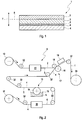
- Corresponding Fig. 1 comprises a multilayer, web-shaped filter material 1, which is suitable for the production of filter elements and for the filtration of gases and / or liquids, an at least three-layer structure, so that the filter material 1 a nonwoven layer 2, a nanofiber layer 3 and a cellulose layer 4 has.
- the nanofiber layer 3 is arranged between the nonwoven layer 2 and the cellulose layer 4.
- the nanofiber layer 3 is preferably formed by applying to the nonwoven layer 2 a coating of nanofibers. As a result, the nanofiber layer 3 is firmly connected to the nonwoven layer 2.
- the cellulose layer 4 is adhered to the nanofiber layer 3 by means of an adhesive 5, that is to say likewise fixedly connected to the nanofiber layer 3.
- the cellulose layer 4 is provided with an impregnation 6 on a side facing the nanofiber layer 3.
- the bonding of the nanofiber layer 3 to the cellulose layer 4 is effected indirectly by means of the adhesive 5, namely via the impregnation 6.
- the impregnation 6 is matched to the adhesive 5, such that the impregnation 6 prevents or at least hampers penetration of the usually applied in liquid form, not dried or uncured adhesive 5 in the cellulose layer 4.
- the adhesive 5 is made on a water basis, so that it solidifies in particular by drying.
- the impregnation 6 is then conveniently prepared on a silicone basis or formed directly by silicone.
- the nanofiber layer 3 has an in Fig. 1 indicated by an arrow thickness direction 7, which extends transversely to a web plane 8, in which the filter material 1 is located, an increasing fiber thickness and an increasing fiber density.
- an increasing fiber thickness simultaneously leads to an increasing fiber density, which in turn is accompanied by a reduction of the pore size of the nanofiber layer 3 and thus with an increased filtration effect.
- the fiber thickness increases, while the fiber density remains substantially constant, or at which the fiber density increases, while the fiber thickness remains substantially constant.
- the fiber thickness and / or the fiber density may increase in the thickness direction 7 of the filter material 1 stepless or stepped. With a stepless increase, a steady or linear increase may be preferred. In a stepped increase, two or more stages are conceivable.
- the fiber thickness or the fiber density of the nonwoven layer 2 preferably increases in the direction of the cellulose layer 4. In this case, therefore, counter to the thickness direction 7 according to Fig. 1 , A preferred throughflow direction of the filter material 1 then corresponds to the direction in which the fiber thickness or the fiber density increases. Accordingly, a preferred flow direction of the filter material 1 of the thickness direction 7 is opposite.
- a filter element not shown here can be produced, which serves for filtering gases and / or liquids and serves to filter out solid impurities.
- the respective filter element comprises at least one filter body which is produced with the aid of such a filter material 1.
- this filter body flows through the fluid to be cleaned.
- the filter material 1 is pleated in the filter body, so folded zigzag-shaped.
- the filter element is a ring filter element, which is characterized by an annular filter body, or a plate filter element, which is characterized by a plate-shaped, in particular flat, filter body.
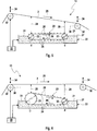
- a web-shaped nonwoven layer 2 is coated on one side with nanofibers, whereby a nanofiber layer 3 is produced directly on the nonwoven layer 2.
- the nonwoven layer 2 is unrolled from a nonwoven layer roll 10, which provides the nonwoven layer 2 quasi endless.
- a coating station 11 the one-sided coating of the nonwoven layer 2 with nanofibers takes place in order to form the nanofiber layer 3 thereon.
- the nanofiber layer 3 is respectively produced on the underside of the nonwoven layer 2.
- an adhesive 5 is applied to a sheet-like cellulose layer 4.
- the cellulose layer 4 is unrolled by a Celluloselagerolle 12, which provides the cellulose layer 4 quasi endless.
- the adhesive 5 is applied to one side of the cellulose layer 4. This can take place purely by way of example by means of a transfer roller 14, which dips into a trough 15 filled with adhesive 5 at the bottom and transfers the adhesive 5 to the cellulose layer 4 on its upper side.
- the cellulose layer 4 is impregnated before the application of the adhesive 5. This takes place in an impregnation station 16, which in a suitable manner provides the cellulose layer 4 with an impregnation 6 on the side to be provided with the adhesive 5.
- the impregnation 6 can be applied by immersing the cellulose layer 4 in an impregnating bath or by spraying the impregnating agent.
- a connecting station 17 the nonwoven layer 2 and the cellulose layer 4 are brought together, such that the adhesive 5 connects the cellulose layer 4 with the nanofiber layer 3.
- the connecting station 17 is shown here in simplified form by two rollers 18, between which the individual layers 2, 3, 4 are passed, so that the two rollers 18 roll over these layers 2, 3, 4 to each other.
- a heating station 19 can be arranged, which ensures curing or drying of the adhesive 5.
- the three-ply filter material 1 can be wound onto a filter material roll 20, which stores the web-shaped filter material 1 quasi endless.
- the coating station 11 can electrostatically apply the nanofibers to the nonwoven layer 2.
- the nonwoven layer 2 is guided at a distance from the liquid fiber material 21, which is provided for this purpose in at least one fiber delivery device 22 of the coating station 11.
- the in Fig. 3 As shown, only one such fiber delivery device 22 is provided.
- the in Fig. 4 In the embodiment shown, three such fiber delivery devices 22 are provided purely by way of example. Both FIGS. 5 and 6 on the other hand, in each case only one fiber delivery device 22 is again provided.
- the respective fiber delivery device 22 is realized here by means of a conveyor belt 23, which has a plurality of rectilinear, rod-shaped or web-shaped delivery elements 24.
- the dispensing elements 24 expediently extend over the entire width of the respective nonwoven layer 2 and extend transversely to a direction of movement 25 of the nonwoven layer 2.
- the dispensing elements 24 also extend transversely to a direction of movement 26 of the conveyor belt 23.
- the conveyor belt 23 is arranged that it dips with its underside in a trough 27, in which the liquid fiber material 21 is stored. As a result, the discharge elements 24 are immersed in the liquid fiber material 21. On its upper side, the conveyor belt 23 moves outside of the liquid fiber material 21 and faces the nonwoven layer 2.
- the dispensing elements 24 advantageously define line-shaped dispensing zones 28, which face the nonwoven layer 2 and which are spaced apart from the nonwoven layer 2. A corresponding distance is in the Fig. 3 to 6 marked and designated 29.
- the exhaust elements 24 may have a plurality of needle-shaped elevations (not shown) transversely to the direction of movement 26 of the conveyor belt 23, whereby punctiform discharge zones 28 can be realized.
- the conveyor belt 23 is clamped and driven by means of at least two rollers 33.
- the rollers 33 have in the example of Fig. 3 Same diameter d, so that the mutually moving top and bottom of the conveyor belt 23 extend parallel to each other.
- the axes of rotation of the two rollers 33 are arranged in a common plane, the extends horizontally.
- the top and the bottom of the conveyor belt 23 extend horizontally here.
- Fig. 3 shows the abovementioned distance 29 between the nonwoven layer 2 and the delivery zones 28 in the direction of movement 25 of the nonwoven layer 2 increases continuously.
- Fig. 4 shows Fig. 4 an embodiment in which the distance 29 between the nonwoven layer 2 and the respective discharge zone 28 decreases in the direction of movement 25 of the nonwoven layer 2, namely stepped.
- the nonwoven layer 2 is inclined with respect to a horizontal and planar surface 31 of the liquid fiber material 21, such that said distance 29 increases in the direction of movement 25 of the nonwoven layer 2.
- three fiber delivery devices 22 are provided purely by way of example.
- the fiber delivery devices 22 are arranged one behind the other in the direction of movement 25 of the nonwoven layer 2 and differ from one another by different spatial heights, whereby different distances 29 are established with respect to the nonwoven layer 2.
- Each fiber delivery device 22 has a conveyor belt 23 with reference to FIG Fig. 3 described type, these conveyor belts 23 in Fig. 4 however, are shown simplified; In particular, the individual delivery elements 24 and their delivery zones 28 are not shown. recognizable the distance 29 decreases in the direction of movement 25 of the nonwoven layer 2 from one fiber delivery device 22 to the next.
- a plurality of deflection rollers 32 are indicated, which deflect or align the nonwoven layer 2 or the cellulose layer 4 or the filter material 1. Visible are a front, first of the nonwoven layer 2 traversing pulley 32, in the Fig. 3 to 6 is shown on the left, and a rear, last of the nonwoven layer 2 traversed pulley 32, in the Fig. 3 to 6 is shown on the right. In Fig. 3 have the two pulleys 32 different altitudes.
- the front deflection roller 32 is arranged lower than the rear deflection roller 32, so that the nonwoven layer 2 increases in its direction of movement 25.
- the two pulleys 32 have the same altitude, so that the nonwoven layer 2 extends horizontally between the pulleys 32.
- Double arrows 34 in the deflection rollers 32 indicate that optionally at least one of the deflection rollers 32 can be arranged to be adjustable in terms of its vertical distance from the fiber delivery device 22.
- the vertical distance measured perpendicular to the horizontal can be adjusted separately for both deflection rollers 32.
- the height adjustability of at least one such deflection roller 32 can be adjusted to a slope, which has the nonwoven layer 2 between the guide rollers 32 relative to a horizontal plane 36 which in the Fig. 3 to 6 is indicated by a dot-dash line. Due to the height adjustability of at least one of the deflection rollers 32, the distances 29 between the delivery zones 28 and the nonwoven layer 2 can also be adjusted in order to optimize the coating process.
- At the in Fig. 4 embodiment shown may optionally also be provided that at least one of the guide roller 32 is arranged vertically adjustable according to the double arrows 34. Additionally or alternatively it can be provided that at least one of the fiber delivery devices 22 is arranged vertically adjustable according to double arrows 35. In this way, the distances 29 between the delivery zones 28 and the nonwoven layer 2 can be adjusted.
- Fig. 5 shows an embodiment analogous to Fig. 3 in which, however, the altitudes of the pulleys 32 are reversed. Accordingly, here the front guide roller 32 is arranged higher than the rear guide roller 32. Thus results for the nonwoven layer 2 in its direction of movement 25 a gradient. As a result, the distances 29 between the delivery zones 28 and the nonwoven layer 2 are reduced in their direction of movement 25.
- the two pulleys 32 are set to the same height again.
- an increase in the distances 29 between the delivery zones 28 and the nonwoven layer 2 in the direction of movement 25 is achieved in that the rollers 33 of the conveyor belt 23 have different diameters d and D.
- the diameter D of the left-hand roll 33 is significantly greater than the diameter d of the right-hand roll 33.
- the rolls 33 are arranged so that the underside of the conveyor belt 23 runs approximately horizontally within the fiber material 21. As a result, the upper side has a gradient in the direction of movement 25 of the nonwoven layer 2.
Description
Die vorliegende Erfindung betrifft ein mehrlagiges, bahnförmiges Filtermaterial für Filterelemente zur Filtration von Gasen und/oder Flüssigkeiten, gemäß Anspruch 1. Die Erfindung betrifft außerdem ein Filterelement, das mittels eines derartigen Filtermaterials hergestellt ist. Schließlich betrifft die vorliegende Erfindung ein Verfahren zum Herstellen eines derartigen Filtermaterials.The present invention relates to a multilayer, web-like filter material for filter elements for the filtration of gases and / or liquids, according to
Filtrationsaufgaben gibt es in vielen Bereichen der Technik. Von besonderer Bedeutung sind im Rahmen der vorliegenden Anmeldung Fahrzeuganwendungen, also Filtrationsaufgaben an bzw. in Fahrzeugen, wie zum Beispiel bei einem Luftfilter, einem Kraftstofffilter, einem Ölfilter.Filtration tasks exist in many areas of technology. For the purposes of the present application, vehicle applications, ie filtration tasks on or in vehicles, such as, for example, an air filter, a fuel filter, an oil filter, are of particular importance.
In einem Filter bzw. einer Filtereinrichtung kommen Filterelemente zum Einsatz, die jeweils zumindest einen Filterkörper aufweisen. Der Filterkörper ist dabei bevorzugt aus einem bahnförmigen Filtermaterial hergestellt, das zur Ausbildung des Filterkörpers gefaltet bzw. plissiert ist. Für eine effiziente Filtration und lange Standzeiten sind mehrlagige Filtermaterialien grundsätzlich bekannt. Zur Realisierung hoher Abscheidegrade für kleine und kleinste Verunreinigungen sind außerdem Nanofilter bekannt. Bei der Filtration existiert das allgemeine Problem, dass mit zunehmendem Filtrationsgrad auch ein Durchströmungswiderstand des Filtermaterials zunimmt. Wird beispielsweise ein besonders hoher Filtrationsgrad, insbesondere in Verbindung mit einer Nanostruktur, angestrebt, ergibt sich für das zugehörige Filtermaterial in der Regel ein sehr hoher Durchströmungswiderstand. Hohe Durchströmungswiderstände sind jedoch nachteilig, da sie zum einen das Filtermaterial mechanisch belasten und zum anderen ggf. eine angepasste Peripherie erfordern, wie zum Beispiel erhöhte Förderleistungen von Pumpen sowie verstärkte Dichtungsmaßnahmen.In a filter or a filter device filter elements are used, each having at least one filter body. The filter body is preferably made of a web-shaped filter material which is folded or pleated to form the filter body. For efficient filtration and long service lives, multilayer filter materials are generally known. Nanofilters are also known for realizing high separation rates for small and very small impurities. In filtration, there is the general problem that as the degree of filtration increases, so does a flow resistance of the filter material. If, for example, a particularly high degree of filtration, in particular in conjunction with a nanostructure, is desired, the result for the associated filter material is generally a very high flow resistance. High flow resistance, however, are disadvantageous, since they mechanically load the filter material on the one hand and, on the other hand, if necessary, an adapted one Peripherals, such as increased flow rates of pumps and reinforced sealing measures.
Ein gattungsgemäßes Filtermaterial ist aus der
Aus der
Aus der
Weitere Filtermaterialien sind beispielsweise aus der
Die vorliegende Erfindung beschäftigt sich mit dem Problem, für ein Filtermaterial bzw. für ein Filterelement bzw. für ein Herstellungsverfahren sowie für eine Herstellungsvorrichtung eine verbesserte Ausführungsform anzugeben, die sich insbesondere durch einen hohen Filtrationsgrad bei vergleichsweise geringem Durchströmungswiderstand auszeichnet.The present invention is concerned with the problem of providing an improved embodiment for a filter material or for a filter element or for a production method and for a production device, which is characterized in particular by a high degree of filtration with a comparatively low flow resistance.
Dieses Problem wird erfindungsgemäß durch die Gegenstände der unabhängigen Ansprüche gelöst. Vorteilhafte Ausführungsformen sind Gegenstand der abhängigen Ansprüche.This problem is solved according to the invention by the subject matters of the independent claims. Advantageous embodiments are the subject of the dependent claims.
Die Erfindung beruht auf dem allgemeinen Gedanken, das Filtermaterial zumindest dreilagig auszugestalten und dementsprechend zumindest mit einer Vlieslage, einer Nanofaserlage und einer Celluloselage auszustatten. Die Nanofaserlage ist dabei zwischen der Vlieslage und der Celluloselage angeordnet. Hierzu wird die Nanofaserlage durch eine Beschichtung der Vlieslage mit Nanofasern gebildet. Außerdem wird die Celluloselage mittels eines Klebestoffs mit der Nanofaserlage verklebt. Hierdurch wird ein fester Verbund zwischen den drei einzelnen Lagen realisiert, da die Nanofaserlage sowohl mit der Vlieslage als auch mit der Celluloselage fest verbunden ist. Es hat sich gezeigt, dass das so gebildete, mehrlagige Filtermaterial vom jeweiligen zu reinigenden Medium vergleichsweise geradlinig durchströmbar ist, was auf die feste Verbindung der einzelnen Lagen untereinander zurückgeführt wird. Bei lose aneinander anliegenden Lagen ist dagegen häufig eine Scherströmung zu beobachten, die sich also parallel zur Ebene der jeweiligen Lage orientiert. Derartige Scherströmungen werden beim hier vorgestellten Filtermaterial weitgehend vermieden, so dass die einzelnen Lagen weitgehend quer zu ihrer Ebene durchströmt werden, also im Wesentlichen nur in ihrer Dickenrichtung. Hierdurch lässt sich der Durchströmungswiderstand signifikant reduzieren.The invention is based on the general idea to design the filter material at least three layers and accordingly equip at least with a nonwoven layer, a nanofiber layer and a cellulose layer. The nanofiber layer is arranged between the nonwoven layer and the cellulose layer. For this purpose, the nanofiber layer is formed by coating the nonwoven layer with nanofibers. In addition, the cellulose layer is bonded by means of an adhesive with the nanofiber layer. As a result, a solid bond between the three individual layers is realized, since the nanofiber layer is firmly bonded both to the nonwoven layer and to the cellulose layer. It has been shown that the thus formed, multi-layer filter material from the respective medium to be cleaned can be flowed through relatively straightforward, which is attributed to the solid connection of the individual layers with each other. For loosely adjacent layers, however, a shear flow is often observed, which is thus oriented parallel to the plane of the respective layer. Such shear flows are largely avoided in the filter material presented here, so that the individual layers are largely traversed transversely to their plane, ie substantially only in their thickness direction. As a result, the flow resistance can be significantly reduced.
Erfindungsgemäß ist die Celluloselage an einer der Nanofaserlage zugewandten Seite mit einer Imprägnierung versehen sein. Durch diese Imprägnierung wird erreicht, dass der Klebstoff zwar eine feste Verbindung zwischen der Nanofaserlage und der Celluloselage herstellen kann, jedoch nicht so weit in die Celluloselage eindringen kann, dass er dadurch die Poren der Celluloselage verschließt.According to the invention, the cellulose layer is provided with an impregnation on a side facing the nanofiber layer. By means of this impregnation it is achieved that the adhesive can indeed establish a firm bond between the nanofiber layer and the cellulose layer, but can not penetrate into the cellulose layer so far that it thereby seals the pores of the cellulose layer.
Erfindungsgemäß ist die Imprägnierung auf den Klebstoff abgestimmt, derart, dass die Imprägnierung gezielt ein Eindringen des Klebstoffs in die Celluloselage verhindert oder zumindest behindert.According to the invention, the impregnation is adapted to the adhesive, such that the impregnation specifically prevents or at least impedes the penetration of the adhesive into the cellulose layer.
Gemäß einer anderen vorteilhaften Ausführungsform kann der Klebstoff auf einer Wasserbasis hergestellt sein. Derartige Klebstoffe zeichnen sich durch eine relativ hohe Umweltverträglichkeit aus. Insbesondere kann dadurch auch ein Recycling des Filtermaterials vereinfacht werden.According to another advantageous embodiment, the adhesive may be made on a water basis. Such adhesives are characterized by a relatively high environmental impact. In particular, this can also be a recycling of the filter material can be simplified.
Bei einer anderen vorteilhaften Ausführungsform kann vorgesehen sein, die Imprägnierung auf einer Silikonbasis herzustellen oder durch Silikon zu bilden. Eine derartige Imprägnierung wirkt stark hydrophob und kann dadurch eine Benetzung der Celluloselage mit Wasser bzw. mit einem wasserbasierten Klebstoff behindern.In another advantageous embodiment it can be provided to produce the impregnation on a silicone basis or to form it by silicone. Such impregnation has a strong hydrophobic effect and can hinder wetting of the cellulose layer with water or with a water-based adhesive.
Bei einer anderen vorteilhaften Ausführungsform kann die Nanofaserlage in einer Dickenrichtung des Filtermaterials eine zunehmende Faserdicke und/oder eine zunehmende Faserdichte aufweisen. Es hat sich gezeigt, dass auch eine derartige Ausführungsform zu einem reduzierten Durchströmungswiderstand führen kann, wobei gleichzeitig ein hoher Filtrationsgrad realisierbar ist. Die Faserdicke und die Faserdichte beeinflussen signifikant den Filtrationsgrad sowie den Durchströmungswiderstand. Durch die hier vorgeschlagene Graduierung der Faserdicke und/oder der Faserdichte wird somit auch die Filtrationswirkung graduiert. Dies führt dazu, dass grobe Verunreinigungen in einem Bereich niedriger Filtration zurückgehalten werden, während kleinere Verunreinigungen tiefer in das Filtermaterial eindringen können und darin in einem Bereich mit höherem Filtrationsgrad aufgehalten werden. Im Vergleich zu einem herkömmlichen Filtermaterial, dessen Nanofasern in der Dickenrichtung hinsichtlich Faserdicke und Faserdichte kontinuierlich gefertigt sind, kann durch die vorgeschlagene Graduierung, bei gleichem Filtrationsgrad ein reduzierter Durchströmungswiderstand realisiert werden. Dies wird damit erklärt, dass bei einer herkömmlichen Nanofaserstruktur sowohl die groben als auch die kleinen Verunreinigungen bereits außen an der Nanofaserstruktur abgeschieden werden.In another advantageous embodiment, the nanofiber layer can have an increasing fiber thickness and / or an increasing fiber density in a thickness direction of the filter material. It has been found that even such an embodiment can lead to a reduced flow resistance, wherein at the same time a high degree of filtration can be realized. The fiber thickness and the fiber density significantly affect the degree of filtration and the flow resistance. By the here proposed graduation of the fiber thickness and / or the fiber density thus the filtration effect is also graduated. As a result, coarse contaminants are retained in a region of low filtration, while smaller contaminants can penetrate deeper into the filter material and become trapped therein in a region of higher filtration. Compared to a conventional filter material, whose nanofibers are continuously made in the thickness direction in terms of fiber thickness and fiber density, the proposed graduation, with the same degree of filtration a reduced flow resistance can be realized. This is explained by the fact that in a conventional nanofiber structure, both the coarse and the small impurities are already deposited on the outside of the nanofiber structure.
Entsprechend einer vorteilhaften Weiterbildung können die Faserdicke und/oder die Faserdichte in der Dickenrichtung des Filtermaterials stufenlos, vorzugsweise gleichmäßig, oder gestuft zunehmen. Zusätzlich oder alternativ kann vorgesehen sein, dass die Faserdicke und/oder die Faserdichte von der Vlieslage zur Celluloselage hin zunimmt. Zweckmäßig kann innerhalb der Nanofaserlage die Faserdicke von 100 nm bis 800 nm variieren.According to an advantageous development, the fiber thickness and / or the fiber density in the thickness direction of the filter material can increase continuously, preferably uniformly or stepped. Additionally or alternatively it can be provided that the fiber thickness and / or the fiber density increases from the nonwoven layer to the cellulose layer. Suitably, within the nanofiber layer, the fiber thickness can vary from 100 nm to 800 nm.
Ein erfindungsgemäßes Filterelement zum Filtern von Gasen und/oder Flüssigkeiten umfasst zumindest einen Filterkörper, der im Betrieb des Filterelements von einem Strom aus Gas und/oder Flüssigkeit durchströmt ist, wobei der jeweilige Filterkörper ein Filtermaterial der vorstehend beschriebenen Art aufweist.A filter element according to the invention for filtering gases and / or liquids comprises at least one filter body which flows through a stream of gas and / or liquid during operation of the filter element, the respective filter body having a filter material of the type described above.
Zur Vergrößerung der durchströmbaren Filterfläche kann das Filtermaterial zweckmäßig plissiert also gefaltet sein.To increase the filter surface which can be flowed through, the filter material can be suitably pleated, ie folded.
Entsprechend einer anderen Ausführungsform kann das Filterelement ein Ringfilterelement mit ringförmigem Filterkörper oder ein Plattenfilterelement mit plattenförmigem Filterkörper sein.According to another embodiment, the filter element may be a ring filter element with an annular filter body or a plate filter element with a plate-shaped filter body.
Ein erfindungsgemäßes Herstellungsverfahren, mit dem ein mehrlagiges, bahnförmiges Filtermaterial, insbesondere der vorstehend beschriebenen Art, hergestellt werden kann, charakterisiert sich dadurch, dass eine bahnförmige Vlieslage einseitig mit Nanofasern beschichtet wird, um unmittelbar an der Vlieslage eine Nanofaserlage zu erzeugen. Ferner wird auf eine Celluloselage zumindest einseitig ein Klebstoff aufgebracht. Schließlich werden die Celluloselage und die Vlieslage zusammengeführt, derart, dass der Klebstoff die Celluloselage mit der Nanofaserlage verbindet. Die Celluloselage ist vor dem Aufbringen des Klebstoffs einseitig mit einer Imprägnierung zu versehen.A production method according to the invention with which a multilayer, web-shaped filter material, in particular of the type described above, can be produced, is characterized in that a web-like nonwoven layer is coated on one side with nanofibers in order to produce a nanofiber layer directly on the nonwoven layer. Furthermore, an adhesive is applied to a cellulose layer at least on one side. Finally, the cellulosic layer and the nonwoven layer are brought together such that the adhesive bonds the cellulose layer to the nanofiber layer. The cellulose layer must be impregnated on one side before application of the adhesive.
Die Nanofasern können entsprechend einer vorteilhaften Ausführungsform in einer Beschichtungsstation auf die Vlieslage elektrostatisch aufgebracht werden, wobei in einer Faserabgabeeinrichtung dieser Beschichtungsstation zwischen dem flüssigen Fasermateral und der Vlieslage ein Abstand besteht. Es erfolgt somit keine unmittelbare Kontaktierung, zwischen der Vlieslage und dem flüssigen Fasermaterial. Insbesondere kommt es zu keinem Eintauchen der Vlieslage in das flüssige Fasermaterial. Vielmehr wird die Vlieslage beabstandet am flüssigen Fasermaterial vorbeigeführt. Mittels elektrostatischer Ladung können zwischen dem flüssigen Fasermaterial und der Vlieslage Ionenströme erzeugt werden, die das Fasermaterial molekülweise auf die Vlieslage transportieren. Damit sich die Moleküle des Fasermaterials aus dem flüssigen Fasermaterial besser ablösen und über den Ionenstrom zur Vlieslage gelangen können, ist es zweckmäßig, innerhalb der Faserabgabeeinrichtung eine linienförmige oder punktförmige Oberfläche für das flüssige Fasermaterial zu schaffen, um dort besonders hohe elektrostatische Spannungen erzeugen zu können. Dies kann beispielsweise dadurch erfolgen, dass eine Walze an ihrer Unterseite in das flüssige Fasermaterial eintaucht und an ihrer Oberseite der Vlieslage zugewandt ist. Besonders vorteilhaft ist jedoch eine Ausführungsform, bei welcher die Faserabgabeeinrichtung durch eine Art Förderband gebildet ist, das mehrere stabförmige Abgabeelemente aufweist, die in der Bewegungsrichtung des Förderbands hintereinander angeordnet sind und in der Bewegungsrichtung des Förderbands voneinander beabstandet sind. Das Förderband taucht an seiner Unterseite in das flüssige Fasermaterial ein und ist an seiner Oberseite der Vlieslage zugewandt. Die stabförmigen Abgabeelemente werden durch die Bewegung des Förderbands in das Fasermaterial eingetaucht und dabei mit Fasermaterial getränkt, das sie dann an der anderen Seite über eine linienförmige oder punktförmige Abgabezone mit Hilfe der Elektrostatik bzw. mit Hilfe der Ionenströme an die Vlieslage abgeben können.According to an advantageous embodiment, the nanofibers can be electrostatically applied to the nonwoven layer in a coating station, wherein there is a spacing between the liquid fiber side and the nonwoven layer in a fiber delivery device of this coating station. There is thus no direct contact, between the nonwoven layer and the liquid fiber material. In particular, there is no immersion of the nonwoven layer in the liquid fiber material. Rather, the nonwoven layer is guided past the liquid fiber material at a distance. By means of electrostatic charge ion streams can be generated between the liquid fiber material and the nonwoven layer, which transport the fiber material molecule by molecule on the nonwoven layer. In order for the molecules of the fiber material to detach better from the liquid fiber material and to reach the nonwoven layer via the ion current, it is expedient to create a linear or punctiform surface for the liquid fiber material within the fiber delivery device in order to be able to generate particularly high electrostatic stresses there. This can be done, for example, by immersing a roller on its underside in the liquid fiber material and facing the nonwoven layer on its upper side. However, particularly advantageous is an embodiment in which the fiber delivery device is formed by a kind of conveyor belt having a plurality of rod-shaped discharge elements, which are arranged one behind the other in the direction of movement of the conveyor belt and spaced apart in the direction of movement of the conveyor belt. The conveyor belt dives on its underside into the liquid fiber material and faces the nonwoven layer on its upper side. The rod-shaped discharge elements are immersed by the movement of the conveyor belt in the fiber material and thereby impregnated with fiber material, which they then on the other side via a line-shaped or point-shaped discharge zone using the electrostatics or with the help of the ion currents can deliver to the nonwoven layer.
Entsprechend einer vorteilhaften Weiterbildung kann der Abstand in der Bewegungsrichtung der Vlieslage zunehmen oder abnehmen. Es hat sich gezeigt, dass der Abstand zwischen Vlieslage und der jeweiligen, das Fasermaterial abgebenden Oberfläche bzw. Zone, die bevorzugt linienförmig oder punktförmig ausgestaltet ist, entscheidend ist für die realisierbare Faserdicke und/oder Faserdichte. Durch Verändern des Abstands in der Bewegungsrichtung kann somit die Faserdicke und/oder die Faserdichte beeinflusst werden.According to an advantageous development of the distance in the direction of movement of the nonwoven layer increase or decrease. It has been found that the distance between the nonwoven layer and the respective surface or zone which gives off the fiber material, which is preferably configured in the form of a line or dot, is decisive for the achievable fiber thickness and / or fiber density. By varying the distance in the direction of movement, the fiber thickness and / or the fiber density can thus be influenced.
Bei einer anderen Ausführungsform kann die Vlieslage mit einer Neigung gegenüber einer horizontalen und ebenen Oberfläche des Fasermaterials vorbeibewegt werden. Hierdurch wird ein kontinuierlich abnehmender bzw. kontinuierlich zunehmender Abstand zwischen Vlieslage und Fasermaterial erreicht. Zum Einstellen der Abstände kann optional vorgesehen sein, dass eine Neidung der Vlieslage gegenüber einer Horizontalebene einstellbar ist.In another embodiment, the nonwoven layer may be moved past with a slope relative to a horizontal and planar surface of the fibrous material. As a result, a continuously decreasing or continuously increasing distance between the nonwoven layer and the fiber material is achieved. To set the distances may optionally be provided that a Neidung the nonwoven layer relative to a horizontal plane is adjustable.
Bei einer anderen Ausführungsform können mehrere Faserabgabeeinrichtungen in der Bewegungsrichtung der Vlieslage hintereinander vorgesehen sein, in denen verschiedene Abstände zwischen dem Fasermaterial und der Vlieslage bestehen. Dabei kann grundsätzlich jede einzelne Faserabgabeeinrichtung gemäß der vorstehend beschriebenen Art als Förderband konfiguriert sein. Die einzelnen Faserabgabeeinrichtungen können d 7a tional höhenverstellbar sein, um die Abstände einstellen zu können.In another embodiment, a plurality of fiber delivery devices may be provided in succession in the direction of movement of the nonwoven layer, in which different distances between the fiber material and the nonwoven layer exist. In principle, each individual fiber delivery device can be configured as a conveyor belt in the manner described above. The individual fiber delivery devices can be vertically adjustable in order to be able to adjust the distances.
Die Vlieslage kann auch als "non-woven" oder als "blow-melt" bezeichnet werden.The nonwoven layer can also be referred to as "non-woven" or as "blow-melt".
Eine Vorrichtung zum Herstellen eines Filtermaterials, insbesondere der vorstehend beschriebenen Art, umfasst wenigstens eine Faserabgabeeinrichtung, die ein Förderband mit wenigstens zwei Walzen und eine mit flüssigem Fasermaterial befüllbare Wanne aufweist, in welche das Förderband zumindest an einer Unterseite eintaucht, wenigstens zwei Umlenkrollen zum Führen einer Vlieslage oberhalb der Faserabgabeeinrichtung und beabstandet zu einer Oberseite des Förderbands und eine lonisierungseinrichtung zum Erzeugen unterschiedlicher elektrischer Potentiale an der Vlieslage und an der Faserabgabeeinrichtung, derart, dass im Betrieb der Vorrichtung flüssiges Fasermaterial elektrostatisch vom Förderband zur Vlieslage transportiert wird. Es hat sich gezeigt, dass mit einer derartigen Vorrichtung eine Nanofaserschicht besonders einfach
und mit reproduzierbaren Parametern wie Dichte und Dicke auf die Vlieslage auftragen lässt.A device for producing a filter material, in particular of the type described above, comprises at least one fiber delivery device comprising a conveyor belt with at least two rollers and a tank filled with liquid fiber material, into which the conveyor belt dips at least on one underside, at least two deflection rollers for guiding one Nonwoven layer above the fiber delivery device and spaced from an upper side of the conveyor belt and an ionization device for generating different electrical potentials at the nonwoven layer and at the fiber delivery device, such that liquid fiber material is electrostatically transported from the conveyor belt to the nonwoven layer during operation of the device. It has been found that with such a device, a nanofiber layer is particularly simple
and can be applied to the nonwoven layer with reproducible parameters such as density and thickness.
Gemäß einer vorteilhaften Ausführungsform kann die Vorrichtung so ausgestaltet sein, dass ein Abstand zwischen der Vlieslage und der jeweiligen Oberseite des Förderbands in der Bewegungsrichtung der Vlieslage variiert. Hierdurch lässt sich eine graduierte Beschichtung, also eine Beschichtung mit in der Dickenrichtung variierender Dichte auf die Vlieslage aufbringen.According to an advantageous embodiment, the device can be designed such that a distance between the nonwoven layer and the respective upper side of the conveyor belt varies in the direction of movement of the nonwoven layer. As a result, a graduated coating, that is to say a coating with a density varying in the thickness direction, can be applied to the nonwoven layer.
Vorteilhaft kann besagter Abstand z.B. dadurch eingestellt werden, dass wenigstens eine der Umlenkrollen höhenverstellbar angeordnet ist. Zusätzlich oder alternativ kann vorgesehen sein, dass wenigstens eine solche Faserabgabeeinrichtung höhenverstellbar angeordnet ist.Advantageously, said distance may e.g. be adjusted by that at least one of the deflection rollers is arranged vertically adjustable. Additionally or alternatively it can be provided that at least one such fiber delivery device is arranged vertically adjustable.
Ein variierender Abstand lässt sich auch dadurch realisieren, dass die Walzen so angeordnet sind, dass die Oberseite des Förderbands gegenüber einer Horizontalebene geneigt verläuft. Hierzu können die Walzen verschiedene Durchmesser besitzen und/oder auf verschiedenen Höhenlagen angeordnet sein, so dass sie unterschiedlich tief in die Wanne eintauchen.A varying distance can also be realized in that the rollers are arranged so that the top of the conveyor belt is inclined relative to a horizontal plane. For this purpose, the rollers may have different diameters and / or be arranged at different altitudes, so that they dive at different depths in the tub.
Weitere wichtige Merkmale und Vorteile der Erfindung ergeben sich aus den Unteransprüchen, aus den Zeichnungen und aus der zugehörigen Figurenbeschreibung anhand der Zeichnungen.Other important features and advantages of the invention will become apparent from the dependent claims, from the drawings and from the associated figure description with reference to the drawings.
Es versteht sich, dass die vorstehend genannten und die nachstehend noch zu erläuternden Merkmale nicht nur in der jeweils angegebenen Kombination, sondern auch in anderen Kombinationen oder in Alleinstellung verwendbar sind, ohne den Rahmen der vorliegenden Erfindung zu verlassen.It is understood that the features mentioned above and those yet to be explained below can be used not only in the particular combination given, but also in other combinations or in isolation, without departing from the scope of the present invention.
Bevorzugte Ausführungsbeispiele der Erfindung sind in den Zeichnungen dargestellt und werden in der nachfolgenden Beschreibung näher erläutert, wobei sich gleiche Bezugszeichen auf gleiche oder ähnliche oder funktional gleiche Komponenten beziehen.Preferred embodiments of the invention are illustrated in the drawings and will be described in more detail in the following description, wherein like reference numerals refer to the same or similar or functionally identical components.
Es zeigen, jeweils schematisch,
- Fig. 1
- eine stark vereinfachte Schnittansicht eines Filtermaterials,
- Fig. 2
- eine stark vereinfachte Prinzipdarstellung einer Vorrichtung zum Herstellen von Filtermaterial,
- Fig. 3
- eine stark vereinfachte Prinzipdarstellung einer Beschichtungsstation,
- Fig. 4-6
- Ansichten wie in
Fig. 3 , jedoch bei anderen Ausführungsformen der Beschichtungsstation.
- Fig. 1
- a highly simplified sectional view of a filter material,
- Fig. 2
- a greatly simplified schematic diagram of an apparatus for producing filter material,
- Fig. 3
- a simplified schematic diagram of a coating station,
- Fig. 4-6
- Views like in
Fig. 3 but in other embodiments of the coating station.
Entsprechend
Somit erfolgt die Verklebung der Nanofaserlage 3 mit der Celluloselage 4 mittels des Klebstoffs 5 mittelbar, nämlich über die Imprägnierung 6.Thus, the bonding of the
Die Imprägnierung 6 ist auf den Klebstoff 5 abgestimmt, derart, dass die Imprägnierung 6 ein Eindringen des üblicherweise in flüssiger Form aufgebrachten, nicht getrockneten bzw. nicht ausgehärteten Klebstoffs 5 in die Celluloselage 4 verhindert oder zumindest behindert. Beispielsweise ist der Klebstoff 5 auf einer Wasserbasis hergestellt, so dass er sich insbesondere durch Trocknung verfestigt. Die Imprägnierung 6 ist dann zweckmäßig auf einer Silikonbasis hergestellt oder unmittelbar durch Silikon gebildet.The
Die Nanofaserlage 3 weist in einer in
Die Faserdicke und/oder die Faserdichte können in der Dickenrichtung 7 des Filtermaterials 1 stufenlos oder gestuft zunehmen. Bei einer stufenlosen Zunahme kann eine gleichmäßige oder lineare Zunahme bevorzugt sein. Bei einer gestuften Zunahme sind zwei oder mehr Stufen denkbar.The fiber thickness and / or the fiber density may increase in the
Vorzugsweise nimmt die Faserdicke bzw. die Faserdichte von der Vlieslage 2 in Richtung zur Celluloselage 4 zu. In diesem Fall also entgegen der Dickenrichtung 7 gemäß
Mit Hilfe des hier gezeigten Filtermaterials 1 lässt sich ein hier nicht gezeigtes Filterelement herstellen, das zum Filtern von Gasen und/oder Flüssigkeiten dient und zum Herausfiltern von festen Verunreinigungen dient. Hierzu umfasst das jeweilige Filterelement zumindest einen Filterkörper, der mit Hilfe eines derartigen Filtermaterials 1 hergestellt ist. Im Betrieb des Filterelements ist dieser Filterkörper von dem zu reinigenden Fluid durchströmt. Zweckmäßig ist das Filtermaterial 1 im Filterkörper plissiert, also zick-zack-förmig gefaltet. Bei bevorzugten Ausführungsformen handelt es sich beim Filterelement um ein Ringfilterelement, das sich durch einen ringförmigen Filterkörper auszeichnet, oder um ein Plattenfilterelement, das sich durch einen plattenförmigen, insbesondere ebenen, Filterkörper auszeichnet.With the aid of the
Nachfolgend wird anhand der
Im Rahmen des Herstellungsverfahrens wird eine bahnförmige Vlieslage 2 einseitig mit Nanofasern beschichtet, wodurch unmittelbar an der Vlieslage 2 eine Nanofaserlage 3 erzeugt wird. Hierzu wird die Vlieslage 2 von einer Vlieslagenrolle 10 abgerollt, welche die Vlieslage 2 quasi endlos bereitstellt. In einer Beschichtungsstation 11 erfolgt die einseitige Beschichtung der Vlieslage 2 mit Nanofasern, um daran die Nanofaserlage 3 auszubilden. In den
Des Weiteren wird in der Vorrichtung 9 auf eine bahnförmige Celluloselage 4 ein Klebstoff 5 aufgebracht. Hierzu wird die Celluloselage 4 von einer Celluloselagerolle 12 abgerollt, welche die Celluloselage 4 quasi endlos bereitstellt. In einer Klebstoffaufbringstation 13 wird der Klebstoff 5 auf eine Seite der Celluloselage 4 aufgebracht. Dies kann rein exemplarisch mittels einer Transferwalze 14 erfolgen, die unten in eine mit Klebstoff 5 gefüllte Wanne 15 eintaucht und an ihrer Oberseite den Klebstoff 5 auf die Celluloselage 4 überträgt. Die Celluloselage 4 wird vor dem Aufbringen des Klebstoffs 5 imprägniert. Dies erfolgt in einer Imprägnierstation 16, die auf geeignete Weise die Celluloselage 4 an der mit dem Klebstoff 5 zu versehenden Seite mit einer Imprägnierung 6 versieht. Das Aufbringen der Imprägnierung 6 kann durch Eintauchen der Celluloselage 4 in ein Imprägniermittelbad oder durch Aufsprühen des Imprägniermittels erfolgen.Furthermore, in the
In einer Verbindungsstation 17 werden die Vlieslage 2 und die Celluloselage 4 zusammengeführt, derart, dass der Klebstoff 5 die Celluloselage 4 mit der Nanofaserlage 3 verbindet. Die Verbindungsstation 17 ist hier vereinfacht durch zwei Walzen 18 wiedergegeben, zwischen denen die einzelnen Lagen 2, 3, 4 hindurchgeführt sind, so dass die beiden Walzen 18 über diese Lagen 2, 3, 4 aneinander abrollen. Nach der Verbindungsstation 17 kann eine Heizstation 19 angeordnet sein, die für ein Aushärten bzw. Trocknen des Klebstoffs 5 sorgt. Anschließend kann das dreilagige Filtermaterial 1 auf eine Filtermaterialrolle 20 aufgewickelt werden, die das bahnförmige Filtermaterial 1 quasi endlos bevorratet. Gemäß den
Die jeweilige Faserabgabeeinrichtung 22 ist hier mit Hilfe eines Förderbands 23 realisiert, das mehrere geradlinige, stabförmige oder stegförmige Abgabeelemente 24 aufweist. Die Abgabeelemente 24 erstrecken sich zweckmäßig über die gesamte Breite der jeweiligen Vlieslage 2 und erstrecken sich dabei quer zu einer Bewegungsrichtung 25 der Vlieslage 2. Die Abgabeelemente 24 erstrecken sich dabei auch quer zu einer Bewegungsrichtung 26 des Förderbands 23. Das Förderband 23 ist so angeordnet, dass es mit seiner Unterseite in eine Wanne 27 eintaucht, in der das flüssige Fasermaterial 21 bevorratet ist. Hierdurch werden die Abgabeelemente 24 in das flüssige Fasermaterial 21 eingetaucht. An seiner Oberseite bewegt sich das Förderband 23 außerhalb des flüssigen Fasermaterials 21 und ist der Vlieslage 2 zugewandt. Die Abgabeelemente 24 definieren zweckmäßig linienförmige Abgabezonen 28, die der Vlieslage 2 zugewandt sind und die zur Vlieslage 2 beabstandet sind. Ein entsprechender Abstand ist in den
Das Förderband 23 ist mittels wenigstens zwei Walzen 33 aufgespannt und angetrieben. Die Walzen 33 besitzen im Beispiel der
Mit Hilfe einer lonisierungseinrichtung 30 lassen sich unterschiedliche elektrische Potentiale an der Vlieslage 2 und an der Faserabgabeeinrichtung 22 generieren, wodurch eine elektrostatische Aufladung realisiert wird, die letztlich zu einem Ionenstrom führt, der Moleküle des Fasermaterials 21 von den Abgabezonen 28 abführt, in Richtung Vlieslage 2 transportiert und an der Vlieslage 2 anhaften lässt.With the help of an
Bei der in
In
In den
Im Beispiel der
Doppelpfeile 34 bei den Umlenkrollen 32 deuten an, dass optional wenigstens eine der Umlenkrollen 32 hinsichtlich ihres Vertikalabstands von der Faserabgabeeinrichtung 22 einstellbar angeordnet sein kann. Bevorzugt lässt sich der senkrecht zur Horizontalen gemessene Vertikalabstand bei beiden Umlenkrollen 32 separat einstellen. Die Höhenverstellbarkeit wenigstens einer solchen Umlenkrolle 32 lässt sich eine Neigung einstellen, welche die Vlieslage 2 zwischen den Umlenkrollen 32 gegenüber einer Horizontalebene 36 besitzt, die in den
Bei der in
Bei der in
Es ist klar, dass die hier in Verbindung mit den
Claims (14)
- A multi-layered, web-shaped filter material (1) for filter elements for the filtration of gases and/or liquids,- with a fleece layer (2),- with a nanofibre layer (3),- with a cellulose layer (4),- wherein the nanofibre layer (3) is formed through a coating of the fleece layer (2) with nanofibres,- wherein the cellulose layer (4) is glued onto the nanofibre layer (3) by means of an adhesive (5),characterized in- that the cellulose layer (4) at least on a side facing the nanofibre layer (3) is provided with an impregnation (6),- that the impregnation (6) is matched to the adhesive (5) so that it prevents or at least impedes the adhesive (5) entering the cellulose layer (4).
- The filter material according to Claim 1,
Characterized in- that the adhesive (5) is produced on a water base, and/or- that the impregnation (6) is produced on a silicone base or consists of silicone. - The filter material according to Claim 1 or 2,
characterized in
that the nanofibre layer (3) in a thickness direction (7) of the filter material (1) has an increasing fibre thickness and/or an increasing fibre density. - The filter material according to Claim 3,
characterized in
that the fibre thickness and/or the fibre density in the thickness direction (7) of the filter material (1) increases steplessly, preferentially evenly, or in steps. - The filter material according to Claim 3 or 4,
characterized in
that the fibre thickness and/or the fibre density increase/increases from the fleece layer (2) to the cellulose layer (4). - A filter element for filtering gases and/or liquids with at least one filter body, which during the operation of the filter element is subjected to a through-flow of gas and/or liquid, wherein the respective filter body has a filter material (1) according to any one of the Claims 1 to 5.
- The filter element according to Claim 6,
characterized in
that the filter material (1) is pleated. - The filter element according to Claim 6 or 7,
characterized in
that the filter element is a ring filter element with a ring-shaped filter body or a plate filter element with a plate-shaped filter body. - A method for producing a multi-layered, web-shaped filter material (1), in particular according to any one of the Claims 1 to 6- in which a web-shaped fleece layer (2) is coated with nanofibres on one side, in order to generate a nanofibre layer (3) directly on the fleece layer (2),- in which an adhesive (5) is applied onto a web-shaped cellulose layer (4),- in which the cellulose layer (4) and the fleece layer (2) are brought together so that the adhesive (5) connects the cellulose layer (4) to the nanofibre layer (3),characterized in
that the cellulose layer (4) prior to applying the adhesive (5) is provided with an impregnation (6) at least on one side, wherein the adhesive is applied onto the impregnated side of the cellulose layer (4), wherein the impregnation (6) is matched to the adhesive (5) so that it prevents or at least impedes the adhesive (5) entering the cellulose layer (4). - The method according to Claim 9,
characterized in
that the nanofibres are electrostatically applied onto the fleece layer (2) in a coating station (11), wherein in a fibre dispensing device (22) of the coating station (11) there is a spacing (29) between the liquid fibre material (21) and the fleece layer (2). - The method according to Claim 10,
characterized in
that the spacing (29) increases or decreases in the movement direction (25) of the fleece layer (2). - The method according to Claim 10 or 11,
characterized in
that the fleece layer (2) is moved past the horizontal and flat surface (31) of the fibre material (21) with an inclination. - The method according to any one of the Claims 10 to 12,
characterized in
that a plurality of fibre dispensing devices (22) are provided in the movement direction (25) of the fleece layer (2) one after the other, in which there are different spacings (29) between the fibre material (21) and the fleece layer (2). - The method according to one of Claims 10 to 13,
characterized in that
for altering the spacing (29) or respectively the spacings (29), an inclination of the fleece layer (2) is adjusted with respect to a horizontal plane (36).
Applications Claiming Priority (3)
| Application Number | Priority Date | Filing Date | Title |
|---|---|---|---|
| IN2552DE2013 | 2013-08-29 | ||
| DE201310221341 DE102013221341A1 (en) | 2013-10-21 | 2013-10-21 | Filter material, filter element and manufacturing process |
| PCT/EP2014/068213 WO2015028530A2 (en) | 2013-08-29 | 2014-08-28 | Filter material, filter element, and a method and device for producing a filter material |
Publications (2)
| Publication Number | Publication Date |
|---|---|
| EP3038732A2 EP3038732A2 (en) | 2016-07-06 |
| EP3038732B1 true EP3038732B1 (en) | 2018-02-28 |
Family
ID=51422080
Family Applications (1)
| Application Number | Title | Priority Date | Filing Date |
|---|---|---|---|
| EP14756048.6A Not-in-force EP3038732B1 (en) | 2013-08-29 | 2014-08-28 | Filter material, filter element, and a method for producing a filter material |
Country Status (3)
| Country | Link |
|---|---|
| US (1) | US9624605B2 (en) |
| EP (1) | EP3038732B1 (en) |
| WO (1) | WO2015028530A2 (en) |
Families Citing this family (4)
| Publication number | Priority date | Publication date | Assignee | Title |
|---|---|---|---|---|
| US10744461B2 (en) | 2016-08-02 | 2020-08-18 | Washington University | Ultrafiltration membrane based on bacterial nanocellulose and graphene oxide |
| US10729988B2 (en) * | 2016-08-02 | 2020-08-04 | Washington University | Bilayered structures for solar steam generation |
| CN108105098A (en) * | 2016-11-25 | 2018-06-01 | 曼胡默尔滤清器(上海)有限公司 | A kind of efficient tank-type separator for separation oil and gas mixture |
| KR20210074346A (en) * | 2018-10-19 | 2021-06-21 | 클라우스 고트샬 | Filtration Media, Materials and Methods for Contaminant Removal |
Citations (3)
| Publication number | Priority date | Publication date | Assignee | Title |
|---|---|---|---|---|
| EP1366791A1 (en) * | 2002-05-28 | 2003-12-03 | Hollingsworth & Vose GmbH & Co. KG | Filter material |
| EP2183414A2 (en) * | 2007-08-01 | 2010-05-12 | Donaldson Company, Inc. | Fluoropolymer fine fiber |
| WO2013068436A1 (en) * | 2011-11-10 | 2013-05-16 | Mahle International Gmbh | Filter material |
Family Cites Families (23)
| Publication number | Priority date | Publication date | Assignee | Title |
|---|---|---|---|---|
| DE2620399C3 (en) | 1976-05-08 | 1980-11-13 | Fa. Carl Freudenberg, 6940 Weinheim | Device for electrostatic spraying |
| US5350443B2 (en) * | 1993-04-19 | 1999-08-10 | Von Hasso Bluecher | Filter sheet material for passenger cabins in motor vehicles |
| US5800586A (en) | 1996-11-08 | 1998-09-01 | Johns Manville International, Inc. | Composite filter media |
| IL132945A0 (en) | 1999-06-07 | 2001-03-19 | Nicast Ltd | Filtering material and device and method of its manufacture |
| DE20207663U1 (en) | 2002-05-16 | 2002-09-12 | Branofilter Gmbh | Multi-layer filter construction |
| WO2004069378A2 (en) | 2003-02-05 | 2004-08-19 | Helsa-Werke Helmut Sandler Gmbh & Co. Kg | Filter element and method for the production thereof |
| CZ294274B6 (en) * | 2003-09-08 | 2004-11-10 | Technická univerzita v Liberci | Process for producing nanofibers from polymeric solution by electrostatic spinning and apparatus for making the same |
| US20050217625A1 (en) * | 2004-04-05 | 2005-10-06 | Advanced Flow Engineering, Inc. | Heat shielded air intake system |
| US8092566B2 (en) * | 2004-12-28 | 2012-01-10 | E.I. Du Pont De Nemours And Company | Filtration media for filtering particulate material from gas streams |
| CZ305244B6 (en) * | 2005-11-10 | 2015-07-01 | Elmarco S.R.O. | Process for producing nanofibers by electrostatic spinning of solutions or melts of polymers and apparatus for making the same |
| US8202340B2 (en) | 2007-02-28 | 2012-06-19 | Hollingsworth & Vose Company | Waved filter media and elements |
| GB0704615D0 (en) * | 2007-03-09 | 2007-04-18 | Univ Gent | A process for the preparation of highly porous nanofibrous structures and a device for preparing as such |
| CA2687563A1 (en) * | 2007-05-18 | 2008-11-27 | Universiteit Gent | Production and use of laminated nanofibrous structures |
| DE102007027299B4 (en) | 2007-06-11 | 2009-02-26 | Johns Manville Europe Gmbh | Filter, process for its production, its use and filter modules |
| CZ300345B6 (en) | 2007-07-17 | 2009-04-22 | Elmarco, S. R. O. | Method for spinning the liquid matrix, device for production of nanofibers through electrostatic spinning of liquid matrix and spinning electrode for such device |
| DE202007011447U1 (en) | 2007-08-16 | 2007-10-11 | Wolf Gmbh & Co. Kg | filter media |
| US7967588B2 (en) * | 2007-11-20 | 2011-06-28 | Clarcor Inc. | Fine fiber electro-spinning equipment, filter media systems and methods |
| CN102016150A (en) * | 2008-05-05 | 2011-04-13 | 艾维够产业1953有限公司 | Nonwoven material |
| WO2010009043A2 (en) | 2008-07-18 | 2010-01-21 | Clarcor Inc. | Multi-component filter media with nanofiber attachment |
| US20120145632A1 (en) * | 2009-07-15 | 2012-06-14 | Konraad Albert Louise Hector Dullaert | Electrospinning of polyamide nanofibers |
| DE102009050447A1 (en) | 2009-10-23 | 2011-04-28 | Mahle International Gmbh | filter material |
| US20130256230A1 (en) | 2010-06-03 | 2013-10-03 | Konraad Albert Louise Hector Dullaert | Membrane suitable for blood filtration |
| DE202010009671U1 (en) * | 2010-06-30 | 2010-10-28 | Hollingsworth & Vose Co., East Walpole | Meltblown filter material, associated uses and uses |
-
2014
- 2014-08-28 EP EP14756048.6A patent/EP3038732B1/en not_active Not-in-force
- 2014-08-28 US US14/915,078 patent/US9624605B2/en not_active Expired - Fee Related
- 2014-08-28 WO PCT/EP2014/068213 patent/WO2015028530A2/en active Application Filing
Patent Citations (3)
| Publication number | Priority date | Publication date | Assignee | Title |
|---|---|---|---|---|
| EP1366791A1 (en) * | 2002-05-28 | 2003-12-03 | Hollingsworth & Vose GmbH & Co. KG | Filter material |
| EP2183414A2 (en) * | 2007-08-01 | 2010-05-12 | Donaldson Company, Inc. | Fluoropolymer fine fiber |
| WO2013068436A1 (en) * | 2011-11-10 | 2013-05-16 | Mahle International Gmbh | Filter material |
Also Published As
| Publication number | Publication date |
|---|---|
| EP3038732A2 (en) | 2016-07-06 |
| WO2015028530A3 (en) | 2015-04-23 |
| US20160199767A1 (en) | 2016-07-14 |
| US9624605B2 (en) | 2017-04-18 |
| WO2015028530A2 (en) | 2015-03-05 |
Similar Documents
| Publication | Publication Date | Title |
|---|---|---|
| EP2427309B1 (en) | Method and device for producing a thread made of a plurality of individual filaments | |
| EP3038732B1 (en) | Filter material, filter element, and a method for producing a filter material | |
| WO2015028531A2 (en) | Filter material, filter element, and a method and device for producing a filter material | |
| DE4345122A1 (en) | Process for manufacturing a filter insert | |
| DE1090181B (en) | Process for making multilayered filter material webs | |
| DE3149181A1 (en) | METHOD AND DEVICE FOR APPLYING AN ADDITIVE TO FIBER MATERIAL | |
| EP2456568B1 (en) | Prevention of glue accumulation on a nozzle plate | |
| WO2007017007A1 (en) | Method for producing a flat product made of fibrous material, particularly a non-woven, and filter comprising this flat product | |
| DE69822127T2 (en) | Improvements to making nonwovens with an electrostatic charged conveyor | |
| WO2011160808A1 (en) | Method for producing a filtering element | |
| DE102011111454B4 (en) | Device and method for filtration with a band-shaped filter medium | |
| DE102013221341A1 (en) | Filter material, filter element and manufacturing process | |
| EP3185983B1 (en) | Final separator, use and method of manufacturing | |
| DE202007003742U1 (en) | Lamination system for manufacture of resin impregnated laminates has resin guides with textile spacers forming resin flow channels between upper surface and lower surface in contact with suction layer | |
| DE202013002818U1 (en) | Apparatus for detaching a material layer from a material web comprising a plurality of material layers | |
| EP0951379B1 (en) | Method and device for producing a multilayer sheet-like polymer membrane | |
| EP2216439A1 (en) | Method for coating a belt, in particular paper machine fabric | |
| DE102013221340A1 (en) | Filter material, filter element and manufacturing process | |
| DE2249740A1 (en) | METHOD AND DEVICE FOR CLEANING FAST-RUNNING FILMS | |
| EP2014457B1 (en) | Tube forming equipment to form a tube of at least one material web | |
| DE1546383C3 (en) | Device for the continuous application of liquids in gel, sol or colloidal form, for example solutions of synthetic resins and types of rubber, onto fibrous webs made of paper or fabric | |
| EP3891326B1 (en) | Method and device for manufacturing tubular cellulose spun-bonded fabric | |
| DE2643777A1 (en) | PROCESS AND DEVICE FOR MANUFACTURING TUBULAR FILTER BODIES | |
| DE102020202073A1 (en) | Device and method for forming electrically conductive layers | |
| DE20321162U1 (en) | Heavy duty filtration material removing dust from industrial gases, includes base felt, and cover felt with thinner fibers consolidated by fluid-jet needling |
Legal Events
| Date | Code | Title | Description |
|---|---|---|---|
| PUAI | Public reference made under article 153(3) epc to a published international application that has entered the european phase |
Free format text: ORIGINAL CODE: 0009012 |
|
| 17P | Request for examination filed |
Effective date: 20160226 |
|
| AK | Designated contracting states |
Kind code of ref document: A2 Designated state(s): AL AT BE BG CH CY CZ DE DK EE ES FI FR GB GR HR HU IE IS IT LI LT LU LV MC MK MT NL NO PL PT RO RS SE SI SK SM TR |
|
| AX | Request for extension of the european patent |
Extension state: BA ME |
|
| RIN1 | Information on inventor provided before grant (corrected) |
Inventor name: AGRAHARI, SUSHIL Inventor name: KUMAR, MAHESH Inventor name: KAPOOR, RAJEEV Inventor name: SINGLA, PUNEET |
|
| DAX | Request for extension of the european patent (deleted) | ||
| 17Q | First examination report despatched |
Effective date: 20170314 |
|
| REG | Reference to a national code |
Ref country code: DE Ref legal event code: R079 Ref document number: 502014007456 Country of ref document: DE Free format text: PREVIOUS MAIN CLASS: B01D0039180000 Ipc: B01D0046520000 |
|
| GRAP | Despatch of communication of intention to grant a patent |
Free format text: ORIGINAL CODE: EPIDOSNIGR1 |
|
| RIC1 | Information provided on ipc code assigned before grant |
Ipc: B01D 39/18 20060101ALI20170912BHEP Ipc: B01D 46/52 20060101AFI20170912BHEP Ipc: B01D 46/10 20060101ALI20170912BHEP Ipc: B01D 39/16 20060101ALI20170912BHEP Ipc: B01D 46/00 20060101ALI20170912BHEP Ipc: B01D 29/01 20060101ALI20170912BHEP Ipc: D01D 5/00 20060101ALI20170912BHEP |
|
| INTG | Intention to grant announced |
Effective date: 20171006 |
|
| GRAS | Grant fee paid |
Free format text: ORIGINAL CODE: EPIDOSNIGR3 |
|
| GRAA | (expected) grant |
Free format text: ORIGINAL CODE: 0009210 |
|
| AK | Designated contracting states |
Kind code of ref document: B1 Designated state(s): AL AT BE BG CH CY CZ DE DK EE ES FI FR GB GR HR HU IE IS IT LI LT LU LV MC MK MT NL NO PL PT RO RS SE SI SK SM TR |
|
| REG | Reference to a national code |
Ref country code: GB Ref legal event code: FG4D Free format text: NOT ENGLISH Ref country code: CH Ref legal event code: EP |
|
| REG | Reference to a national code |
Ref country code: AT Ref legal event code: REF Ref document number: 973517 Country of ref document: AT Kind code of ref document: T Effective date: 20180315 |
|
| REG | Reference to a national code |
Ref country code: IE Ref legal event code: FG4D Free format text: LANGUAGE OF EP DOCUMENT: GERMAN |
|
| REG | Reference to a national code |
Ref country code: DE Ref legal event code: R096 Ref document number: 502014007456 Country of ref document: DE |
|
| REG | Reference to a national code |
Ref country code: NL Ref legal event code: MP Effective date: 20180228 |
|
| REG | Reference to a national code |
Ref country code: LT Ref legal event code: MG4D |
|
| PG25 | Lapsed in a contracting state [announced via postgrant information from national office to epo] |
Ref country code: NO Free format text: LAPSE BECAUSE OF FAILURE TO SUBMIT A TRANSLATION OF THE DESCRIPTION OR TO PAY THE FEE WITHIN THE PRESCRIBED TIME-LIMIT Effective date: 20180528 Ref country code: FI Free format text: LAPSE BECAUSE OF FAILURE TO SUBMIT A TRANSLATION OF THE DESCRIPTION OR TO PAY THE FEE WITHIN THE PRESCRIBED TIME-LIMIT Effective date: 20180228 Ref country code: LT Free format text: LAPSE BECAUSE OF FAILURE TO SUBMIT A TRANSLATION OF THE DESCRIPTION OR TO PAY THE FEE WITHIN THE PRESCRIBED TIME-LIMIT Effective date: 20180228 Ref country code: HR Free format text: LAPSE BECAUSE OF FAILURE TO SUBMIT A TRANSLATION OF THE DESCRIPTION OR TO PAY THE FEE WITHIN THE PRESCRIBED TIME-LIMIT Effective date: 20180228 Ref country code: ES Free format text: LAPSE BECAUSE OF FAILURE TO SUBMIT A TRANSLATION OF THE DESCRIPTION OR TO PAY THE FEE WITHIN THE PRESCRIBED TIME-LIMIT Effective date: 20180228 Ref country code: NL Free format text: LAPSE BECAUSE OF FAILURE TO SUBMIT A TRANSLATION OF THE DESCRIPTION OR TO PAY THE FEE WITHIN THE PRESCRIBED TIME-LIMIT Effective date: 20180228 Ref country code: CY Free format text: LAPSE BECAUSE OF FAILURE TO SUBMIT A TRANSLATION OF THE DESCRIPTION OR TO PAY THE FEE WITHIN THE PRESCRIBED TIME-LIMIT Effective date: 20180228 |
|
| PG25 | Lapsed in a contracting state [announced via postgrant information from national office to epo] |
Ref country code: RS Free format text: LAPSE BECAUSE OF FAILURE TO SUBMIT A TRANSLATION OF THE DESCRIPTION OR TO PAY THE FEE WITHIN THE PRESCRIBED TIME-LIMIT Effective date: 20180228 Ref country code: BG Free format text: LAPSE BECAUSE OF FAILURE TO SUBMIT A TRANSLATION OF THE DESCRIPTION OR TO PAY THE FEE WITHIN THE PRESCRIBED TIME-LIMIT Effective date: 20180528 Ref country code: LV Free format text: LAPSE BECAUSE OF FAILURE TO SUBMIT A TRANSLATION OF THE DESCRIPTION OR TO PAY THE FEE WITHIN THE PRESCRIBED TIME-LIMIT Effective date: 20180228 Ref country code: GR Free format text: LAPSE BECAUSE OF FAILURE TO SUBMIT A TRANSLATION OF THE DESCRIPTION OR TO PAY THE FEE WITHIN THE PRESCRIBED TIME-LIMIT Effective date: 20180529 Ref country code: SE Free format text: LAPSE BECAUSE OF FAILURE TO SUBMIT A TRANSLATION OF THE DESCRIPTION OR TO PAY THE FEE WITHIN THE PRESCRIBED TIME-LIMIT Effective date: 20180228 |
|
| PG25 | Lapsed in a contracting state [announced via postgrant information from national office to epo] |
Ref country code: MT Free format text: LAPSE BECAUSE OF FAILURE TO SUBMIT A TRANSLATION OF THE DESCRIPTION OR TO PAY THE FEE WITHIN THE PRESCRIBED TIME-LIMIT Effective date: 20180228 |
|
| PG25 | Lapsed in a contracting state [announced via postgrant information from national office to epo] |
Ref country code: AL Free format text: LAPSE BECAUSE OF FAILURE TO SUBMIT A TRANSLATION OF THE DESCRIPTION OR TO PAY THE FEE WITHIN THE PRESCRIBED TIME-LIMIT Effective date: 20180228 Ref country code: EE Free format text: LAPSE BECAUSE OF FAILURE TO SUBMIT A TRANSLATION OF THE DESCRIPTION OR TO PAY THE FEE WITHIN THE PRESCRIBED TIME-LIMIT Effective date: 20180228 Ref country code: IT Free format text: LAPSE BECAUSE OF FAILURE TO SUBMIT A TRANSLATION OF THE DESCRIPTION OR TO PAY THE FEE WITHIN THE PRESCRIBED TIME-LIMIT Effective date: 20180228 Ref country code: RO Free format text: LAPSE BECAUSE OF FAILURE TO SUBMIT A TRANSLATION OF THE DESCRIPTION OR TO PAY THE FEE WITHIN THE PRESCRIBED TIME-LIMIT Effective date: 20180228 Ref country code: PL Free format text: LAPSE BECAUSE OF FAILURE TO SUBMIT A TRANSLATION OF THE DESCRIPTION OR TO PAY THE FEE WITHIN THE PRESCRIBED TIME-LIMIT Effective date: 20180228 |
|
| REG | Reference to a national code |
Ref country code: DE Ref legal event code: R097 Ref document number: 502014007456 Country of ref document: DE |
|
| PG25 | Lapsed in a contracting state [announced via postgrant information from national office to epo] |
Ref country code: CZ Free format text: LAPSE BECAUSE OF FAILURE TO SUBMIT A TRANSLATION OF THE DESCRIPTION OR TO PAY THE FEE WITHIN THE PRESCRIBED TIME-LIMIT Effective date: 20180228 Ref country code: SK Free format text: LAPSE BECAUSE OF FAILURE TO SUBMIT A TRANSLATION OF THE DESCRIPTION OR TO PAY THE FEE WITHIN THE PRESCRIBED TIME-LIMIT Effective date: 20180228 Ref country code: DK Free format text: LAPSE BECAUSE OF FAILURE TO SUBMIT A TRANSLATION OF THE DESCRIPTION OR TO PAY THE FEE WITHIN THE PRESCRIBED TIME-LIMIT Effective date: 20180228 Ref country code: SM Free format text: LAPSE BECAUSE OF FAILURE TO SUBMIT A TRANSLATION OF THE DESCRIPTION OR TO PAY THE FEE WITHIN THE PRESCRIBED TIME-LIMIT Effective date: 20180228 |
|
| PLBE | No opposition filed within time limit |
Free format text: ORIGINAL CODE: 0009261 |
|
| STAA | Information on the status of an ep patent application or granted ep patent |
Free format text: STATUS: NO OPPOSITION FILED WITHIN TIME LIMIT |
|
| PGFP | Annual fee paid to national office [announced via postgrant information from national office to epo] |
Ref country code: DE Payment date: 20181031 Year of fee payment: 5 |
|
| 26N | No opposition filed |
Effective date: 20181129 |
|
| PG25 | Lapsed in a contracting state [announced via postgrant information from national office to epo] |
Ref country code: SI Free format text: LAPSE BECAUSE OF FAILURE TO SUBMIT A TRANSLATION OF THE DESCRIPTION OR TO PAY THE FEE WITHIN THE PRESCRIBED TIME-LIMIT Effective date: 20180228 |
|
| PG25 | Lapsed in a contracting state [announced via postgrant information from national office to epo] |
Ref country code: MC Free format text: LAPSE BECAUSE OF FAILURE TO SUBMIT A TRANSLATION OF THE DESCRIPTION OR TO PAY THE FEE WITHIN THE PRESCRIBED TIME-LIMIT Effective date: 20180228 |
|
| REG | Reference to a national code |
Ref country code: CH Ref legal event code: PL |
|
| GBPC | Gb: european patent ceased through non-payment of renewal fee |
Effective date: 20180828 |
|
| PG25 | Lapsed in a contracting state [announced via postgrant information from national office to epo] |
Ref country code: LU Free format text: LAPSE BECAUSE OF NON-PAYMENT OF DUE FEES Effective date: 20180828 Ref country code: LI Free format text: LAPSE BECAUSE OF NON-PAYMENT OF DUE FEES Effective date: 20180831 Ref country code: CH Free format text: LAPSE BECAUSE OF NON-PAYMENT OF DUE FEES Effective date: 20180831 |
|
| REG | Reference to a national code |
Ref country code: BE Ref legal event code: MM Effective date: 20180831 |
|
| PG25 | Lapsed in a contracting state [announced via postgrant information from national office to epo] |
Ref country code: FR Free format text: LAPSE BECAUSE OF NON-PAYMENT OF DUE FEES Effective date: 20180831 Ref country code: BE Free format text: LAPSE BECAUSE OF NON-PAYMENT OF DUE FEES Effective date: 20180831 |
|
| PG25 | Lapsed in a contracting state [announced via postgrant information from national office to epo] |
Ref country code: GB Free format text: LAPSE BECAUSE OF NON-PAYMENT OF DUE FEES Effective date: 20180828 |
|
| REG | Reference to a national code |
Ref country code: DE Ref legal event code: R119 Ref document number: 502014007456 Country of ref document: DE |
|
| PG25 | Lapsed in a contracting state [announced via postgrant information from national office to epo] |
Ref country code: TR Free format text: LAPSE BECAUSE OF FAILURE TO SUBMIT A TRANSLATION OF THE DESCRIPTION OR TO PAY THE FEE WITHIN THE PRESCRIBED TIME-LIMIT Effective date: 20180228 |
|
| PG25 | Lapsed in a contracting state [announced via postgrant information from national office to epo] |
Ref country code: PT Free format text: LAPSE BECAUSE OF FAILURE TO SUBMIT A TRANSLATION OF THE DESCRIPTION OR TO PAY THE FEE WITHIN THE PRESCRIBED TIME-LIMIT Effective date: 20180228 |
|
| PG25 | Lapsed in a contracting state [announced via postgrant information from national office to epo] |
Ref country code: IE Free format text: LAPSE BECAUSE OF NON-PAYMENT OF DUE FEES Effective date: 20180828 Ref country code: MK Free format text: LAPSE BECAUSE OF NON-PAYMENT OF DUE FEES Effective date: 20180228 Ref country code: HU Free format text: LAPSE BECAUSE OF FAILURE TO SUBMIT A TRANSLATION OF THE DESCRIPTION OR TO PAY THE FEE WITHIN THE PRESCRIBED TIME-LIMIT; INVALID AB INITIO Effective date: 20140828 |
|
| PG25 | Lapsed in a contracting state [announced via postgrant information from national office to epo] |
Ref country code: DE Free format text: LAPSE BECAUSE OF NON-PAYMENT OF DUE FEES Effective date: 20200303 Ref country code: IS Free format text: LAPSE BECAUSE OF FAILURE TO SUBMIT A TRANSLATION OF THE DESCRIPTION OR TO PAY THE FEE WITHIN THE PRESCRIBED TIME-LIMIT Effective date: 20180628 |
|
| REG | Reference to a national code |
Ref country code: AT Ref legal event code: MM01 Ref document number: 973517 Country of ref document: AT Kind code of ref document: T Effective date: 20190828 |
|
| PG25 | Lapsed in a contracting state [announced via postgrant information from national office to epo] |
Ref country code: AT Free format text: LAPSE BECAUSE OF NON-PAYMENT OF DUE FEES Effective date: 20190828 |