EP2426440B1 - Réfrigérateur - Google Patents
Réfrigérateur Download PDFInfo
- Publication number
- EP2426440B1 EP2426440B1 EP11177183.8A EP11177183A EP2426440B1 EP 2426440 B1 EP2426440 B1 EP 2426440B1 EP 11177183 A EP11177183 A EP 11177183A EP 2426440 B1 EP2426440 B1 EP 2426440B1
- Authority
- EP
- European Patent Office
- Prior art keywords
- thermal storage
- ice thermal
- heat transfer
- transfer plate
- pack
- Prior art date
- Legal status (The legal status is an assumption and is not a legal conclusion. Google has not performed a legal analysis and makes no representation as to the accuracy of the status listed.)
- Active
Links
- 239000011232 storage material Substances 0.000 claims description 38
- 235000013305 food Nutrition 0.000 claims description 34
- 230000006698 induction Effects 0.000 claims description 12
- 230000008878 coupling Effects 0.000 claims description 4
- 238000010168 coupling process Methods 0.000 claims description 4
- 238000005859 coupling reaction Methods 0.000 claims description 4
- 239000013013 elastic material Substances 0.000 claims description 2
- 238000001816 cooling Methods 0.000 description 10
- 239000012071 phase Substances 0.000 description 7
- 229920003002 synthetic resin Polymers 0.000 description 5
- 239000000057 synthetic resin Substances 0.000 description 5
- 230000006378 damage Effects 0.000 description 4
- 238000007710 freezing Methods 0.000 description 4
- 230000008014 freezing Effects 0.000 description 4
- 239000007787 solid Substances 0.000 description 4
- 239000011247 coating layer Substances 0.000 description 3
- 239000007788 liquid Substances 0.000 description 3
- 239000007791 liquid phase Substances 0.000 description 3
- 239000000463 material Substances 0.000 description 3
- 239000012782 phase change material Substances 0.000 description 3
- 239000007790 solid phase Substances 0.000 description 3
- XLYOFNOQVPJJNP-UHFFFAOYSA-N water Substances O XLYOFNOQVPJJNP-UHFFFAOYSA-N 0.000 description 3
- 208000027418 Wounds and injury Diseases 0.000 description 2
- 239000011248 coating agent Substances 0.000 description 2
- 238000000576 coating method Methods 0.000 description 2
- 208000014674 injury Diseases 0.000 description 2
- 239000007769 metal material Substances 0.000 description 2
- 229910000838 Al alloy Inorganic materials 0.000 description 1
- YCKRFDGAMUMZLT-UHFFFAOYSA-N Fluorine atom Chemical compound [F] YCKRFDGAMUMZLT-UHFFFAOYSA-N 0.000 description 1
- 239000004698 Polyethylene Substances 0.000 description 1
- 239000007864 aqueous solution Substances 0.000 description 1
- 230000015572 biosynthetic process Effects 0.000 description 1
- 239000000470 constituent Substances 0.000 description 1
- 230000001419 dependent effect Effects 0.000 description 1
- 230000000694 effects Effects 0.000 description 1
- 229910052731 fluorine Inorganic materials 0.000 description 1
- 239000011737 fluorine Substances 0.000 description 1
- 235000021268 hot food Nutrition 0.000 description 1
- 238000004519 manufacturing process Methods 0.000 description 1
- 229910052751 metal Inorganic materials 0.000 description 1
- 239000002184 metal Substances 0.000 description 1
- 238000000034 method Methods 0.000 description 1
- 239000000203 mixture Substances 0.000 description 1
- 238000005192 partition Methods 0.000 description 1
- -1 polyethylene Polymers 0.000 description 1
- 229920000573 polyethylene Polymers 0.000 description 1
- 230000001681 protective effect Effects 0.000 description 1
- 239000003507 refrigerant Substances 0.000 description 1
- 238000005057 refrigeration Methods 0.000 description 1
- 238000007789 sealing Methods 0.000 description 1
- 230000035939 shock Effects 0.000 description 1
- 239000000126 substance Substances 0.000 description 1
Images


Classifications
-
- F—MECHANICAL ENGINEERING; LIGHTING; HEATING; WEAPONS; BLASTING
- F25—REFRIGERATION OR COOLING; COMBINED HEATING AND REFRIGERATION SYSTEMS; HEAT PUMP SYSTEMS; MANUFACTURE OR STORAGE OF ICE; LIQUEFACTION SOLIDIFICATION OF GASES
- F25D—REFRIGERATORS; COLD ROOMS; ICE-BOXES; COOLING OR FREEZING APPARATUS NOT OTHERWISE PROVIDED FOR
- F25D11/00—Self-contained movable devices, e.g. domestic refrigerators
- F25D11/006—Self-contained movable devices, e.g. domestic refrigerators with cold storage accumulators
-
- F—MECHANICAL ENGINEERING; LIGHTING; HEATING; WEAPONS; BLASTING
- F25—REFRIGERATION OR COOLING; COMBINED HEATING AND REFRIGERATION SYSTEMS; HEAT PUMP SYSTEMS; MANUFACTURE OR STORAGE OF ICE; LIQUEFACTION SOLIDIFICATION OF GASES
- F25D—REFRIGERATORS; COLD ROOMS; ICE-BOXES; COOLING OR FREEZING APPARATUS NOT OTHERWISE PROVIDED FOR
- F25D23/00—General constructional features
-
- F—MECHANICAL ENGINEERING; LIGHTING; HEATING; WEAPONS; BLASTING
- F25—REFRIGERATION OR COOLING; COMBINED HEATING AND REFRIGERATION SYSTEMS; HEAT PUMP SYSTEMS; MANUFACTURE OR STORAGE OF ICE; LIQUEFACTION SOLIDIFICATION OF GASES
- F25D—REFRIGERATORS; COLD ROOMS; ICE-BOXES; COOLING OR FREEZING APPARATUS NOT OTHERWISE PROVIDED FOR
- F25D25/00—Charging, supporting, and discharging the articles to be cooled
- F25D25/02—Charging, supporting, and discharging the articles to be cooled by shelves
- F25D25/028—Cooled supporting means
-
- F—MECHANICAL ENGINEERING; LIGHTING; HEATING; WEAPONS; BLASTING
- F25—REFRIGERATION OR COOLING; COMBINED HEATING AND REFRIGERATION SYSTEMS; HEAT PUMP SYSTEMS; MANUFACTURE OR STORAGE OF ICE; LIQUEFACTION SOLIDIFICATION OF GASES
- F25D—REFRIGERATORS; COLD ROOMS; ICE-BOXES; COOLING OR FREEZING APPARATUS NOT OTHERWISE PROVIDED FOR
- F25D3/00—Devices using other cold materials; Devices using cold-storage bodies
- F25D3/10—Devices using other cold materials; Devices using cold-storage bodies using liquefied gases, e.g. liquid air
- F25D3/102—Stationary cabinets
Definitions
- the invention relates to a refrigerator having an ice thermal storage device.
- a refrigerator is designed to keep stored items fresh for a long time using cold air supplied into a storage compartment thereof.
- the cold air supplied into the storage compartment is produced by heat-exchange of a refrigerant.
- the cold air is uniformly transferred throughout the storage compartment by convection, enabling storage of food at a desired temperature.
- the storage compartment may be divided into a refrigerating compartment and a freezing compartment based on an interior temperature and a purpose thereof.
- the freezing compartment which keeps food at a temperature below zero, may contain an ice thermal storage material, to enhance cooling efficiency of food.
- the ice thermal storage material is sealed in a pack and is placed in the freezing compartment. In this case, if the pack enclosing the ice thermal storage material breaks, the ice thermal storage material is exposed to food, damaging the food. Moreover, if the ice thermal storage material varies in volume during phase change from liquid to solid, the ice thermal storage pack undergoes surface deformation, which may reduce a food contact area and cooling efficiency.
- EP 2116799 A1 discloses a refrigerator with a cold storage unit comprising an upper frame, a lower frame, and a cold storage pack. Furthermore, an upper frame and a lower frame are disclosed which are provided at the top and bottom surfaces of a corresponding cold storage pack. The cold storage pack is filled with cold storage material.
- US 2009/064707 A1 discloses a refrigerator with a cabinet and storage compartments defined in the cabinet. There is a fast freeze shelf and a support rack with a free space in which a number of thermal sinks are inserted. Such a thermal sink is contained within a separate protective shelf and contains frozen material.
- US 4,748,823 A discloses a freezer-refrigerator comprising a refrigeration chamber and a freezing chamber. Each chamber can be a cold-storage chamber including a multiplicity of cold-storage bags.
- GB 209 444 59 A discloses a refrigerator with a cabinet and a storage compartment.
- the storage compartment also comprises an ice thermal storage device with heat transfer plate and a cover.
- a cold storage member can be used, which is said to be obtained by sealing a cold storage agent.
- the support bar may include a first support bar and a second support bar to support opposite lateral surfaces of the ice thermal storage pack respectively.
- An upper end of the support bar may be located lower than an upper surface of the ice thermal storage pack.
- the expansion induction region may be defined by a space between the upper end of the support bar and the inner surface of the case, and the ice thermal storage pack may be expandable into the expansion induction region.
- the case may include an air-bubble guide region to guide interior air of the ice thermal storage pack during expansion of the ice thermal storage pack, so as to maintain contact between the ice thermal storage pack and the heat transfer plate.
- the air-bubble guide region may be defined by a space above an upper edge of the ice thermal storage pack.
- the heat transfer plate may be located above the air-bubble guide region.
- the case may include a housing configured to receive the ice thermal storage pack therein and to support the heat transfer plate coupled thereto, and the housing may be located above the air-bubble guide region.
- the case may include a first housing in which the ice thermal storage pack is received and a second housing to which the heat transfer plate is coupled, and the first housing and the second housing may be coupled to each other such that the heat transfer plate comes into close contact with the ice thermal storage pack.
- the first housing may include an assembly groove for coupling of the second housing, and an end of the second housing, extending angularly from an upper surface of the second housing, may be fitted into the assembly groove.
- the first housing may include an upwardly protruding fastening piece
- the heat transfer plate may include a fastening hole provided at a position corresponding to the fastening piece
- the second housing may include a downwardly open fastening recess provided at a position corresponding to the fastening piece
- the ice thermal storage device may be assembled as the fastening piece is successively fastened into the fastening hole and the fastening recess.
- the ice thermal storage pack may include a fixing hole, the case may further include a fixing pin protruding toward the fixing hole so as to correspond to the fixing hole, and the ice thermal storage pack may be kept at a fixed position as the fixing pin is inserted into the fixing hole.
- the case may further include a load carrying member to carry the heat transfer plate.
- the load carrying member may divide the interior of the case into a plurality of spaces, and a plurality of ice thermal storage packs may be arranged respectively in the plurality of spaces.
- the heat transfer plate may include a first heat transfer plate and a second heat transfer plate to come into contact with upper and lower surfaces of the ice thermal storage pack respectively.
- the refrigerator may further include a shelf secured to an inner wall of the storage compartment, and the ice thermal storage device may be coupled to the shelf.
- the shelf may include a support member fixed to the inner wall of the storage compartment and a shelf member slidably fitted into the support member, and the shelf member may include a seating recess indented to have a shape corresponding to that of the ice thermal storage device.
- the refrigerator may further include a guide provided at the inner wall of the storage compartment, and the ice thermal storage device may further include a coupling portion coupled to the guide, the ice thermal storage device serving as a shelf.
- the refrigerator may further include a storage container received in the storage compartment to provide a separate storage space, and the ice thermal storage device may be mounted to a lower surface of the storage container.
- the heat transfer plate may be made of a metallic material.
- the heat transfer plate may include a coating layer formed on at least one surface thereof.
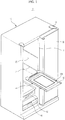
- FIG. 1 is a perspective view illustrating major components of a refrigerator in accordance with an embodiment.
- the refrigerator 1 includes a cabinet 10 defining a storage compartment 20, and a door 30 to open or close the storage compartment 20.
- the door 30 is pivotally rotatable relative to the cabinet 10 to open or close the storage compartment 20.
- a hinge 31 is coupled to at least one of upper and lower ends of the door 30.
- the storage compartment 20 is defined in the cabinet 10 and functions to keep food at a low temperature. There may be a plurality of storage compartments 20 as necessary. The plurality of storage compartments 20 is separated from one another by a partition 11 provided in the cabinet 10.
- a first storage container 50 and a second storage container 60 may be arranged in a lower region of the storage compartment 20 so as to provide separate storage spaces.
- the first and second storage containers 50 and 60 are slidable relative to the storage compartment 20.
- a shelf assembly 40 may be placed in the storage compartment 20 to divide the storage compartment 20 into a plurality of spaces.
- the shelf assembly 40 may be secured to, or be slidable relative to an inner wall of the storage compartment 20.
- Food stored in the storage compartment 20 is cooled by cold air generated from an evaporator (not shown).
- the cold air enables uniform cooling of food within the storage compartment 20. Note that cold air has no ability to cool only specific food rapidly.
- the refrigerator includes an ice thermal storage device 100 provided to come into contact with food.
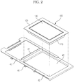
- FIG. 2 is a perspective view illustrating the shelf assembly of the refrigerator in accordance with the embodiment.
- the shelf assembly 40 includes a support frame 41 coupled to the inner wall of the storage compartment 20 and a shelf 42 fitted into the support frame 41.
- the inner wall of the storage compartment 20 is provided with a support structure 21 and the support frame 41 is provided with a mounting structure 44 corresponding to the support structure 21.
- the support structure 21 may be a groove indented in the inner wall of the storage compartment 20 and the mounting structure 44 may be a protrusion corresponding to the groove.
- the support structure 21 may be a protrusion and the mounting structure 44 may be a corresponding groove.
- the shelf 42 may be slidably fitted into the support frame 41. As such, when attempting to take out food placed on the shelf 42, the shelf 42 is pulled out so as to be slidably moved out of the storage compartment 20.
- the support frame 41 is provided with a plurality of stoppers (not shown), realizing stepwise sliding movement of the shelf 42.
- the sliding movement of the shelf 42 out of the storage compartment 20 may cause food placed on the shelf 42 to fall rearward.
- the shelf 42 is provided at a rear end thereof with an anti-fall bar 43 having a predetermined height.
- the ice thermal storage device 100 may be coupled to the shelf 42.
- the shelf 42 may have a seating recess 45 having a shape corresponding to the ice thermal storage device 100 such that the ice thermal storage device 100 is seated in the seating recess 45.
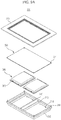
- FIG. 3 is an exploded perspective view illustrating the ice thermal storage device in accordance with the embodiment
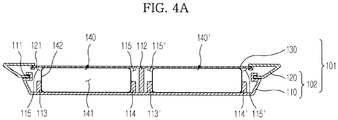
- FIG. 4A is a sectional view of the ice thermal storage device in accordance with the embodiment.
- the ice thermal storage device 100 includes an ice thermal storage pack 140 in which an ice thermal material 141 is sealed, and a case 101 in which the ice thermal storage pack 140 is received.
- the ice thermal storage material 141 may be phase change material (PCM), which is in liquid phase at a room temperature and is changed to a solid phase at a temperature of the storage compartment 20 when the ice thermal storage device 100 is placed in the storage compartment 20 as illustrated in FIG. 1 .
- the ice thermal storage material 141 may increase or decrease in volume while undergoing phase change from liquid to solid, or vice versa.
- the ice thermal storage material 141 may be any one of water, a mixture of water and a PCM, and other aqueous solutions.
- the constituent components of the ice thermal storage material 141 may be determined based on the temperature of the storage compartment 20 illustrated in FIG. 1 .
- the ice thermal storage material 141 is sealed by an enclosure 142 surrounding the ice thermal storage material 141. Since the ice thermal storage material 141 may increase or decrease in volume during phase change, the enclosure 142 is made of an elastic material to cope with the volume change of the ice thermal storage material 141.
- the enclosure 142 is made of a synthetic resin film, such as a polyethylene film.
- the ice thermal storage pack 140 may be fabricated by sandwiching the ice thermal storage material 141 between two synthetic resin films and attaching rims of the synthetic resin films.
- the ice thermal storage pack 140 may be provided with a fixing hole 143.
- the fixing hole 143 may be located at a bonding region of the synthetic resin films and a plurality of fixing holes may be provided as necessary.
- the case 101 includes a housing 102 in which the ice thermal storage pack 140 is received, and a heat transfer plate 130 coupled to the housing 102 so as to come into contact with the ice thermal storage pack 140.
- the housing 102 defines an external appearance of the ice thermal storage device 100.
- the housing 102 may have a top opening in which the heat transfer plate 130 is located.
- the housing 102 may include a first housing 110 defining a bottom surface and a second housing 120 coupled to the first housing 110 to support the heat transfer plate 130 coupled thereto.
- the rim of the first housing 110 may be bent upward to define a sidewall of the case 101.
- An assembly groove 111 is formed in an upper end of the first housing 110, and a lower end of the second housing 120 is configured so as to be fitted into the assembly groove 111, enabling engagement of the first housing 110 and the second housing 120.
- the second housing 120 is provided with rails 121 to which the heat transfer plate 130 is slidably fitted.
- the rails 121 may be attached to an inner ceiling surface of the second housing 120 to extend in a longitudinal direction of the heat transfer plate 130 by a predetermined length. More particularly, two rails 121 may be provided to support opposite sides of the heat transfer plate 130 respectively.
- the heat transfer plate 130 is located above the ice thermal storage pack 140 such that a lower surface of the heat transfer plate 130 comes into contact with the ice thermal storage pack 140.
- the heat transfer plate 130 assists efficient heat-exchange between relative hot food and the relatively cold ice thermal storage pack 140, which increases cooling efficiency of food.
- the heat transfer plate 130 may be made of a metallic material and more particularly, a metal having high thermal conductivity and chemical stability against water.
- the heat transfer plate 130 is made of an aluminum alloy.
- a surface of the heat transfer plate 130 may be cooled to a temperature below zero, which may cause injury to a user hand when the user's hand touches the metallic heat transfer plate 130 when attempting to take out food.
- a coating layer (not shown) may be formed on an upper surface of the heat transfer plate 130 on which food is placed.
- the coating layer may be made of a general material used to coat a metallic surface. For example, fluorine coating or synthetic resin coating may be used.
- the case 101 containing the heat transfer plate 130 receives load of food.
- a load carrying member 112 is provided in the housing 102 to carry the load of the food applied to the heat transfer plate 130.
- the load carrying member 112 is vertically installed such that a lower end thereof is fixed on an inner bottom surface of the housing 102 and an upper end thereof comes into contact with the heat transfer plate 130 to carry it.
- the load carrying member 112 may be formed integrally with the housing 102.
- the load carrying member 112 may extend in a longitudinal direction of the housing 102 to divide the interior space of the housing 102 into two spaces. Ice thermal storage packs 140 and 140' may be arranged respectively in the spaces divided by the load carrying member 112.
- Support bars 113 and 114 may extend in a longitudinal direction of the ice thermal storage pack 140 to support lateral surfaces of the ice thermal storage pack 140.
- the support bars 113 and 114 may be fixed on the inner bottom surface of the housing 102. At least a part of the lateral surface of the ice thermal storage pack 140 does not come into contact with the corresponding support bar 113 or 114, to enable formation of an expansion induction region 115 which will be described hereinafter.
- upper ends of the support bars 113 and 114 are located lower than the upper surface of the ice thermal storage pack 140.
- the support bars 113 and 114 may include a first support bar 113 and a second support bar 114 to support opposite lateral surfaces of the ice thermal storage pack 140.
- the housing 102 may be provided at the inner bottom surface thereof with a fixing pin 118 corresponding to the fixing hole 143. As the fixing pin 118 is fastened into the fixing hole 143, the ice thermal storage pack 140 may be kept at a fixed position. Note that a plurality of fixing pins 118 and a plurality of fixing holes 143 may be provided.
- the expansion induction region 115 is defined between the upper ends of the support bars 113 and 114 and the inner ceiling surface of the case 101.
- the expansion induction region 115 extends in a longitudinal direction of the support bars 113 and 114 along the upper ends of the support bars 113 and 114.
- a portion of the ice thermal storage pack 140 supported by the support bars 113 and 114 is limited in expansion and therefore, the remaining lateral surfaces of the ice thermal storage pack 140 not supported by the support bars 113 and 114 may expand in a longitudinal direction of the heat transfer plate 130 into the expansion induction region 115.
- Allowing expansion of only a part of the ice thermal storage pack 140 into the expansion induction region 115 other than the entire lateral surface of the ice thermal storage pack 140 may assure that the lower surface of the heat transfer plate 130 continuously comes into close contact with the upper surface of the ice thermal storage pack 140. As such, high cooling efficiency may be maintained even if the ice thermal storage pack 140 is deformed due to phase change of the ice thermal storage material 141.
- FIG. 4B is a sectional view of the ice thermal storage device in accordance with another embodiment
- FIG. 4C is a sectional view of the ice thermal device in accordance with another embodiment.
- Variation in the volume of the ice thermal storage material 141 may cause the enclosure of the ice thermal storage material 141 to break due to pressure applied from the ice thermal storage material 141.
- a predetermined quantity of air may be present in the form of bubbles within the ice thermal storage pack 140 along with the ice thermal storage material 141.
- the air tends to be reduced in volume when the volume of the ice thermal storage material 141 increases via phase change to a solid.
- Such a reduction in the volume of the air may offset the increase in the volume of the ice thermal storage material 141 even if the volume of the ice thermal storage pack 140 does not increase.
- the air acts to reduce pressure applied to the enclosure 142 by the ice thermal storage material 141, preventing breakage of the enclosure 142.
- the air has a lower density than the ice thermal storage material 141 and may be located above the ice thermal storage material 141 within the ice thermal storage pack 140. Also, the air has a lower thermal conductivity than the heat transfer plate 130 and may deteriorate heat transfer between the ice thermal storage material 141 and the heat transfer plate 130.
- An air-bubble guide region 116 is provided to guide upward expansion of an upper edge of the ice thermal storage pack 140.
- the air which has a lower density than the ice thermal storage material 141, may be collected in the air-bubble guide region 116.
- the air-bubble guide region 116 may be provided near the expansion induction region 115.
- the air-bubble guide region 116 may be provided between the upper edge of the ice thermal storage pack 140 and the heat transfer plate as illustrated in FIG. 4B , or may be provided between the upper edge of the ice thermal storage pack 140 and the housing 102 as illustrated in FIG. 4C .
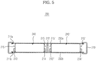
- FIG. 5 is a sectional view of an ice thermal storage device in accordance with another embodiment.
- the ice thermal storage device 200 includes an ice thermal storage pack 240, a first heat transfer plate 230a and a second heat transfer plate 230b arranged to come into contact with upper and lower surfaces of the ice thermal storage pack 240 respectively, and a housing 210 to which the first heat transfer plate 230a and the second heat transfer plate 230b are coupled.
- the housing 210 may be provided with rails 211a and 211b for coupling of the first and second heat transfer plates 230a and 230b.
- the first heat transfer plate 230a and the second heat transfer plate 230b are slidably fitted into the respective rails 211a and 211b.
- the first heat transfer plate 230a and the second heat transfer plate 230b may have the same configuration as the heat transfer plate 130 illustrated in FIGS. 3 and 4A .
- Support bars 213 and 214 and a load carrying member 212 may be secured to the housing 210 to extend between opposite inner wall surfaces of the housing 210.
- the ice thermal storage device 200 may perform heat transfer through upper and lower sides thereof.
- Food located on the first heat transfer plate 230a may be directly cooled by coming into contact with the first heat transfer plate 230a, whereas food located below the second heat transfer plate 230b may be indirectly cooled by cold air which is generated by heat exchange with the second heat transfer plate 230b.
- FIGS. 6A and 6B are views illustrating expansion of the ice thermal storage pack included in the ice thermal storage device in accordance with different embodiments.
- the ice thermal storage material 141 illustrated in FIG. 6A is in liquid phase.
- the ice thermal storage pack 140 is supported at opposite sides thereof by the first support bar 113 and the second support bar 114.
- Air 144 which is present in the ice thermal storage pack 140 along with the ice thermal storage material 141, occupies an upper interior space of the ice thermal storage pack 140.
- the volume of the ice thermal storage material 141 expands if the ice thermal storage material 141 is changed to a solid phase under the influence of the surrounding low temperature.
- the ice thermal storage material 141 illustrated in FIG. 6B is in a solid phase. Expansion of a portion of the ice thermal storage pack 140 in contact with the support bars 113 and 114 is limited, which causes the ice thermal storage pack 140 to be expanded into the expansion induction region 115. In this case, the ice thermal storage pack 140 may maintain constant contact with the heat transfer plate 130. In addition, since the air 144 present in the ice thermal storage pack 140 is likely to be collected into the air-bubble guide region 116 during expansion of the ice thermal storage pack 140, it may be possible to prevent the air 144 from hindering heat transfer between the heat transfer plate 130 and the ice thermal storage material 141.
- FIG. 7 is a perspective view illustrating the ice thermal device in accordance with another embodiment.
- the ice thermal storage device 100 may be mounted in the storage compartment 20.
- the inner wall of the storage compartment 20 is provided with the support structure 21 and the ice thermal storage device 100 is externally provided with a mounting structure 117 corresponding to the support structure 21.
- the support structure 21 may be a groove indented in the inner wall of the storage compartment 20 and the mounting structure 117 may be a protrusion corresponding to the groove.
- the support structure 21 may be a protrusion and the mounting structure 117 may be a corresponding groove.
- the ice thermal storage device 200 illustrated in FIG. 5 may be mounted in the storage compartment 20 in the same manner.
- FIG. 8 is a sectional view illustrating an ice thermal storage device in accordance with another embodiment.
- the first storage container 50 may have a bottom opening 51 and a seating recess 52 around the opening 51.
- the second storage container 60 may have a top opening 61.
- the ice thermal storage device 200 may be provided at an outer periphery thereof with a seating protrusion 217 having a shape corresponding to that of the seating recess 52. As the seating protrusion 217 is fitted into the seating recess 52, the ice thermal storage device 200 is mounted to the first storage container 50.
- Food received in the first storage container 50 above the first heat transfer plate 230a may be cooled by the ice thermal storage pack 240.
- Food received in the second storage container 60 may be indirectly cooled as interior cold air of the second storage container 60 is cooled by a lower surface of the second heat transfer plate 230b.
- FIG. 9A is a perspective view illustrating an ice thermal storage device in accordance with a further embodiment
- FIG. 9B is a sectional view of the ice thermal storage device illustrated in FIG. 9A .
- an ice thermal storage device 300 includes an ice thermal storage pack 340, a heat transfer plate 330 arranged to come into contact with the ice thermal storage pack 340, a first housing 310 in which the ice thermal storage pack 340 is received, and a second housing 320 coupled to the first housing 310.
- the ice thermal storage pack 340 is identical to the ice thermal storage pack 140 illustrated in FIG. 3 .
- the ice thermal storage pack 340 is fixed to the first housing 310 in the same method as that as illustrated in FIG. 3 .
- the first housing 310 is provided at corners thereof with upwardly-protruding fastening pieces 319.
- the heat transfer plate 330 is provided with fastening holes 331 and the second housing 320 is provided with fastening recesses 322.
- the heat transfer plate 330 may be secured to the top of the first housing 310 as the fastening pieces 319 penetrate the fastening holes 331.
- the second housing 320 may be coupled to the first housing 310 as the fastening pieces 319 are inserted into the fastening recesses 322 and simultaneously, may apply pressure to the heat transfer plate 330 so as to secure the heat transfer plate 330.
- the heat transfer plate 330 and the second housing 320 are successively coupled using the fastening pieces 319, which results in easy assembly and simplified manufacture of the ice thermal storage device 300.
- an ice thermal storage pack usable with a refrigerator is configured to maintain constant contact with a heat transfer plate even if the volume of the ice thermal storage pack increases due to phase change of an ice thermal storage material sealed in the ice thermal storage pack.
- the ice thermal storage pack has the effect of continuously maintaining cooling efficiency of food. Further, the ice thermal storage pack is received in a case that protects the ice thermal storage pack from external shock, having no risk of breakage.
- the case prevents leakage of the ice thermal storage pack, which prevents damage to food due to the leakage of the ice thermal storage pack.
Landscapes
- Engineering & Computer Science (AREA)
- Chemical & Material Sciences (AREA)
- Combustion & Propulsion (AREA)
- Physics & Mathematics (AREA)
- Mechanical Engineering (AREA)
- Thermal Sciences (AREA)
- General Engineering & Computer Science (AREA)
- Devices That Are Associated With Refrigeration Equipment (AREA)
Claims (13)
- Réfrigérateur (1) comprenant :une armoire (10);un compartiment de stockage (20) défini dans l'armoire (10); etun dispositif de stockage thermique de la glace (100, 200, 300) placé dans le compartiment de stockage (20), dans lequel le dispositif de stockage thermique de la glace comprend:un boîtier (101) comprenant au moins une plaque de transfert de chaleur (130, 230a, 330); etun bloc de stockage thermique de glace (140, 240, 340) reçu dans le boîtier et disposé pour entrer en contact avec au moins une plaque de transfert de chaleur,dans lequel ledit bloc de stockage thermique de glace (140, 240, 340) comprend une enceinte (142) d'un matériau élastique dans laquelle un matériau de stockage thermique de glace (141) est scellé, dans lequel l'enceinte (101) comprend une zone d'induction d'expansion (115, 115') pour fournir un espace d'expansion pour le bloc de stockage thermique de glace, de manière à maintenir le contact entre le bloc de stockage thermique de glace et la plaque de transfert thermique, etle boîtier (101) comprend une barre de support (113, 113', 114, 114') faisant saillie vers le haut, espacée d'une distance prédéterminée d'une surface intérieure du boîtier et servant à soutenir une surface latérale de la glace (140, 240, 340).
- Réfrigérateur selon la revendication 1, dans lequel une extrémité supérieure de la barre de support (113, 113', 114, 114') est située plus bas qu'une surface supérieure du bloc de stockage thermique de la glace.
- Réfrigérateur selon la revendication 2, dans lequel la zone d'induction d'expansion (115, 115') est définie par un espace entre l'extrémité supérieure de la barre de support (113, 113', 114, 114') et la surface intérieure du boîtier (101), et le bloc de stockage thermique de glace est expansible dans la zone d'induction d'expansion.
- Réfrigérateur selon la revendication 1, dans lequel le boîtier (101) comprend une zone de guidage de bulle d'air (116, 116') pour guider l'air intérieur du bloc de stockage thermique de la glace pendant l'expansion du bloc de stockage thermique de la glace, de manière à maintenir le contact entre le bloc de stockage thermique de la glace et la plaque de transfert de chaleur.
- Réfrigérateur selon la revendication 4, dans lequel la zone de guidage de la bulle d'air (116, 116') est définie par un espace au-dessus d'un bord supérieur de la glace du bloc de stockage thermique (140, 240, 340).
- Réfrigérateur selon la revendication 1, dans lequel :le boîtier (101) comprend un premier logement (110) dans lequel le bloc de stockage thermique de glace est reçu et un second logement (120) auquel la plaque de transfert de chaleur est couplée; etle premier logement (110) et le second logement (120) sont couplés l'un à l'autre de telle sorte que la plaque de transfert de chaleur (130, 330) entre en contact étroit avec la glace.
- Réfrigérateur selon la revendication 1, dans lequel le boîtier (101) comprend en outre un élément porteur de charge (112) pour porter la plaque de transfert de chaleur (130, 230a, 330).
- Réfrigérateur selon la revendication 7, dans lequel:l'élément porteur de charge (112) divise l'intérieur de la caisse (101) en une pluralité d'espaces; etune pluralité de blocs de stockage thermique de glace est disposée respectivement dans la pluralité d'espaces.
- Réfrigérateur selon la revendication 1, dans lequel la plaque de transfert thermique (230a, b) comprend une première plaque de transfert thermique (230a) et une deuxième plaque de transfert thermique (230b) pour entrer en contact avec les surfaces supérieure et inférieure du bloc de stockage thermique de glace (240, 240') respectivement.
- Réfrigérateur selon la revendication 1, comprenant en outre un ensemble d'étagères (40) fixé à une paroi intérieure du compartiment de stockage (20),
dans lequel le dispositif de stockage thermique de la glace (100) est couplé à l'étagère (42) de telle sorte que les aliments sont placés sur le dispositif de stockage thermique de la glace. - Réfrigérateur selon la revendication 10, dans lequel:l'étagère (40) comprend un élément de support (21) fixé à la paroi intérieure du compartiment de stockage (20) et un élément d'étagère (42) monté de manière coulissante dans l'élément de support (24); etl'étagère (42) comporte un évidement (45) dont la forme correspond à celle du dispositif de stockage thermique de la glace (100).
- Réfrigérateur selon la revendication 1, comprenant en outre un guide (21) prévu au niveau de la paroi intérieure du compartiment de stockage (20),
dans lequel le dispositif de stockage thermique de la glace (100) comprend en outre une partie d'accouplement (117) couplée au guide, le dispositif de stockage thermique de la glace servant de tablette sur laquelle les aliments sont placés. - Réfrigérateur selon la revendication 1, comprenant en outre un récipient de stockage (50) reçu dans le compartiment de stockage (20) pour fournir un espace de stockage séparé,
dans lequel le dispositif de stockage thermique de glace (200) est monté sur une surface inférieure du conteneur de stockage (50) et sert à refroidir les aliments reçus dans le conteneur de stockage.
Applications Claiming Priority (1)
| Application Number | Priority Date | Filing Date | Title |
|---|---|---|---|
| KR1020100087207A KR101697113B1 (ko) | 2010-09-06 | 2010-09-06 | 냉장고 |
Publications (3)
| Publication Number | Publication Date |
|---|---|
| EP2426440A2 EP2426440A2 (fr) | 2012-03-07 |
| EP2426440A3 EP2426440A3 (fr) | 2018-01-24 |
| EP2426440B1 true EP2426440B1 (fr) | 2020-07-22 |
Family
ID=44763800
Family Applications (1)
| Application Number | Title | Priority Date | Filing Date |
|---|---|---|---|
| EP11177183.8A Active EP2426440B1 (fr) | 2010-09-06 | 2011-08-11 | Réfrigérateur |
Country Status (4)
| Country | Link |
|---|---|
| US (1) | US8966932B2 (fr) |
| EP (1) | EP2426440B1 (fr) |
| KR (1) | KR101697113B1 (fr) |
| CN (1) | CN102384620B (fr) |
Families Citing this family (18)
| Publication number | Priority date | Publication date | Assignee | Title |
|---|---|---|---|---|
| KR101573592B1 (ko) * | 2012-04-16 | 2015-12-11 | 엘지전자 주식회사 | 냉장고용 냉각 장치 |
| US9175888B2 (en) | 2012-12-03 | 2015-11-03 | Whirlpool Corporation | Low energy refrigerator heat source |
| US9593870B2 (en) | 2012-12-03 | 2017-03-14 | Whirlpool Corporation | Refrigerator with thermoelectric device for ice making |
| KR101586537B1 (ko) * | 2013-11-11 | 2016-01-18 | 동부대우전자 주식회사 | 축냉제가 내장된 선반 및 이를 포함하는 냉장고 |
| CN103727721B (zh) * | 2013-12-06 | 2016-04-13 | 北京工业大学 | 一种用于冰箱冷冻室或冰柜的蓄冷速冻器 |
| WO2015152488A1 (fr) * | 2014-04-02 | 2015-10-08 | 주식회사 성진스크린 | Dispositif de stockage à froid pour réfrigérateur |
| KR101667660B1 (ko) | 2014-04-02 | 2016-10-20 | (주)성진스크린 | 냉장고용 축냉장치 |
| GB2526613A (en) * | 2014-05-30 | 2015-12-02 | Skm Advanced Products Ltd | A tilt board |
| CN104180581B (zh) * | 2014-08-22 | 2016-06-22 | 安徽中家智锐科技有限公司 | 蓄冷保鲜板及包含其的蓄冷系统 |
| KR102336200B1 (ko) * | 2014-12-24 | 2021-12-08 | 삼성전자주식회사 | 냉장고 |
| WO2017076585A1 (fr) * | 2015-11-02 | 2017-05-11 | BSH Hausgeräte GmbH | Appareil frigorifique doté d'un espace de rangement subdivisé |
| CN105588393B (zh) * | 2015-12-30 | 2018-04-20 | 青岛海尔股份有限公司 | 冰箱及其控制方法 |
| US10648724B2 (en) * | 2016-09-06 | 2020-05-12 | Whirlpool Corporation | Cold plate shelf assembly for a refrigerator |
| CN107192195A (zh) * | 2017-05-16 | 2017-09-22 | 合肥华凌股份有限公司 | 一种冰箱 |
| US10823490B2 (en) * | 2017-10-12 | 2020-11-03 | Whirlpool Corporation | Shelf assembly for appliance |
| EP3552703A1 (fr) * | 2018-04-09 | 2019-10-16 | Eppendorf AG | Dispositifs de mise en température de laboratoire |
| CN109163491B (zh) * | 2018-09-27 | 2023-11-14 | 澳柯玛股份有限公司 | 一种恒温保鲜装置 |
| KR20210057397A (ko) * | 2019-11-12 | 2021-05-21 | 삼성전자주식회사 | 냉장고 |
Family Cites Families (36)
| Publication number | Priority date | Publication date | Assignee | Title |
|---|---|---|---|---|
| US68258A (en) * | 1867-08-27 | Anthony b | ||
| US60716A (en) * | 1867-01-01 | Improved peeseryfflg-house | ||
| US3971231A (en) * | 1974-03-27 | 1976-07-27 | Juanita Derry | Refrigerator with dry ice coolant |
| JPS623659Y2 (fr) * | 1981-01-19 | 1987-01-27 | ||
| US4565074A (en) * | 1982-01-18 | 1986-01-21 | Morgan Marshall M | Ice tray for use with a portable ice chest |
| US4748823A (en) * | 1984-12-07 | 1988-06-07 | Nippondenso Co., Ltd. | Automotive refrigerator |
| US4923086A (en) * | 1989-01-18 | 1990-05-08 | The Vollrath Company, Inc. | Ice guards |
| DE4419728A1 (de) * | 1994-06-06 | 1995-12-07 | Krupp Polysius Ag | Zweischichtkühler |
| JPH09108088A (ja) * | 1995-10-20 | 1997-04-28 | Tokuji Yumine | コースタ |
| NO982971A (no) * | 1998-06-26 | 1999-12-27 | H&R Ind Inc | Fremgangsmåte for transport og lagring av varer, samt container egnet for samme |
| US6427475B1 (en) * | 1998-12-17 | 2002-08-06 | Abbott Laboratories | Nested cooler system |
| JP4194155B2 (ja) | 1998-12-18 | 2008-12-10 | 三洋電機株式会社 | 電気冷蔵庫 |
| JP2001201225A (ja) * | 2000-01-20 | 2001-07-27 | Sanden Corp | 保冷ボックス |
| JP2002107078A (ja) | 2000-09-29 | 2002-04-10 | Sanyo Electric Co Ltd | 蓄熱装置及びそれを備えた冷蔵庫 |
| DE20018635U1 (de) * | 2000-10-31 | 2001-03-01 | Dade Behring Marburg GmbH, 35041 Marburg | Isolierbehälter |
| US6415623B1 (en) * | 2001-01-05 | 2002-07-09 | Cold Sell Systems, Llc | Point of sale product chiller |
| CA2406250C (fr) * | 2001-10-18 | 2008-12-02 | Raymonde Crete | Contenant alimentaire a section de refroidissement amovible |
| US7260438B2 (en) * | 2001-11-20 | 2007-08-21 | Touchsensor Technologies, Llc | Intelligent shelving system |
| US6691530B2 (en) | 2002-05-13 | 2004-02-17 | Lg Electronics Inc. | Rapid cooling apparatus |
| US20040031273A1 (en) * | 2002-08-16 | 2004-02-19 | Mario Lanctot | Freezing Container Sealed by Ice |
| DE20318471U1 (de) * | 2003-11-26 | 2004-03-11 | Rotho Kunststoff Ag | Behälter aus Kunststoff |
| JP2005192533A (ja) | 2004-01-09 | 2005-07-21 | Technican:Kk | 液面接触による食品の急速冷凍方法及び装置 |
| US7310967B2 (en) * | 2004-02-20 | 2007-12-25 | Aragon Daniel M | Temperature controlled container |
| US7444830B2 (en) * | 2004-03-08 | 2008-11-04 | The Boeing Company | Aircraft galley carts and other insulated food storage units, and methods for their use |
| ITMI20060410U1 (it) * | 2006-11-22 | 2008-05-23 | Whirlpool Co | Ripiano per frigorifero con funzione refrigerante e frigorifero con tale piano |
| US8056359B2 (en) * | 2007-07-09 | 2011-11-15 | Electrolux Home Products, Inc. | Fast freeze shelf |
| US8726689B2 (en) * | 2008-05-06 | 2014-05-20 | Samsung Electronics Co., Ltd. | Refrigerator with cold storage unit |
| KR101161129B1 (ko) * | 2008-05-06 | 2012-06-28 | 삼성전자 주식회사 | 냉장고 |
| JP4367574B2 (ja) * | 2008-10-17 | 2009-11-18 | パナソニック株式会社 | 冷蔵庫 |
| CN201555416U (zh) * | 2009-04-28 | 2010-08-18 | 上海中日家用电器有限公司 | 冰箱用具有蓄冷功能的抽屉 |
| GB2459392B (en) * | 2009-05-29 | 2010-04-07 | Softbox Systems Ltd | Transport container |
| US8474274B2 (en) * | 2010-05-11 | 2013-07-02 | The Boeing Company | Refrigerated container |
| KR20110139844A (ko) * | 2010-06-24 | 2011-12-30 | 삼성전자주식회사 | 센서장치를 갖는 냉장고용 수납용기 및 이를 갖는 냉장고 |
| KR20120023272A (ko) * | 2010-09-01 | 2012-03-13 | 삼성전자주식회사 | 직냉식 냉장고 및 그 제어방법 |
| US20130255306A1 (en) * | 2012-03-27 | 2013-10-03 | William T. Mayer | Passive thermally regulated shipping container employing phase change material panels containing dual immiscible phase change materials |
| US9366467B2 (en) * | 2012-06-20 | 2016-06-14 | Igloo Products Corp. | Iceless chill chamber cooler |
-
2010
- 2010-09-06 KR KR1020100087207A patent/KR101697113B1/ko active IP Right Grant
-
2011
- 2011-08-04 US US13/137,307 patent/US8966932B2/en not_active Expired - Fee Related
- 2011-08-11 EP EP11177183.8A patent/EP2426440B1/fr active Active
- 2011-08-30 CN CN201110259925.4A patent/CN102384620B/zh not_active Expired - Fee Related
Non-Patent Citations (1)
| Title |
|---|
| ANONYMOUS: "Matière plastique - Wikipédia", 5 July 2019 (2019-07-05), XP055602714, Retrieved from the Internet <URL:https://fr.wikipedia.org/wiki/Matière_plastique> [retrieved on 20190705] * |
Also Published As
| Publication number | Publication date |
|---|---|
| KR20120025072A (ko) | 2012-03-15 |
| US20120055191A1 (en) | 2012-03-08 |
| KR101697113B1 (ko) | 2017-01-18 |
| CN102384620A (zh) | 2012-03-21 |
| CN102384620B (zh) | 2015-10-07 |
| EP2426440A2 (fr) | 2012-03-07 |
| US8966932B2 (en) | 2015-03-03 |
| EP2426440A3 (fr) | 2018-01-24 |
Similar Documents
| Publication | Publication Date | Title |
|---|---|---|
| EP2426440B1 (fr) | Réfrigérateur | |
| EP2787308B1 (fr) | Réfrigérateur | |
| EP2587199B1 (fr) | Réfrigérateur | |
| US9624022B2 (en) | Storage container utilizing two different heat insulating materials in combination with a temperature control unit and a heat storage material placed within the container | |
| US20160161174A1 (en) | Refrigerator | |
| EP2808628B1 (fr) | Bac à légumes pour réfrigérateurs et réfrigérateur comprenant celui-ci | |
| KR101705641B1 (ko) | 냉장고 및 냉장고의 제빙 장치의 조립 방법 | |
| US7677681B2 (en) | Kimchi refrigerator | |
| US20180031298A1 (en) | Refrigerator | |
| US20150130335A1 (en) | Shelf including a cold storage material therein, and refrigerator having the same | |
| JP5761936B2 (ja) | 冷凍冷蔵庫 | |
| CN103673451B (zh) | 制冷器具 | |
| CN103673473B (zh) | 具有横梁的制冷器具 | |
| JP2020008254A (ja) | 冷蔵庫 | |
| EP3757484A1 (fr) | Appareil réfrigérateur | |
| EP2643647B1 (fr) | Réfrigérateur | |
| JP7209147B2 (ja) | 冷蔵庫 | |
| JP2012017968A (ja) | 冷蔵庫 | |
| JP3749087B2 (ja) | 冷蔵庫 | |
| JP2020008259A (ja) | 冷蔵庫 | |
| EP2588820B1 (fr) | Réfrigérateur | |
| JP2020008258A (ja) | 冷蔵庫 | |
| JPWO2018167867A1 (ja) | 冷蔵庫 | |
| EP4293304A1 (fr) | Réfrigérateur | |
| JP2002081827A (ja) | 冷蔵庫 |
Legal Events
| Date | Code | Title | Description |
|---|---|---|---|
| AK | Designated contracting states |
Kind code of ref document: A2 Designated state(s): AL AT BE BG CH CY CZ DE DK EE ES FI FR GB GR HR HU IE IS IT LI LT LU LV MC MK MT NL NO PL PT RO RS SE SI SK SM TR |
|
| AX | Request for extension of the european patent |
Extension state: BA ME |
|
| PUAI | Public reference made under article 153(3) epc to a published international application that has entered the european phase |
Free format text: ORIGINAL CODE: 0009012 |
|
| RAP1 | Party data changed (applicant data changed or rights of an application transferred) |
Owner name: SAMSUNG ELECTRONICS CO., LTD. |
|
| PUAL | Search report despatched |
Free format text: ORIGINAL CODE: 0009013 |
|
| AK | Designated contracting states |
Kind code of ref document: A3 Designated state(s): AL AT BE BG CH CY CZ DE DK EE ES FI FR GB GR HR HU IE IS IT LI LT LU LV MC MK MT NL NO PL PT RO RS SE SI SK SM TR |
|
| AX | Request for extension of the european patent |
Extension state: BA ME |
|
| RIC1 | Information provided on ipc code assigned before grant |
Ipc: F25D 11/00 20060101AFI20171220BHEP Ipc: F25D 25/02 20060101ALI20171220BHEP |
|
| STAA | Information on the status of an ep patent application or granted ep patent |
Free format text: STATUS: REQUEST FOR EXAMINATION WAS MADE |
|
| 17P | Request for examination filed |
Effective date: 20180517 |
|
| RBV | Designated contracting states (corrected) |
Designated state(s): AL AT BE BG CH CY CZ DE DK EE ES FI FR GB GR HR HU IE IS IT LI LT LU LV MC MK MT NL NO PL PT RO RS SE SI SK SM TR |
|
| STAA | Information on the status of an ep patent application or granted ep patent |
Free format text: STATUS: EXAMINATION IS IN PROGRESS |
|
| 17Q | First examination report despatched |
Effective date: 20190711 |
|
| GRAP | Despatch of communication of intention to grant a patent |
Free format text: ORIGINAL CODE: EPIDOSNIGR1 |
|
| STAA | Information on the status of an ep patent application or granted ep patent |
Free format text: STATUS: GRANT OF PATENT IS INTENDED |
|
| INTG | Intention to grant announced |
Effective date: 20200224 |
|
| GRAS | Grant fee paid |
Free format text: ORIGINAL CODE: EPIDOSNIGR3 |
|
| GRAA | (expected) grant |
Free format text: ORIGINAL CODE: 0009210 |
|
| STAA | Information on the status of an ep patent application or granted ep patent |
Free format text: STATUS: THE PATENT HAS BEEN GRANTED |
|
| AK | Designated contracting states |
Kind code of ref document: B1 Designated state(s): AL AT BE BG CH CY CZ DE DK EE ES FI FR GB GR HR HU IE IS IT LI LT LU LV MC MK MT NL NO PL PT RO RS SE SI SK SM TR |
|
| REG | Reference to a national code |
Ref country code: GB Ref legal event code: FG4D |
|
| REG | Reference to a national code |
Ref country code: CH Ref legal event code: EP |
|
| REG | Reference to a national code |
Ref country code: DE Ref legal event code: R096 Ref document number: 602011067865 Country of ref document: DE |
|
| REG | Reference to a national code |
Ref country code: AT Ref legal event code: REF Ref document number: 1293780 Country of ref document: AT Kind code of ref document: T Effective date: 20200815 |
|
| REG | Reference to a national code |
Ref country code: IE Ref legal event code: FG4D |
|
| REG | Reference to a national code |
Ref country code: LT Ref legal event code: MG4D |
|
| REG | Reference to a national code |
Ref country code: AT Ref legal event code: MK05 Ref document number: 1293780 Country of ref document: AT Kind code of ref document: T Effective date: 20200722 |
|
| PG25 | Lapsed in a contracting state [announced via postgrant information from national office to epo] |
Ref country code: AT Free format text: LAPSE BECAUSE OF FAILURE TO SUBMIT A TRANSLATION OF THE DESCRIPTION OR TO PAY THE FEE WITHIN THE PRESCRIBED TIME-LIMIT Effective date: 20200722 Ref country code: SE Free format text: LAPSE BECAUSE OF FAILURE TO SUBMIT A TRANSLATION OF THE DESCRIPTION OR TO PAY THE FEE WITHIN THE PRESCRIBED TIME-LIMIT Effective date: 20200722 Ref country code: GR Free format text: LAPSE BECAUSE OF FAILURE TO SUBMIT A TRANSLATION OF THE DESCRIPTION OR TO PAY THE FEE WITHIN THE PRESCRIBED TIME-LIMIT Effective date: 20201023 Ref country code: NO Free format text: LAPSE BECAUSE OF FAILURE TO SUBMIT A TRANSLATION OF THE DESCRIPTION OR TO PAY THE FEE WITHIN THE PRESCRIBED TIME-LIMIT Effective date: 20201022 Ref country code: FI Free format text: LAPSE BECAUSE OF FAILURE TO SUBMIT A TRANSLATION OF THE DESCRIPTION OR TO PAY THE FEE WITHIN THE PRESCRIBED TIME-LIMIT Effective date: 20200722 Ref country code: HR Free format text: LAPSE BECAUSE OF FAILURE TO SUBMIT A TRANSLATION OF THE DESCRIPTION OR TO PAY THE FEE WITHIN THE PRESCRIBED TIME-LIMIT Effective date: 20200722 Ref country code: BG Free format text: LAPSE BECAUSE OF FAILURE TO SUBMIT A TRANSLATION OF THE DESCRIPTION OR TO PAY THE FEE WITHIN THE PRESCRIBED TIME-LIMIT Effective date: 20201022 Ref country code: PT Free format text: LAPSE BECAUSE OF FAILURE TO SUBMIT A TRANSLATION OF THE DESCRIPTION OR TO PAY THE FEE WITHIN THE PRESCRIBED TIME-LIMIT Effective date: 20201123 Ref country code: LT Free format text: LAPSE BECAUSE OF FAILURE TO SUBMIT A TRANSLATION OF THE DESCRIPTION OR TO PAY THE FEE WITHIN THE PRESCRIBED TIME-LIMIT Effective date: 20200722 Ref country code: ES Free format text: LAPSE BECAUSE OF FAILURE TO SUBMIT A TRANSLATION OF THE DESCRIPTION OR TO PAY THE FEE WITHIN THE PRESCRIBED TIME-LIMIT Effective date: 20200722 |
|
| PGFP | Annual fee paid to national office [announced via postgrant information from national office to epo] |
Ref country code: DE Payment date: 20201026 Year of fee payment: 10 |
|
| PG25 | Lapsed in a contracting state [announced via postgrant information from national office to epo] |
Ref country code: LV Free format text: LAPSE BECAUSE OF FAILURE TO SUBMIT A TRANSLATION OF THE DESCRIPTION OR TO PAY THE FEE WITHIN THE PRESCRIBED TIME-LIMIT Effective date: 20200722 Ref country code: PL Free format text: LAPSE BECAUSE OF FAILURE TO SUBMIT A TRANSLATION OF THE DESCRIPTION OR TO PAY THE FEE WITHIN THE PRESCRIBED TIME-LIMIT Effective date: 20200722 Ref country code: RS Free format text: LAPSE BECAUSE OF FAILURE TO SUBMIT A TRANSLATION OF THE DESCRIPTION OR TO PAY THE FEE WITHIN THE PRESCRIBED TIME-LIMIT Effective date: 20200722 Ref country code: IS Free format text: LAPSE BECAUSE OF FAILURE TO SUBMIT A TRANSLATION OF THE DESCRIPTION OR TO PAY THE FEE WITHIN THE PRESCRIBED TIME-LIMIT Effective date: 20201122 |
|
| PG25 | Lapsed in a contracting state [announced via postgrant information from national office to epo] |
Ref country code: NL Free format text: LAPSE BECAUSE OF FAILURE TO SUBMIT A TRANSLATION OF THE DESCRIPTION OR TO PAY THE FEE WITHIN THE PRESCRIBED TIME-LIMIT Effective date: 20200722 |
|
| REG | Reference to a national code |
Ref country code: CH Ref legal event code: PL |
|
| REG | Reference to a national code |
Ref country code: DE Ref legal event code: R097 Ref document number: 602011067865 Country of ref document: DE |
|
| PG25 | Lapsed in a contracting state [announced via postgrant information from national office to epo] |
Ref country code: IT Free format text: LAPSE BECAUSE OF FAILURE TO SUBMIT A TRANSLATION OF THE DESCRIPTION OR TO PAY THE FEE WITHIN THE PRESCRIBED TIME-LIMIT Effective date: 20200722 Ref country code: LI Free format text: LAPSE BECAUSE OF NON-PAYMENT OF DUE FEES Effective date: 20200831 Ref country code: CZ Free format text: LAPSE BECAUSE OF FAILURE TO SUBMIT A TRANSLATION OF THE DESCRIPTION OR TO PAY THE FEE WITHIN THE PRESCRIBED TIME-LIMIT Effective date: 20200722 Ref country code: CH Free format text: LAPSE BECAUSE OF NON-PAYMENT OF DUE FEES Effective date: 20200831 Ref country code: DK Free format text: LAPSE BECAUSE OF FAILURE TO SUBMIT A TRANSLATION OF THE DESCRIPTION OR TO PAY THE FEE WITHIN THE PRESCRIBED TIME-LIMIT Effective date: 20200722 Ref country code: EE Free format text: LAPSE BECAUSE OF FAILURE TO SUBMIT A TRANSLATION OF THE DESCRIPTION OR TO PAY THE FEE WITHIN THE PRESCRIBED TIME-LIMIT Effective date: 20200722 Ref country code: MC Free format text: LAPSE BECAUSE OF FAILURE TO SUBMIT A TRANSLATION OF THE DESCRIPTION OR TO PAY THE FEE WITHIN THE PRESCRIBED TIME-LIMIT Effective date: 20200722 Ref country code: LU Free format text: LAPSE BECAUSE OF NON-PAYMENT OF DUE FEES Effective date: 20200811 Ref country code: RO Free format text: LAPSE BECAUSE OF FAILURE TO SUBMIT A TRANSLATION OF THE DESCRIPTION OR TO PAY THE FEE WITHIN THE PRESCRIBED TIME-LIMIT Effective date: 20200722 Ref country code: SM Free format text: LAPSE BECAUSE OF FAILURE TO SUBMIT A TRANSLATION OF THE DESCRIPTION OR TO PAY THE FEE WITHIN THE PRESCRIBED TIME-LIMIT Effective date: 20200722 |
|
| REG | Reference to a national code |
Ref country code: BE Ref legal event code: MM Effective date: 20200831 |
|
| PLBE | No opposition filed within time limit |
Free format text: ORIGINAL CODE: 0009261 |
|
| STAA | Information on the status of an ep patent application or granted ep patent |
Free format text: STATUS: NO OPPOSITION FILED WITHIN TIME LIMIT |
|
| PG25 | Lapsed in a contracting state [announced via postgrant information from national office to epo] |
Ref country code: AL Free format text: LAPSE BECAUSE OF FAILURE TO SUBMIT A TRANSLATION OF THE DESCRIPTION OR TO PAY THE FEE WITHIN THE PRESCRIBED TIME-LIMIT Effective date: 20200722 |
|
| GBPC | Gb: european patent ceased through non-payment of renewal fee |
Effective date: 20201022 |
|
| 26N | No opposition filed |
Effective date: 20210423 |
|
| PG25 | Lapsed in a contracting state [announced via postgrant information from national office to epo] |
Ref country code: SK Free format text: LAPSE BECAUSE OF FAILURE TO SUBMIT A TRANSLATION OF THE DESCRIPTION OR TO PAY THE FEE WITHIN THE PRESCRIBED TIME-LIMIT Effective date: 20200722 |
|
| PG25 | Lapsed in a contracting state [announced via postgrant information from national office to epo] |
Ref country code: FR Free format text: LAPSE BECAUSE OF NON-PAYMENT OF DUE FEES Effective date: 20200922 |
|
| PG25 | Lapsed in a contracting state [announced via postgrant information from national office to epo] |
Ref country code: BE Free format text: LAPSE BECAUSE OF NON-PAYMENT OF DUE FEES Effective date: 20200831 Ref country code: SI Free format text: LAPSE BECAUSE OF FAILURE TO SUBMIT A TRANSLATION OF THE DESCRIPTION OR TO PAY THE FEE WITHIN THE PRESCRIBED TIME-LIMIT Effective date: 20200722 Ref country code: IE Free format text: LAPSE BECAUSE OF NON-PAYMENT OF DUE FEES Effective date: 20200811 Ref country code: GB Free format text: LAPSE BECAUSE OF NON-PAYMENT OF DUE FEES Effective date: 20201022 |
|
| REG | Reference to a national code |
Ref country code: NL Ref legal event code: MP Effective date: 20200722 |
|
| REG | Reference to a national code |
Ref country code: DE Ref legal event code: R119 Ref document number: 602011067865 Country of ref document: DE |
|
| PG25 | Lapsed in a contracting state [announced via postgrant information from national office to epo] |
Ref country code: TR Free format text: LAPSE BECAUSE OF FAILURE TO SUBMIT A TRANSLATION OF THE DESCRIPTION OR TO PAY THE FEE WITHIN THE PRESCRIBED TIME-LIMIT Effective date: 20200722 Ref country code: MT Free format text: LAPSE BECAUSE OF FAILURE TO SUBMIT A TRANSLATION OF THE DESCRIPTION OR TO PAY THE FEE WITHIN THE PRESCRIBED TIME-LIMIT Effective date: 20200722 Ref country code: CY Free format text: LAPSE BECAUSE OF FAILURE TO SUBMIT A TRANSLATION OF THE DESCRIPTION OR TO PAY THE FEE WITHIN THE PRESCRIBED TIME-LIMIT Effective date: 20200722 |
|
| PG25 | Lapsed in a contracting state [announced via postgrant information from national office to epo] |
Ref country code: MK Free format text: LAPSE BECAUSE OF FAILURE TO SUBMIT A TRANSLATION OF THE DESCRIPTION OR TO PAY THE FEE WITHIN THE PRESCRIBED TIME-LIMIT Effective date: 20200722 |
|
| PG25 | Lapsed in a contracting state [announced via postgrant information from national office to epo] |
Ref country code: DE Free format text: LAPSE BECAUSE OF NON-PAYMENT OF DUE FEES Effective date: 20220301 |