EP3552703A1 - Dispositifs de mise en température de laboratoire - Google Patents
Dispositifs de mise en température de laboratoire Download PDFInfo
- Publication number
- EP3552703A1 EP3552703A1 EP18166337.8A EP18166337A EP3552703A1 EP 3552703 A1 EP3552703 A1 EP 3552703A1 EP 18166337 A EP18166337 A EP 18166337A EP 3552703 A1 EP3552703 A1 EP 3552703A1
- Authority
- EP
- European Patent Office
- Prior art keywords
- chamber
- housing
- front wall
- laboratory
- spacer
- Prior art date
- Legal status (The legal status is an assumption and is not a legal conclusion. Google has not performed a legal analysis and makes no representation as to the accuracy of the status listed.)
- Withdrawn
Links
Images


Classifications
-
- C—CHEMISTRY; METALLURGY
- C12—BIOCHEMISTRY; BEER; SPIRITS; WINE; VINEGAR; MICROBIOLOGY; ENZYMOLOGY; MUTATION OR GENETIC ENGINEERING
- C12M—APPARATUS FOR ENZYMOLOGY OR MICROBIOLOGY; APPARATUS FOR CULTURING MICROORGANISMS FOR PRODUCING BIOMASS, FOR GROWING CELLS OR FOR OBTAINING FERMENTATION OR METABOLIC PRODUCTS, i.e. BIOREACTORS OR FERMENTERS
- C12M41/00—Means for regulation, monitoring, measurement or control, e.g. flow regulation
- C12M41/12—Means for regulation, monitoring, measurement or control, e.g. flow regulation of temperature
- C12M41/14—Incubators; Climatic chambers
-
- B—PERFORMING OPERATIONS; TRANSPORTING
- B01—PHYSICAL OR CHEMICAL PROCESSES OR APPARATUS IN GENERAL
- B01L—CHEMICAL OR PHYSICAL LABORATORY APPARATUS FOR GENERAL USE
- B01L7/00—Heating or cooling apparatus; Heat insulating devices
-
- B—PERFORMING OPERATIONS; TRANSPORTING
- B01—PHYSICAL OR CHEMICAL PROCESSES OR APPARATUS IN GENERAL
- B01L—CHEMICAL OR PHYSICAL LABORATORY APPARATUS FOR GENERAL USE
- B01L2200/00—Solutions for specific problems relating to chemical or physical laboratory apparatus
- B01L2200/06—Fluid handling related problems
- B01L2200/0689—Sealing
-
- B—PERFORMING OPERATIONS; TRANSPORTING
- B01—PHYSICAL OR CHEMICAL PROCESSES OR APPARATUS IN GENERAL
- B01L—CHEMICAL OR PHYSICAL LABORATORY APPARATUS FOR GENERAL USE
- B01L2200/00—Solutions for specific problems relating to chemical or physical laboratory apparatus
- B01L2200/14—Process control and prevention of errors
- B01L2200/143—Quality control, feedback systems
- B01L2200/147—Employing temperature sensors
-
- B—PERFORMING OPERATIONS; TRANSPORTING
- B01—PHYSICAL OR CHEMICAL PROCESSES OR APPARATUS IN GENERAL
- B01L—CHEMICAL OR PHYSICAL LABORATORY APPARATUS FOR GENERAL USE
- B01L2300/00—Additional constructional details
- B01L2300/02—Identification, exchange or storage of information
- B01L2300/025—Displaying results or values with integrated means
- B01L2300/027—Digital display, e.g. LCD, LED
-
- B—PERFORMING OPERATIONS; TRANSPORTING
- B01—PHYSICAL OR CHEMICAL PROCESSES OR APPARATUS IN GENERAL
- B01L—CHEMICAL OR PHYSICAL LABORATORY APPARATUS FOR GENERAL USE
- B01L2300/00—Additional constructional details
- B01L2300/06—Auxiliary integrated devices, integrated components
- B01L2300/0627—Sensor or part of a sensor is integrated
- B01L2300/0663—Whole sensors
Definitions
- the invention relates to a laboratory tempering device for storing laboratory samples at a target temperature. It particularly relates to an incubator for the growth of cell cultures.
- Laboratory tempering devices are needed to store laboratory samples in a shielded environment at a specified target temperature.
- Incubators are used in biological and medical laboratories to maintain cells in cell culture under controlled environmental conditions, thus enabling the growth of living cells in vitro .
- the temperature and the gas composition or the atmospheric humidity in the interior of an incubator chamber isolated from the environment are kept at the desired values by the apparatus of the incubator.
- Eukaryotic cells must be cultured in CO 2 incubators.
- the atmosphere is formed by air with a certain CO 2 - and O 2 content and a certain humidity, a suitable temperature is often 37 ° C, these parameters are usually adjustable.
- a homogeneous temperature distribution or a homogeneous climate in the incubator chamber and a resistance to interference from external influences is desirable.
- Such laboratory tempering devices have a chamber for receiving the laboratory samples to be tempered, this chamber is usually disposed within a housing and at least partially separated by insulating material of this. Access to the chamber, in which the user stores and removes the samples inside the housing, in particular in the chamber, generally takes place via a chamber opening or housing opening, which can be closed by means of a housing door.
- a problem of laboratory temperature control devices of the prior art is that thermal bridges form at the junctions between the housing and the chamber, which may lie in particular in the region of the chamber opening or housing opening, which may lead to undesired disturbances of the chamber climate.
- Incubators were observed to be attached to the Chamber interior walls near the thermal bridges condensate forms, since at these points heat is drawn off locally via the outgoing thermal bridges, resulting in a local cooling of the inner walls near the joints and condensation.
- the formation of condensate should be avoided, as it contaminates the interior and germs serves as a basis for growth.
- the thermal bridges lead to a continuous loss of energy. In principle, however, a low energy consumption of the laboratory temperature control devices should be sought. Similar properties, ie a homogeneous temperature distribution, a noise insensitivity and a low energy consumption are also desired in laboratory temperature control devices designed as refrigerators.
- the present invention is therefore based on the object to provide an improved laboratory tempering, the chamber interior is efficiently thermally decoupled from the environment.
- the laboratory temperature control device according to the invention which is in particular an incubator for cell cultures, serves for the temperature-controlled storage of laboratory samples and comprises: a housing with a housing interior surrounded by at least one housing wall, a temperature-controlled chamber arranged in the housing with a chamber interior surrounded by at least one chamber wall for receiving the Laboratory samples, a plurality of spacer elements, wherein a spacer element has at least one first connecting portion, by means of which the spacer element and the housing are connected and at least one second connection portion spaced from the second connecting portion, by means of which the spacer element and the chamber are connected, so that the chamber by means of Spacers spaced from the housing wherein the spacer elements are each formed using a material having a thermal conductivity of less than 15 W / (mK).
- thermal insulators Due to the low thermal conductivity of the spacer elements, these act as thermal insulators.
- the heat flow between the chamber and housing is thereby significantly reduced compared to the conventional solutions in which the chamber and housing are connected by metallic, so excellent conductive connection means.
- the formation of thermal bridges between the chamber and housing is thus reduced to a minimum. Since the chamber is held by spacers on the housing, on the one hand can be dispensed with further connecting elements or surface connecting portions between the chamber and housing, which would each form undesirable thermal bridge.
- the mechanical position stability of the chamber in the housing is ensured by the spacer elements whose material and in particular their shape and number can be optimized or optimized for this task.
- the provision of a plurality of spacers allows the reduction of the heat-conducting cross-section of the connection of the chamber and the housing and on the other hand provides the possibility of optimally distributing the mechanical load between the chamber and the housing. Furthermore, it is possible by the choice of at least one spacer element, which is adapted for the floating mounting of the spacer element on the chamber and / or on the housing, to allow relative movements between the chamber and the housing so as to prevent thermally induced mechanical stresses.
- a spacer element is formed using a non-metallic material.
- non-metallic materials have a significantly lower thermal conductivity than metals.
- the thermal conductivity of the material, in particular of the non-metallic material is preferably less than 10 W / (mK), preferably less than 5 W / (mK), particularly preferably less than 2.5 W / (mK).
- a spacer element is formed using a material comprising plastic, and consists in particular of plastic.
- the plastic can be reinforced with fibers or fillers.
- the spacer may consist of a composite material.
- Plastic-based materials have a significantly lower thermal conductivity than metals.
- the thermal conductivity of the material, in particular of the plastic-containing material is preferably less than 2 W / (mK), preferably less than 1 W / (mK), particularly preferably less than 0.8 W / (mK).
- the material is a high-performance plastic, which is in particular resistant to high temperatures and in particular tolerates operating temperatures of 180 ° C to 200 ° C. Such temperatures are used in incubators during sterilization cycles to sterilize the chamber interior.
- high-performance plastics also withstand very low temperatures which are present in laboratory tempering devices designed as refrigerators and freezers.
- the materials polyphenylene sulfide (abbreviation PPS), polyether ether ketone (PEEK), polyether ketone (PEK) and filled polybutylene terephthalate (PBT) have proven particularly suitable. Their mechanical properties can be further improved, in particular by adding fibers and fillers.
- the thermal conductivity of solids is basically a temperature-dependent parameter.
- the specification of the thermal conductivity refers to a standard measurement at 20 ° C.
- Thermal conductivities of thermally insulating materials can be determined in particular using the industry standard DIN 52612-1.
- the spacer consists mainly of the material with the thermal conductivity less than 15 W / (mK).
- the spacer element is completely, or substantially completely, made of the material having the thermal conductivity less than 15 W / (mK).
- the spacer at least partially between the first connecting portion and the second connecting portion, in particular in a third portion of the material with the thermal conductivity is less than 15 W / (mK). This ensures that the heat flow in the spacer element is completely or essentially completely over a section, in particular the third section, which has a thermal conductivity of less than 15 W / (mK).
- the thermal decoupling between the first and the second connecting portion is not only dependent on the material property "thermal conductivity", but also on the geometric nature of the spacer.
- thermal conductivity material property
- the spacer element-given size and shape has at least one recess and / or at least one cavity. Such a cavity or such a recess allow to provide a spacer element, on the one hand a low heat flow between generates the first and the second connecting portion and on the other hand has a sufficient mechanical strength.
- a first connecting portion is considered as such a region of the spacer element, which is arranged in the connecting position, in which the chamber and the housing are connected by the spacer element, on the housing and this in particular contacted.
- the first connecting portion is mounted on the housing, in particular slidably mounted.
- a second connecting portion is considered as such a portion of the spacer, which is arranged in the connecting position to the chamber and this particular contacted.
- the second connecting portion is mounted on the chamber, and may also be slidably mounted.
- a spacer element has at least one cavity and / or at least one recess.
- the spacer element has at least one section, which is referred to in particular as the third section, which connects the first and the second connecting section.
- This at least a third portion is preferably web-shaped, whereby the heat flow is reduced and the thermal resistance is large. Along the longitudinal direction of the bridge this is mechanically strong on train or thrust.
- the web-shaped portion between the first and second connecting portion is linearly aligned, in particular along a virtual axis connecting the first and second connecting portion.
- a plurality of third sections are provided which connect a first and a second connecting section.
- the first and / or the second connecting portion of the spacer member at least one hole, by means of which the spacer element is connectable to the housing or the chamber.
- at least one hole formed as a slot can be provided, which can be set up for the sliding mounting of a connecting element which is connected to the housing or the chamber.
- a metal pin, in particular a screw provided, which extends through the hole or slot and connects the first and the second connecting portion with the housing or the chamber.
- the spacer element preferably has more than one first and / or second connecting section. As a result, the mechanical forces of the chamber attachment can be distributed even cheaper.
- the spacer element has a plate-shaped section or is plate-shaped.
- a plate-shaped spacer element is particularly well mechanically loadable in directions parallel to the main plane of the plate and has in such directions due to the small cross section on an increased thermal resistance, which is desired for thermal decoupling.
- a plate-shaped component can advantageously be mounted on a parallel surface, in particular on a chamber wall or housing wall, which then stabilizes the position of the plate-shaped component.
- the spacer element has a plurality of, in particular interconnected web portions, which are in particular aligned at least partially in the direction of a connecting portion at which the chamber is connected to the spacer element.
- the spacer element has one or more recesses, openings or cavities and / or is at least partially porous.
- the laboratory tempering device has at least one spacer element, which is connected to a front wall of the housing and a front wall of the chamber.
- the laboratory tempering device has a plurality of spacer elements, which are connected in the lower region of the chamber to the housing, in particular a front wall of the housing, and the chamber, in particular a front wall of the chamber.
- the lower region is in particular a bottom-side front wall of the chamber, which by means of the spacer elements with a bottom-side front wall of the housing is connected.
- “Bottom side” means “near the bottom wall", the bottom wall is a bottom outer wall of the chamber or housing.
- the laboratory tempering device has a plurality of spacer elements, which are connected in the upper region of the chamber with the housing, in particular a front wall of the housing, and the chamber, in particular a front wall of the chamber.
- the upper area is in particular a ceiling-side front wall of the chamber, which is connected by means of the spacer elements with a ceiling-side front wall of the housing.
- "Ceiling side" means “near the ceiling wall”
- the ceiling wall is an upper outer wall of the chamber or housing.
- At least one spacer element is provided, which is designed for the floating mounting of the spacer element on the chamber and / or on the housing.
- the floating bearing allows a relative movement between the chamber and housing, which is used to prevent thermally induced, mechanical stresses in the laboratory tempering.
- the floating mounting succeeds in particular via a sliding bearing of the corresponding first and / or second connecting portion of the spacer element.
- the slide bearing succeeds in particular by the corresponding connecting portion having a slot in which slides a sliding member of the chamber or the housing and at the same time causes the connection.
- Such a laboratory tempering device offers the advantage that the gap formed between the chamber door and the housing door when the external door is closed is not in contact with the housing. This is due to the fact that the second seal in the closed state of the outer door by the gap-free contact first seal laterally bounds the gap. Any contact of the contained in the space, heated by the chamber air mixture with the non-tempered outer wall of the housing and thus any convection-induced heat transfer between the gap and the housing is therefore impossible.
- the first seal and the second seal are preferably made of an elastomeric material which is resistant to high temperatures, in particular up to 200 ° C.
- the elastomeric material is in particular an elastomeric plastic, in particular a silicone plastic, in particular a plastic foam, preferably a silicone foam.
- the first seal connects the housing front wall and the chamber front wall.
- the first seal has a minimum or average material thickness, which, measured perpendicular to the housing front wall, is less than this shortest connection or the gap width between the housing front wall and the chamber front wall.
- the minimum or average material thickness d2 of the first seal is less than 1 cm, in particular 0.8 cm, preferably between 0.2 cm and 1 cm.
- the shortest connection is given in particular by the gap width between the housing front wall and the chamber front wall.
- the gap width d1 is preferably more than 1.0 cm, and is preferably in the range of more than 1.2 cm, preferably in the range 1.0 cm to 2.0 cm, preferably between 1.2 cm and 1.8 cm, preferably between 1 , 2 and 1.6 cm.
- the gap can also be wider, so the first seal can be wider. Due to the mentioned preferred embodiments (maximum heat flow path in the direction of the gap width and minimum heat-conducting cross-section perpendicular to this direction), the thermal resistance of the first seal is maximal.
- the second seal preferably has a circumferential first sealing area closer to the outer door and having a higher modulus of elasticity than a second second sealing area preferably integrally connected to the first sealing area, which in particular is softer and closer to the outer door in the closed position the first seal is located and contacted.
- a softer sealing area between the outer door and the housing makes it easier to seal the gap between the outer door and the chamber door, and also reduces the forces required to close the chamber door, making operation easier for the user.
- the first sealing region is preferably made using an elastomer, in particular silicone, the second sealing region preferably using a foamed elastomer, in particular silicone foam.
- the wall end portion of the housing front wall and the wall end portion of the chamber front wall are arranged without overlapping with respect to a projection direction perpendicular to the plane of the chamber opening, that is, the projections of the wall end portions on this plane do not intersect each other.
- the particular planar wall end portion of the housing front wall and the particular planar wall end portion of the chamber front wall are preferably in the same plane.
- the laboratory tempering device for storing laboratory samples is in particular a temperature control cabinet for tempering laboratory samples. Such devices are electrically operated and have a voltage connection.
- the temperature control cabinet tempers the laboratory samples, meaning that it keeps the inside of the housing and thus the laboratory samples stored there within tolerances Temperature control on a user-adjustable target temperature in particular. This may be above room temperature (ambient temperature), as is the case with a warming cabinet or incubator, or may be below room temperature, as is the case with a refrigerator or freezer.
- a climatic parameter prevailing in the interior of the housing is preferably also regulated within the framework of tolerances.
- This climate parameter may be the atmospheric humidity, and / or a gas concentration, eg a CO2, O2 and / or N2 concentration.
- a climate cabinet is, for example, an incubator for laboratory samples consisting of living cell cultures.
- the laboratory temperature control device preferably has a housing.
- the housing is preferably an outer housing whose housing walls are in contact with the environment.
- the housing door can accordingly be an outer housing door which, in the closed position, adjoins the surroundings.
- the housing door has in particular a hinge device, which connects the housing door pivotally connected to the housing.
- a hinge device which connects the housing door pivotally connected to the housing.
- Such a swing gate is moved by rotation between an open position and the closed position.
- the hinge device can lie, in particular, on the outer edge of a parallelepiped-shaped housing that is oriented vertically in the intended use of the laboratory cabinet device and that adjoins the housing opening.
- the bottom plate of a cuboid housing is arranged horizontally in the intended use of the laboratory cabinet device, the side walls of the housing are arranged in particular vertically, and the cover plate of the housing is in particular the bottom plate arranged horizontally opposite.
- the chamber door or housing door may also be a sliding door, which is moved by a translational movement between an open position and the closing position.
- a mixed pivoting / translational movement of the chamber door or housing door is possible.
- a data processing device is preferably part of the electrical control device that controls functions of the laboratory temperature control device.
- the functions of the control device are implemented in particular by electronic circuits.
- the control device may comprise a processing unit (CPU) for processing data and / or a microprocessor, which may include the data processing device.
- the control device and / or the data processing device is preferably designed for carrying out a control method, which is also referred to as control software or control program.
- the functions of the incubator and / or the control device can be described in method steps. They can be implemented as components of the control program, in particular as subroutines of the control program.
- the laboratory temperature control device is preferably a laboratory temperature control cabinet, in particular an incubator.
- the incubator is a laboratory incubator and thus a device that can create and maintain controlled climatic conditions for various biological development and growth processes. In particular, it serves to create and maintain a microclimate with controlled gas and / or humidity and / or temperature conditions in the incubator chamber, which treatment may be time dependent.
- the laboratory incubator in particular a treatment device of the laboratory incubator, may in particular comprise a timer, in particular a timer, a tempering device designed as a heating and / or cooling device and preferably a setting for controlling a replacement gas supplied to the incubator, an adjusting device for the Composition of the gas in the incubator of the incubator, in particular for adjusting the CO 2 and / or the O 2 and / or the N 2 content content of the gas and / or an adjusting device for adjusting the humidity in the incubator of the incubator.
- a timer in particular a timer
- a tempering device designed as a heating and / or cooling device and preferably a setting for controlling a replacement gas supplied to the incubator
- an adjusting device for the Composition of the gas in the incubator of the incubator in particular for adjusting the CO 2 and / or the O 2 and / or the N 2 content content of the gas and / or an adjusting device for adjusting the humidity in the incubator of the incubator.
- a control device with at least one control loop, to which at least one tempering device is assigned as actuator and at least one temperature sensor as measuring element.
- Humidity can be controlled, although the humidity itself is not measured by a humidity sensor (rH sensor) and the humidity is not the input variable of the control loop.
- a well filled with water in the incubator chamber can be heated or cooled to adjust the humidity via the evaporation.
- CO 2 incubators are used in particular for the cultivation of animal or human cells.
- Incubators may have turning devices for turning the at least one cell culture container and / or a shaking device for shaking or moving the at least one cell culture container.
- the control device can be set up such that a program parameter or a control parameter of the incubator is selected automatically as a function of other data.
- a treatment of the at least one cell culture in at least one cell culture container controlled by a control parameter corresponds in particular to a climate treatment which is subjected to the at least one cell culture.
- Possible parameters, in particular program parameters, in particular user parameters, which are used for influencing a climatic treatment in particular define the temperature of the incubator room in which the at least one sample is incubated, the relative gas concentration of O 2 - and / or CO 2 and / or N 2 in the incubation interior, the humidity in the incubation interior and / or at least one flow parameter that influences or defines the sequence, in particular the sequence, of an incubation treatment program consisting of several steps.
- the tempering device may be a combined heating / cooling device. It is preferably only a heating device. In particular, this can generate the heat via an electrical resistance wire.
- the laboratory tempering device or the incubator can have exactly one chamber, but can also have a plurality of chambers whose atmosphere (temperature, relative gas concentration, atmospheric humidity) can be adjustable in particular individually or in a collective manner.
- a typical size of the interior of a chamber is between 50 and 400 liters, although for special applications (IVF) smaller chamber sizes are possible, in particular 10 to 49 liters.
- the features mentioned in the invention and preferred embodiments of the laboratory temperature control device according to the invention can also be used to design a laboratory temperature control device according to the invention according to the second or third particular aspect.
- the laboratory temperature control device according to claim 1 can also be configured by features of the laboratory temperature control device according to the invention according to the second or third particular aspect. Further preferred embodiments of the laboratory temperature control device according to the invention can be taken from the description of the embodiments according to the figures.
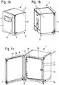
- Fig. 1a shows the designed as an incubator 1 laboratory tempering 1 for the growth of cell cultures, here designed as a CO2 incubator laboratory demoerator for the growth of eukaryotic cells.
- the incubator 1 has a housing 2 with a housing interior surrounded by at least one housing wall 2 and a temperature-controlled chamber 3 arranged in the housing (see Fig. 2a ) with a chamber interior surrounded by at least one chamber wall for receiving the laboratory samples.
- the outer walls of the housing are connected so that they carry all other components of the incubator.
- the housing rests on pedestals 8.
- the upper outer side 2d and the non-visible bottom side of the housing and the bottom wall and ceiling wall of the chamber are arranged correspondingly horizontally.
- the direction “downwards” always means the direction of the gravitation, on the basis of which a laboratory temperature control device operated in accordance with the intended purpose is aligned, the direction “upwards” being the opposite direction.
- the direction “forward” refers to the horizontal direction to the front of the closed housing door, the direction “backwards” refers to the horizontal direction to the back of the incubator.
- the chamber is made of stainless steel, the housing of painted metal sheet.
- the housing door 4 carries a user interface device 5, here comprising a touch-sensitive display used by the user to read and input information.
- the housing door has two hinges 9 which connect the housing door to the housing 2.
- a magnetic locking device 7 which includes an upper and lower housing-side holding portion 7a and a top and bottom housing door-side holding portion 7b, the housing door is held in the closed position.
- the housing door has a door handle 6 which is connected to the housing door at the positions of the upper and lower housing door-side holding portions 7b and which extends vertically.
- the housing front wall 2a extends vertically and is aligned with the vertically extending chamber front wall 3a, ie the forward facing surfaces, and here also the rearwardly facing surfaces, the housing front wall 2a and the chamber front wall 3a are substantially in the same plane, see Fig. 7 ,
- Fig. 1c As in Fig. 1c is shown, between the housing front wall 2a and the chamber front wall 3a an elastic seal 12 is introduced, which is held there by means of grooves form-fitting, in which engage the edges of the housing front wall 2a and the chamber front wall 3a, see also Fig. 7 ,
- Fig. 1c the housing door 4 is shown open.
- the chamber door 10 is fastened by means of the hinges 15 to the chamber front wall 3a, and is kept closed in the position shown by a magnetic hand lock 13, so that the chamber interior is not accessible. Due to the transparency of the chamber door 10, the interior is visible to the user in this position.
- the chamber door is held by a circumferential elastic seal 11 of the chamber door gas-tight on the chamber front wall.
- the inner side 4a of the housing door has a circumferential elastic seal 14, which rests flush in the closed state of the housing door on the housing front wall and the peripheral seal 12 there and achieves a gas-tight shielding of the area between the chamber door 10 and the housing door 4a.
- the incubator on two tempering, which temper the chamber interior 3, ie set their temperature by a temperature control.
- a part of the necessary components 18 are arranged between the housing bottom wall 2e and the chamber bottom wall 3e.
- the heating coil of an upper heating circuit (not shown) are thermally coupled and connected to the outside of the chamber ceiling wall 3d and an upper portion of the chamber side walls, here about the upper 2/3 along the height of the side walls 3c of the chamber.
- the heating coils of a lower heating circuit (not shown) are thermally coupled and connected to the outside of the chamber bottom wall 3e and a lower portion of the chamber side walls, here about the bottom 1/3 along the height of the side walls 3c of the chamber.
- a thermal insulation device 19 is provided between the chamber and the housing. It isolates the chamber, with adjoining tempering of the housing, which communicates directly with the outside on its outside.
- the incubator normally operates at outdoor temperatures between 18 ° C and 28 ° C.
- the tempering or temperature control works very efficiently in this area.
- the insulating device comprises a U-shaped bent insulating element 19b made of glass wool or mineral wool, which surrounds the chamber ceiling plate and the two chamber side walls 3c.
- insulating panels 19c made of PIR foam (polyisocyanurate foam), and is closed to the front of the housing and chamber by a circulating Nadelvliesst Shape 19a, which rests against the inside of the housing front wall 2a, the chamber front wall 3a and the seal 12.
- the thermal insulation of the chamber to the outside is optimized by the measures according to the invention.
- a double housing rear wall 16 is attached to the cover rear-mounted components.
- the rear wall is removable by means of a handle 17.
- the incubator has on its rear side two access ports 20, 20 'which allow the user to route cables through openings 20h, 20'h in the back wall of the chamber into the interior of the chamber, for example measuring devices located inside head for.
- a port 20, 20 ' also serves as a spacer which keeps the chamber 3 at a distance from the housing 2 and supports part of the weight of the chamber and its attachments and contents.
- the outwardly facing end 21 of the cylindrical member 20 serves as a first connecting portion, by means of which the spacer element 20 is secured to the housing.
- a third threaded ring 20b and a second threaded ring 20b are screwed onto the cylindrical component 20, so that the housing rear wall 2b is fixed between the second and third threaded ring.
- the cylindrical member 20 corresponding external thread.
- the spacer 20 is constructed analogously. If the access port is not needed, it is filled with a plug 25 of thermally insulating material, eg silicone foam.
- the chamber 3 is held by a plurality of spacer elements at a distance from the housing, which have a thermal conductivity of less than 15 W / (mK), here approx. 0.5 W / (mK) by using a PPS reinforced with fiber fillers.
- the incubator has a plurality of spacer elements 30, 30 ', 30 ", 40, 40', 20, 20 ', wherein a spacer element has at least one first connecting portion 31, 41, 21, by means of which the spacer element and the housing 2 are connected and at least one from the first connecting portion spaced second connecting portion 32, 42, 22, by means of which the spacer element and the chamber are connected.
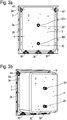
- Fig. 3a shows a rear perspective view of the housing front wall 2a and the chamber 3, arranged between the housing front wall 2a and the chamber front wall 3a spacers 30, 30 ', 30 ", 40, 40' and arranged on the chamber rear wall 3b, also serving as spacers access port 20, 20 'of the incubator of Fig. 1a ,
- the chamber front wall 3a which is aligned with the housing front wall 2a, held at a distance d, which is constant about 14 mm, resulting in one around the chamber opening Circumferential gap 29 which is filled by the thermally insulating seal 12.
- the spacer elements 30, 30 ', 30 ", 40, 40' according to the invention are formed so that they on the one hand the main part of the weight of the chamber, and their attachments and their maximum allowable Fill weight over the entire life of the incubator can easily and reliably wear.
- the number of front-side spacers results from the intersection of the requirements for the mechanical, chemical and thermal load capacity of the compound and the thermal insulation.
- a high-performance plastic was chosen here, in particular a composite with a matrix of high-performance plastic. This was chosen in the present case as PPS GF 40, ie a PPS with 40% addition of glass fibers, here with a further addition of 25% of mineral fillers was provided. This results in an excellent thermal load capacity of up to 220 ° C. This makes it easy to heat the chamber to 180 ° C for sterilization purposes, which is a standard requirement for modern incubators.
- the thermal conductivity of the PPS material is only 0.5 W / (mK), resulting in a high thermal resistance, ideal for the thermal decoupling of chamber and housing.
- the tensile strength of the PPS material according to ISO 527 is about 150 MPa.
- the geometric structure of the front spacers has been optimized with regard to the load to be absorbed and to reduce the heat flow.
- the cross-section determining the heat flow was minimized by the "third section" located between the first and second connecting section of the spacer 30, and on the other hand, the distance to be managed by the heat flow was achieved by maximizing the length of the third section.
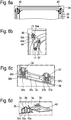
- the bottom-side spacer elements 30, 30 ', 30 "were constructed in such a way that they each have a plurality of web-shaped sections 35a, 35b, 35c, 35d, 35e, which connect the first connecting section 31 to the second connecting section 32.
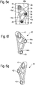
- a front-side spacer element 30, 30 ', 30 ", 40, 40' in the present case is a substantially plate-shaped component which has two opposite main sides, namely those in FIG Fig. 5h or in Fig. 6f visible back of the spacer and the in Fig. 5i or in Fig. 6g visible front of the spacer, which extend parallel to the main plane of the plate-shaped member.
- the views in Fig. 5g and 6e are parallel to this main level.
- the cross section of the front plate-shaped spacer elements parallel to the main plane essentially follows a triangular contour, in the case of the bottom-side spacer elements according to an isosceles triangle, resulting in a favorable distribution of forces.
- the chamber loads the bottom-side spacer elements 30, 30 ', 30 "with a Pressure load, the ceiling-side spacers are loaded by tensile load, the chamber is suspended here on the upper side of the housing front wall.
- the first connecting portion 31 of the bottom spacer 30 is here a bar-shaped area 31, see Fig. 5i which contacts the housing front wall 2a in the assembled state and is mounted by fastening means 51, 52, 51 ', 52' against the housing front wall 2a.
- the first connecting portion 31 has two spaced-apart and connected by the web-shaped connecting portion 35 f sections with the cylindrical holes 34 a and 34 b, the cylinder axes extending perpendicular to the main plane of the plate-shaped spacer 30.
- the holes 34a and 34b are used to mount the central spacer 30, as in FIG Fig. 5b to 5d is shown.
- a spacer element 30, 30 ', 30 is formed by a plate-shaped component approximately in the shape of an isosceles triangle
- the outer web-shaped sections 35a, 35e each subtend an acute angle with the web-shaped section 35f arranged horizontally and at the bottom of the triangle 41 °, in the meeting point of the web-shaped sections 35a, 35e with the web-shaped section 35f, adjacent to each other, are each the oval-cylindrical section with slot 33a, 33b and the cylindrical section
- the outer web-shaped portions 35a, 35e each start from the oval-cylindrical portion and open at the apex of the isosceles triangle at an obtuse angle, the tip being represented there by the first connecting portion 31 consisting of two adjacent cylindrical ones Sections each with a zy Linderförmigen hole 37a, 37b is formed.
- Two further web-shaped sections 35b, 35d form an angle of approximately 57 ° with the web-shaped section 35f.
- the web-shaped portion 35c extends vertically upward perpendicularly to the web-shaped portion 35f and terminates in the apex of the triangle by forking in a Y-shape, and each sub-fork opens into one of the cylindrical portions of the tip.
- the spacer element 30 has by this strut construction a high mechanical stability, in particular against the Pressure load from above, a low weight, and a high thermal resistance to the heat flow, which results from the first connecting portion 31 through the struts 35a, 35b, 35c, 35d, 35e to the second connecting portion 32.
- Said struts have a relatively large length and a transversely to the heat flow seen small cross section, which minimizes the heat flow.
- the spacer 30 has on its front side a recess 36 which is formed to receive another component, here for partially receiving the seal 12 which is arranged in the gap 29.
- the recess further reduces the cross-section mentioned in the paragraph above and increases the thermal resistance.
- the web-shaped struts 35a, 35b, 35c, 35d, 35e running in the region of the recess 36 are each also understood to be a third section of the spacer element which connects in each case a first and second connecting section.
- Fig. 5d shows a perspective cross-sectional view of the housing-side first connecting portion 31 of the centrally disposed spacer element of Fig. 5b , wherein the cross section perpendicular to the main plane of the plate-shaped spacer element and along the line L1 of Fig. 5b runs.
- Two male threaded pins 51a are welded to the back of the housing front wall 2a so as to extend into a hole 34a, 34b of the spacer, respectively.
- a washer 51b and the nut 51 screwed onto the metal pin 51a are used at each hole 34a, 34b to press the first connecting portion 31 against the housing front wall 2a to make the connection.
- the second connecting portion 32 of the bottom spacer 30, 30 ', 30 is formed by a narrower bar-shaped portion 32, see Fig. 5i , which contacts the chamber front wall 3a in the assembled state and is mounted by fastening means 53, 54 against the chamber front wall 2a.
- the second connecting portion 32 has two cylindrical holes 37a, 37b, see Fig. 5h whose cylinder axes extend perpendicular to the main plane of the plate-shaped spacer 30.
- the Holes 37a and 37b are used to mount the spacers 30, 30 ', 30 "on the chamber front wall 3a, as in FIG Fig. 5c is shown.
- a precisely fitting cylindrical metal sleeve 53b is mounted, whose length corresponds to the height of the spacer in this direction.
- a nut head 53, 54 is screwed by means of thread 53c with the metal pin 53a and presses against metal sleeve and spacer 30, which is therefore relieved by the metal sleeve.
- Fig. 5e shows as a part of the Fig. 5a the distance element 30 'shown there on the left in the picture.
- the spacers 40, 40 'at the top of the chamber each have such a sliding attachment by means of slot.
- By fastening by means of the slots a "floating attachment" of the chamber is achieved on the housing.
- This type of storage makes it possible to compensate for thermally induced changes in length of the housing or to reduce the caused by the thermally induced changes in length mechanical stresses. Only the bottom-centrally arranged spacer 30 is not slidably mounted and guarantees the positioning of the chamber even in the presence of thermally induced changes in length.
- Fig. 5f shows a perspective cross-sectional view of the housing-side first connecting portion of the decentralized laterally spaced spacer 30 'of Fig. 5e , wherein the cross section perpendicular to the main plane of the plate-shaped spacer element and along the line L3 of Fig. 5e runs.
- Two metal pins 51'a are respectively welded to the housing front wall 2a and protrude through the slot 33a, 33b.
- a cylindrical sliding sleeve 51'b, 52'b surrounds the metal pin 51'a, 52'a and terminates in a disk-shaped sleeve head, which is pressurized by the nut 51 ', 52', which presses on the thread of the metal pin 51'a , 52'a is screwed on.
- Fig. 6b shows as a part of the Fig. 6a it has a first connecting portion 41, which, as in Fig. 6f and Fig. 6g is recognizable as oval-cylindrical portion 41 is formed, through which the slot 43 a extends.
- This portion 41 is mounted in the mounted position against the housing front wall 2a.
- the nut 55 is screwed to the metal pin 56a and presses the metal sleeve against the housing front wall 2a so that a sliding movement of the spacer 40 between the housing front wall 2a and the metal sleeve 55b is made possible.
- FIG. 12 shows a perspective cross-sectional view of the chamber-side second connecting portions 42, 43 of the spacer 40 of FIG Fig. 6b , wherein the cross-section perpendicular to the main plane of the plate-shaped spacer element and along the line L4 of Fig. 6b runs.
- the sections 42, 43 designated as "second connecting sections" connect the spacer element 40 to the chamber front wall 3a.
- the connecting portions 42 and 43 are cylindrical portions of the spacer 40, as in FIG Fig. 6f, 6g can be seen, through each of which extends a cylindrical hole 44a, 44b. These are used to attach the spacer 40 to the chamber front wall 3a. This has for this purpose two welded with her metal pins 56a, 57a.
- Each of these pins extends into a hole 44a, 44b of the spacer 40.
- a metal sleeve 56b, 57b is fitted, which engages the hole respectively.
- a nut 56, 57 each extending into the hole which rests on the metal sleeve and which is connected to the external thread 56c, 57c of the metal pin 56a, 57a, each of the connecting portions 42, 43 between metal sleeve 56b, 57b and the Chamber front wall 3a stored and fixed so that the pressure force is absorbed by the metal sleeve and the spacer is relieved.
- Fig. 6e shows a plan view of the spacer of the Fig. 6b in which the web-shaped sections 45a, 45b, 45c, 45d between the connecting sections 41, 42, 43 are designated.
- the ridge 45a connects the connecting portion 41 with the connecting portion 43
- the ridge 45b connects the connecting portion 41 with the connecting portion 42
- the ridge 45c connects the connecting portion 42 with the connecting portion 43
- the ridge 45d connects the connecting portion 42 with the strut 45a.
- the web is 45c -anders than the web 35f of the spacer 30 ( Fig. 5f ) not in contact with the corresponding front panel: in Fig. 6c the web is separated by a gap from the chamber front wall 3a.
- the sections 42 and 43 of the spacer are each stored separately on the chamber front wall and therefore, unlike the bar-shaped area 31 in FIG Fig. 5f , considered as two different connecting sections.
- Fig. 7 shows a fragmentary side cross-sectional view of the in Fig. 1a shown incubator, wherein the cross section is parallel to a side wall of the incubator and shows an upper front of the incubator.
- the chamber 3 has a chamber door 10, which is also closed here.
- the housing front wall 2a and the chamber front wall 3a are separated from each other by the first seal 12 which revolves around the chamber opening.
- the first seal is made of silicone foam.
- the outer door 4 has an inner side 4a with a second seal 14, which in the closed state of Outer door on the first seal 12 abuts and rotates around the chamber opening 3z and the housing opening 2z.
- Such a laboratory tempering device offers the advantage that the intermediate space 60 formed between the chamber door and the housing door when the external door is closed is not in contact with the housing. This is due to the fact that the second seal in the closed state of the outer door by the gap-free contact first seal laterally bounds the gap. Any contact of the contained in the space 60, heated by the chamber air mixture with the non-tempered outer wall of the housing and thus any convection-induced heat transfer between the gap 60 and the housing is thus impossible.
- the first seal closes the gap 29 between the housing front wall 2a and the chamber front wall 3a.
- the width of the first seal 12 in the direction d1 is slightly more than 14 mm, since the planar plate ends of the housing front wall 2a and the chamber front wall 3a respectively engage from opposite sides in a corresponding groove of the first seal, resulting in a positive connection between the first seal and the housing front wall 2a and the chamber front wall 3a results.
- the second seal has a peripheral first sealing area 14a closer to the outer door and having a higher modulus of elasticity than the second second sealing area 14b integrally connected to the first sealing area, which is particularly softer and closer to the outer door in the closed position the first seal is located and contacted. Due to the softer sealing area 14b between the outer door 4 and housing 2, the gap between the outer door and chamber door can better seal, also be to close the Chamber door required forces reduced, so that the operation is easier for the user.
- the first sealing area is made using silicone
- the second sealing area 14b is made using a silicone foam.
- the outer door has a heated inner wall 4a. This is, without directly touching the outer wall 4b of the outer door, held by a plurality of spacers 4c on the outer wall 4b of the outer door.
- a spacer element 4c is preferably formed of a material with a thermal conductivity of less than 15 W (mK), in particular of a high-performance plastic, in particular PPS. This further improves the thermal decoupling of the chamber from the environment.
- the wall end portion 2a 'of the housing front wall revolving around the chamber front wall 2a forms the housing opening 2z
- the chamber front wall 3a forms a flange around the chamber opening 3z, which ends in a wall end section 3a' revolving around the chamber opening.
- the wall end portion 2a 'of the housing front wall and the wall end portion 3a' of the chamber front wall each have a thickness of about 2.0 mm and face each other to form the gap 29.
- the already already thin wall end portions are connected together.
- the wall end portion 2a 'of the housing front wall and the wall end portion 3a' of the chamber front wall are here also in the same plane.
- the heat input of the wall end portion 3a 'of the chamber front wall in the seal is low because of the small wall thickness, so that the heat transfer is further reduced.
- the heat transfer between wall end portion 2a 'of the housing front wall and the wall end portion 3a' of the chamber front wall is minimized by means of thermal radiation and further improves the thermal decoupling between the chamber and the housing.
Landscapes
- Chemical & Material Sciences (AREA)
- Health & Medical Sciences (AREA)
- Engineering & Computer Science (AREA)
- Organic Chemistry (AREA)
- Zoology (AREA)
- Wood Science & Technology (AREA)
- Bioinformatics & Cheminformatics (AREA)
- Life Sciences & Earth Sciences (AREA)
- Thermal Sciences (AREA)
- Chemical Kinetics & Catalysis (AREA)
- Biomedical Technology (AREA)
- Biotechnology (AREA)
- Microbiology (AREA)
- Sustainable Development (AREA)
- Physics & Mathematics (AREA)
- Analytical Chemistry (AREA)
- Biochemistry (AREA)
- General Engineering & Computer Science (AREA)
- General Health & Medical Sciences (AREA)
- Genetics & Genomics (AREA)
- Clinical Laboratory Science (AREA)
- Apparatus Associated With Microorganisms And Enzymes (AREA)
- Devices For Use In Laboratory Experiments (AREA)
Priority Applications (6)
| Application Number | Priority Date | Filing Date | Title |
|---|---|---|---|
| EP18166337.8A EP3552703A1 (fr) | 2018-04-09 | 2018-04-09 | Dispositifs de mise en température de laboratoire |
| JP2020554835A JP7299917B2 (ja) | 2018-04-09 | 2019-04-09 | 実験室温度調節装置 |
| PCT/EP2019/058985 WO2019197418A1 (fr) | 2018-04-09 | 2019-04-09 | Dispositifs de thermorégulation de laboratoire |
| US17/046,230 US20210170415A1 (en) | 2018-04-09 | 2019-04-09 | Laboratory temperature control devices |
| EP19715493.3A EP3774041A1 (fr) | 2018-04-09 | 2019-04-09 | Dispositifs de thermorégulation de laboratoire |
| CN201980022611.7A CN111971122B (zh) | 2018-04-09 | 2019-04-09 | 实验室调温装置 |
Applications Claiming Priority (1)
| Application Number | Priority Date | Filing Date | Title |
|---|---|---|---|
| EP18166337.8A EP3552703A1 (fr) | 2018-04-09 | 2018-04-09 | Dispositifs de mise en température de laboratoire |
Publications (1)
| Publication Number | Publication Date |
|---|---|
| EP3552703A1 true EP3552703A1 (fr) | 2019-10-16 |
Family
ID=61913101
Family Applications (2)
| Application Number | Title | Priority Date | Filing Date |
|---|---|---|---|
| EP18166337.8A Withdrawn EP3552703A1 (fr) | 2018-04-09 | 2018-04-09 | Dispositifs de mise en température de laboratoire |
| EP19715493.3A Pending EP3774041A1 (fr) | 2018-04-09 | 2019-04-09 | Dispositifs de thermorégulation de laboratoire |
Family Applications After (1)
| Application Number | Title | Priority Date | Filing Date |
|---|---|---|---|
| EP19715493.3A Pending EP3774041A1 (fr) | 2018-04-09 | 2019-04-09 | Dispositifs de thermorégulation de laboratoire |
Country Status (5)
| Country | Link |
|---|---|
| US (1) | US20210170415A1 (fr) |
| EP (2) | EP3552703A1 (fr) |
| JP (1) | JP7299917B2 (fr) |
| CN (1) | CN111971122B (fr) |
| WO (1) | WO2019197418A1 (fr) |
Families Citing this family (2)
| Publication number | Priority date | Publication date | Assignee | Title |
|---|---|---|---|---|
| CN112858371B (zh) * | 2021-02-02 | 2022-06-03 | 桂林理工大学 | 一种用于室内的建筑热环境实验箱 |
| WO2024020005A1 (fr) * | 2022-07-19 | 2024-01-25 | Becton, Dickinson And Company | Porte-conteneurs en forme de tambour pour flacons d'hémoculture et procédés de mesure et de fonctionnement |
Citations (5)
| Publication number | Priority date | Publication date | Assignee | Title |
|---|---|---|---|---|
| FR705807A (fr) * | 1930-02-20 | 1931-06-12 | Procédé de fermentation et d'entreposage de liquide en fermentation, et appareillage pour la mise en oeuvre de ce procédé | |
| US2233394A (en) * | 1939-10-26 | 1941-03-04 | Westinghouse Electric & Mfg Co | Refrigeration apparatus |
| DE2259377A1 (de) * | 1972-12-04 | 1974-06-27 | Heraeus Gmbh W C | Waermeschrank |
| EP0154536A2 (fr) * | 1984-03-02 | 1985-09-11 | Mallinckrodt, Inc. (a Delaware corporation) | Enceinte à atmosphère contrôlée |
| DE102014212356B3 (de) * | 2014-06-26 | 2015-08-27 | Memmert GmbH + Co. KG | Einbaurahmen für einen Brutschrank |
Family Cites Families (7)
| Publication number | Priority date | Publication date | Assignee | Title |
|---|---|---|---|---|
| US4701415A (en) * | 1984-03-02 | 1987-10-20 | Mallinckrodt, Inc. | Controlled atmosphere enclosure |
| JPH05227942A (ja) * | 1992-02-25 | 1993-09-07 | Unie Data:Kk | 培養装置 |
| US7157270B2 (en) * | 2002-04-24 | 2007-01-02 | Genx International Inc. | Lightweight chamber having variable configurations and a method for making such |
| JP4248512B2 (ja) * | 2005-03-31 | 2009-04-02 | 三洋電機株式会社 | 保管装置 |
| JP4799221B2 (ja) * | 2006-03-06 | 2011-10-26 | 三洋電機株式会社 | アイソレータ用インキュベータ |
| KR101697113B1 (ko) * | 2010-09-06 | 2017-01-18 | 삼성전자주식회사 | 냉장고 |
| JP5727187B2 (ja) * | 2010-09-30 | 2015-06-03 | パナソニックヘルスケアホールディングス株式会社 | インキュベータ |
-
2018
- 2018-04-09 EP EP18166337.8A patent/EP3552703A1/fr not_active Withdrawn
-
2019
- 2019-04-09 CN CN201980022611.7A patent/CN111971122B/zh active Active
- 2019-04-09 JP JP2020554835A patent/JP7299917B2/ja active Active
- 2019-04-09 WO PCT/EP2019/058985 patent/WO2019197418A1/fr unknown
- 2019-04-09 EP EP19715493.3A patent/EP3774041A1/fr active Pending
- 2019-04-09 US US17/046,230 patent/US20210170415A1/en active Pending
Patent Citations (5)
| Publication number | Priority date | Publication date | Assignee | Title |
|---|---|---|---|---|
| FR705807A (fr) * | 1930-02-20 | 1931-06-12 | Procédé de fermentation et d'entreposage de liquide en fermentation, et appareillage pour la mise en oeuvre de ce procédé | |
| US2233394A (en) * | 1939-10-26 | 1941-03-04 | Westinghouse Electric & Mfg Co | Refrigeration apparatus |
| DE2259377A1 (de) * | 1972-12-04 | 1974-06-27 | Heraeus Gmbh W C | Waermeschrank |
| EP0154536A2 (fr) * | 1984-03-02 | 1985-09-11 | Mallinckrodt, Inc. (a Delaware corporation) | Enceinte à atmosphère contrôlée |
| DE102014212356B3 (de) * | 2014-06-26 | 2015-08-27 | Memmert GmbH + Co. KG | Einbaurahmen für einen Brutschrank |
Also Published As
| Publication number | Publication date |
|---|---|
| CN111971122B (zh) | 2023-05-16 |
| JP2021520216A (ja) | 2021-08-19 |
| CN111971122A (zh) | 2020-11-20 |
| JP7299917B2 (ja) | 2023-06-28 |
| EP3774041A1 (fr) | 2021-02-17 |
| US20210170415A1 (en) | 2021-06-10 |
| WO2019197418A1 (fr) | 2019-10-17 |
Similar Documents
| Publication | Publication Date | Title |
|---|---|---|
| DE102014106877B4 (de) | Modulares Inkubatorsystem | |
| EP1957907B1 (fr) | Appareil frigorifique a barre d'isolation pour l'isolation thermique des parois laterales | |
| EP3774041A1 (fr) | Dispositifs de thermorégulation de laboratoire | |
| DE102005021590A1 (de) | Kältegerät mit Rahmenheizung | |
| EP1882142A1 (fr) | Appareil frigorifique a cadre frontal en matiere plastique | |
| DE202016008965U1 (de) | Kühlschrank | |
| DE102008054590A1 (de) | Kältegerät mit einer Eis- und/oder Flüssigkeitsausgabevorrichtung | |
| EP2059748B1 (fr) | Appareil frigorifique intégré comportant un dispositif de distribution | |
| DE102005021592A1 (de) | Kältegerät mit Türöffnungshilfe | |
| WO2006120099A1 (fr) | Corps d'appareil de refrigeration dote d'un canal d'air | |
| EP0658733A1 (fr) | Elément de paroi | |
| EP3764842A1 (fr) | Ensemble armoire de laboratoire, destiné au stockage d'échantillons de laboratoire, à fermeture magnétique | |
| EP2354729B1 (fr) | Dispositif de réglage de températures très basses | |
| EP1957908A1 (fr) | Carcasse pour un appareil frigorifique | |
| EP3764843B1 (fr) | Dispositif formant armoire de laboratoire destiné au stockage des échantillons de laboratoire à fermeture magnétique | |
| DE102018106801B4 (de) | Umgebungs-Testvorrichtung | |
| DE3241622A1 (de) | Kuehlmoebel | |
| EP3633294B1 (fr) | Appareil de réfrigération pourvu de compartiment de stockage principale et secondaire | |
| EP1152194B1 (fr) | Joint d'angle pour un cadre de boítier d'un dispositif de climatisation | |
| EP3207318A1 (fr) | Porte, en particulier pour réfrigérateur et/ou congélateur | |
| EP1379818B1 (fr) | Appareil frigorifique avec securite de porte | |
| CH718260A1 (de) | Kühlgerät, insbesondere Haushaltskühlschrank, mit einer Glastüre. | |
| EP2145139A2 (fr) | Appareil de réfrigération | |
| WO2015155023A1 (fr) | Porte comportant des panneaux transparents destinés à un réfrigérateur domestique et réfrigérateur domestique | |
| EP4345404A1 (fr) | Appareil de refroidissement et/ou de congélation |
Legal Events
| Date | Code | Title | Description |
|---|---|---|---|
| PUAI | Public reference made under article 153(3) epc to a published international application that has entered the european phase |
Free format text: ORIGINAL CODE: 0009012 |
|
| AK | Designated contracting states |
Kind code of ref document: A1 Designated state(s): AL AT BE BG CH CY CZ DE DK EE ES FI FR GB GR HR HU IE IS IT LI LT LU LV MC MK MT NL NO PL PT RO RS SE SI SK SM TR |
|
| AX | Request for extension of the european patent |
Extension state: BA ME |
|
| STAA | Information on the status of an ep patent application or granted ep patent |
Free format text: STATUS: THE APPLICATION IS DEEMED TO BE WITHDRAWN |
|
| 18D | Application deemed to be withdrawn |
Effective date: 20200603 |