EP2425141B1 - Embrayage à friction électromagnétique à faces polaires oscillantes - Google Patents
Embrayage à friction électromagnétique à faces polaires oscillantes Download PDFInfo
- Publication number
- EP2425141B1 EP2425141B1 EP10700709.8A EP10700709A EP2425141B1 EP 2425141 B1 EP2425141 B1 EP 2425141B1 EP 10700709 A EP10700709 A EP 10700709A EP 2425141 B1 EP2425141 B1 EP 2425141B1
- Authority
- EP
- European Patent Office
- Prior art keywords
- clutch
- soft magnetic
- friction
- disk
- magnetically
- Prior art date
- Legal status (The legal status is an assumption and is not a legal conclusion. Google has not performed a legal analysis and makes no representation as to the accuracy of the status listed.)
- Not-in-force
Links
- 239000000463 material Substances 0.000 claims description 7
- 239000007787 solid Substances 0.000 claims 1
- 230000004907 flux Effects 0.000 description 12
- 230000008878 coupling Effects 0.000 description 6
- 238000010168 coupling process Methods 0.000 description 6
- 238000005859 coupling reaction Methods 0.000 description 6
- 230000000630 rising effect Effects 0.000 description 3
- 230000000694 effects Effects 0.000 description 2
- 230000002349 favourable effect Effects 0.000 description 2
- 238000004873 anchoring Methods 0.000 description 1
- 230000005540 biological transmission Effects 0.000 description 1
- 239000012141 concentrate Substances 0.000 description 1
- 230000003247 decreasing effect Effects 0.000 description 1
- 230000001419 dependent effect Effects 0.000 description 1
- 238000011161 development Methods 0.000 description 1
- 230000018109 developmental process Effects 0.000 description 1
- 239000011810 insulating material Substances 0.000 description 1
- 238000002955 isolation Methods 0.000 description 1
- 210000003734 kidney Anatomy 0.000 description 1
- 238000007885 magnetic separation Methods 0.000 description 1
- 238000004519 manufacturing process Methods 0.000 description 1
- 230000010355 oscillation Effects 0.000 description 1
- 230000002093 peripheral effect Effects 0.000 description 1
- 230000002940 repellent Effects 0.000 description 1
- 239000005871 repellent Substances 0.000 description 1
- 230000035939 shock Effects 0.000 description 1
- 238000004513 sizing Methods 0.000 description 1
Images
Classifications
-
- F—MECHANICAL ENGINEERING; LIGHTING; HEATING; WEAPONS; BLASTING
- F16—ENGINEERING ELEMENTS AND UNITS; GENERAL MEASURES FOR PRODUCING AND MAINTAINING EFFECTIVE FUNCTIONING OF MACHINES OR INSTALLATIONS; THERMAL INSULATION IN GENERAL
- F16D—COUPLINGS FOR TRANSMITTING ROTATION; CLUTCHES; BRAKES
- F16D27/00—Magnetically- or electrically- actuated clutches; Control or electric circuits therefor
- F16D27/10—Magnetically- or electrically- actuated clutches; Control or electric circuits therefor with an electromagnet not rotating with a clutching member, i.e. without collecting rings
- F16D27/108—Magnetically- or electrically- actuated clutches; Control or electric circuits therefor with an electromagnet not rotating with a clutching member, i.e. without collecting rings with axially movable clutching members
- F16D27/112—Magnetically- or electrically- actuated clutches; Control or electric circuits therefor with an electromagnet not rotating with a clutching member, i.e. without collecting rings with axially movable clutching members with flat friction surfaces, e.g. discs
-
- F—MECHANICAL ENGINEERING; LIGHTING; HEATING; WEAPONS; BLASTING
- F16—ENGINEERING ELEMENTS AND UNITS; GENERAL MEASURES FOR PRODUCING AND MAINTAINING EFFECTIVE FUNCTIONING OF MACHINES OR INSTALLATIONS; THERMAL INSULATION IN GENERAL
- F16D—COUPLINGS FOR TRANSMITTING ROTATION; CLUTCHES; BRAKES
- F16D27/00—Magnetically- or electrically- actuated clutches; Control or electric circuits therefor
- F16D27/10—Magnetically- or electrically- actuated clutches; Control or electric circuits therefor with an electromagnet not rotating with a clutching member, i.e. without collecting rings
- F16D27/108—Magnetically- or electrically- actuated clutches; Control or electric circuits therefor with an electromagnet not rotating with a clutching member, i.e. without collecting rings with axially movable clutching members
- F16D27/11—Magnetically- or electrically- actuated clutches; Control or electric circuits therefor with an electromagnet not rotating with a clutching member, i.e. without collecting rings with axially movable clutching members with conical friction surfaces, e.g. cone clutches
-
- F—MECHANICAL ENGINEERING; LIGHTING; HEATING; WEAPONS; BLASTING
- F16—ENGINEERING ELEMENTS AND UNITS; GENERAL MEASURES FOR PRODUCING AND MAINTAINING EFFECTIVE FUNCTIONING OF MACHINES OR INSTALLATIONS; THERMAL INSULATION IN GENERAL
- F16D—COUPLINGS FOR TRANSMITTING ROTATION; CLUTCHES; BRAKES
- F16D27/00—Magnetically- or electrically- actuated clutches; Control or electric circuits therefor
- F16D2027/008—Details relating to the magnetic circuit, or to the shape of the clutch parts to achieve a certain magnetic path
Definitions
- the invention relates to an electromagnetic friction clutch according to the preamble of claim 1.
- a generic friction clutch is off EP 0 216 514 known.
- the invention has for its object to provide a coupling which transmits a comparatively increased maximum torque in a space-saving design.
- the invention is based on an electromagnetic friction clutch with two clutch plates, wherein a Clutch disc comprises an axially movable armature disc.
- the clutch discs have a plurality of concentric circular soft-magnetic ring areas, which are at least partially magnetically isolated from each other.
- the axially movable armature disk has at least one magnetically conductive annular region which magnetically connects two magnetically isolated annular regions of the two clutch disk.
- the essence of the invention consists in the fact that the clutch discs viewed in radial cross-section, having oscillating pole faces on the soft magnetic annular regions, which are at least partially formed as friction surfaces, and via which an attraction takes place in a switching of the clutch, wherein the radial cross-sectional profile of both coupling letters at least in the area of friction surfaces is precisely matched to each other.
- the side of a clutch disc which is turned to the respective opposite clutch disc, referred to as the working side.
- the oscillation of the pole faces is to be understood such that the coupling disks have on the surface of their respective working side in cross-section a profile which alternately has increasing and decreasing areas in the axial direction with increasing radius. This causes the surfaces of the clutch discs on their working side show concentric elevations or depressions.
- the surface profile of the clutch disks is preferably predominantly uniformly smooth around the axis of rotation, in particular in areas in which the clutch disks contact each other in the engaged state.
- the rotational symmetry of the clutch discs on the working side can be disturbed in areas which are axially reset in particular with respect to the friction surfaces.
- Opposite planar pole faces of the axially oscillating over the radius profile has the advantage that the area over which a magnetic attraction can take place is increased.
- the oscillating pole faces offer the advantage that the adhesion to shocks and vibrations perpendicular to the axis of rotation becomes less sensitive.
- the soft magnetic annular regions of a clutch disc between magnetic insulating means of a ring portion of a clutch disc in the cross-sectional profile have a maximum in the axial direction.
- the soft-magnetic annular regions advantageously receive an axial cross-sectional profile which, with increasing radius, has a rising and a falling flank in the axial direction and forms a maximum between these flanks.
- the magnetically conductive regions can be predetermined for a mutual engagement of the clutch discs, wherein the flanks act at least partially as pole faces.
- the pole faces at least partially form friction surfaces. Because of the strongest attraction on the pole faces, the magnetic pole faces provide the best conditions for torque transmission through frictional contact.
- the radial cross-sectional profile of the two clutch discs is matched precisely to one another. This offers on the one hand the advantage that the magnetic pole faces in a separate position the two clutch plates can be kept at a small distance. When switching on, for example, the electromagnet, therefore strong forces and enable a quick connection of the clutch. Furthermore, the tailor-made design of the coupling surfaces, that the available surface area can be optimally used for the Reibungskraft gleich.
- the soft-magnetic ring areas have conical pole faces. This offers the advantage that the pole faces can be made particularly simple and accurate.
- the conical pole faces preferably appear as flanks rising or falling in the axial direction in relation to the opposite clutch disc. This makes it easier to calculate their sizing.
- a further preferred embodiment of the invention is characterized in that the soft-magnetic ring areas of a clutch disc are circumferentially separated from one another by gaps and that the ring areas are mechanically fixed to one another by webs in the radial direction.
- the magnetic isolation of the soft magnetic annular regions is e.g. in this case essentially by material removal, for example, cut, produced.
- material which is provided for the fixed mechanical connection of the soft-magnetic annular areas with one another can be excluded from the material removal.
- the structures of these clutch discs can be dimensioned so that only a few or no further processing steps are necessary for their production. At the same time weight and moment of inertia of the clutch plates are advantageously reduced, thereby improving their switching behavior.
- the axially lower edge of a pole and / or friction surface of a soft-magnetic annular region of a clutch disc abuts the edge of a magnetically insulating region in the clutch disc. Consequently, the insulating regions are one Clutch disc in the recesses of their working side. Because the magnetic flux is transmitted substantially through the pole faces at the rising and falling edges of the soft magnetic regions, this arrangement of the insulating regions offers the advantage that the magnetic flux is conducted past the insulating regions and thus only a small leakage by leakage flux over the insulating areas can arise.
- the axially outermost elevation of a soft-magnetic annular region of a clutch disk only extends to the axially lowest edge of a pole surface and / or friction surface of the opposite clutch disk when the clutch disks are in frictional contact with one another.
- the clutch discs preferably engage with each other so that they form a central region in the axial direction, which can flow through the magnetic flux with relatively small changes in direction.
- the axial range of the soft magnetic regions in the opposite clutch disc can be limited in this case such that no or hardly any leakage flux can arise at the insulating regions, which reduces the magnetic attraction at the pole faces.
- this measure also improves the efficiency of the clutch.
- a further expedient embodiment of the invention provides that between magnetically soft annular regions of a clutch disc fixed magnetically insulating material is introduced and in the magnetically insulating region at least partially a friction surface is formed. In this way, the friction surface can be further increased and thus the transmittable torque can be advantageously increased.
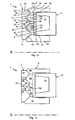
- FIGS. 1a and 1b schematically show an exemplary embodiment of the invention in the states of a non-switched clutch 1 in FIG. 1a and a switched clutch 1 in FIG. 1b ,
- the representation is limited to the essential components, the armature disk 2, the rotor 8, and the electromagnet 14 and shows only the contours of its cross section in the space above the axis of rotation S.
- the armature disk 2 consists of three soft-magnetic ring portions 3a, 3b, 3c, which are magnetically separated from each other by the slots 7a and 7b.
- the rotor 8 has four concentric soft-magnetic ring regions 9a, 9b, 9c and 9d.
- the outermost ring portion 9a and the innermost ring portion 9d are further extended in the axial direction so as to partially enclose the electric ring magnet 14 in a U-shaped profile.
- the soft magnetic annular regions of the rotor 9a, 9b, 9c, 9d are also magnetically isolated from each other by slots 13a, 13b and 13c.
- the coil turns 15 of the electromagnet 14 are de-energized, so that the armature disc 2 is held in a spaced position.
- the coil 15 is supplied with power.
- the electromagnet 14 generates a magnetic flux, which is guided in particular by the annular regions 9a and 9d of the rotor 8 at its working side.
- At its pole faces 10a, 10b, 10c, 10d, 10e and 10f an attractive effect is produced on the corresponding pole faces 4a, 4b, 4c, 4d, 4e and 4f of the armature disk 2.
- the pole faces 4a-4f of the armature disk 2 and those (10a to 10f) of the Rotor 8 at the same time take on the task of friction surfaces.
- the linear increase and decrease in the axial material thickness of the soft-magnetic annular regions 3a-3c, 9a-9d on both clutch discs 2, 8 indicates that the pole faces 4a-4f, 10a-10f are conical. All pole faces 4a - 4f, 10a - 10f are set at an angle to the axis of rotation S. Shown is an angle of about 45 °. Preferably, the pole faces are made at angles of less than 60 ° to the axis of rotation, with angles of 45 ° and smaller being more suitable. Anchoring angles of 30 ° and less, for example 27 °, are particularly preferred. The steeper salaried pole and friction surfaces engage each other like wedges, whereby the transmittable torque of the clutch is further increased. In order to avoid jamming of the clutch discs as possible, preferably attack angle of 20 ° and larger are used.
- Each soft-magnetic annular region, for example 3b, of the armature disk 2 is formed on the working side by two conical surfaces, e.g. 4c and 4d, limited, one of which faces the axis of rotation S and the other of the axis of rotation S faces away.
- the soft-magnetic annular regions 9a, 9b, 9c, 9d of the rotor 8 are bounded in a similar manner by pole faces, which are made to be accurate to the pole faces of the armature disk alternately to the axis of rotation S or repellent.
- the ring elements 9a and 9d each have only one pole face, since with their axial extension they concentrate the magnetic flux generated by the electromagnet 14 and lead to the working faces of the coupling disks 2, 8.
- the soft-magnetic ring regions 3a-3c, 9a-9d of the rotor 8 and the armature disk 2 are offset from each other so that the two clutch disks 2.8 are already in the separated state extend into each other.
- a pole face of the rotor 8, for example 10d, and a pole face of the armature disk 2, for example 4d face each other in pairs.
- the inner, for example, circular circumferential edge 6a of the pole face 4d abuts the magnetically separating region 7b, which forms a depression in the armature disk 2.
- the pole face 4d of the armature disk 2 adjoins the end face 5b, which restricts the axial elevation of the soft magnetic ring area 3b in the direction of the rotor.
- the pole face 10d of the rotor 8 is bounded at its outer edge 12a by the depression of the magnetically insulating region 13b and at its inner edge 12b by the end face 11b of the soft magnetic ring region 9c at the axially outermost elevation to the armature disk 2.
- the FIG. 1b shows that all polar surfaces are used at the same time as friction surfaces by a tailor-made design of the pole faces 4a - 4f and 10a - 10f on both clutch discs 2.8.
- the areas of maximum material thickness of the soft magnetic rings 3a - 3c, 9a - 9d extend in each case into the recess of the opposite clutch disc, on which the magnetically insulating slots 7a, 7b, 13a, 13b, 13c are located.
- the anchor plate 2 end faces 5a, 5b and 5c which adjoin the upper edge of the pole faces 4a, 4b, 4c, 4d, 4e and 4f. They cover the radial region of the slits 13a, 13b and 13c of the rotor disk.
- the slots of the armature disc 7a, 7b are superimposed by the end faces of the rotor 11a, 11b congruent.
- the clutch plates By accurately fitting the conical pole faces 4a - 4f, 10a - 10f and the flat end faces 5a - 5c, 11a, 11b of the rotor 8 and the armature disk 2, the clutch plates now get in frictional contact on all pole faces and at the same time offer a favorable path for the magnetic Flow, so that the friction surfaces 4a - 4f, 10a - 10f are pressed together with comparatively strong magnetic attraction forces. Due to the conical arrangement of the pole faces 4a - 4f, 10a - 10f, the two clutch plates 2,8 additionally give lateral support and align mechanically centered.
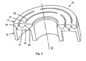
- the magnetic separation of the soft-magnetic annular regions are formed as a series of arcuate slots 20, so-called kidney slots, wherein between two slots 20 of the same radius each have a web-like connection 21 which mechanically connects two soft-magnetic annular regions. Therefore, in this radial region on the engaging clutch disc, the material thickness of the soft magnetic rings is limited by flat end faces. The flat end faces also avoid increased magnetic leakage flux through the slots 20.
Landscapes
- Engineering & Computer Science (AREA)
- General Engineering & Computer Science (AREA)
- Physics & Mathematics (AREA)
- Electromagnetism (AREA)
- Mechanical Engineering (AREA)
- Braking Arrangements (AREA)
- Mechanical Operated Clutches (AREA)
Claims (7)
- Embrayage à friction électromagnétique pourvu de deux disques d'embrayage (2, 8, 16) qui comportent plusieurs zones annulaires (3a-3c, 9a-9d, 19) en matériau magnétique doux et en cercles concentriques, lesquelles sont au moins partiellement isolées magnétiquement les unes des autres, un disque d'embrayage comportant un disque d'induit (2, 17) axialement mobile qui présente au moins une zone annulaire (3a-3c,19) magnétiquement conductrice reliant magnétiquement deux zones annulaires (9a-9d, 19) magnétiquement isolées du second disque d'embrayage (8, 18), caractérisé en ce que les disques d'embrayage (2, 8, 16) présentent, une vue en coupe radiale, des surfaces polaires (4a-4f, 10a-10f) oscillantes sur les zones annulaires (3a-3c, 9a-9d, 19) en matériau magnétique doux, lesquelles sont conçues au moins partiellement comme des surfaces de friction (4a-4f, 10a-10f), et par l'intermédiaire desquelles une attraction se produit lorsque l'embrayage est embrayé, les profils en coupe radiale des deux disques d'embrayage (2, 8, 16) étant adaptés les uns aux autres avec précision au moins dans la zone des surfaces de friction (4a-4f, 10a-10f).
- Embrayage à friction électromagnétique selon la revendication 1, caractérisé en ce que les disques d'embrayage (2, 8, 16) présentent dans le tracé en coupe radiale des zones annulaires (3a-3c, 9a-9d, 19) en matériau magnétique doux respectivement un maximum dans la direction axiale, qui se dresse en direction du disque d'embrayage opposé.
- Embrayage à friction électromagnétique selon l'une quelconque des revendications précédentes, caractérisé en ce que les zones annulaires (3a-3c, 9a-9d, 19) en matériau magnétique doux présentent des surfaces polaires coniques (4a-4f, 10a-10f).
- Embrayage à friction électromagnétique selon l'une quelconque des revendications précédentes, caractérisé en ce que les zones annulaires (3a-3c, 9a-9d, 19) en matériau magnétique doux d'un disque d'embrayage (2, 8, 17, 18) sont séparées les unes des autres sur toute la circonférence par des fentes (7a-7b, 13a-13c, 20) et en ce que les zones annulaires (3a-3c, 9a-9d, 19) sont solidarisées mécaniquement à demeure dans la direction radiale par des éléments de liaison (21).
- Embrayage à friction électromagnétique selon l'une quelconque des revendications précédentes, caractérisé en ce que la partie surélevée axialement la plus extérieure d'une zone annulaire (3a-3c, 9a-9d, 19) en matériau magnétique doux d'un disque d'embrayage (2, 8, 17, 18) parvient au maximum jusqu'au bord axialement le plus intérieur d'une surface polaire (4a-4f, 10a-10f) et/ou d'une surface de friction dans le creux du disque d'embrayage opposé, lorsque les disques d'embrayage (2, 8, 16) sont en contact de friction les uns avec les autres.
- Embrayage à friction électromagnétique selon l'une quelconque des revendications précédentes, caractérisé en ce que le bord axialement le plus profond d'une surface polaire et/ou d'une surface de friction (4a-4f, 10a-10f) d'une zone annulaire (3a-3c, 9a-9d, 19) en matériau magnétique doux dans un disque d'embrayage (2, 8, 17, 18) bute contre le bord d'une zone magnétiquement isolante (7a-7b, 13a-13c, 20) du disque d'embrayage.
- Embrayage à friction électromagnétique selon l'une quelconque des revendications précédentes, caractérisé en ce qu'un matériau solide magnétiquement isolant est introduit entre des zones annulaires (3a-3c, 9a-9d, 19) en matériau magnétique doux d'un disque d'embrayage (2, 8, 17, 18) et une surface de friction est formée au moins partiellement dans la zone magnétiquement isolante (7a-7b, 13a-13c).
Applications Claiming Priority (2)
| Application Number | Priority Date | Filing Date | Title |
|---|---|---|---|
| DE102009019139A DE102009019139A1 (de) | 2009-04-29 | 2009-04-29 | Elektromagnetische Reibungskupplung mit oszillierenden Polflächen |
| PCT/EP2010/000181 WO2010124749A1 (fr) | 2009-04-29 | 2010-01-15 | Embrayage à friction électromagnétique à faces polaires oscillantes |
Publications (2)
| Publication Number | Publication Date |
|---|---|
| EP2425141A1 EP2425141A1 (fr) | 2012-03-07 |
| EP2425141B1 true EP2425141B1 (fr) | 2013-11-06 |
Family
ID=42060873
Family Applications (1)
| Application Number | Title | Priority Date | Filing Date |
|---|---|---|---|
| EP10700709.8A Not-in-force EP2425141B1 (fr) | 2009-04-29 | 2010-01-15 | Embrayage à friction électromagnétique à faces polaires oscillantes |
Country Status (5)
| Country | Link |
|---|---|
| US (1) | US8839931B2 (fr) |
| EP (1) | EP2425141B1 (fr) |
| CN (1) | CN102422042A (fr) |
| DE (1) | DE102009019139A1 (fr) |
| WO (1) | WO2010124749A1 (fr) |
Families Citing this family (5)
| Publication number | Priority date | Publication date | Assignee | Title |
|---|---|---|---|---|
| DE202011001197U1 (de) | 2010-10-14 | 2012-01-17 | Eto Magnetic Gmbh | Magnetisch optimierte Reibkupplung |
| JP2014095402A (ja) * | 2012-11-08 | 2014-05-22 | Denso Corp | 電磁クラッチ、電磁クラッチの制御装置及び電磁クラッチの制御方法 |
| WO2014074438A1 (fr) * | 2012-11-12 | 2014-05-15 | Borgwarner Inc. | Ensemble solénoïde pour embrayage à friction |
| DE102014109125B4 (de) * | 2014-06-30 | 2016-09-29 | Kendrion (Villingen) Gmbh | Elektromagnetische Polreibungskupplung oder Polreibungsbremse |
| CN108644250A (zh) * | 2018-07-27 | 2018-10-12 | 合肥研新离合器有限公司 | 一种摩擦离合器用双效挤压结构 |
Family Cites Families (15)
| Publication number | Priority date | Publication date | Assignee | Title |
|---|---|---|---|---|
| US566508A (en) * | 1896-08-25 | Friction-clutch | ||
| US1756907A (en) * | 1928-06-09 | 1930-04-29 | Goodwin Hall J | Electromagnetic clutch |
| US3214084A (en) * | 1961-03-27 | 1965-10-26 | Borg Warner | Electromagnetic friction device and compressor control for same |
| US3451516A (en) * | 1968-01-12 | 1969-06-24 | Rca Corp | Electromagnetic clutch having eccentrically mounted poles |
| DE2055678B1 (de) | 1970-11-12 | 1972-03-09 | Heinemann R | Bremse oder Kupplung |
| JPS60205026A (ja) * | 1984-03-28 | 1985-10-16 | Ogura Clutch Co Ltd | 電磁連結装置 |
| JPS6249025A (ja) * | 1985-08-27 | 1987-03-03 | Sanden Corp | 電磁クラツチ |
| EP0216514B1 (fr) | 1985-08-23 | 1990-11-14 | Sanden Corporation | Embrayages électromagnétiques |
| JPH0357526U (fr) * | 1989-10-12 | 1991-06-03 | ||
| US5125255A (en) | 1991-06-27 | 1992-06-30 | Dana Corporation | Method of making an electromagnetic coupling disc |
| JP2001200861A (ja) | 2000-01-14 | 2001-07-27 | Mitsubishi Heavy Ind Ltd | 電磁クラッチ |
| DE202004009184U1 (de) | 2004-06-11 | 2004-10-07 | Linnig Antriebstechnik Gmbh | Elektromagnetisch betätigbare Reibscheibenkupplung |
| DE102004042687B4 (de) * | 2004-09-01 | 2009-04-16 | Linnig Trucktec Gmbh | Elektromagnetisch betätigbare Reibscheibenkupplung und Rotor für eine solche Kupplung |
| DE102005025546A1 (de) | 2005-06-01 | 2006-12-07 | Kern Gmbh | Kupplungs-Bremskombination |
| US20100025131A1 (en) * | 2006-04-03 | 2010-02-04 | Bluwav Systems, Llc | Electric propulsion system |
-
2009
- 2009-04-29 DE DE102009019139A patent/DE102009019139A1/de not_active Withdrawn
-
2010
- 2010-01-15 EP EP10700709.8A patent/EP2425141B1/fr not_active Not-in-force
- 2010-01-15 CN CN2010800190491A patent/CN102422042A/zh active Pending
- 2010-01-15 US US13/266,216 patent/US8839931B2/en not_active Expired - Fee Related
- 2010-01-15 WO PCT/EP2010/000181 patent/WO2010124749A1/fr not_active Ceased
Also Published As
| Publication number | Publication date |
|---|---|
| US20120132494A1 (en) | 2012-05-31 |
| EP2425141A1 (fr) | 2012-03-07 |
| CN102422042A (zh) | 2012-04-18 |
| US8839931B2 (en) | 2014-09-23 |
| DE102009019139A1 (de) | 2010-11-04 |
| WO2010124749A1 (fr) | 2010-11-04 |
Similar Documents
| Publication | Publication Date | Title |
|---|---|---|
| DE3704643C2 (fr) | ||
| EP2150717B2 (fr) | Dispositif de transmission de couple magnétorhéologique, son procédé d'utilisation, et procédé de transmission de couple magnétorhéologique associé | |
| DE69917228T2 (de) | Riemenscheibe mit elektromagnetischer kupplung | |
| EP1989460A1 (fr) | Carter d'embrayage comportant des ouvertures pour la réception d'un disque d'embrayage | |
| DE2911874A1 (de) | Elektromagnetische kupplung und verfahren zu ihrer herstellung | |
| EP2855969A1 (fr) | Elément d'équilibrage et procédé d'équilibrage d'un embrayage | |
| EP2425141A1 (fr) | Embrayage à friction électromagnétique à faces polaires oscillantes | |
| DE10106802B4 (de) | Einweg-Kupplung | |
| AT516124A1 (de) | Reiblamelle | |
| WO2012150093A1 (fr) | Amortisseur de vibrations torsionnelles | |
| EP2422103B1 (fr) | Procédé de fabrication de disques d'embrayage et de frein pour embrayages électromagnétiques ou freins électromagnétiques présentant au moins un élément à surface de friction | |
| DE102016223033A1 (de) | Kupplungseinrichtung | |
| DE2932661A1 (de) | Kupplung | |
| DE102018122194A1 (de) | Kupplungseinrichtung | |
| DE2538494B2 (de) | Elektromagnetisch betätigbare Reibscheiben-Kupplung oder -Bremse | |
| DE102019005799A1 (de) | Drehtisch | |
| DE102014109125B4 (de) | Elektromagnetische Polreibungskupplung oder Polreibungsbremse | |
| EP1966519A2 (fr) | Embrayage monte sur le bord exterieur d'un convertisseur de couple et procede pour integrer un embrayage dans un convertisseur de couple | |
| DE69403161T2 (de) | Einweg-Kupplung eingliedernd einen Haltering aufweisend gepaarte symmetrische Verbindungsteile | |
| DE102016215295A1 (de) | Fliehkraftpendel | |
| DE102006007688B4 (de) | Elektromagnetisch betätigbare Schalteinheit | |
| DE1924458A1 (de) | Elektromagnetische Kupplung | |
| WO2018068782A1 (fr) | Ensemble embrayage | |
| EP3874174A1 (fr) | Embrayage à friction | |
| DE102019127553A1 (de) | Dynamische Dämpfungsvorrichtung |
Legal Events
| Date | Code | Title | Description |
|---|---|---|---|
| PUAI | Public reference made under article 153(3) epc to a published international application that has entered the european phase |
Free format text: ORIGINAL CODE: 0009012 |
|
| 17P | Request for examination filed |
Effective date: 20110318 |
|
| AK | Designated contracting states |
Kind code of ref document: A1 Designated state(s): AT BE BG CH CY CZ DE DK EE ES FI FR GB GR HR HU IE IS IT LI LT LU LV MC MK MT NL NO PL PT RO SE SI SK SM TR |
|
| DAX | Request for extension of the european patent (deleted) | ||
| REG | Reference to a national code |
Ref country code: DE Ref legal event code: R079 Ref document number: 502010005272 Country of ref document: DE Free format text: PREVIOUS MAIN CLASS: F16D0027110000 Ipc: F16D0027112000 |
|
| RIC1 | Information provided on ipc code assigned before grant |
Ipc: F16D 27/112 20060101AFI20120913BHEP Ipc: F16D 27/11 20060101ALI20120913BHEP |
|
| 17Q | First examination report despatched |
Effective date: 20120924 |
|
| GRAP | Despatch of communication of intention to grant a patent |
Free format text: ORIGINAL CODE: EPIDOSNIGR1 |
|
| INTG | Intention to grant announced |
Effective date: 20130617 |
|
| GRAS | Grant fee paid |
Free format text: ORIGINAL CODE: EPIDOSNIGR3 |
|
| GRAA | (expected) grant |
Free format text: ORIGINAL CODE: 0009210 |
|
| AK | Designated contracting states |
Kind code of ref document: B1 Designated state(s): AT BE BG CH CY CZ DE DK EE ES FI FR GB GR HR HU IE IS IT LI LT LU LV MC MK MT NL NO PL PT RO SE SI SK SM TR |
|
| REG | Reference to a national code |
Ref country code: GB Ref legal event code: FG4D Free format text: NOT ENGLISH |
|
| REG | Reference to a national code |
Ref country code: CH Ref legal event code: EP |
|
| REG | Reference to a national code |
Ref country code: AT Ref legal event code: REF Ref document number: 639707 Country of ref document: AT Kind code of ref document: T Effective date: 20131215 |
|
| REG | Reference to a national code |
Ref country code: IE Ref legal event code: FG4D Free format text: LANGUAGE OF EP DOCUMENT: GERMAN |
|
| REG | Reference to a national code |
Ref country code: DE Ref legal event code: R096 Ref document number: 502010005272 Country of ref document: DE Effective date: 20140102 |
|
| REG | Reference to a national code |
Ref country code: NL Ref legal event code: VDEP Effective date: 20131106 |
|
| REG | Reference to a national code |
Ref country code: LT Ref legal event code: MG4D |
|
| PG25 | Lapsed in a contracting state [announced via postgrant information from national office to epo] |
Ref country code: SE Free format text: LAPSE BECAUSE OF FAILURE TO SUBMIT A TRANSLATION OF THE DESCRIPTION OR TO PAY THE FEE WITHIN THE PRESCRIBED TIME-LIMIT Effective date: 20131106 Ref country code: HR Free format text: LAPSE BECAUSE OF FAILURE TO SUBMIT A TRANSLATION OF THE DESCRIPTION OR TO PAY THE FEE WITHIN THE PRESCRIBED TIME-LIMIT Effective date: 20131106 Ref country code: LT Free format text: LAPSE BECAUSE OF FAILURE TO SUBMIT A TRANSLATION OF THE DESCRIPTION OR TO PAY THE FEE WITHIN THE PRESCRIBED TIME-LIMIT Effective date: 20131106 Ref country code: NL Free format text: LAPSE BECAUSE OF FAILURE TO SUBMIT A TRANSLATION OF THE DESCRIPTION OR TO PAY THE FEE WITHIN THE PRESCRIBED TIME-LIMIT Effective date: 20131106 Ref country code: NO Free format text: LAPSE BECAUSE OF FAILURE TO SUBMIT A TRANSLATION OF THE DESCRIPTION OR TO PAY THE FEE WITHIN THE PRESCRIBED TIME-LIMIT Effective date: 20140206 Ref country code: FI Free format text: LAPSE BECAUSE OF FAILURE TO SUBMIT A TRANSLATION OF THE DESCRIPTION OR TO PAY THE FEE WITHIN THE PRESCRIBED TIME-LIMIT Effective date: 20131106 Ref country code: IS Free format text: LAPSE BECAUSE OF FAILURE TO SUBMIT A TRANSLATION OF THE DESCRIPTION OR TO PAY THE FEE WITHIN THE PRESCRIBED TIME-LIMIT Effective date: 20140306 |
|
| PG25 | Lapsed in a contracting state [announced via postgrant information from national office to epo] |
Ref country code: ES Free format text: LAPSE BECAUSE OF FAILURE TO SUBMIT A TRANSLATION OF THE DESCRIPTION OR TO PAY THE FEE WITHIN THE PRESCRIBED TIME-LIMIT Effective date: 20131106 Ref country code: LV Free format text: LAPSE BECAUSE OF FAILURE TO SUBMIT A TRANSLATION OF THE DESCRIPTION OR TO PAY THE FEE WITHIN THE PRESCRIBED TIME-LIMIT Effective date: 20131106 |
|
| PG25 | Lapsed in a contracting state [announced via postgrant information from national office to epo] |
Ref country code: PT Free format text: LAPSE BECAUSE OF FAILURE TO SUBMIT A TRANSLATION OF THE DESCRIPTION OR TO PAY THE FEE WITHIN THE PRESCRIBED TIME-LIMIT Effective date: 20140306 |
|
| BERE | Be: lapsed |
Owner name: KENDRION LINNIG G.M.B.H. Effective date: 20140131 |
|
| PG25 | Lapsed in a contracting state [announced via postgrant information from national office to epo] |
Ref country code: EE Free format text: LAPSE BECAUSE OF FAILURE TO SUBMIT A TRANSLATION OF THE DESCRIPTION OR TO PAY THE FEE WITHIN THE PRESCRIBED TIME-LIMIT Effective date: 20131106 |
|
| REG | Reference to a national code |
Ref country code: DE Ref legal event code: R097 Ref document number: 502010005272 Country of ref document: DE |
|
| PG25 | Lapsed in a contracting state [announced via postgrant information from national office to epo] |
Ref country code: LU Free format text: LAPSE BECAUSE OF FAILURE TO SUBMIT A TRANSLATION OF THE DESCRIPTION OR TO PAY THE FEE WITHIN THE PRESCRIBED TIME-LIMIT Effective date: 20140115 Ref country code: CZ Free format text: LAPSE BECAUSE OF FAILURE TO SUBMIT A TRANSLATION OF THE DESCRIPTION OR TO PAY THE FEE WITHIN THE PRESCRIBED TIME-LIMIT Effective date: 20131106 Ref country code: IT Free format text: LAPSE BECAUSE OF FAILURE TO SUBMIT A TRANSLATION OF THE DESCRIPTION OR TO PAY THE FEE WITHIN THE PRESCRIBED TIME-LIMIT Effective date: 20131106 Ref country code: PL Free format text: LAPSE BECAUSE OF FAILURE TO SUBMIT A TRANSLATION OF THE DESCRIPTION OR TO PAY THE FEE WITHIN THE PRESCRIBED TIME-LIMIT Effective date: 20131106 Ref country code: RO Free format text: LAPSE BECAUSE OF FAILURE TO SUBMIT A TRANSLATION OF THE DESCRIPTION OR TO PAY THE FEE WITHIN THE PRESCRIBED TIME-LIMIT Effective date: 20131106 Ref country code: SK Free format text: LAPSE BECAUSE OF FAILURE TO SUBMIT A TRANSLATION OF THE DESCRIPTION OR TO PAY THE FEE WITHIN THE PRESCRIBED TIME-LIMIT Effective date: 20131106 |
|
| REG | Reference to a national code |
Ref country code: CH Ref legal event code: PL |
|
| PLBE | No opposition filed within time limit |
Free format text: ORIGINAL CODE: 0009261 |
|
| STAA | Information on the status of an ep patent application or granted ep patent |
Free format text: STATUS: NO OPPOSITION FILED WITHIN TIME LIMIT |
|
| PG25 | Lapsed in a contracting state [announced via postgrant information from national office to epo] |
Ref country code: DK Free format text: LAPSE BECAUSE OF FAILURE TO SUBMIT A TRANSLATION OF THE DESCRIPTION OR TO PAY THE FEE WITHIN THE PRESCRIBED TIME-LIMIT Effective date: 20131106 |
|
| 26N | No opposition filed |
Effective date: 20140807 |
|
| GBPC | Gb: european patent ceased through non-payment of renewal fee |
Effective date: 20140206 |
|
| PG25 | Lapsed in a contracting state [announced via postgrant information from national office to epo] |
Ref country code: CH Free format text: LAPSE BECAUSE OF NON-PAYMENT OF DUE FEES Effective date: 20140131 Ref country code: LI Free format text: LAPSE BECAUSE OF NON-PAYMENT OF DUE FEES Effective date: 20140131 |
|
| REG | Reference to a national code |
Ref country code: FR Ref legal event code: ST Effective date: 20140930 |
|
| REG | Reference to a national code |
Ref country code: IE Ref legal event code: MM4A |
|
| REG | Reference to a national code |
Ref country code: DE Ref legal event code: R097 Ref document number: 502010005272 Country of ref document: DE Effective date: 20140807 |
|
| PG25 | Lapsed in a contracting state [announced via postgrant information from national office to epo] |
Ref country code: FR Free format text: LAPSE BECAUSE OF NON-PAYMENT OF DUE FEES Effective date: 20140131 |
|
| PG25 | Lapsed in a contracting state [announced via postgrant information from national office to epo] |
Ref country code: IE Free format text: LAPSE BECAUSE OF NON-PAYMENT OF DUE FEES Effective date: 20140115 Ref country code: GB Free format text: LAPSE BECAUSE OF NON-PAYMENT OF DUE FEES Effective date: 20140206 Ref country code: BE Free format text: LAPSE BECAUSE OF NON-PAYMENT OF DUE FEES Effective date: 20140131 |
|
| PG25 | Lapsed in a contracting state [announced via postgrant information from national office to epo] |
Ref country code: SI Free format text: LAPSE BECAUSE OF FAILURE TO SUBMIT A TRANSLATION OF THE DESCRIPTION OR TO PAY THE FEE WITHIN THE PRESCRIBED TIME-LIMIT Effective date: 20131106 |
|
| PG25 | Lapsed in a contracting state [announced via postgrant information from national office to epo] |
Ref country code: MC Free format text: LAPSE BECAUSE OF FAILURE TO SUBMIT A TRANSLATION OF THE DESCRIPTION OR TO PAY THE FEE WITHIN THE PRESCRIBED TIME-LIMIT Effective date: 20131106 |
|
| PG25 | Lapsed in a contracting state [announced via postgrant information from national office to epo] |
Ref country code: MT Free format text: LAPSE BECAUSE OF FAILURE TO SUBMIT A TRANSLATION OF THE DESCRIPTION OR TO PAY THE FEE WITHIN THE PRESCRIBED TIME-LIMIT Effective date: 20131106 |
|
| REG | Reference to a national code |
Ref country code: AT Ref legal event code: MM01 Ref document number: 639707 Country of ref document: AT Kind code of ref document: T Effective date: 20150115 |
|
| PG25 | Lapsed in a contracting state [announced via postgrant information from national office to epo] |
Ref country code: SM Free format text: LAPSE BECAUSE OF FAILURE TO SUBMIT A TRANSLATION OF THE DESCRIPTION OR TO PAY THE FEE WITHIN THE PRESCRIBED TIME-LIMIT Effective date: 20131106 |
|
| PGFP | Annual fee paid to national office [announced via postgrant information from national office to epo] |
Ref country code: TR Payment date: 20160107 Year of fee payment: 7 Ref country code: DE Payment date: 20160308 Year of fee payment: 7 |
|
| PG25 | Lapsed in a contracting state [announced via postgrant information from national office to epo] |
Ref country code: AT Free format text: LAPSE BECAUSE OF NON-PAYMENT OF DUE FEES Effective date: 20150115 |
|
| PG25 | Lapsed in a contracting state [announced via postgrant information from national office to epo] |
Ref country code: CY Free format text: LAPSE BECAUSE OF FAILURE TO SUBMIT A TRANSLATION OF THE DESCRIPTION OR TO PAY THE FEE WITHIN THE PRESCRIBED TIME-LIMIT Effective date: 20131106 Ref country code: BG Free format text: LAPSE BECAUSE OF FAILURE TO SUBMIT A TRANSLATION OF THE DESCRIPTION OR TO PAY THE FEE WITHIN THE PRESCRIBED TIME-LIMIT Effective date: 20131106 Ref country code: GR Free format text: LAPSE BECAUSE OF FAILURE TO SUBMIT A TRANSLATION OF THE DESCRIPTION OR TO PAY THE FEE WITHIN THE PRESCRIBED TIME-LIMIT Effective date: 20140207 |
|
| PG25 | Lapsed in a contracting state [announced via postgrant information from national office to epo] |
Ref country code: HU Free format text: LAPSE BECAUSE OF FAILURE TO SUBMIT A TRANSLATION OF THE DESCRIPTION OR TO PAY THE FEE WITHIN THE PRESCRIBED TIME-LIMIT; INVALID AB INITIO Effective date: 20100115 |
|
| REG | Reference to a national code |
Ref country code: DE Ref legal event code: R119 Ref document number: 502010005272 Country of ref document: DE |
|
| PG25 | Lapsed in a contracting state [announced via postgrant information from national office to epo] |
Ref country code: DE Free format text: LAPSE BECAUSE OF NON-PAYMENT OF DUE FEES Effective date: 20170801 |
|
| PG25 | Lapsed in a contracting state [announced via postgrant information from national office to epo] |
Ref country code: MK Free format text: LAPSE BECAUSE OF FAILURE TO SUBMIT A TRANSLATION OF THE DESCRIPTION OR TO PAY THE FEE WITHIN THE PRESCRIBED TIME-LIMIT Effective date: 20131106 |
|
| PG25 | Lapsed in a contracting state [announced via postgrant information from national office to epo] |
Ref country code: TR Free format text: LAPSE BECAUSE OF NON-PAYMENT OF DUE FEES Effective date: 20170115 |