EP2425141B1 - Electromagnetic friction clutch having oscillating pole faces - Google Patents
Electromagnetic friction clutch having oscillating pole faces Download PDFInfo
- Publication number
- EP2425141B1 EP2425141B1 EP10700709.8A EP10700709A EP2425141B1 EP 2425141 B1 EP2425141 B1 EP 2425141B1 EP 10700709 A EP10700709 A EP 10700709A EP 2425141 B1 EP2425141 B1 EP 2425141B1
- Authority
- EP
- European Patent Office
- Prior art keywords
- clutch
- soft magnetic
- friction
- disk
- magnetically
- Prior art date
- Legal status (The legal status is an assumption and is not a legal conclusion. Google has not performed a legal analysis and makes no representation as to the accuracy of the status listed.)
- Not-in-force
Links
- 239000000463 material Substances 0.000 claims description 7
- 239000007787 solid Substances 0.000 claims 1
- 230000004907 flux Effects 0.000 description 12
- 230000008878 coupling Effects 0.000 description 6
- 238000010168 coupling process Methods 0.000 description 6
- 238000005859 coupling reaction Methods 0.000 description 6
- 230000000630 rising effect Effects 0.000 description 3
- 230000000694 effects Effects 0.000 description 2
- 230000002349 favourable effect Effects 0.000 description 2
- 238000004873 anchoring Methods 0.000 description 1
- 230000005540 biological transmission Effects 0.000 description 1
- 239000012141 concentrate Substances 0.000 description 1
- 230000003247 decreasing effect Effects 0.000 description 1
- 230000001419 dependent effect Effects 0.000 description 1
- 238000011161 development Methods 0.000 description 1
- 230000018109 developmental process Effects 0.000 description 1
- 239000011810 insulating material Substances 0.000 description 1
- 238000002955 isolation Methods 0.000 description 1
- 210000003734 kidney Anatomy 0.000 description 1
- 238000007885 magnetic separation Methods 0.000 description 1
- 238000004519 manufacturing process Methods 0.000 description 1
- 230000010355 oscillation Effects 0.000 description 1
- 230000002093 peripheral effect Effects 0.000 description 1
- 230000002940 repellent Effects 0.000 description 1
- 239000005871 repellent Substances 0.000 description 1
- 230000035939 shock Effects 0.000 description 1
- 238000004513 sizing Methods 0.000 description 1
Images
Classifications
-
- F—MECHANICAL ENGINEERING; LIGHTING; HEATING; WEAPONS; BLASTING
- F16—ENGINEERING ELEMENTS AND UNITS; GENERAL MEASURES FOR PRODUCING AND MAINTAINING EFFECTIVE FUNCTIONING OF MACHINES OR INSTALLATIONS; THERMAL INSULATION IN GENERAL
- F16D—COUPLINGS FOR TRANSMITTING ROTATION; CLUTCHES; BRAKES
- F16D27/00—Magnetically- or electrically- actuated clutches; Control or electric circuits therefor
- F16D27/10—Magnetically- or electrically- actuated clutches; Control or electric circuits therefor with an electromagnet not rotating with a clutching member, i.e. without collecting rings
- F16D27/108—Magnetically- or electrically- actuated clutches; Control or electric circuits therefor with an electromagnet not rotating with a clutching member, i.e. without collecting rings with axially movable clutching members
- F16D27/112—Magnetically- or electrically- actuated clutches; Control or electric circuits therefor with an electromagnet not rotating with a clutching member, i.e. without collecting rings with axially movable clutching members with flat friction surfaces, e.g. discs
-
- F—MECHANICAL ENGINEERING; LIGHTING; HEATING; WEAPONS; BLASTING
- F16—ENGINEERING ELEMENTS AND UNITS; GENERAL MEASURES FOR PRODUCING AND MAINTAINING EFFECTIVE FUNCTIONING OF MACHINES OR INSTALLATIONS; THERMAL INSULATION IN GENERAL
- F16D—COUPLINGS FOR TRANSMITTING ROTATION; CLUTCHES; BRAKES
- F16D27/00—Magnetically- or electrically- actuated clutches; Control or electric circuits therefor
- F16D27/10—Magnetically- or electrically- actuated clutches; Control or electric circuits therefor with an electromagnet not rotating with a clutching member, i.e. without collecting rings
- F16D27/108—Magnetically- or electrically- actuated clutches; Control or electric circuits therefor with an electromagnet not rotating with a clutching member, i.e. without collecting rings with axially movable clutching members
- F16D27/11—Magnetically- or electrically- actuated clutches; Control or electric circuits therefor with an electromagnet not rotating with a clutching member, i.e. without collecting rings with axially movable clutching members with conical friction surfaces, e.g. cone clutches
-
- F—MECHANICAL ENGINEERING; LIGHTING; HEATING; WEAPONS; BLASTING
- F16—ENGINEERING ELEMENTS AND UNITS; GENERAL MEASURES FOR PRODUCING AND MAINTAINING EFFECTIVE FUNCTIONING OF MACHINES OR INSTALLATIONS; THERMAL INSULATION IN GENERAL
- F16D—COUPLINGS FOR TRANSMITTING ROTATION; CLUTCHES; BRAKES
- F16D27/00—Magnetically- or electrically- actuated clutches; Control or electric circuits therefor
- F16D2027/008—Details relating to the magnetic circuit, or to the shape of the clutch parts to achieve a certain magnetic path
Definitions
- the invention relates to an electromagnetic friction clutch according to the preamble of claim 1.
- a generic friction clutch is off EP 0 216 514 known.
- the invention has for its object to provide a coupling which transmits a comparatively increased maximum torque in a space-saving design.
- the invention is based on an electromagnetic friction clutch with two clutch plates, wherein a Clutch disc comprises an axially movable armature disc.
- the clutch discs have a plurality of concentric circular soft-magnetic ring areas, which are at least partially magnetically isolated from each other.
- the axially movable armature disk has at least one magnetically conductive annular region which magnetically connects two magnetically isolated annular regions of the two clutch disk.
- the essence of the invention consists in the fact that the clutch discs viewed in radial cross-section, having oscillating pole faces on the soft magnetic annular regions, which are at least partially formed as friction surfaces, and via which an attraction takes place in a switching of the clutch, wherein the radial cross-sectional profile of both coupling letters at least in the area of friction surfaces is precisely matched to each other.
- the side of a clutch disc which is turned to the respective opposite clutch disc, referred to as the working side.
- the oscillation of the pole faces is to be understood such that the coupling disks have on the surface of their respective working side in cross-section a profile which alternately has increasing and decreasing areas in the axial direction with increasing radius. This causes the surfaces of the clutch discs on their working side show concentric elevations or depressions.
- the surface profile of the clutch disks is preferably predominantly uniformly smooth around the axis of rotation, in particular in areas in which the clutch disks contact each other in the engaged state.
- the rotational symmetry of the clutch discs on the working side can be disturbed in areas which are axially reset in particular with respect to the friction surfaces.
- Opposite planar pole faces of the axially oscillating over the radius profile has the advantage that the area over which a magnetic attraction can take place is increased.
- the oscillating pole faces offer the advantage that the adhesion to shocks and vibrations perpendicular to the axis of rotation becomes less sensitive.
- the soft magnetic annular regions of a clutch disc between magnetic insulating means of a ring portion of a clutch disc in the cross-sectional profile have a maximum in the axial direction.
- the soft-magnetic annular regions advantageously receive an axial cross-sectional profile which, with increasing radius, has a rising and a falling flank in the axial direction and forms a maximum between these flanks.
- the magnetically conductive regions can be predetermined for a mutual engagement of the clutch discs, wherein the flanks act at least partially as pole faces.
- the pole faces at least partially form friction surfaces. Because of the strongest attraction on the pole faces, the magnetic pole faces provide the best conditions for torque transmission through frictional contact.
- the radial cross-sectional profile of the two clutch discs is matched precisely to one another. This offers on the one hand the advantage that the magnetic pole faces in a separate position the two clutch plates can be kept at a small distance. When switching on, for example, the electromagnet, therefore strong forces and enable a quick connection of the clutch. Furthermore, the tailor-made design of the coupling surfaces, that the available surface area can be optimally used for the Reibungskraft gleich.
- the soft-magnetic ring areas have conical pole faces. This offers the advantage that the pole faces can be made particularly simple and accurate.
- the conical pole faces preferably appear as flanks rising or falling in the axial direction in relation to the opposite clutch disc. This makes it easier to calculate their sizing.
- a further preferred embodiment of the invention is characterized in that the soft-magnetic ring areas of a clutch disc are circumferentially separated from one another by gaps and that the ring areas are mechanically fixed to one another by webs in the radial direction.
- the magnetic isolation of the soft magnetic annular regions is e.g. in this case essentially by material removal, for example, cut, produced.
- material which is provided for the fixed mechanical connection of the soft-magnetic annular areas with one another can be excluded from the material removal.
- the structures of these clutch discs can be dimensioned so that only a few or no further processing steps are necessary for their production. At the same time weight and moment of inertia of the clutch plates are advantageously reduced, thereby improving their switching behavior.
- the axially lower edge of a pole and / or friction surface of a soft-magnetic annular region of a clutch disc abuts the edge of a magnetically insulating region in the clutch disc. Consequently, the insulating regions are one Clutch disc in the recesses of their working side. Because the magnetic flux is transmitted substantially through the pole faces at the rising and falling edges of the soft magnetic regions, this arrangement of the insulating regions offers the advantage that the magnetic flux is conducted past the insulating regions and thus only a small leakage by leakage flux over the insulating areas can arise.
- the axially outermost elevation of a soft-magnetic annular region of a clutch disk only extends to the axially lowest edge of a pole surface and / or friction surface of the opposite clutch disk when the clutch disks are in frictional contact with one another.
- the clutch discs preferably engage with each other so that they form a central region in the axial direction, which can flow through the magnetic flux with relatively small changes in direction.
- the axial range of the soft magnetic regions in the opposite clutch disc can be limited in this case such that no or hardly any leakage flux can arise at the insulating regions, which reduces the magnetic attraction at the pole faces.
- this measure also improves the efficiency of the clutch.
- a further expedient embodiment of the invention provides that between magnetically soft annular regions of a clutch disc fixed magnetically insulating material is introduced and in the magnetically insulating region at least partially a friction surface is formed. In this way, the friction surface can be further increased and thus the transmittable torque can be advantageously increased.
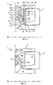
- FIGS. 1a and 1b schematically show an exemplary embodiment of the invention in the states of a non-switched clutch 1 in FIG. 1a and a switched clutch 1 in FIG. 1b ,
- the representation is limited to the essential components, the armature disk 2, the rotor 8, and the electromagnet 14 and shows only the contours of its cross section in the space above the axis of rotation S.
- the armature disk 2 consists of three soft-magnetic ring portions 3a, 3b, 3c, which are magnetically separated from each other by the slots 7a and 7b.
- the rotor 8 has four concentric soft-magnetic ring regions 9a, 9b, 9c and 9d.
- the outermost ring portion 9a and the innermost ring portion 9d are further extended in the axial direction so as to partially enclose the electric ring magnet 14 in a U-shaped profile.
- the soft magnetic annular regions of the rotor 9a, 9b, 9c, 9d are also magnetically isolated from each other by slots 13a, 13b and 13c.
- the coil turns 15 of the electromagnet 14 are de-energized, so that the armature disc 2 is held in a spaced position.
- the coil 15 is supplied with power.
- the electromagnet 14 generates a magnetic flux, which is guided in particular by the annular regions 9a and 9d of the rotor 8 at its working side.
- At its pole faces 10a, 10b, 10c, 10d, 10e and 10f an attractive effect is produced on the corresponding pole faces 4a, 4b, 4c, 4d, 4e and 4f of the armature disk 2.
- the pole faces 4a-4f of the armature disk 2 and those (10a to 10f) of the Rotor 8 at the same time take on the task of friction surfaces.
- the linear increase and decrease in the axial material thickness of the soft-magnetic annular regions 3a-3c, 9a-9d on both clutch discs 2, 8 indicates that the pole faces 4a-4f, 10a-10f are conical. All pole faces 4a - 4f, 10a - 10f are set at an angle to the axis of rotation S. Shown is an angle of about 45 °. Preferably, the pole faces are made at angles of less than 60 ° to the axis of rotation, with angles of 45 ° and smaller being more suitable. Anchoring angles of 30 ° and less, for example 27 °, are particularly preferred. The steeper salaried pole and friction surfaces engage each other like wedges, whereby the transmittable torque of the clutch is further increased. In order to avoid jamming of the clutch discs as possible, preferably attack angle of 20 ° and larger are used.
- Each soft-magnetic annular region, for example 3b, of the armature disk 2 is formed on the working side by two conical surfaces, e.g. 4c and 4d, limited, one of which faces the axis of rotation S and the other of the axis of rotation S faces away.
- the soft-magnetic annular regions 9a, 9b, 9c, 9d of the rotor 8 are bounded in a similar manner by pole faces, which are made to be accurate to the pole faces of the armature disk alternately to the axis of rotation S or repellent.
- the ring elements 9a and 9d each have only one pole face, since with their axial extension they concentrate the magnetic flux generated by the electromagnet 14 and lead to the working faces of the coupling disks 2, 8.
- the soft-magnetic ring regions 3a-3c, 9a-9d of the rotor 8 and the armature disk 2 are offset from each other so that the two clutch disks 2.8 are already in the separated state extend into each other.
- a pole face of the rotor 8, for example 10d, and a pole face of the armature disk 2, for example 4d face each other in pairs.
- the inner, for example, circular circumferential edge 6a of the pole face 4d abuts the magnetically separating region 7b, which forms a depression in the armature disk 2.
- the pole face 4d of the armature disk 2 adjoins the end face 5b, which restricts the axial elevation of the soft magnetic ring area 3b in the direction of the rotor.
- the pole face 10d of the rotor 8 is bounded at its outer edge 12a by the depression of the magnetically insulating region 13b and at its inner edge 12b by the end face 11b of the soft magnetic ring region 9c at the axially outermost elevation to the armature disk 2.
- the FIG. 1b shows that all polar surfaces are used at the same time as friction surfaces by a tailor-made design of the pole faces 4a - 4f and 10a - 10f on both clutch discs 2.8.
- the areas of maximum material thickness of the soft magnetic rings 3a - 3c, 9a - 9d extend in each case into the recess of the opposite clutch disc, on which the magnetically insulating slots 7a, 7b, 13a, 13b, 13c are located.
- the anchor plate 2 end faces 5a, 5b and 5c which adjoin the upper edge of the pole faces 4a, 4b, 4c, 4d, 4e and 4f. They cover the radial region of the slits 13a, 13b and 13c of the rotor disk.
- the slots of the armature disc 7a, 7b are superimposed by the end faces of the rotor 11a, 11b congruent.
- the clutch plates By accurately fitting the conical pole faces 4a - 4f, 10a - 10f and the flat end faces 5a - 5c, 11a, 11b of the rotor 8 and the armature disk 2, the clutch plates now get in frictional contact on all pole faces and at the same time offer a favorable path for the magnetic Flow, so that the friction surfaces 4a - 4f, 10a - 10f are pressed together with comparatively strong magnetic attraction forces. Due to the conical arrangement of the pole faces 4a - 4f, 10a - 10f, the two clutch plates 2,8 additionally give lateral support and align mechanically centered.
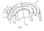
- the magnetic separation of the soft-magnetic annular regions are formed as a series of arcuate slots 20, so-called kidney slots, wherein between two slots 20 of the same radius each have a web-like connection 21 which mechanically connects two soft-magnetic annular regions. Therefore, in this radial region on the engaging clutch disc, the material thickness of the soft magnetic rings is limited by flat end faces. The flat end faces also avoid increased magnetic leakage flux through the slots 20.
Landscapes
- Engineering & Computer Science (AREA)
- General Engineering & Computer Science (AREA)
- Physics & Mathematics (AREA)
- Electromagnetism (AREA)
- Mechanical Engineering (AREA)
- Braking Arrangements (AREA)
- Mechanical Operated Clutches (AREA)
Description
Die Erfindung betrifft eine elektromagnetische Reibungskupplung nach dem Oberbegriff des Anspruchs 1.The invention relates to an electromagnetic friction clutch according to the preamble of
Es sind verschiedene elektromagnetische Reibungskupplungen bekannt, deren Kupplungsscheiben eine unebene Reibfläche aufweisen. Es sind elektromagnetische Kupplungen bekannt, deren Ankerscheiben vom magnetischen Fluss mehrfach durchflutet werden. Deren Polflächen sind eben ausgebildet. Durch die Mehrfachdurchflutung wird eine Erhöhung des Reibmoments erzielt.Various electromagnetic friction clutches are known whose clutch discs have an uneven friction surface. There are known electromagnetic couplings whose armature disks are repeatedly flooded by the magnetic flux. Their pole faces are flat. Due to the multiple flooding, an increase in the friction torque is achieved.
Eine gattungsgemäße Reibkupplung ist aus
Der Erfindung liegt die Aufgabe zugrunde, eine Kupplung bereitzustellen, die ein vergleichweise vergrößertes maximales Drehmoment bei raumsparender Bauweise überträgt.The invention has for its object to provide a coupling which transmits a comparatively increased maximum torque in a space-saving design.
Diese Aufgabe wird durch die Merkmale des Anspruchs 1 gelöst. In den abhängigen Ansprüchen sind vorteilhafte und zweckmäßige Weiterbildungen der Erfindung angegeben.This object is solved by the features of
Die Erfindung geht von einer elektromagnetischen Reibungskupplung mit zwei Kupplungsscheiben aus, wobei eine Kupplungsscheibe eine axial bewegliche Ankerscheibe umfasst. Die Kupplungsscheiben weisen mehrere konzentrisch kreisförmige weichmagnetische Ringbereiche auf, die voneinander zumindest teilweise magnetisch isoliert sind. Die axial bewegliche Ankerscheibe weist mindestens einen magnetisch leitenden Ringbereich auf, der zwei magnetisch isolierte Ringbereiche der zweien Kupplungsscheibe magnetisch verbindet. Der Kern der Erfindung besteht nun darin, dass die Kupplungsscheiben im radialen Querschnitt betrachtet, oszillierende Polflächen an den weichmagnetischen Ringbereichen aufweisen, welche zumindest teilweise als Reibflächen ausgebildet sind, und über welche eine Anziehung bei einem Schalten der Kupplung stattfindet, wobei das radiale Querschnittsprofil beider Kupplungsschreiben zumindest im Bereich von Reibflächen passgenau aufeinander abgestimmt ist.The invention is based on an electromagnetic friction clutch with two clutch plates, wherein a Clutch disc comprises an axially movable armature disc. The clutch discs have a plurality of concentric circular soft-magnetic ring areas, which are at least partially magnetically isolated from each other. The axially movable armature disk has at least one magnetically conductive annular region which magnetically connects two magnetically isolated annular regions of the two clutch disk. The essence of the invention consists in the fact that the clutch discs viewed in radial cross-section, having oscillating pole faces on the soft magnetic annular regions, which are at least partially formed as friction surfaces, and via which an attraction takes place in a switching of the clutch, wherein the radial cross-sectional profile of both coupling letters at least in the area of friction surfaces is precisely matched to each other.
Im Folgenden wird die Seite einer Kupplungsscheibe, die zur jeweils gegenüberliegenden Kupplungsscheibe gewandt ist, als Arbeitsseite bezeichnet. Das Oszillieren der Polflächen ist so zu verstehen, dass die Kupplungsscheiben an der Oberfläche ihrer jeweiligen Arbeitsseite im Querschnitt ein Profil aufweisen, das mit wachsendem Radius abwechselnd in axialer Richtung steigende und fallende Bereiche aufweist. Dies bewirkt, daß die Oberflächen der Kupplungsscheiben an ihrer Arbeitsseite konzentrische Erhebungen bzw. Vertiefungen zeigen. Um die Drehachse umlaufend ist das Oberflächenprofil der Kupplungsscheiben vorzugsweise überwiegend gleichmäßig glatt, insbesondere in Bereichen in denen sich die Kupplungsscheiben im eingekuppelten Zustand berühren. Die Drehsymmetrie der Kupplungsscheiben auf der Arbeitsseite kann in Bereichen gestört sein, die insbesondere gegenüber den Reibflächen axial zurückgesetzt sind.Hereinafter, the side of a clutch disc, which is turned to the respective opposite clutch disc, referred to as the working side. The oscillation of the pole faces is to be understood such that the coupling disks have on the surface of their respective working side in cross-section a profile which alternately has increasing and decreasing areas in the axial direction with increasing radius. This causes the surfaces of the clutch discs on their working side show concentric elevations or depressions. The surface profile of the clutch disks is preferably predominantly uniformly smooth around the axis of rotation, in particular in areas in which the clutch disks contact each other in the engaged state. The rotational symmetry of the clutch discs on the working side can be disturbed in areas which are axially reset in particular with respect to the friction surfaces.
Gegenüber ebenen Polflächen bietet der axial über den Radius oszillierende Verlauf den Vorteil, dass die Fläche, über die eine magnetische Anziehung stattfinden kann, vergößert ist. Insbesondere wenn die konzentrischen Erhebungen und Vertiefungen der beiden Kupplungsscheiben so zueinander versetzt sind, dass sie zumindest teilweise ineinander hineinreichen und die Oberflächen ihrer Arbeitsseiten im eingekuppelten Zustand ineinandergreifen, bieten die oszillierenden Polflächen den Vorteil, dass der Kraftschluss gegenüber Stößen und Schwingungen senkrecht zur Drehachse unempfindlicher wird.Opposite planar pole faces of the axially oscillating over the radius profile has the advantage that the area over which a magnetic attraction can take place is increased. Especially if the concentric surveys and Recesses of the two clutch plates are offset from each other so that they at least partially extend into each other and engage the surfaces of their working sides in the engaged state, the oscillating pole faces offer the advantage that the adhesion to shocks and vibrations perpendicular to the axis of rotation becomes less sensitive.
Besonders zweckmäßig ist eine Ausführung der Erfindung, bei der die weichmagnetischen Ringbereiche einer Kupplungsscheibe zwischen magnetischen Isoliermitteln eines Ringbereichs einer Kupplungsscheibe im Querschnittsverlauf ein Maximum in axialer Richtung aufweisen. Hierbei erhalten die weichmagnetischen Ringbereiche vorteilhafterweise ein axiales Querschnittsprofil, das mit zunehmendem Radius eine steigende und eine fallende Flanke in axialer Richtung aufweist und zwischen diesen Flanken ein Maximum ausbildet. Somit können die magnetisch leitenden Bereiche für ein gegenseitiges Ineinandergreifen der Kupplungsscheiben vorbestimmt werden, wobei die Flanken zumindest teilweise als Polflächen wirken. Hieraus ergibt sich gegenüber ebenen Polflächen der Vorteil, dass der magnetische Fluß nicht mehr vollständig seine Richtung umkehren muß, um einen magnetisch leitenden Bereich zu durchfluten, so daß vorteilhaft magnetische Streuverluste verringert und der Wirkungsgrad der magnetischen Krafterzeugung verbessert werden können. Dabei bietet sich zudem die Möglichkeit, den magnetischen Fluß über einen vergleichweise kürzeren Pfad durch die ineinander greifenden, weichmagnetischen Ringbereiche im eingekuppelten Zustand zu leiten, so daß die Wirkung von Bereichen mit unerwünschten magnetischen Kurzschlüssen gemieden werden kann.Particularly useful is an embodiment of the invention, in which the soft magnetic annular regions of a clutch disc between magnetic insulating means of a ring portion of a clutch disc in the cross-sectional profile have a maximum in the axial direction. In this case, the soft-magnetic annular regions advantageously receive an axial cross-sectional profile which, with increasing radius, has a rising and a falling flank in the axial direction and forms a maximum between these flanks. Thus, the magnetically conductive regions can be predetermined for a mutual engagement of the clutch discs, wherein the flanks act at least partially as pole faces. This results in the advantage over flat pole faces that the magnetic flux does not have to completely reverse its direction in order to penetrate a magnetically conductive region, so that advantageous magnetic leakage losses can be reduced and the efficiency of magnetic force generation can be improved. It also offers the possibility to conduct the magnetic flux over a comparatively shorter path through the interlocking, soft magnetic ring areas in the engaged state, so that the effect of areas with unwanted magnetic short circuits can be avoided.
Erfindungsgemäß bilden die Polflächen zumindest teilweise Reibflächen. Weil an den Polflächen die stärksten Anziehungskräfte herrschen, bieten die magnetischen Polflächen die besten Bedingungen für eine Drehmomentübertragung durch Reibkontakt.According to the invention, the pole faces at least partially form friction surfaces. Because of the strongest attraction on the pole faces, the magnetic pole faces provide the best conditions for torque transmission through frictional contact.
Des Weiteren ist erfindungsgemäß das radiale Querschnittsprofil beider Kupplungsscheiben passgenau aufeinander abgestimmt. Dies bietet zum Einen den Vorteil, dass die magnetischen Polflächen bei getrennter Lage der beiden Kupplungsscheiben in einem kleinen Abstand gehalten werden können. Beim Einschalten, beispielsweise des Elektromagneten, wirken daher starke Kräfte und ermöglichen ein schnelles Zuschalten der Kupplung. Weiterhin bewirkt die passgenaue Ausführung der Kupplungsflächen, dass der zur Verfügung stehende Flächeninhalt optimal für den Reibungskraftschluss genutzt werden kann.Furthermore, according to the invention, the radial cross-sectional profile of the two clutch discs is matched precisely to one another. This offers on the one hand the advantage that the magnetic pole faces in a separate position the two clutch plates can be kept at a small distance. When switching on, for example, the electromagnet, therefore strong forces and enable a quick connection of the clutch. Furthermore, the tailor-made design of the coupling surfaces, that the available surface area can be optimally used for the Reibungskraftschluss.
In einer besonders bevorzugten Ausführung weisen die weichmagnetischen Ringbereiche konische Polflächen auf. Dies bietet den Vorteil, dass die Polflächen besonders einfach und genau hergestellt werden können.In a particularly preferred embodiment, the soft-magnetic ring areas have conical pole faces. This offers the advantage that the pole faces can be made particularly simple and accurate.
Im radialen Querschnittsprofil der Arbeitsseite einer Kupplungsscheibe erscheinen die konischen Polflächen vorzugsweise als in axialer Richtung zur gegenüberliegenden Kupplungsscheibe hin linear ansteigende bzw. abfallende Flanken. Dadurch lässt sich ihre Dimensionierung einfacher berechnen.In the radial cross-sectional profile of the working side of a clutch disc, the conical pole faces preferably appear as flanks rising or falling in the axial direction in relation to the opposite clutch disc. This makes it easier to calculate their sizing.
Eine weitere bevorzugte Ausbildung der Erfindung zeichnet sich dadurch aus, dass die weichmagnetischen Ringbereiche einer Kupplungsscheibe umfänglich durch Spalte voneinander getrennt und dass die Ringbereiche durch Stege in radialer Richtung mechanisch fest miteinander verbunden sind. Die magnetische Isolation der weichmagnetischen Ringbereiche wird z.B. hierbei im Wesentlichen durch Materialabtragung, beispielsweise ausfräsen, hergestellt. Dabei kann Material, das zur festen mechanischen Verbindung der weichmagnetischen Ringbereiche untereinander vorgesehen ist, von der Materialabtragung ausgenommen werden. Die Strukturen dieser Kupplungsscheiben können so dimensioniert sein, dass nur noch wenige oder gar keine weiteren Bearbeitungsschritte zu ihrer Herstellung nötig sind. Zugleich werden Gewicht und Trägheitsmoment der Kupplungsscheiben vorteilhaft verringert, wodurch sich ihr Schaltverhalten verbessert.A further preferred embodiment of the invention is characterized in that the soft-magnetic ring areas of a clutch disc are circumferentially separated from one another by gaps and that the ring areas are mechanically fixed to one another by webs in the radial direction. The magnetic isolation of the soft magnetic annular regions is e.g. in this case essentially by material removal, for example, cut, produced. In this case, material which is provided for the fixed mechanical connection of the soft-magnetic annular areas with one another can be excluded from the material removal. The structures of these clutch discs can be dimensioned so that only a few or no further processing steps are necessary for their production. At the same time weight and moment of inertia of the clutch plates are advantageously reduced, thereby improving their switching behavior.
Es erweist sich als günstig, dass die axial tiefere Berandung einer Pol- und/oder Reibfläche eines weichmagnetischen Ringbereichs einer Kupplungsscheibe an den Rand eines magnetisch isolierenden Bereichs in der Kupplungsscheibe stößt. Folglich liegen die isolierenden Bereiche einer Kupplungsscheibe in den Vertiefungen ihrer Arbeitsseite. Weil der magnetische Fluss im Wesentlichen durch die Polflächen an den ansteigenden und abfallenden Flanken der weichmagnetischen Bereiche durchgeleitet wird, bietet diese Anordnung der isolierenden Bereiche den Vorteil, dass der magnetische Fluss an den isolierenden Bereichen vorbeigeleitet wird und somit nur ein geringer Verlust durch Streufluss über die isolierenden Bereiche entstehen kann. Es ist zweckmäßig, dass die axial äußerste Erhebung eines weichmagnetischen Ringbereichs einer Kupplungsscheibe nur bis zur axial tiefsten Berandung einer Polfläche und/oder Reibfläche der gegenüberliegenden Kupplungsscheibe reicht, wenn die Kupplungsscheiben miteinander in Reibkontakt stehen. In angezogener Stellung greifen die Kupplungsscheiben vorzugsweise so ineinander, dass sie in axialer Richtung einen mittleren Bereich bilden, den der magnetische Fluss mit vergleichsweise geringen Richtungsänderungen durchfluten kann. Vorzugsweise kann die axiale Reichweite der weichmagnetischen Bereiche in die gegenüberliegende Kupplungsscheibe hierbei derart limitiert werden, dass an den isolierenden Bereichen kein oder kaum Streufluss entstehen kann, der die magnetische Anziehung an den Polflächen verringert. Somit verbessert auch diese Maßnahme den Wirkungsgrad der Kupplung.It proves to be advantageous that the axially lower edge of a pole and / or friction surface of a soft-magnetic annular region of a clutch disc abuts the edge of a magnetically insulating region in the clutch disc. Consequently, the insulating regions are one Clutch disc in the recesses of their working side. Because the magnetic flux is transmitted substantially through the pole faces at the rising and falling edges of the soft magnetic regions, this arrangement of the insulating regions offers the advantage that the magnetic flux is conducted past the insulating regions and thus only a small leakage by leakage flux over the insulating areas can arise. It is expedient that the axially outermost elevation of a soft-magnetic annular region of a clutch disk only extends to the axially lowest edge of a pole surface and / or friction surface of the opposite clutch disk when the clutch disks are in frictional contact with one another. In the tightened position, the clutch discs preferably engage with each other so that they form a central region in the axial direction, which can flow through the magnetic flux with relatively small changes in direction. Preferably, the axial range of the soft magnetic regions in the opposite clutch disc can be limited in this case such that no or hardly any leakage flux can arise at the insulating regions, which reduces the magnetic attraction at the pole faces. Thus, this measure also improves the efficiency of the clutch.
Eine weitere zweckmäßige Ausführung der Erfindung sieht vor, dass zwischen weichmagnetischen Ringbereichen einer Kupplungsscheibe festes magnetisch isolierendes Material eingebracht ist und in dem magnetisch isolierenden Bereich zumindest teilweise eine Reibfläche ausgebildet ist. Auf diese Weise kann die Reibfläche weiter vergrößert werden und damit das übertragbare Moment vorteilhaft erhöht werden.A further expedient embodiment of the invention provides that between magnetically soft annular regions of a clutch disc fixed magnetically insulating material is introduced and in the magnetically insulating region at least partially a friction surface is formed. In this way, the friction surface can be further increased and thus the transmittable torque can be advantageously increased.
Zeichnungen:
- Figur 1a
- Schematische Darstellung einer halben elektromagnetischen Reibungskupplung im entkuppelten Zustand in der Ansicht der Schnittebene entlang der Drehachse S und einer radialen Richtung,
- Figur 1b
- wie
Figur 1a , jedoch im eingekuppelten Zustand, Figur 2- perspektivische Schnittansicht der halbierten Kupplungsscheiben im Reibkontakt mit Ansicht des Querschnitts entlang der Drehachse S.
- FIG. 1a
- Schematic representation of a half electromagnetic friction clutch in the decoupled state in the view of Cutting plane along the rotation axis S and a radial direction,
- FIG. 1b
- as
FIG. 1a but in the engaged state, - FIG. 2
- Perspective sectional view of the halved clutch discs in frictional contact with view of the cross section along the axis of rotation S.
Die
Die Ankerscheibe 2 besteht aus drei weichmagnetischen Ringbereichen 3a, 3b, 3c, die durch die Schlitze 7a und 7b magnetisch voneinander getrennt werden. Der Rotor 8 weist vier konzentrische weichmagnetische Ringbereiche 9a, 9b, 9c und 9d auf. Der äußerste Ringbereich 9a sowie der innerste Ringbereich 9d sind in axialer Richtung weiter ausgedehnt, so dass sie den elektrischen Ringmagneten 14 in einem U-förmigen Profil teilweise umfassen. Die weichmagnetischen Ringbereiche des Rotors 9a, 9b, 9c, 9d werden ebenfalls von Schlitzen 13a, 13b und 13c magnetisch voneinander isoliert.The
Im entkuppelten Zustand sind die Spulenwindungen 15 des Elektromagneten 14 stromlos, sodass die Ankerscheibe 2 in einer beabstandeten Position gehalten wird. Um die Kupplung 1 einzukuppeln, wie in
Die lineare Zunahme und Abnahme der axialen Materialstärke der weichmagnetischen Ringbereiche 3a - 3c, 9a - 9d an beiden Kupplungsscheiben 2, 8 lässt erkennen, dass die Polflächen 4a - 4f, 10a - 10f konisch ausgebildet sind. Alle Polflächen 4a - 4f, 10a - 10f sind in einem Winkel zur Drehachse S angestellt. Dargestellt ist ein Winkel von etwa 45°. Vorzugsweise werden die Polflächen in Winkeln von weniger als 60° zur Drehachse angestellt, wobei sich Winkel von 45° und kleiner als geeigneter erwiesen haben. Besonders bevorzugt werden Anstellwinkel von 30° und weniger, beispielsweise 27°. Die steiler angestellten Pol- und Reibflächen greifen dabei wie Keile ineinander, wodurch das übertragbare Drehmoment der Kupplung weiter erhöht wird. Um ein Verklemmen der Kupplungsscheiben möglichst zu vermeiden, werden vorzugweise Anstellwinkel von 20° und größer verwendet.The linear increase and decrease in the axial material thickness of the soft-magnetic
Jeder weichmagnetische Ringbereich, beispielsweise 3b, der Ankerscheibe 2 wird auf der Arbeitsseite von zwei konischen Flächen, z.B. 4c und 4d, begrenzt, von denen eine der Drehachse S zugewandt und die andere der Drehachse S abgewandt ist. So bilden die Polflächen 4a - 4f an der Arbeitsseite der Ankerscheibe im Querschnitt eine oszillierende Kontur, die mit zunehmenden Radius abwechselnd auf die gegenüberliegende Rotorscheibe zuläuft bzw. sich von ihr wieder entfernt.Each soft-magnetic annular region, for example 3b, of the
Die weichmagnetischen Ringbereiche 9a, 9b, 9c, 9d des Rotors 8 werden in ähnlicher Weise von Polflächen begrenzt, die passgenau zu den Polflächen der Ankerscheibe abwechselnd zur Drehachse S hin- bzw. abweisend angestellt sind. Die Ringelemente 9a und 9d haben jeweils nur eine Polfläche, da sie mit ihrer axialen Verlängerung den vom Elektromagneten 14 erzeugten magnetischen Fluß bündeln und an die Arbeitsseiten der Kupplungsscheiben 2,8 führen.The soft-magnetic
Die weichmagnetischen Ringbereiche 3a - 3c, 9a - 9d des Rotors 8 und der Ankerscheibe 2 sind zueinander so versetzt, dass die beiden Kupplungsscheiben 2,8 bereits im getrennten Zustand ineinander hineinreichen. Dabei stehen sich paarweise jeweils eine Polfläche des Rotors 8, z.B. 10d, und eine Polfläche der Ankerscheibe 2, z.B. 4d, gegenüber. Der innere z.B. kreisförmig umlaufende Rand 6a der Polfläche 4d stößt an den magnetisch trennenden Bereich 7b, der eine Vertiefung in der Ankerscheibe 2 bildet. An ihrem äußeren z.B. kreisförmig umlaufenden Rand 6b grenzt die Polfläche 4d der Ankerscheibe 2 an die Stirnfläche 5b, die die axiale Erhebung des weichmagnetischen Ringbereichs 3b in Richtung des Rotors beschränkt. In entsprechender Weise wird die Polfläche 10d des Rotors 8 an ihrem äußeren Rand 12a von der Vertiefung des magnetisch isolierenden Bereichs 13b und an ihrem inneren Rand 12b von der Stirnfläche 11b des weichmagnetischen Ringbereichs 9c an der axial äußersten Erhebung zur Ankerscheibe 2 hin begrenzt. Die
Die Bereiche größter Materialstärke der weichmagnetischen Ringe 3a - 3c, 9a - 9d reichen dabei jeweils in die Vertiefung der gegenüberliegenden Kupplungsscheibe, an denen sich die magnetisch isolierenden Schlitze 7a, 7b, 13a, 13b, 13c befinden. Dabei befinden sich an den Bereichen maximaler Materialstärke der Ankerscheibe 2 Stirnflächen 5a, 5b und 5c, die an den oberen Rand der Polflächen 4a, 4b, 4c, 4d, 4e und 4f angrenzen. Sie überdecken den radialen Bereich der Schlitze 13a, 13b und 13c der Rotorscheibe. Gleichermaßen werden die Schlitze der Ankerscheibe 7a, 7b von den Stirnflächen des Rotors 11a, 11b deckungsgleich überlagert.The areas of maximum material thickness of the soft
Beim Einschalten der Stromversorgung des Elektromagneten 15 findet der magnetische Fluss einen günstigen Weg über die Polflächen 4a - 4f, 10a - 10f des Rotors 8 und der Ankerscheibe 2, auf dem er zwischen den weichmagnetischen Bereichen 3a - 3c, 9a - 9d der beiden Kupplungsscheiben hin-und herwechseln kann. Durch die so erzeugte magnetische Anziehungskraft wird die Kupplung 1 in den Zustand der
In der
- 11
- Kupplungclutch
- 22
- Ankerscheibearmature disc
- 3a3a
- Ringbereich der AnkerscheibeRing area of the armature disk
- 3b3b
- Ringbereich der AnkerscheibeRing area of the armature disk
- 3c3c
- Ringbereich der AnkerscheibeRing area of the armature disk
- 4a4a
- Pol- und ReibflächePol and friction surface
- 4b4b
- Pol- und ReibflächePol and friction surface
- 4c4c
- Pol- und ReibflächePol and friction surface
- 4d4d
- Pol- und ReibflächePol and friction surface
- 4e4e
- Pol- und ReibflächePol and friction surface
- 4f4f
- Pol- und ReibflächePol and friction surface
- 5a5a
- Stirnflächeface
- 5b5b
- Stirnflächeface
- 5c5c
- Stirnflächeface
- 6a6a
- Tiefer RandDeep edge
- 6b6b
- Höherer RandHigher margin
- 7a7a
- Schlitzslot
- 7b7b
- Schlitzslot
- 88th
- Rotorrotor
- 9a9a
- Ringbereichring area
- 9b9b
- Ringbereichring area
- 9c9c
- Ringbereichring area
- 9d9d
- Ringbereichring area
- 10a10a
- Pol- und ReibflächePol and friction surface
- 10b10b
- Pol- und ReibflächePol and friction surface
- 10c10c
- Pol- und ReibflächePol and friction surface
- 10d10d
- Pol- und ReibflächePol and friction surface
- 10e10e
- Pol- und ReibflächePol and friction surface
- 10f10f
- Pol- und ReibflächePol and friction surface
- 11a11a
- Stirnflächeface
- 11b11b
- Stirnflächeface
- 12a12a
- Tieferer RandLower edge
- 12b12b
- Höherer RandHigher margin
- 13a13a
- Schlitzslot
- 13b13b
- Schlitzslot
- 13c13c
- Schlitzslot
- 1414
- Elektromagnetelectromagnet
- 1515
- Elektrische SpuleElectric coil
- 1616
- Kupplungsscheibenclutch discs
- 1717
- Ankerscheibearmature disc
- 1818
- Rotorrotor
- 1919
- Weichmagnetischer RingbereichSoft magnetic ring area
- 2020
- Schlitzslot
- 2121
- Stegweb
Claims (7)
- An electromagnetic friction clutch with two clutch disks (2, 8, 16), which have a plurality of concentric, circular, soft magnetic annular regions (3a-3c, 9a-9d, 19), which are at least partially magnetically isolated from one another, wherein one clutch disk includes an axially movable anchor disk (2,17) which has at least one magnetically conductive annular region (3a-3c, 19), which magnetically connects two magnetically isolated annular regions (9a-9d, 19) of the second clutch disk (8, 18), characterised in that the clutch disks (2, 8, 16) have oscillating pole surfaces (4a-4f, 10a-10f) on the soft magnetic annular regions (3a-3c, 9a-9d, 19), viewed in radial cross section, which are constructed, at least partially, in the form of friction surfaces (4a-4f, 10a-10f), and via which an attraction occurs on switching of the clutch, wherein the radial cross sectional profiles of the two clutch disks (2, 8,16) are accurately matched to one another, at least in the region of the friction surfaces (4a-4f, 10a-10f).
- An electromagnetic friction clutch as claimed in claim 1, characterised in that the clutch disk (2, 8, 16) each have a maximum in the axial direction in the radial cross sectional shape of the soft magnetic annular regions (3a-3c, 9a-9d, 19), which rises up towards the opposing clutch disk.
- An electromagnetic friction clutch as claimed in one of the preceding claims, characterised in that the soft magnetic annular regions (3a-3c, 9a-9d, 19) have conical pole faces (4a-4f, 10a-10f).
- An electromagnetic friction clutch as claimed in one of the preceding claims, characterised in that the soft magnetic annular regions (3a-3c, 9a-9d, 19) of one clutch disk (2, 8, 17, 18) are separated from one another circumferentially by gaps (7a, 7b, 13a-13c, 20) and that the annular regions (3a-3c, 9a-9d, 19) are mechanically rigidly connected together in the radial direction by webs (21).
- An electromagnetic friction clutch as claimed in one of the preceding claims, characterised in that the axially outermost raised portion of one soft magnetic annular region (3a-3c, 9a-9d, 19) of one clutch disk (2, 8, 17, 18) extends at most to the axially innermost edge of a pole face (4a-4f, 10a-10f) and/or friction surface in the recess of the opposite clutch disk, when the clutch disks (2, 8, 16) are in frictional contact with one another.
- An electromagnetic friction clutch as claimed in one of the preceding claims, characterised in that the axially deepest edge of one pole surface and/or friction surface (4a-4f, 10a-10f) of one soft magnetic annular region (3a-3c, 9a19c, 19) in one clutch disk (2, 8,17,18) presses against the edge of a magnetically isolating region (7a-7b, 13a-13c, 20) of the clutch disk.
- An electromagnetic friction clutch as claimed in one of the preceding claims, characterised in that inserted between soft magnetic annular regions (3a-3c, 9a-9d, 19) of one clutch disk (2, 8, 17, 18) there is solid, magnetically isolating material and formed in the magnetically isolating region (7a-7b, 13a-13c), at least partially, there is a friction surface.
Applications Claiming Priority (2)
| Application Number | Priority Date | Filing Date | Title |
|---|---|---|---|
| DE102009019139A DE102009019139A1 (en) | 2009-04-29 | 2009-04-29 | Electromagnetic friction clutch with oscillating pole faces |
| PCT/EP2010/000181 WO2010124749A1 (en) | 2009-04-29 | 2010-01-15 | Electromagnetic friction clutch having oscillating pole faces |
Publications (2)
| Publication Number | Publication Date |
|---|---|
| EP2425141A1 EP2425141A1 (en) | 2012-03-07 |
| EP2425141B1 true EP2425141B1 (en) | 2013-11-06 |
Family
ID=42060873
Family Applications (1)
| Application Number | Title | Priority Date | Filing Date |
|---|---|---|---|
| EP10700709.8A Not-in-force EP2425141B1 (en) | 2009-04-29 | 2010-01-15 | Electromagnetic friction clutch having oscillating pole faces |
Country Status (5)
| Country | Link |
|---|---|
| US (1) | US8839931B2 (en) |
| EP (1) | EP2425141B1 (en) |
| CN (1) | CN102422042A (en) |
| DE (1) | DE102009019139A1 (en) |
| WO (1) | WO2010124749A1 (en) |
Families Citing this family (5)
| Publication number | Priority date | Publication date | Assignee | Title |
|---|---|---|---|---|
| DE202011001197U1 (en) | 2010-10-14 | 2012-01-17 | Eto Magnetic Gmbh | Magnetically optimized friction clutch |
| JP2014095402A (en) * | 2012-11-08 | 2014-05-22 | Denso Corp | Electromagnetic clutch, and device and method for controlling the same |
| WO2014074438A1 (en) * | 2012-11-12 | 2014-05-15 | Borgwarner Inc. | Solenoid assembly for friction clutch |
| DE102014109125B4 (en) * | 2014-06-30 | 2016-09-29 | Kendrion (Villingen) Gmbh | Electromagnetic friction clutch or pole friction brake |
| CN108644250A (en) * | 2018-07-27 | 2018-10-12 | 合肥研新离合器有限公司 | A kind of friction clutch economic benefits and social benefits extrusion structure |
Family Cites Families (15)
| Publication number | Priority date | Publication date | Assignee | Title |
|---|---|---|---|---|
| US566508A (en) * | 1896-08-25 | Friction-clutch | ||
| US1756907A (en) * | 1928-06-09 | 1930-04-29 | Goodwin Hall J | Electromagnetic clutch |
| US3214084A (en) * | 1961-03-27 | 1965-10-26 | Borg Warner | Electromagnetic friction device and compressor control for same |
| US3451516A (en) * | 1968-01-12 | 1969-06-24 | Rca Corp | Electromagnetic clutch having eccentrically mounted poles |
| DE2055678B1 (en) | 1970-11-12 | 1972-03-09 | Heinemann R | Brake or clutch |
| JPS60205026A (en) * | 1984-03-28 | 1985-10-16 | Ogura Clutch Co Ltd | Electromagnetic coupling device |
| JPS6249025A (en) * | 1985-08-27 | 1987-03-03 | Sanden Corp | Electromagnetic clutch |
| EP0216514B1 (en) | 1985-08-23 | 1990-11-14 | Sanden Corporation | Electromagnetic clutches |
| JPH0357526U (en) * | 1989-10-12 | 1991-06-03 | ||
| US5125255A (en) | 1991-06-27 | 1992-06-30 | Dana Corporation | Method of making an electromagnetic coupling disc |
| JP2001200861A (en) | 2000-01-14 | 2001-07-27 | Mitsubishi Heavy Ind Ltd | Electromagnetic clutch |
| DE202004009184U1 (en) | 2004-06-11 | 2004-10-07 | Linnig Antriebstechnik Gmbh | An electromagnetically operated friction clutch has a moveable armature welded to a disc spring of ferromagnetic material |
| DE102004042687B4 (en) * | 2004-09-01 | 2009-04-16 | Linnig Trucktec Gmbh | Electromagnetically actuated friction disc clutch and rotor for such a clutch |
| DE102005025546A1 (en) | 2005-06-01 | 2006-12-07 | Kern Gmbh | Clutch brake combination e.g. for tool, packaging and printing machines, has clutch magnet and retarding magnet which coaxially arranged to rotation axle |
| US20100025131A1 (en) * | 2006-04-03 | 2010-02-04 | Bluwav Systems, Llc | Electric propulsion system |
-
2009
- 2009-04-29 DE DE102009019139A patent/DE102009019139A1/en not_active Withdrawn
-
2010
- 2010-01-15 EP EP10700709.8A patent/EP2425141B1/en not_active Not-in-force
- 2010-01-15 CN CN2010800190491A patent/CN102422042A/en active Pending
- 2010-01-15 US US13/266,216 patent/US8839931B2/en not_active Expired - Fee Related
- 2010-01-15 WO PCT/EP2010/000181 patent/WO2010124749A1/en not_active Ceased
Also Published As
| Publication number | Publication date |
|---|---|
| US20120132494A1 (en) | 2012-05-31 |
| EP2425141A1 (en) | 2012-03-07 |
| CN102422042A (en) | 2012-04-18 |
| US8839931B2 (en) | 2014-09-23 |
| DE102009019139A1 (en) | 2010-11-04 |
| WO2010124749A1 (en) | 2010-11-04 |
Similar Documents
| Publication | Publication Date | Title |
|---|---|---|
| DE3704643C2 (en) | ||
| EP2150717B2 (en) | Magnetorheological torque transmission device, the use thereof, and magnetorheological torque transmission method | |
| DE69917228T2 (en) | PULLEY WITH ELECTROMAGNETIC CLUTCH | |
| EP1989460A1 (en) | Clutch housing with apertures for receiving a clutch disk | |
| DE2911874A1 (en) | ELECTROMAGNETIC COUPLING AND METHOD OF MANUFACTURING IT | |
| EP2855969A1 (en) | Balancing element and method for balancing a clutch | |
| EP2425141A1 (en) | Electromagnetic friction clutch having oscillating pole faces | |
| DE10106802B4 (en) | One-way clutch | |
| AT516124A1 (en) | friction plate | |
| WO2012150093A1 (en) | Torsional vibration damper | |
| EP2422103B1 (en) | Method for producing clutch and brake discs for electromagnetic clutches or electromagnetic brakes having at least one friction surface element | |
| DE102016223033A1 (en) | coupling device | |
| DE2932661A1 (en) | CLUTCH | |
| DE102018122194A1 (en) | Coupling device | |
| DE2538494B2 (en) | Electromagnetically actuated friction disc clutch or brake | |
| DE102019005799A1 (en) | Turntable | |
| DE102014109125B4 (en) | Electromagnetic friction clutch or pole friction brake | |
| EP1966519A2 (en) | Clutch mounted on the outer edge of a torque converter, and method for mounting a clutch in a torque converter | |
| DE69403161T2 (en) | One-way clutch integrating a retaining ring having paired symmetrical connecting parts | |
| DE102016215295A1 (en) | centrifugal pendulum | |
| DE102006007688B4 (en) | Electromagnetically operated switching unit | |
| DE1924458A1 (en) | Electromagnetic clutch | |
| WO2018068782A1 (en) | Clutch device | |
| EP3874174A1 (en) | Friction clutch | |
| DE102019127553A1 (en) | Dynamic damping device |
Legal Events
| Date | Code | Title | Description |
|---|---|---|---|
| PUAI | Public reference made under article 153(3) epc to a published international application that has entered the european phase |
Free format text: ORIGINAL CODE: 0009012 |
|
| 17P | Request for examination filed |
Effective date: 20110318 |
|
| AK | Designated contracting states |
Kind code of ref document: A1 Designated state(s): AT BE BG CH CY CZ DE DK EE ES FI FR GB GR HR HU IE IS IT LI LT LU LV MC MK MT NL NO PL PT RO SE SI SK SM TR |
|
| DAX | Request for extension of the european patent (deleted) | ||
| REG | Reference to a national code |
Ref country code: DE Ref legal event code: R079 Ref document number: 502010005272 Country of ref document: DE Free format text: PREVIOUS MAIN CLASS: F16D0027110000 Ipc: F16D0027112000 |
|
| RIC1 | Information provided on ipc code assigned before grant |
Ipc: F16D 27/112 20060101AFI20120913BHEP Ipc: F16D 27/11 20060101ALI20120913BHEP |
|
| 17Q | First examination report despatched |
Effective date: 20120924 |
|
| GRAP | Despatch of communication of intention to grant a patent |
Free format text: ORIGINAL CODE: EPIDOSNIGR1 |
|
| INTG | Intention to grant announced |
Effective date: 20130617 |
|
| GRAS | Grant fee paid |
Free format text: ORIGINAL CODE: EPIDOSNIGR3 |
|
| GRAA | (expected) grant |
Free format text: ORIGINAL CODE: 0009210 |
|
| AK | Designated contracting states |
Kind code of ref document: B1 Designated state(s): AT BE BG CH CY CZ DE DK EE ES FI FR GB GR HR HU IE IS IT LI LT LU LV MC MK MT NL NO PL PT RO SE SI SK SM TR |
|
| REG | Reference to a national code |
Ref country code: GB Ref legal event code: FG4D Free format text: NOT ENGLISH |
|
| REG | Reference to a national code |
Ref country code: CH Ref legal event code: EP |
|
| REG | Reference to a national code |
Ref country code: AT Ref legal event code: REF Ref document number: 639707 Country of ref document: AT Kind code of ref document: T Effective date: 20131215 |
|
| REG | Reference to a national code |
Ref country code: IE Ref legal event code: FG4D Free format text: LANGUAGE OF EP DOCUMENT: GERMAN |
|
| REG | Reference to a national code |
Ref country code: DE Ref legal event code: R096 Ref document number: 502010005272 Country of ref document: DE Effective date: 20140102 |
|
| REG | Reference to a national code |
Ref country code: NL Ref legal event code: VDEP Effective date: 20131106 |
|
| REG | Reference to a national code |
Ref country code: LT Ref legal event code: MG4D |
|
| PG25 | Lapsed in a contracting state [announced via postgrant information from national office to epo] |
Ref country code: SE Free format text: LAPSE BECAUSE OF FAILURE TO SUBMIT A TRANSLATION OF THE DESCRIPTION OR TO PAY THE FEE WITHIN THE PRESCRIBED TIME-LIMIT Effective date: 20131106 Ref country code: HR Free format text: LAPSE BECAUSE OF FAILURE TO SUBMIT A TRANSLATION OF THE DESCRIPTION OR TO PAY THE FEE WITHIN THE PRESCRIBED TIME-LIMIT Effective date: 20131106 Ref country code: LT Free format text: LAPSE BECAUSE OF FAILURE TO SUBMIT A TRANSLATION OF THE DESCRIPTION OR TO PAY THE FEE WITHIN THE PRESCRIBED TIME-LIMIT Effective date: 20131106 Ref country code: NL Free format text: LAPSE BECAUSE OF FAILURE TO SUBMIT A TRANSLATION OF THE DESCRIPTION OR TO PAY THE FEE WITHIN THE PRESCRIBED TIME-LIMIT Effective date: 20131106 Ref country code: NO Free format text: LAPSE BECAUSE OF FAILURE TO SUBMIT A TRANSLATION OF THE DESCRIPTION OR TO PAY THE FEE WITHIN THE PRESCRIBED TIME-LIMIT Effective date: 20140206 Ref country code: FI Free format text: LAPSE BECAUSE OF FAILURE TO SUBMIT A TRANSLATION OF THE DESCRIPTION OR TO PAY THE FEE WITHIN THE PRESCRIBED TIME-LIMIT Effective date: 20131106 Ref country code: IS Free format text: LAPSE BECAUSE OF FAILURE TO SUBMIT A TRANSLATION OF THE DESCRIPTION OR TO PAY THE FEE WITHIN THE PRESCRIBED TIME-LIMIT Effective date: 20140306 |
|
| PG25 | Lapsed in a contracting state [announced via postgrant information from national office to epo] |
Ref country code: ES Free format text: LAPSE BECAUSE OF FAILURE TO SUBMIT A TRANSLATION OF THE DESCRIPTION OR TO PAY THE FEE WITHIN THE PRESCRIBED TIME-LIMIT Effective date: 20131106 Ref country code: LV Free format text: LAPSE BECAUSE OF FAILURE TO SUBMIT A TRANSLATION OF THE DESCRIPTION OR TO PAY THE FEE WITHIN THE PRESCRIBED TIME-LIMIT Effective date: 20131106 |
|
| PG25 | Lapsed in a contracting state [announced via postgrant information from national office to epo] |
Ref country code: PT Free format text: LAPSE BECAUSE OF FAILURE TO SUBMIT A TRANSLATION OF THE DESCRIPTION OR TO PAY THE FEE WITHIN THE PRESCRIBED TIME-LIMIT Effective date: 20140306 |
|
| BERE | Be: lapsed |
Owner name: KENDRION LINNIG G.M.B.H. Effective date: 20140131 |
|
| PG25 | Lapsed in a contracting state [announced via postgrant information from national office to epo] |
Ref country code: EE Free format text: LAPSE BECAUSE OF FAILURE TO SUBMIT A TRANSLATION OF THE DESCRIPTION OR TO PAY THE FEE WITHIN THE PRESCRIBED TIME-LIMIT Effective date: 20131106 |
|
| REG | Reference to a national code |
Ref country code: DE Ref legal event code: R097 Ref document number: 502010005272 Country of ref document: DE |
|
| PG25 | Lapsed in a contracting state [announced via postgrant information from national office to epo] |
Ref country code: LU Free format text: LAPSE BECAUSE OF FAILURE TO SUBMIT A TRANSLATION OF THE DESCRIPTION OR TO PAY THE FEE WITHIN THE PRESCRIBED TIME-LIMIT Effective date: 20140115 Ref country code: CZ Free format text: LAPSE BECAUSE OF FAILURE TO SUBMIT A TRANSLATION OF THE DESCRIPTION OR TO PAY THE FEE WITHIN THE PRESCRIBED TIME-LIMIT Effective date: 20131106 Ref country code: IT Free format text: LAPSE BECAUSE OF FAILURE TO SUBMIT A TRANSLATION OF THE DESCRIPTION OR TO PAY THE FEE WITHIN THE PRESCRIBED TIME-LIMIT Effective date: 20131106 Ref country code: PL Free format text: LAPSE BECAUSE OF FAILURE TO SUBMIT A TRANSLATION OF THE DESCRIPTION OR TO PAY THE FEE WITHIN THE PRESCRIBED TIME-LIMIT Effective date: 20131106 Ref country code: RO Free format text: LAPSE BECAUSE OF FAILURE TO SUBMIT A TRANSLATION OF THE DESCRIPTION OR TO PAY THE FEE WITHIN THE PRESCRIBED TIME-LIMIT Effective date: 20131106 Ref country code: SK Free format text: LAPSE BECAUSE OF FAILURE TO SUBMIT A TRANSLATION OF THE DESCRIPTION OR TO PAY THE FEE WITHIN THE PRESCRIBED TIME-LIMIT Effective date: 20131106 |
|
| REG | Reference to a national code |
Ref country code: CH Ref legal event code: PL |
|
| PLBE | No opposition filed within time limit |
Free format text: ORIGINAL CODE: 0009261 |
|
| STAA | Information on the status of an ep patent application or granted ep patent |
Free format text: STATUS: NO OPPOSITION FILED WITHIN TIME LIMIT |
|
| PG25 | Lapsed in a contracting state [announced via postgrant information from national office to epo] |
Ref country code: DK Free format text: LAPSE BECAUSE OF FAILURE TO SUBMIT A TRANSLATION OF THE DESCRIPTION OR TO PAY THE FEE WITHIN THE PRESCRIBED TIME-LIMIT Effective date: 20131106 |
|
| 26N | No opposition filed |
Effective date: 20140807 |
|
| GBPC | Gb: european patent ceased through non-payment of renewal fee |
Effective date: 20140206 |
|
| PG25 | Lapsed in a contracting state [announced via postgrant information from national office to epo] |
Ref country code: CH Free format text: LAPSE BECAUSE OF NON-PAYMENT OF DUE FEES Effective date: 20140131 Ref country code: LI Free format text: LAPSE BECAUSE OF NON-PAYMENT OF DUE FEES Effective date: 20140131 |
|
| REG | Reference to a national code |
Ref country code: FR Ref legal event code: ST Effective date: 20140930 |
|
| REG | Reference to a national code |
Ref country code: IE Ref legal event code: MM4A |
|
| REG | Reference to a national code |
Ref country code: DE Ref legal event code: R097 Ref document number: 502010005272 Country of ref document: DE Effective date: 20140807 |
|
| PG25 | Lapsed in a contracting state [announced via postgrant information from national office to epo] |
Ref country code: FR Free format text: LAPSE BECAUSE OF NON-PAYMENT OF DUE FEES Effective date: 20140131 |
|
| PG25 | Lapsed in a contracting state [announced via postgrant information from national office to epo] |
Ref country code: IE Free format text: LAPSE BECAUSE OF NON-PAYMENT OF DUE FEES Effective date: 20140115 Ref country code: GB Free format text: LAPSE BECAUSE OF NON-PAYMENT OF DUE FEES Effective date: 20140206 Ref country code: BE Free format text: LAPSE BECAUSE OF NON-PAYMENT OF DUE FEES Effective date: 20140131 |
|
| PG25 | Lapsed in a contracting state [announced via postgrant information from national office to epo] |
Ref country code: SI Free format text: LAPSE BECAUSE OF FAILURE TO SUBMIT A TRANSLATION OF THE DESCRIPTION OR TO PAY THE FEE WITHIN THE PRESCRIBED TIME-LIMIT Effective date: 20131106 |
|
| PG25 | Lapsed in a contracting state [announced via postgrant information from national office to epo] |
Ref country code: MC Free format text: LAPSE BECAUSE OF FAILURE TO SUBMIT A TRANSLATION OF THE DESCRIPTION OR TO PAY THE FEE WITHIN THE PRESCRIBED TIME-LIMIT Effective date: 20131106 |
|
| PG25 | Lapsed in a contracting state [announced via postgrant information from national office to epo] |
Ref country code: MT Free format text: LAPSE BECAUSE OF FAILURE TO SUBMIT A TRANSLATION OF THE DESCRIPTION OR TO PAY THE FEE WITHIN THE PRESCRIBED TIME-LIMIT Effective date: 20131106 |
|
| REG | Reference to a national code |
Ref country code: AT Ref legal event code: MM01 Ref document number: 639707 Country of ref document: AT Kind code of ref document: T Effective date: 20150115 |
|
| PG25 | Lapsed in a contracting state [announced via postgrant information from national office to epo] |
Ref country code: SM Free format text: LAPSE BECAUSE OF FAILURE TO SUBMIT A TRANSLATION OF THE DESCRIPTION OR TO PAY THE FEE WITHIN THE PRESCRIBED TIME-LIMIT Effective date: 20131106 |
|
| PGFP | Annual fee paid to national office [announced via postgrant information from national office to epo] |
Ref country code: TR Payment date: 20160107 Year of fee payment: 7 Ref country code: DE Payment date: 20160308 Year of fee payment: 7 |
|
| PG25 | Lapsed in a contracting state [announced via postgrant information from national office to epo] |
Ref country code: AT Free format text: LAPSE BECAUSE OF NON-PAYMENT OF DUE FEES Effective date: 20150115 |
|
| PG25 | Lapsed in a contracting state [announced via postgrant information from national office to epo] |
Ref country code: CY Free format text: LAPSE BECAUSE OF FAILURE TO SUBMIT A TRANSLATION OF THE DESCRIPTION OR TO PAY THE FEE WITHIN THE PRESCRIBED TIME-LIMIT Effective date: 20131106 Ref country code: BG Free format text: LAPSE BECAUSE OF FAILURE TO SUBMIT A TRANSLATION OF THE DESCRIPTION OR TO PAY THE FEE WITHIN THE PRESCRIBED TIME-LIMIT Effective date: 20131106 Ref country code: GR Free format text: LAPSE BECAUSE OF FAILURE TO SUBMIT A TRANSLATION OF THE DESCRIPTION OR TO PAY THE FEE WITHIN THE PRESCRIBED TIME-LIMIT Effective date: 20140207 |
|
| PG25 | Lapsed in a contracting state [announced via postgrant information from national office to epo] |
Ref country code: HU Free format text: LAPSE BECAUSE OF FAILURE TO SUBMIT A TRANSLATION OF THE DESCRIPTION OR TO PAY THE FEE WITHIN THE PRESCRIBED TIME-LIMIT; INVALID AB INITIO Effective date: 20100115 |
|
| REG | Reference to a national code |
Ref country code: DE Ref legal event code: R119 Ref document number: 502010005272 Country of ref document: DE |
|
| PG25 | Lapsed in a contracting state [announced via postgrant information from national office to epo] |
Ref country code: DE Free format text: LAPSE BECAUSE OF NON-PAYMENT OF DUE FEES Effective date: 20170801 |
|
| PG25 | Lapsed in a contracting state [announced via postgrant information from national office to epo] |
Ref country code: MK Free format text: LAPSE BECAUSE OF FAILURE TO SUBMIT A TRANSLATION OF THE DESCRIPTION OR TO PAY THE FEE WITHIN THE PRESCRIBED TIME-LIMIT Effective date: 20131106 |
|
| PG25 | Lapsed in a contracting state [announced via postgrant information from national office to epo] |
Ref country code: TR Free format text: LAPSE BECAUSE OF NON-PAYMENT OF DUE FEES Effective date: 20170115 |