EP2425135B1 - Kompressor und kupplungseinrichtung - Google Patents
Kompressor und kupplungseinrichtung Download PDFInfo
- Publication number
- EP2425135B1 EP2425135B1 EP10700306.3A EP10700306A EP2425135B1 EP 2425135 B1 EP2425135 B1 EP 2425135B1 EP 10700306 A EP10700306 A EP 10700306A EP 2425135 B1 EP2425135 B1 EP 2425135B1
- Authority
- EP
- European Patent Office
- Prior art keywords
- lubricant
- compressor
- crankshaft
- piston
- compressor according
- Prior art date
- Legal status (The legal status is an assumption and is not a legal conclusion. Google has not performed a legal analysis and makes no representation as to the accuracy of the status listed.)
- Active
Links
Images
Classifications
-
- F—MECHANICAL ENGINEERING; LIGHTING; HEATING; WEAPONS; BLASTING
- F04—POSITIVE - DISPLACEMENT MACHINES FOR LIQUIDS; PUMPS FOR LIQUIDS OR ELASTIC FLUIDS
- F04B—POSITIVE-DISPLACEMENT MACHINES FOR LIQUIDS; PUMPS
- F04B17/00—Pumps characterised by combination with, or adaptation to, specific driving engines or motors
- F04B17/05—Pumps characterised by combination with, or adaptation to, specific driving engines or motors driven by internal-combustion engines
-
- F—MECHANICAL ENGINEERING; LIGHTING; HEATING; WEAPONS; BLASTING
- F04—POSITIVE - DISPLACEMENT MACHINES FOR LIQUIDS; PUMPS FOR LIQUIDS OR ELASTIC FLUIDS
- F04B—POSITIVE-DISPLACEMENT MACHINES FOR LIQUIDS; PUMPS
- F04B35/00—Piston pumps specially adapted for elastic fluids and characterised by the driving means to their working members, or by combination with, or adaptation to, specific driving engines or motors, not otherwise provided for
- F04B35/002—Piston pumps specially adapted for elastic fluids and characterised by the driving means to their working members, or by combination with, or adaptation to, specific driving engines or motors, not otherwise provided for driven by internal combustion engines
-
- F—MECHANICAL ENGINEERING; LIGHTING; HEATING; WEAPONS; BLASTING
- F04—POSITIVE - DISPLACEMENT MACHINES FOR LIQUIDS; PUMPS FOR LIQUIDS OR ELASTIC FLUIDS
- F04B—POSITIVE-DISPLACEMENT MACHINES FOR LIQUIDS; PUMPS
- F04B39/00—Component parts, details, or accessories, of pumps or pumping systems specially adapted for elastic fluids, not otherwise provided for in, or of interest apart from, groups F04B25/00 - F04B37/00
- F04B39/02—Lubrication
-
- F—MECHANICAL ENGINEERING; LIGHTING; HEATING; WEAPONS; BLASTING
- F16—ENGINEERING ELEMENTS AND UNITS; GENERAL MEASURES FOR PRODUCING AND MAINTAINING EFFECTIVE FUNCTIONING OF MACHINES OR INSTALLATIONS; THERMAL INSULATION IN GENERAL
- F16C—SHAFTS; FLEXIBLE SHAFTS; ELEMENTS OR CRANKSHAFT MECHANISMS; ROTARY BODIES OTHER THAN GEARING ELEMENTS; BEARINGS
- F16C3/00—Shafts; Axles; Cranks; Eccentrics
- F16C3/04—Crankshafts, eccentric-shafts; Cranks, eccentrics
- F16C3/06—Crankshafts
- F16C3/14—Features relating to lubrication
-
- F—MECHANICAL ENGINEERING; LIGHTING; HEATING; WEAPONS; BLASTING
- F16—ENGINEERING ELEMENTS AND UNITS; GENERAL MEASURES FOR PRODUCING AND MAINTAINING EFFECTIVE FUNCTIONING OF MACHINES OR INSTALLATIONS; THERMAL INSULATION IN GENERAL
- F16C—SHAFTS; FLEXIBLE SHAFTS; ELEMENTS OR CRANKSHAFT MECHANISMS; ROTARY BODIES OTHER THAN GEARING ELEMENTS; BEARINGS
- F16C33/00—Parts of bearings; Special methods for making bearings or parts thereof
- F16C33/02—Parts of sliding-contact bearings
- F16C33/04—Brasses; Bushes; Linings
- F16C33/06—Sliding surface mainly made of metal
- F16C33/10—Construction relative to lubrication
- F16C33/1025—Construction relative to lubrication with liquid, e.g. oil, as lubricant
- F16C33/1045—Details of supply of the liquid to the bearing
- F16C33/1055—Details of supply of the liquid to the bearing from radial inside, e.g. via a passage through the shaft and/or inner sleeve
-
- F—MECHANICAL ENGINEERING; LIGHTING; HEATING; WEAPONS; BLASTING
- F01—MACHINES OR ENGINES IN GENERAL; ENGINE PLANTS IN GENERAL; STEAM ENGINES
- F01M—LUBRICATING OF MACHINES OR ENGINES IN GENERAL; LUBRICATING INTERNAL COMBUSTION ENGINES; CRANKCASE VENTILATING
- F01M1/00—Pressure lubrication
- F01M1/06—Lubricating systems characterised by the provision therein of crankshafts or connecting rods with lubricant passageways, e.g. bores
Definitions
- the invention relates to a compressor for generating compressed air in a vehicle according to the preamble of claim 1.
- the compressor can be separable from or connectable to a drive by means of a clutch device, for example a disconnect clutch.
- a generic compressor is for example from the DE 20 2006 019 190 U1 or the EP 0 238 336 A1 known.
- shut-off on compressors has the advantage that the compressor for energy saving by a drive, for example, the drive motor of the vehicle, can be separated when no compressed air generation is required. Without such a shut-off clutch, it was previously common to always run the compressor with the drive motor and in phases in which no compressed air generation was required to switch only pneumatically neutral. The introduction of a shut-off clutch for switching on and off of the compressor has the consequence that the compressor is subjected to a higher wear during connection than during continuous operation.
- the invention is therefore based on the object to improve the wear resistance of the compressor.
- the invention has the advantage of the wear resistance of the compressor and thus the durability even when using a coupling device significantly improve.
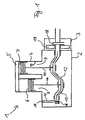
- the FIG. 1 shows a compressor 1 with a compressor housing 2 and arranged on the compressor housing 2 coupling device 3.
- the coupling device 3 is designed as a pneumatically actuated shut-off clutch.
- the coupling device 3 a pneumatic actuating cylinder 19, via the coupling means 18 at pneumatic loading, z.
- clutch plates or clutch plates are pressed against each other or separable from each other.
- the coupling device 3 connects a crankshaft 12 of the compressor 1 with a drive shaft of a drive device of a vehicle, not shown in detail, of a vehicle, for example the vehicle engine.
- the compressor 1 has a first cylinder 8 and a second cylinder 9.
- a first piston 6 is arranged in the first cylinder 8 .
- a second piston 7 is arranged in the second cylinder 9.
- the first piston 6 is connected to the crankshaft 12 via a first connecting rod 10 and corresponding bearings.
- the second piston 7 is also via a second connecting rod 11 via corresponding Bearing connected to the crankshaft 12.
- the storage of the piston 6, 7 and the crankshaft 12 in the corresponding bearing eyes of the connecting rods 10, 11 is in the FIG. 1 for the sake of simplicity only shown schematically. In practice, suitable sliding or roller bearings are used for this purpose.
- the cylinders 8, 9 are arranged in a cylinder housing 4 of the compressor 1.
- the cylinder housing 4 is part of the housing 2.
- valve and control block 5 On the cylinder housing 4, a valve and control block 5 is arranged, which includes, for example, the inlet and outlet valves for the compressed air intake and for the compressed air delivery to downstream units such as compressed air reservoir.
- the valve block 5 can be described in detail, for example, according to DE 197 451 18 A1 be educated.
- the compressor 1 has a lubricant supply.
- a lubricant for example, oil is used, for example, the engine oil of the vehicle engine.
- the lubricant supply of the compressor 1 has a lubricant connection 14 which is to be connected to the engine oil supply of the vehicle engine. From the lubricant port 14, a first lubricant passage 15 leads through the housing 2 to a lubricant supply groove 16 revolving around the crankshaft 12.
- the lubricant supply groove 16 is connected to a lubricant supply passage section 13 which extends in the form of a hollow passage within the crankshaft 12.
- the channel section 13 communicates with outlet points for the lubricant in the region of the connecting rods 10, 11, which are described below with reference to FIGS FIG. 2 will be explained in detail.
- the use of the circulating lubricant supply groove 16 has the advantage that the lubricant can be distributed on the circumference of the crankshaft 12 and, as a result, can be fed into the lubricant passage section 13 relatively quickly and uniformly.
- the lubricant is usually pressurized and is under a pressure of about 3 to 4 bar. As a result, a lubricant supply is independent of the movement of the compressor possible, ie even when stationary Compressor.
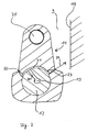
- FIG. 2 shows the connecting rod 11 in a sectional view.
- the connecting rod 11 has a connecting rod 25 which is connected to the cylinder 7.
- Another (lower) connecting rod eye comprises the crankshaft 12, which in the FIG. 2 also shown in section.
- a bearing for example a ball bearing, provided in the FIG. 2 is not explicitly shown to simplify the presentation.
- the passage portion 13 is connected to a radial lubricant portion 20 in the crankshaft 12, which serves to introduce the lubricant into the connecting rod 11.
- the connecting rod 11 has, in the region of the connecting rod receiving the crankshaft 12, a segment-like widened portion 21, which forms a channel between the crankshaft and the connecting rod inner side.
- the extended portion 21 may advantageously be designed as a recess within the connecting rod.
- the section 21 can also be designed as a groove in the crankshaft 12. It is crucial that a channel for forwarding the lubricant from the channel portion 13 to lubricant outlet 22, 23, is formed.
- the groove 21 passes the lubricant further to the lubricant outlet 22, 23, which are provided on both sides of the connecting rod 11. Also conceivable is an embodiment with only one lubricant outlet 22 or 23, but an increased lubricant throughput can be achieved through a plurality of lubricant outlets.
- the lubricant outlets 22, 23 are tapered in the direction of the lubricant outlet opening and thus designed in the manner of a nozzle. Due to the overpressure of the lubricant and the nozzle action of the lubricant outlets 22, 23, the lubricant is splashed out of the openings and hits, as in the FIG. 2 indicated by the arrow 24, on the cylinder wall 19. This ensures an early and good lubrication of the cylinder wall relative to the cylinder, even with temporarily switched off via the coupling device 3 compressor. 1
- the taper of the lubricant outlets 22, 23 may be continuous or stepped, with a linear or curved contour.
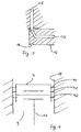
- FIG. 3 shows the inlet side connection of the crankshaft 12 to the lubricant port 14.
- the lubricant passage portion 13 is in communication with the circumferential groove 16 of the crankshaft 12.
- a connection to the lubricant channel 15 is ensured at each rotational angular position of the crankshaft, so that a secure and high throughput of lubricant through the channels 15, 13 is ensured.
- the lubricant supply channel 13, 15, 16, 20, 21 additionally on a lubricant supply gallery with a plurality of fixedly arranged in the crankcase of the compressor 1 lubricant nozzles.
- the lubricant nozzles are designed for molding the cylinder bore with the lubricant.
- the lubricant nozzles can be aligned with your outlet point on the cylinder bore or the cylinder wall 19. As a result, the lubrication of the compressor can be further improved.
- the FIG. 4 Sectionally shows the cylinder 9 with the piston 7.
- the piston 7, and possibly also the piston 6, are provided with arranged in circumferential grooves of the piston piston rings 40, 41, 42.
- the piston rings 40, 41 are formed as compression rings and provide an air seal of the above the piston 7 compression space relative to the lower crankcase. By using two compression rings increased density can be achieved compared to a compression ring.
- the piston ring 42 is formed as an oil scraper ring.
- the oil scraper ring should prevent the penetration of oil into the above the piston 7 compression space.
- the coating may advantageously contain chromium.
- the oil control ring 42 is formed chromed on its outer surface.
- the coupling device 3 projects over the housing 2 of the compressor 1 addition, that is, the coupling device is not, as from DE 20 2006 019 190 U1 known, integrated into the housing.
- the coupling device 3 protrudes at least with a coupling means 18, for example, the clutch disc or Lamellseil, containing area of the
Landscapes
- Engineering & Computer Science (AREA)
- General Engineering & Computer Science (AREA)
- Mechanical Engineering (AREA)
- Chemical & Material Sciences (AREA)
- Combustion & Propulsion (AREA)
- Ocean & Marine Engineering (AREA)
- Oil, Petroleum & Natural Gas (AREA)
- Compressor (AREA)
- Compressors, Vaccum Pumps And Other Relevant Systems (AREA)
Description
- Die Erfindung betrifft einen Kompressor für die Drucklufterzeugung in einem Fahrzeug gemäß dem Oberbegriff des Patenanspruchs 1. Der Kompressor kann über eine Kupplungseinrichtung, zum Beispiel eine Abschaltkupplung, von einem Antrieb trennbar oder damit verbindbar sein.
- Ein gattungsgemäßer Kompressor ist zum Beispiel aus der
DE 20 2006 019 190 U1 oder derEP 0 238 336 A1 bekannt. - Die Verwendung der bekannten Abschaltkupplung an Kompressoren hat den Vorteil, dass der Kompressor zur Energieeinsparung von einem Antrieb, zum Beispiel dem Antriebsmotor des Fahrzeuges, getrennt werden kann, wenn keine Drucklufterzeugung erforderlich ist. Ohne eine solche Abschaltkupplung war es bisher üblich, den Kompressor immer mit dem Antriebsmotor mitlaufen zu lassen und in Phasen, in denen keine Drucklufterzeugung erforderlich war, lediglich pneumatisch neutral zu schalten. Die Einführung einer Abschaltkupplung zum Zu- und Abschalten des Kompressors hat zur Folge, dass der Kompressor beim Zuschalten einem höheren Verschleiß unterworfen wird als beim ständigen Betrieb.
- Der Erfindung liegt daher die Aufgabe zugrunde, die Verschleißfestigkeit des Kompressors zu verbessern.
- Diese Aufgabe wird durch die in den unabhängigen Ansprüchen angegebene Erfindung gelöst. Die Unteransprüche enthalten vorteilhafte Ausgestaltungen der Erfindung.
- Die Erfindung hat den Vorteil, die Verschleißfestigkeit des Kompressors und damit die Dauerhaltbarkeit auch bei Verwendung einer Kupplungseinrichtung deutlich zu verbessern.
- Die Erfindung wird nachfolgend anhand von Ausführungsbeispielen unter Verwendung von Zeichnungen näher erläutert.
- Es zeigen:
- Figur 1
- einen Zweizylinder-Kompressor in schematischer Darstellung und
- Figur 2
- ein Spritzpleuel in Schnittdarstellung und
- Figur 3
- die einlassseitige Ausgestaltung der Schmiermittelversorgung und
- Figur 4
- Details eines Kolbens mit Kolbenringen.
- Die
Figur 1 zeigt einen Kompressor 1 mit einem Kompressorgehäuse 2 und eine an dem Kompressorgehäuse 2 angeordnete Kupplungseinrichtung 3. Die Kupplungseinrichtung 3 ist als pneumatisch betätigbare Abschaltkupplung ausgebildet. Hierfür weist die Kupplungseinrichtung 3 einen pneumatischen Betätigungszylinder 19 auf, über den bei pneumatischer Beaufschlagung Koppelmittel 18, z. B. Kupplungslamellen oder Kupplungsscheiben, aneinander pressbar oder voneinander trennbar sind. Die Kupplungseinrichtung 3 verbindet eine Kurbelwelle 12 des Kompressors 1 mit einer Antriebswelle einer nicht näher dargestellten Antriebseinrichtung eines Fahrzeuges, zum Beispiel dem Fahrzeugmotor. - Der Kompressor 1 weist einen ersten Zylinder 8 und einen zweiten Zylinder 9 auf. In dem ersten Zylinder 8 ist ein erster Kolben 6 angeordnet. In dem zweiten Zylinder 9 ist ein zweiter Kolben 7 angeordnet. Der erste Kolben 6 ist über ein erstes Pleuel 10 und entsprechende Lager mit der Kurbelwelle 12 verbunden. Der zweite Kolben 7 ist über ein zweites Pleuel 11 ebenfalls über entsprechende Lager mit der Kurbelwelle 12 verbunden. Die Lagerung der Kolben 6, 7 und der Kurbelwelle 12 in den entsprechenden Lageraugen der Pleuel 10, 11 ist in der
Figur 1 der Einfachheit halber nur schematisch dargestellt. In der Praxis werden hierfür geeignete Gleit- oder Wälzlager eingesetzt. Die Zylinder 8, 9 sind in einem Zylindergehäuse 4 des Kompressors 1 angeordnet. Das Zylindergehäuse 4 ist Teil des Gehäuses 2. - Auf dem Zylindergehäuse 4 ist ein Ventil- und Steuerblock 5 angeordnet, der beispielsweise die Einlass- und Auslassventile für die Druckluftansaugung und für die Druckluftabgabe an nachgeschaltete Einheiten wie z.B. Druckluftvorratsbehälter beinhaltet. Der Ventilblock 5 kann im Einzelnen beispielsweise gemäß der
DE 197 451 18 A1 ausgebildet sein. - Zur Schmierung der Kolben 6, 7 in den jeweiligen Zylindern 8, 9 weist der Kompressor 1 eine Schmiermittelversorgung auf. Als Schmiermittel wird beispielsweise Öl verwendet, zum Beispiel das Motoröl des Fahrzeugmotors. Die Schmiermittelversorgung des Kompressors 1 weist einen Schmiermittelanschluss 14 auf, der mit der Motoröl-Versorgung des Fahrzeugmotors zu verbinden ist. Von dem Schmiermittelanschluss 14 führt ein erster Schmiermittelkanal 15 durch das Gehäuse 2 zu einer um die Kurbelwelle 12 umlaufenden Schmiermittel-Versorgungsnut 16. Die Schmiermittel-Versorgungsnut 16 ist mit einem Schmiermittelversorgungs-Kanalabschnitt 13 verbunden, der in Form eines Hohlkanals innerhalb der Kurbelwelle 12 verläuft. Der Kanalabschnitt 13 steht mit Auslassstellen für das Schmiermittel im Bereich der Pleuel 10, 11 in Verbindung, die nachfolgend anhand der
Figur 2 im Detail näher erläutert werden. Die Verwendung der umlaufenden Schmiermittel-Versorgungsnut 16 hat den Vorteil, dass sich das Schmiermittel auf dem Umfang der Kurbelwelle 12 verteilen kann und hierdurch relativ schnell und gleichmäßig in den Schmiermittel-Kanalabschnitt 13 eingespeist werden kann. - Das Schmiermittel ist üblicherweise druckbeaufschlagt und steht unter einem Druck von etwa 3 bis 4 bar. Hierdurch ist eine Schmiermittelversorgung unabhängig von der Bewegung des Kompressors möglich, d.h. auch bei stehendem Kompressor.
- Die
Figur 2 zeigt das Pleuel 11 in Schnittdarstellung. Zusätzlich ist auch die Zylinderwand 19 des Zylinders 9 dargestellt. Das Pleuel 11 weist ein Pleuelauge 25 auf, das mit dem Zylinder 7 verbunden ist. Ein weiteres (unteres) Pleuelauge umfasst die Kurbelwelle 12, die in derFigur 2 ebenfalls in Schnittdarstellung wiedergegeben ist. Zwischen der Kurbelwelle 12 und dem die Kurbelwelle umfassenden Pleuelauge ist in der Praxis noch ein Lager, zum Beispiel ein Kugellager, vorgesehen, das in derFigur 2 zur Vereinfachung der Darstellung nicht explizit dargestellt ist. Wie erkennbar ist, ist der Kanalabschnitt 13 mit einem radialen Schmiermittelabschnitt 20 in der Kurbelwelle 12 verbunden, der zum Einführen des Schmiermittels in das Pleuel 11 dient. Das Pleuel 11 weist im Bereich des die Kurbelwelle 12 aufnehmenden Pleuelauges einen segmentartig erweiterten Abschnitt 21 auf, der einen Kanal zwischen der Kurbelwelle und der Pleuelauge-Innenseite bildet. Der erweiterte Abschnitt 21 kann vorteilhaft als Einstich innerhalb des Pleuelauges ausgeführt sein. Alternativ oder zusätzlich kann der Abschnitt 21 auch als Nut in der Kurbelwelle 12 ausgeführt sein. Entscheidend ist, dass ein Kanal zur Weiterleitung des Schmiermittels von dem Kanalabschnitt 13 zu Schmiermittel-Auslassen 22, 23, gebildet wird. Der Einstich 21 leitet das Schmiermittel weiter zu den Schmiermittel-Auslassen 22, 23, die beidseits des Pleuels 11 vorgesehen sind. Denkbar ist auch eine Ausführung mit nur einem Schmiermittel-Auslass 22 oder 23, ein erhöhter Schmiermitteldurchsatz ist jedoch durch mehrere Schmiermittel-Auslässe erreichbar. Die Schmiermittel-Auslässe 22, 23 sind in Richtung der Schmiermittelauslassöffnung hin verjüngend ausgebildet und somit in der Art einer Düse ausgeführt. Aufgrund des Überdrucks des Schmiermittels und der Düsenwirkung der Schmiermittel-Auslässe 22, 23 wird das Schmiermittel aus den Öffnungen herausgespritzt und trifft, wie in derFigur 2 durch den Pfeil 24 angedeutet, auf die Zylinderwand 19. Hierdurch wird eine frühzeitige und gute Schmierung der Zylinderwand gegenüber dem Zylinder sichergestellt, auch bei zeitweise über die Kupplungseinrichtung 3 abgeschaltetem Kompressor 1. - Die Verjüngung der Schmiermittel-Auslässe 22, 23 kann kontinuierlich oder gestuft ausgeführt sein, mit linearer oder gewölbter Kontur.
- Die
Figur 3 zeigt die einlassseitige Verbindung der Kurbelwelle 12 zu dem Schmiermittelanschluss 14. Wie erkennbar ist, steht der Schmiermittel-Kanalabschnitt 13 mit der umlaufenden Nut 16 der Kurbelwelle 12 in Verbindung. Hierdurch ist bei jeder Drehwinkelposition der Kurbelwelle eine Verbindung zu dem Schmiermittelkanal 15 sichergestellt, so dass ein sicherer und hoher Durchsatz an Schmiermittel durch die Kanäle 15, 13 gewährleistet wird. - In einer vorteilhaften Ausgestaltung der Erfindung weist der Schmiermittelversorgungskanal 13, 15, 16, 20, 21 zusätzlich eine Schmiermittelversorgungsgalerie mit einer Mehrzahl von fest in dem Kurbelgehäuse des Kompressors 1 angeordneten Schmiermittel-Düsen auf. Die Schmiermittel-Düsen sind zum Anspritzen der Zylinderbohrung mit dem Schmiermittel eingerichtet. Hierfür können die Schmiermittel-Düsen mit Ihrer Auslassstelle auf die Zylinderbohrung bzw. die Zylinderwand 19 ausgerichtet sein. Hierdurch kann die Schmierung des Kompressors weiter verbessert werden.
- Die
Figur 4 zeigt ausschnittsweise den Zylinder 9 mit dem Kolben 7. Der Kolben 7, und ggf. auch der Kolben 6, sind mit in umlaufenden Nuten des Kolbens angeordneten Kolbenringen 40, 41, 42 versehen. Die Kolbenringe 40, 41 sind als Verdichtungsringe ausgebildet und sorgen für eine Luft-Abdichtung des oberhalb des Kolbens 7 liegenden Verdichtungsraums gegenüber dem unten liegenden Kurbelgehäuse. Durch Verwendung zweier Verdichtungsringe kann gegenüber einem Verdichtungsring eine erhöhte Dichtigkeit erreicht werden. Der Kolbenring 42 ist als Ölabstreifring ausgebildet. Der Ölabstreifring soll ein Eindringen von Öl in den oberhalb des Kolbens 7 liegenden Verdichtungsraum vermeiden. Wie erkennbar ist, laufen bei einer Bewegung des Kolbens 7 in dem Zylinder 9 sämtliche Kolbenringe 40, 41 und 42 entlang der Zylinderlauffläche 19. Zur Erhöhung der Dauerfestigkeit des Kompressors weist der Ölabstreifring 42 eine verschleißmindernde Beschichtung auf. Die Beschichtung kann vorteilhaft Chrom enthalten. In einer vorteilhaften Ausgestaltung der Erfindung ist der Ölabstreifring 42 an seiner Außenfläche verchromt ausgebildet. - Wie der
Figur 1 zudem zu entnehmen ist, ragt die Kupplungseinrichtung 3 über das Gehäuse 2 des Kompressors 1 hinaus, das heißt die Kupplungseinrichtung ist nicht, wie ausDE 20 2006 019 190 U1 bekannt, in das Gehäuse integriert. Die Kupplungseinrichtung 3 ragt zumindest mit einem die Koppelmittel 18, z.B. den Kupplungsscheiben -oder Lamellenteil, beinhaltenden Bereich aus dem - Gehäuse 2 des Kompressors 1 hinaus. Die äußere Anordnung der Kupplungseinrichtung bietet den Vorteil der Modularität. Der erfindungsgemäße Kompressor kann daher baugleich sowohl mit als auch ohne Kupplungseinrichtung verwendet werden. Bei Bedarf wird die Kupplungseinrichtung lediglich an das Gehäuse 2 des Kompressors 1 angeschraubt.
- Der erfindungsgemäße Kompressor weist zusammengefasst die folgenden Merkmale auf:
- Verwendung von Verdichtungs- und Ölabstreifringen mit einer höheren Verschleißfestigkeit
- Kolben mit zusätzlichen Bohrungen in der zweiten Nut
- Spritzpleuel zur Bohrungsschmierung, z. B. wie anhand der
Fig. 1 und2 zuvor erläutert, mit einer oder zwei Auslassöffnungen und/oder zusätzlicher Bolzenschmierung - Ölversorgungsnut im Pleueloberteil
- Nut in der Kurbelwelle oder einer Lagerbuchse zur Erhöhung des Öldurchsatzes
- Ölversorgungsgalerie mit Düsen zur dauerhaften Anspritzung der Zylinderbohrungen
- die Ölversorgungsnut im Pleuel kann asymmetrisch vorgegossen sein
- die Nut 16 in der Kurbelwelle kann nur einseitig, z. B. auf der Nichtantriebsseite, vorgesehen sein.
Claims (11)
- Kompressor (1) für die Drucklufterzeugung in einem Fahrzeug, mit wenigstens einem Kolben (6, 7), einem Zylinder (8, 9), einer Kurbelwelle (12), einem Schmiermittelanschluss (14) und einem Schmiermittelversorgungskanal (13, 15 16, 20, 21), sowie mit einer Kupplungseinrichtung (3), mittels der die Kurbelwelle (12) des Kompressors (1) mit einer Antriebseinrichtung verbindbar bzw. davon trennbar ist, dadurch gekennzeichnet, dass der Schmiermittelversorgungskanal (13, 15, 16, 20, 21) in wenigstens einen im Inneren des Kompressors (1) vorgesehenen Schmiermittelauslass (22, 23) mündet, der zumindest in bestimmten Drehpositionen der Kurbelwelle (12) auf eine Kolbenlauffläche (19) des Zylinders (8, 9) gerichtet ist.
- Kompressor nach Anspruch 1, dadurch gekennzeichnet, dass der Schmiermittelversorgungskanal (13, 15, 16, 20, 21) einen durch die Kurbelwelle (12) führenden Kanalabschnitt (13) aufweist.
- Kompressor nach Anspruch 2, dadurch gekennzeichnet, dass die Kurbelwelle (12) eine mit dem Schmiermittelanschluss (14) hinsichtlich der Schmiermittelführung in Verbindung stehende umlaufende Nut (16) aufweist, die hinsichtlich der Schmiermittelführung mit dem durch die Kurbelwelle (12) führenden Kanalabschnitt (13) verbunden ist.
- Kompressor nach Anspruch 2 oder 3, dadurch gekennzeichnet, dass ein den Kolben (6, 7) mit der Kurbelwelle (12) verbindendes Pleuel (10, 11) den Schmiermittelauslass (22, 23) aufweist.
- Kompressor nach Anspruch 4, dadurch gekennzeichnet, dass der Schmiermittelversorgungskanal (13, 15, 16, 20, 21) einen zwischen dem Pleuel (10, 11) und der Kurbelwelle (12) gebildeten Kanalabschnitt (21) aufweist.
- Kompressor nach Anspruch 5, dadurch gekennzeichnet, dass das Pleuel (10, 11) als einen Teil des Schmiermittelversorgungskanals (13, 15, 16, 20, 21) einen Einstich (21) aufweist.
- Kompressor nach wenigstens einem der vorhergehenden Ansprüche, dadurch gekennzeichnet, dass der Schmiermittelauslass (22, 23) in Richtung der Schmiermittelauslassöffnung verjüngend nach Art einer Düse ausgebildet ist.
- Kompressor nach wenigstens einem der vorhergehenden Ansprüche, dadurch gekennzeichnet, dass der Schmiermittelversorgungskanal (13, 15, 16, 20, 21) eine Schmiermittelversorgungsgalerie mit einer Mehrzahl von fest in dem Kurbelgehäuse des Kompressors (1) angeordneten Schmiermittel-Düsen aufweist, wobei die Schmiermittel-Düsen zum Anspritzen der Zylinderbohrung mit dem Schmiermittel eingerichtet sind.
- Kompressor (1) für die Drucklufterzeugung in einem Fahrzeug, mit wenigstens einem Kolben (6, 7), insbesondere nach wenigstens einem der vorhergehenden Ansprüche, dadurch gekennzeichnet, dass an dem Kolben (6, 7) ein Ölabstreifring (42) angeordnet ist, der eine abriebvermindernde Beschichtung aufweist.
- Kompressor nach Anspruch 7, dadurch gekennzeichnet, dass die Beschichtung Chrom enthält.
- Kompressor (1) nach wenigstens einem der vorhergehenden Ansprüche, dadurch gekennzeichnet, dass die Kupplungseinrichtung (3) an dem Kompressorgehäuse (2) angeordnet ist und zumindest mit einem wenigstens ein Koppelmittel (18) beinhaltenden Bereich aus dem Gehäuse (2) des Kompressors (1) hinausragt.
Applications Claiming Priority (2)
| Application Number | Priority Date | Filing Date | Title |
|---|---|---|---|
| DE102009018843A DE102009018843A1 (de) | 2009-04-28 | 2009-04-28 | Kompressor und Kupplungseinrichtung |
| PCT/EP2010/000226 WO2010124750A1 (de) | 2009-04-28 | 2010-01-16 | Kompressor und kupplungseinrichtung |
Publications (3)
| Publication Number | Publication Date |
|---|---|
| EP2425135A1 EP2425135A1 (de) | 2012-03-07 |
| EP2425135B1 true EP2425135B1 (de) | 2014-01-15 |
| EP2425135B2 EP2425135B2 (de) | 2017-08-02 |
Family
ID=41818937
Family Applications (1)
| Application Number | Title | Priority Date | Filing Date |
|---|---|---|---|
| EP10700306.3A Active EP2425135B2 (de) | 2009-04-28 | 2010-01-16 | Kompressor und kupplungseinrichtung |
Country Status (7)
| Country | Link |
|---|---|
| US (1) | US9091257B2 (de) |
| EP (1) | EP2425135B2 (de) |
| JP (1) | JP5593507B2 (de) |
| KR (1) | KR101286919B1 (de) |
| CN (1) | CN102405351B (de) |
| DE (1) | DE102009018843A1 (de) |
| WO (1) | WO2010124750A1 (de) |
Families Citing this family (2)
| Publication number | Priority date | Publication date | Assignee | Title |
|---|---|---|---|---|
| UA121382C2 (uk) * | 2014-01-29 | 2020-05-25 | Нуво Пиньон Срл | Система та спосіб приведення в дію поршневого компресора |
| DE102016201208B4 (de) * | 2016-01-27 | 2024-01-11 | Knorr-Bremse Systeme für Nutzfahrzeuge GmbH | Kolbenkompressor mit Entlüftungseinrichtung |
Family Cites Families (33)
| Publication number | Priority date | Publication date | Assignee | Title |
|---|---|---|---|---|
| US1945374A (en) * | 1932-09-13 | 1934-01-30 | Papaefthemeou Demetrios | Piston assembly |
| DE2002470C2 (de) * | 1970-01-21 | 1982-09-09 | Daimler-Benz Ag, 7000 Stuttgart | Anordnung eines Luftpressers an einer Brennkraftmaschine |
| IT1205364B (it) * | 1978-02-16 | 1989-03-15 | Ass Eng Italia | Perfezionamento relativo al procedimento per la fabbricazione di anelli per pistoni ed anelli cosi ottenuti |
| JPS56101088A (en) * | 1980-01-16 | 1981-08-13 | Mitsubishi Electric Corp | Compressor |
| DE3042069A1 (de) † | 1980-11-07 | 1982-06-16 | Knorr-Bremse GmbH, 8000 München | Ventilvorrichtung fuer eine pneumatisch gesteuerte kompressor-abschaltkupplung |
| JPS57188075A (en) * | 1981-05-15 | 1982-11-18 | Fuji Photo Film Co Ltd | Electric signal recording method |
| DE3476244D1 (en) * | 1983-03-12 | 1989-02-23 | Grau Girling Limited | Air compressor |
| GB8306874D0 (en) * | 1983-03-12 | 1983-04-20 | Lucas Ind Plc | Air compressor |
| GB2162254B (en) * | 1984-03-30 | 1988-02-03 | Grau Girling Limited | Air compressor drive clutch |
| US4586875A (en) * | 1985-06-06 | 1986-05-06 | Thermo King Corporation | Refrigerant compressor bypass oil filter system |
| GB2182732A (en) * | 1985-11-07 | 1987-05-20 | Bendix Ltd | Clutch-driven compressor assembly |
| GB2188108A (en) * | 1986-03-20 | 1987-09-23 | Bendix Ltd | Clutch for air compressor assembly |
| DE3703047C1 (de) * | 1987-02-03 | 1988-06-23 | Mtu Friedrichshafen Gmbh | Schmieroelkanal |
| EP0284388A3 (de) * | 1987-03-26 | 1989-11-15 | Bendix Limited | Durch eine Kupplung angetriebener Kompressor |
| JPH0645668Y2 (ja) * | 1989-07-03 | 1994-11-24 | 三輪精機株式会社 | エアコンプレッサ |
| US5039285A (en) † | 1990-01-18 | 1991-08-13 | Tecumseh Products Company | Lubrication system of connecting rod, piston, and wrist pin for a compressor |
| US5469777A (en) * | 1994-07-05 | 1995-11-28 | Ford Motor Company | Piston assembly having abradable coating |
| US5713129A (en) † | 1996-05-16 | 1998-02-03 | Cummins Engine Company, Inc. | Method of manufacturing coated piston ring |
| DE19745118B4 (de) | 1997-10-11 | 2006-10-12 | Wabco Gmbh & Co.Ohg | Druckerzeugungsanlage |
| KR19990030450U (ko) * | 1997-12-30 | 1999-07-26 | 양재신 | 윤활성을 개선한 크랭크 샤프트 구조 |
| WO2000028194A1 (en) † | 1998-11-05 | 2000-05-18 | Hans Jensen Lubricators A/S | Lubrication system for large diesel engines |
| US6484847B2 (en) * | 2000-11-30 | 2002-11-26 | Tecumseh Products Company | Lubricant pump with magnetic and centrifugal traps |
| BR0101017B1 (pt) † | 2001-03-13 | 2008-11-18 | sistema de lubrificaÇço de pistço para compressor alternativo com motor linear. | |
| KR20040034082A (ko) * | 2002-10-21 | 2004-04-28 | 대우종합기계 주식회사 | 차량용 클러치 타잎 공기압축기 |
| US7281854B2 (en) * | 2002-10-24 | 2007-10-16 | Taiho Kogyo Co., Ltd. | Oil-feeding device for an engine crankshaft |
| KR20040097413A (ko) * | 2003-05-12 | 2004-11-18 | 현대자동차주식회사 | 피스톤 냉각용 오일 공급홀 구조 |
| US6907848B2 (en) * | 2003-10-09 | 2005-06-21 | General Motors Corporation | Connecting rod with lubricant tube |
| US20080252019A1 (en) * | 2005-12-25 | 2008-10-16 | Xiuming Yu | Oil sealing ring |
| US7249577B1 (en) * | 2006-03-14 | 2007-07-31 | Gm Global Technology Operations, Inc. | Connecting rod with oil squirter |
| DE202006019190U1 (de) | 2006-12-15 | 2008-04-24 | Kwd Kupplungswerk Dresden Gmbh | Federdruck-Lamellenkupplung für Kompressoren |
| US7954600B2 (en) * | 2007-02-13 | 2011-06-07 | Honda Motor Co., Ltd. | Crankshaft lubrication system |
| US8763734B2 (en) † | 2007-04-05 | 2014-07-01 | Haldex Brake Corporation | Drive through air compressor with cone clutch |
| DE102007027815A1 (de) † | 2007-06-13 | 2008-12-24 | Federal-Mogul Burscheid Gmbh | Ölabstreifring |
-
2009
- 2009-04-28 DE DE102009018843A patent/DE102009018843A1/de not_active Ceased
-
2010
- 2010-01-16 US US13/262,894 patent/US9091257B2/en active Active
- 2010-01-16 KR KR1020117016957A patent/KR101286919B1/ko active Active
- 2010-01-16 JP JP2012508916A patent/JP5593507B2/ja active Active
- 2010-01-16 EP EP10700306.3A patent/EP2425135B2/de active Active
- 2010-01-16 WO PCT/EP2010/000226 patent/WO2010124750A1/de not_active Ceased
- 2010-01-16 CN CN201080017319.5A patent/CN102405351B/zh active Active
Also Published As
| Publication number | Publication date |
|---|---|
| EP2425135B2 (de) | 2017-08-02 |
| US20120039728A1 (en) | 2012-02-16 |
| JP5593507B2 (ja) | 2014-09-24 |
| KR20110096171A (ko) | 2011-08-29 |
| WO2010124750A1 (de) | 2010-11-04 |
| JP2012525541A (ja) | 2012-10-22 |
| DE102009018843A1 (de) | 2010-11-04 |
| US9091257B2 (en) | 2015-07-28 |
| CN102405351B (zh) | 2015-10-14 |
| CN102405351A (zh) | 2012-04-04 |
| EP2425135A1 (de) | 2012-03-07 |
| KR101286919B1 (ko) | 2013-07-23 |
Similar Documents
| Publication | Publication Date | Title |
|---|---|---|
| DE69929916T2 (de) | Brennstoffeinspritzpumpe | |
| DE102011118622B4 (de) | Axialkolbenmaschine mit Auslasssteuerung | |
| EP2213851B1 (de) | Ölversorgungseinrichtung zum Schmieren eines Zylinders und/oder zum Kühlen eines Kolben | |
| EP3502493B1 (de) | Vorrichtung und verfahren zum schmieren eines pleuellagers | |
| DE3203312C2 (de) | Von einer Schmierölpumpe gespeistes Schmierölverteilungssystem für eine Brennkraftmaschine | |
| DE102017102313B4 (de) | Kurbelwelle einer Brennkraftmaschine | |
| DE102022200140A1 (de) | Axialkolbenmaschine mit zumindest teilweise spanend hergestellten Vorkompressionsräumen | |
| EP3502494B1 (de) | Vorrichtung zum schmieren eines pleuellagers | |
| DE102006031032A1 (de) | Pumpenstößel | |
| DE102012207951B4 (de) | Kolben einer Brennkraftmaschine | |
| EP2425135B1 (de) | Kompressor und kupplungseinrichtung | |
| DE102011053148B4 (de) | Radialkolbenpumpe | |
| DE102010046031A1 (de) | Kompressor mit Kupplungseinrichtung | |
| DE102017201741B4 (de) | Kolben-Pleuel-Vorrichtung zur direkten Kolbenschmierung und -kühlung | |
| DE102017201905A1 (de) | Steuerventil für Düsen und Düsenkopf mit dem Steuerventil | |
| DE102015226437A1 (de) | Hydrostatische Axialkolbenmaschine mit verstellbarem Hubvolumen | |
| DE102015009568B4 (de) | Brennkraftmaschine mit einer Steuereinrichtung zur gezielten Ansteuerung einer Kolbenkühldüse oder eines Kolbenkühlkanals sowie Verfahren zum Betreiben einer Brennkraftmaschine | |
| DE102015223037A1 (de) | Vibrationsantrieb mit hydraulischer Pulserzeugungsvorrichtung | |
| DE102006059600A1 (de) | Antriebseinheit, geeignet für Hochleistungs- Verdichter, - Pumpen, -Bremsen, Kraftantriebe, sowie die dazugehörigen Maschinen | |
| DE10347085B3 (de) | Hydrostatische Kolbenmaschine mit zwei hydraulischen Kreisläufen | |
| DE102018132718B4 (de) | Kurbeltrieb für eine Hubkolbenmaschine | |
| DE2425361C3 (de) | Kraftstoffverteilereinspritzpumpe für Brennkraftmaschinen | |
| DE10017780B4 (de) | Kolbenmaschine | |
| DE102020201396A1 (de) | Kolben für hydraulische axialkolbenmaschinen | |
| DE102014009484A1 (de) | Stelleinrichtung zum variablen Einstellen wenigstens eines Verdichtungsverhältnisses eines Zylinders einer Hubkolbenmaschine |
Legal Events
| Date | Code | Title | Description |
|---|---|---|---|
| PUAI | Public reference made under article 153(3) epc to a published international application that has entered the european phase |
Free format text: ORIGINAL CODE: 0009012 |
|
| 17P | Request for examination filed |
Effective date: 20111128 |
|
| AK | Designated contracting states |
Kind code of ref document: A1 Designated state(s): AT BE BG CH CY CZ DE DK EE ES FI FR GB GR HR HU IE IS IT LI LT LU LV MC MK MT NL NO PL PT RO SE SI SK SM TR |
|
| DAX | Request for extension of the european patent (deleted) | ||
| GRAP | Despatch of communication of intention to grant a patent |
Free format text: ORIGINAL CODE: EPIDOSNIGR1 |
|
| INTG | Intention to grant announced |
Effective date: 20130930 |
|
| INTG | Intention to grant announced |
Effective date: 20131008 |
|
| GRAS | Grant fee paid |
Free format text: ORIGINAL CODE: EPIDOSNIGR3 |
|
| GRAA | (expected) grant |
Free format text: ORIGINAL CODE: 0009210 |
|
| AK | Designated contracting states |
Kind code of ref document: B1 Designated state(s): AT BE BG CH CY CZ DE DK EE ES FI FR GB GR HR HU IE IS IT LI LT LU LV MC MK MT NL NO PL PT RO SE SI SK SM TR |
|
| REG | Reference to a national code |
Ref country code: GB Ref legal event code: FG4D Free format text: NOT ENGLISH Ref country code: CH Ref legal event code: EP |
|
| REG | Reference to a national code |
Ref country code: AT Ref legal event code: REF Ref document number: 649964 Country of ref document: AT Kind code of ref document: T Effective date: 20140215 |
|
| REG | Reference to a national code |
Ref country code: IE Ref legal event code: FG4D Free format text: LANGUAGE OF EP DOCUMENT: GERMAN |
|
| REG | Reference to a national code |
Ref country code: DE Ref legal event code: R096 Ref document number: 502010005952 Country of ref document: DE Effective date: 20140227 |
|
| REG | Reference to a national code |
Ref country code: NL Ref legal event code: T3 |
|
| REG | Reference to a national code |
Ref country code: SE Ref legal event code: TRGR |
|
| REG | Reference to a national code |
Ref country code: LT Ref legal event code: MG4D |
|
| BERE | Be: lapsed |
Owner name: WABCO G.M.B.H. Effective date: 20140131 |
|
| PG25 | Lapsed in a contracting state [announced via postgrant information from national office to epo] |
Ref country code: IS Free format text: LAPSE BECAUSE OF FAILURE TO SUBMIT A TRANSLATION OF THE DESCRIPTION OR TO PAY THE FEE WITHIN THE PRESCRIBED TIME-LIMIT Effective date: 20140515 Ref country code: NO Free format text: LAPSE BECAUSE OF FAILURE TO SUBMIT A TRANSLATION OF THE DESCRIPTION OR TO PAY THE FEE WITHIN THE PRESCRIBED TIME-LIMIT Effective date: 20140415 Ref country code: LT Free format text: LAPSE BECAUSE OF FAILURE TO SUBMIT A TRANSLATION OF THE DESCRIPTION OR TO PAY THE FEE WITHIN THE PRESCRIBED TIME-LIMIT Effective date: 20140115 |
|
| PG25 | Lapsed in a contracting state [announced via postgrant information from national office to epo] |
Ref country code: FI Free format text: LAPSE BECAUSE OF FAILURE TO SUBMIT A TRANSLATION OF THE DESCRIPTION OR TO PAY THE FEE WITHIN THE PRESCRIBED TIME-LIMIT Effective date: 20140115 Ref country code: PT Free format text: LAPSE BECAUSE OF FAILURE TO SUBMIT A TRANSLATION OF THE DESCRIPTION OR TO PAY THE FEE WITHIN THE PRESCRIBED TIME-LIMIT Effective date: 20140515 Ref country code: ES Free format text: LAPSE BECAUSE OF FAILURE TO SUBMIT A TRANSLATION OF THE DESCRIPTION OR TO PAY THE FEE WITHIN THE PRESCRIBED TIME-LIMIT Effective date: 20140115 Ref country code: CY Free format text: LAPSE BECAUSE OF FAILURE TO SUBMIT A TRANSLATION OF THE DESCRIPTION OR TO PAY THE FEE WITHIN THE PRESCRIBED TIME-LIMIT Effective date: 20140115 |
|
| REG | Reference to a national code |
Ref country code: CH Ref legal event code: PL |
|
| PG25 | Lapsed in a contracting state [announced via postgrant information from national office to epo] |
Ref country code: LV Free format text: LAPSE BECAUSE OF FAILURE TO SUBMIT A TRANSLATION OF THE DESCRIPTION OR TO PAY THE FEE WITHIN THE PRESCRIBED TIME-LIMIT Effective date: 20140115 Ref country code: HR Free format text: LAPSE BECAUSE OF FAILURE TO SUBMIT A TRANSLATION OF THE DESCRIPTION OR TO PAY THE FEE WITHIN THE PRESCRIBED TIME-LIMIT Effective date: 20140115 |
|
| REG | Reference to a national code |
Ref country code: DE Ref legal event code: R026 Ref document number: 502010005952 Country of ref document: DE |
|
| PLBI | Opposition filed |
Free format text: ORIGINAL CODE: 0009260 |
|
| PG25 | Lapsed in a contracting state [announced via postgrant information from national office to epo] |
Ref country code: CZ Free format text: LAPSE BECAUSE OF FAILURE TO SUBMIT A TRANSLATION OF THE DESCRIPTION OR TO PAY THE FEE WITHIN THE PRESCRIBED TIME-LIMIT Effective date: 20140115 Ref country code: LI Free format text: LAPSE BECAUSE OF NON-PAYMENT OF DUE FEES Effective date: 20140131 Ref country code: DK Free format text: LAPSE BECAUSE OF FAILURE TO SUBMIT A TRANSLATION OF THE DESCRIPTION OR TO PAY THE FEE WITHIN THE PRESCRIBED TIME-LIMIT Effective date: 20140115 Ref country code: EE Free format text: LAPSE BECAUSE OF FAILURE TO SUBMIT A TRANSLATION OF THE DESCRIPTION OR TO PAY THE FEE WITHIN THE PRESCRIBED TIME-LIMIT Effective date: 20140115 Ref country code: MC Free format text: LAPSE BECAUSE OF FAILURE TO SUBMIT A TRANSLATION OF THE DESCRIPTION OR TO PAY THE FEE WITHIN THE PRESCRIBED TIME-LIMIT Effective date: 20140115 Ref country code: RO Free format text: LAPSE BECAUSE OF FAILURE TO SUBMIT A TRANSLATION OF THE DESCRIPTION OR TO PAY THE FEE WITHIN THE PRESCRIBED TIME-LIMIT Effective date: 20140115 Ref country code: CH Free format text: LAPSE BECAUSE OF NON-PAYMENT OF DUE FEES Effective date: 20140131 |
|
| REG | Reference to a national code |
Ref country code: IE Ref legal event code: MM4A |
|
| 26 | Opposition filed |
Opponent name: KNORR-BREMSE SYSTEME FUER NUTZFAHRZEUGE GMBH Effective date: 20141014 |
|
| PLAX | Notice of opposition and request to file observation + time limit sent |
Free format text: ORIGINAL CODE: EPIDOSNOBS2 |
|
| PG25 | Lapsed in a contracting state [announced via postgrant information from national office to epo] |
Ref country code: SK Free format text: LAPSE BECAUSE OF FAILURE TO SUBMIT A TRANSLATION OF THE DESCRIPTION OR TO PAY THE FEE WITHIN THE PRESCRIBED TIME-LIMIT Effective date: 20140115 Ref country code: PL Free format text: LAPSE BECAUSE OF FAILURE TO SUBMIT A TRANSLATION OF THE DESCRIPTION OR TO PAY THE FEE WITHIN THE PRESCRIBED TIME-LIMIT Effective date: 20140115 |
|
| GBPC | Gb: european patent ceased through non-payment of renewal fee |
Effective date: 20140415 |
|
| REG | Reference to a national code |
Ref country code: DE Ref legal event code: R026 Ref document number: 502010005952 Country of ref document: DE Effective date: 20141014 |
|
| PLBB | Reply of patent proprietor to notice(s) of opposition received |
Free format text: ORIGINAL CODE: EPIDOSNOBS3 |
|
| PG25 | Lapsed in a contracting state [announced via postgrant information from national office to epo] |
Ref country code: GB Free format text: LAPSE BECAUSE OF NON-PAYMENT OF DUE FEES Effective date: 20140415 Ref country code: BE Free format text: LAPSE BECAUSE OF NON-PAYMENT OF DUE FEES Effective date: 20140131 Ref country code: IE Free format text: LAPSE BECAUSE OF NON-PAYMENT OF DUE FEES Effective date: 20140116 |
|
| PG25 | Lapsed in a contracting state [announced via postgrant information from national office to epo] |
Ref country code: SI Free format text: LAPSE BECAUSE OF FAILURE TO SUBMIT A TRANSLATION OF THE DESCRIPTION OR TO PAY THE FEE WITHIN THE PRESCRIBED TIME-LIMIT Effective date: 20140115 |
|
| REG | Reference to a national code |
Ref country code: FR Ref legal event code: PLFP Year of fee payment: 7 |
|
| PG25 | Lapsed in a contracting state [announced via postgrant information from national office to epo] |
Ref country code: MT Free format text: LAPSE BECAUSE OF FAILURE TO SUBMIT A TRANSLATION OF THE DESCRIPTION OR TO PAY THE FEE WITHIN THE PRESCRIBED TIME-LIMIT Effective date: 20140115 |
|
| REG | Reference to a national code |
Ref country code: AT Ref legal event code: MM01 Ref document number: 649964 Country of ref document: AT Kind code of ref document: T Effective date: 20150116 |
|
| PG25 | Lapsed in a contracting state [announced via postgrant information from national office to epo] |
Ref country code: SM Free format text: LAPSE BECAUSE OF FAILURE TO SUBMIT A TRANSLATION OF THE DESCRIPTION OR TO PAY THE FEE WITHIN THE PRESCRIBED TIME-LIMIT Effective date: 20140115 |
|
| PG25 | Lapsed in a contracting state [announced via postgrant information from national office to epo] |
Ref country code: AT Free format text: LAPSE BECAUSE OF NON-PAYMENT OF DUE FEES Effective date: 20150116 |
|
| PG25 | Lapsed in a contracting state [announced via postgrant information from national office to epo] |
Ref country code: GR Free format text: LAPSE BECAUSE OF FAILURE TO SUBMIT A TRANSLATION OF THE DESCRIPTION OR TO PAY THE FEE WITHIN THE PRESCRIBED TIME-LIMIT Effective date: 20140416 Ref country code: BG Free format text: LAPSE BECAUSE OF FAILURE TO SUBMIT A TRANSLATION OF THE DESCRIPTION OR TO PAY THE FEE WITHIN THE PRESCRIBED TIME-LIMIT Effective date: 20140115 Ref country code: IT Free format text: LAPSE BECAUSE OF FAILURE TO SUBMIT A TRANSLATION OF THE DESCRIPTION OR TO PAY THE FEE WITHIN THE PRESCRIBED TIME-LIMIT Effective date: 20140115 |
|
| PG25 | Lapsed in a contracting state [announced via postgrant information from national office to epo] |
Ref country code: LU Free format text: LAPSE BECAUSE OF NON-PAYMENT OF DUE FEES Effective date: 20140116 Ref country code: HU Free format text: LAPSE BECAUSE OF FAILURE TO SUBMIT A TRANSLATION OF THE DESCRIPTION OR TO PAY THE FEE WITHIN THE PRESCRIBED TIME-LIMIT; INVALID AB INITIO Effective date: 20100116 |
|
| REG | Reference to a national code |
Ref country code: FR Ref legal event code: PLFP Year of fee payment: 8 |
|
| PUAH | Patent maintained in amended form |
Free format text: ORIGINAL CODE: 0009272 |
|
| STAA | Information on the status of an ep patent application or granted ep patent |
Free format text: STATUS: PATENT MAINTAINED AS AMENDED |
|
| 27A | Patent maintained in amended form |
Effective date: 20170802 |
|
| AK | Designated contracting states |
Kind code of ref document: B2 Designated state(s): AT BE BG CH CY CZ DE DK EE ES FI FR GB GR HR HU IE IS IT LI LT LU LV MC MK MT NL NO PL PT RO SE SI SK SM TR |
|
| REG | Reference to a national code |
Ref country code: DE Ref legal event code: R102 Ref document number: 502010005952 Country of ref document: DE |
|
| REG | Reference to a national code |
Ref country code: NL Ref legal event code: FP |
|
| REG | Reference to a national code |
Ref country code: SE Ref legal event code: RPEO |
|
| REG | Reference to a national code |
Ref country code: DE Ref legal event code: R081 Ref document number: 502010005952 Country of ref document: DE Owner name: WABCO EUROPE BVBA, BE Free format text: FORMER OWNER: WABCO GMBH, 30453 HANNOVER, DE |
|
| REG | Reference to a national code |
Ref country code: FR Ref legal event code: PLFP Year of fee payment: 9 |
|
| PG25 | Lapsed in a contracting state [announced via postgrant information from national office to epo] |
Ref country code: MK Free format text: LAPSE BECAUSE OF FAILURE TO SUBMIT A TRANSLATION OF THE DESCRIPTION OR TO PAY THE FEE WITHIN THE PRESCRIBED TIME-LIMIT Effective date: 20140115 |
|
| REG | Reference to a national code |
Ref country code: DE Ref legal event code: R081 Ref document number: 502010005952 Country of ref document: DE Owner name: ZF CV SYSTEMS EUROPE BV, BE Free format text: FORMER OWNER: WABCO EUROPE BVBA, BRUESSEL, BE |
|
| P01 | Opt-out of the competence of the unified patent court (upc) registered |
Effective date: 20230528 |
|
| PGFP | Annual fee paid to national office [announced via postgrant information from national office to epo] |
Ref country code: NL Payment date: 20241214 Year of fee payment: 16 |
|
| PGFP | Annual fee paid to national office [announced via postgrant information from national office to epo] |
Ref country code: FR Payment date: 20241209 Year of fee payment: 16 |
|
| PGFP | Annual fee paid to national office [announced via postgrant information from national office to epo] |
Ref country code: SE Payment date: 20241212 Year of fee payment: 16 |
|
| PGFP | Annual fee paid to national office [announced via postgrant information from national office to epo] |
Ref country code: TR Payment date: 20250109 Year of fee payment: 16 |
|
| PGFP | Annual fee paid to national office [announced via postgrant information from national office to epo] |
Ref country code: DE Payment date: 20251203 Year of fee payment: 17 |