EP2425135B1 - Compresseur et dispositif d'accouplement - Google Patents
Compresseur et dispositif d'accouplement Download PDFInfo
- Publication number
- EP2425135B1 EP2425135B1 EP10700306.3A EP10700306A EP2425135B1 EP 2425135 B1 EP2425135 B1 EP 2425135B1 EP 10700306 A EP10700306 A EP 10700306A EP 2425135 B1 EP2425135 B1 EP 2425135B1
- Authority
- EP
- European Patent Office
- Prior art keywords
- lubricant
- compressor
- crankshaft
- piston
- compressor according
- Prior art date
- Legal status (The legal status is an assumption and is not a legal conclusion. Google has not performed a legal analysis and makes no representation as to the accuracy of the status listed.)
- Active
Links
- 239000000314 lubricant Substances 0.000 claims description 60
- 230000008878 coupling Effects 0.000 claims description 15
- 238000010168 coupling process Methods 0.000 claims description 15
- 238000005859 coupling reaction Methods 0.000 claims description 15
- 239000011248 coating agent Substances 0.000 claims description 4
- 238000000576 coating method Methods 0.000 claims description 4
- VYZAMTAEIAYCRO-UHFFFAOYSA-N Chromium Chemical compound [Cr] VYZAMTAEIAYCRO-UHFFFAOYSA-N 0.000 claims description 2
- 229910052804 chromium Inorganic materials 0.000 claims description 2
- 239000011651 chromium Substances 0.000 claims description 2
- 230000002093 peripheral effect Effects 0.000 claims 1
- 239000007921 spray Substances 0.000 claims 1
- 239000003921 oil Substances 0.000 description 10
- 230000006835 compression Effects 0.000 description 6
- 238000007906 compression Methods 0.000 description 6
- 238000005461 lubrication Methods 0.000 description 5
- 239000010705 motor oil Substances 0.000 description 2
- -1 for example Substances 0.000 description 1
- 238000000465 moulding Methods 0.000 description 1
- 230000007935 neutral effect Effects 0.000 description 1
- 230000035515 penetration Effects 0.000 description 1
Images
Classifications
-
- F—MECHANICAL ENGINEERING; LIGHTING; HEATING; WEAPONS; BLASTING
- F04—POSITIVE - DISPLACEMENT MACHINES FOR LIQUIDS; PUMPS FOR LIQUIDS OR ELASTIC FLUIDS
- F04B—POSITIVE-DISPLACEMENT MACHINES FOR LIQUIDS; PUMPS
- F04B17/00—Pumps characterised by combination with, or adaptation to, specific driving engines or motors
- F04B17/05—Pumps characterised by combination with, or adaptation to, specific driving engines or motors driven by internal-combustion engines
-
- F—MECHANICAL ENGINEERING; LIGHTING; HEATING; WEAPONS; BLASTING
- F04—POSITIVE - DISPLACEMENT MACHINES FOR LIQUIDS; PUMPS FOR LIQUIDS OR ELASTIC FLUIDS
- F04B—POSITIVE-DISPLACEMENT MACHINES FOR LIQUIDS; PUMPS
- F04B35/00—Piston pumps specially adapted for elastic fluids and characterised by the driving means to their working members, or by combination with, or adaptation to, specific driving engines or motors, not otherwise provided for
- F04B35/002—Piston pumps specially adapted for elastic fluids and characterised by the driving means to their working members, or by combination with, or adaptation to, specific driving engines or motors, not otherwise provided for driven by internal combustion engines
-
- F—MECHANICAL ENGINEERING; LIGHTING; HEATING; WEAPONS; BLASTING
- F04—POSITIVE - DISPLACEMENT MACHINES FOR LIQUIDS; PUMPS FOR LIQUIDS OR ELASTIC FLUIDS
- F04B—POSITIVE-DISPLACEMENT MACHINES FOR LIQUIDS; PUMPS
- F04B39/00—Component parts, details, or accessories, of pumps or pumping systems specially adapted for elastic fluids, not otherwise provided for in, or of interest apart from, groups F04B25/00 - F04B37/00
- F04B39/02—Lubrication
-
- F—MECHANICAL ENGINEERING; LIGHTING; HEATING; WEAPONS; BLASTING
- F16—ENGINEERING ELEMENTS AND UNITS; GENERAL MEASURES FOR PRODUCING AND MAINTAINING EFFECTIVE FUNCTIONING OF MACHINES OR INSTALLATIONS; THERMAL INSULATION IN GENERAL
- F16C—SHAFTS; FLEXIBLE SHAFTS; ELEMENTS OR CRANKSHAFT MECHANISMS; ROTARY BODIES OTHER THAN GEARING ELEMENTS; BEARINGS
- F16C3/00—Shafts; Axles; Cranks; Eccentrics
- F16C3/04—Crankshafts, eccentric-shafts; Cranks, eccentrics
- F16C3/06—Crankshafts
- F16C3/14—Features relating to lubrication
-
- F—MECHANICAL ENGINEERING; LIGHTING; HEATING; WEAPONS; BLASTING
- F16—ENGINEERING ELEMENTS AND UNITS; GENERAL MEASURES FOR PRODUCING AND MAINTAINING EFFECTIVE FUNCTIONING OF MACHINES OR INSTALLATIONS; THERMAL INSULATION IN GENERAL
- F16C—SHAFTS; FLEXIBLE SHAFTS; ELEMENTS OR CRANKSHAFT MECHANISMS; ROTARY BODIES OTHER THAN GEARING ELEMENTS; BEARINGS
- F16C33/00—Parts of bearings; Special methods for making bearings or parts thereof
- F16C33/02—Parts of sliding-contact bearings
- F16C33/04—Brasses; Bushes; Linings
- F16C33/06—Sliding surface mainly made of metal
- F16C33/10—Construction relative to lubrication
- F16C33/1025—Construction relative to lubrication with liquid, e.g. oil, as lubricant
- F16C33/1045—Details of supply of the liquid to the bearing
- F16C33/1055—Details of supply of the liquid to the bearing from radial inside, e.g. via a passage through the shaft and/or inner sleeve
-
- F—MECHANICAL ENGINEERING; LIGHTING; HEATING; WEAPONS; BLASTING
- F01—MACHINES OR ENGINES IN GENERAL; ENGINE PLANTS IN GENERAL; STEAM ENGINES
- F01M—LUBRICATING OF MACHINES OR ENGINES IN GENERAL; LUBRICATING INTERNAL COMBUSTION ENGINES; CRANKCASE VENTILATING
- F01M1/00—Pressure lubrication
- F01M1/06—Lubricating systems characterised by the provision therein of crankshafts or connecting rods with lubricant passageways, e.g. bores
Definitions
- the invention relates to a compressor for generating compressed air in a vehicle according to the preamble of claim 1.
- the compressor can be separable from or connectable to a drive by means of a clutch device, for example a disconnect clutch.
- a generic compressor is for example from the DE 20 2006 019 190 U1 or the EP 0 238 336 A1 known.
- shut-off on compressors has the advantage that the compressor for energy saving by a drive, for example, the drive motor of the vehicle, can be separated when no compressed air generation is required. Without such a shut-off clutch, it was previously common to always run the compressor with the drive motor and in phases in which no compressed air generation was required to switch only pneumatically neutral. The introduction of a shut-off clutch for switching on and off of the compressor has the consequence that the compressor is subjected to a higher wear during connection than during continuous operation.
- the invention is therefore based on the object to improve the wear resistance of the compressor.
- the invention has the advantage of the wear resistance of the compressor and thus the durability even when using a coupling device significantly improve.
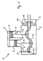
- the FIG. 1 shows a compressor 1 with a compressor housing 2 and arranged on the compressor housing 2 coupling device 3.
- the coupling device 3 is designed as a pneumatically actuated shut-off clutch.
- the coupling device 3 a pneumatic actuating cylinder 19, via the coupling means 18 at pneumatic loading, z.
- clutch plates or clutch plates are pressed against each other or separable from each other.
- the coupling device 3 connects a crankshaft 12 of the compressor 1 with a drive shaft of a drive device of a vehicle, not shown in detail, of a vehicle, for example the vehicle engine.
- the compressor 1 has a first cylinder 8 and a second cylinder 9.
- a first piston 6 is arranged in the first cylinder 8 .
- a second piston 7 is arranged in the second cylinder 9.
- the first piston 6 is connected to the crankshaft 12 via a first connecting rod 10 and corresponding bearings.
- the second piston 7 is also via a second connecting rod 11 via corresponding Bearing connected to the crankshaft 12.
- the storage of the piston 6, 7 and the crankshaft 12 in the corresponding bearing eyes of the connecting rods 10, 11 is in the FIG. 1 for the sake of simplicity only shown schematically. In practice, suitable sliding or roller bearings are used for this purpose.
- the cylinders 8, 9 are arranged in a cylinder housing 4 of the compressor 1.
- the cylinder housing 4 is part of the housing 2.
- valve and control block 5 On the cylinder housing 4, a valve and control block 5 is arranged, which includes, for example, the inlet and outlet valves for the compressed air intake and for the compressed air delivery to downstream units such as compressed air reservoir.
- the valve block 5 can be described in detail, for example, according to DE 197 451 18 A1 be educated.
- the compressor 1 has a lubricant supply.
- a lubricant for example, oil is used, for example, the engine oil of the vehicle engine.
- the lubricant supply of the compressor 1 has a lubricant connection 14 which is to be connected to the engine oil supply of the vehicle engine. From the lubricant port 14, a first lubricant passage 15 leads through the housing 2 to a lubricant supply groove 16 revolving around the crankshaft 12.
- the lubricant supply groove 16 is connected to a lubricant supply passage section 13 which extends in the form of a hollow passage within the crankshaft 12.
- the channel section 13 communicates with outlet points for the lubricant in the region of the connecting rods 10, 11, which are described below with reference to FIGS FIG. 2 will be explained in detail.
- the use of the circulating lubricant supply groove 16 has the advantage that the lubricant can be distributed on the circumference of the crankshaft 12 and, as a result, can be fed into the lubricant passage section 13 relatively quickly and uniformly.
- the lubricant is usually pressurized and is under a pressure of about 3 to 4 bar. As a result, a lubricant supply is independent of the movement of the compressor possible, ie even when stationary Compressor.
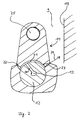
- FIG. 2 shows the connecting rod 11 in a sectional view.
- the connecting rod 11 has a connecting rod 25 which is connected to the cylinder 7.
- Another (lower) connecting rod eye comprises the crankshaft 12, which in the FIG. 2 also shown in section.
- a bearing for example a ball bearing, provided in the FIG. 2 is not explicitly shown to simplify the presentation.
- the passage portion 13 is connected to a radial lubricant portion 20 in the crankshaft 12, which serves to introduce the lubricant into the connecting rod 11.
- the connecting rod 11 has, in the region of the connecting rod receiving the crankshaft 12, a segment-like widened portion 21, which forms a channel between the crankshaft and the connecting rod inner side.
- the extended portion 21 may advantageously be designed as a recess within the connecting rod.
- the section 21 can also be designed as a groove in the crankshaft 12. It is crucial that a channel for forwarding the lubricant from the channel portion 13 to lubricant outlet 22, 23, is formed.
- the groove 21 passes the lubricant further to the lubricant outlet 22, 23, which are provided on both sides of the connecting rod 11. Also conceivable is an embodiment with only one lubricant outlet 22 or 23, but an increased lubricant throughput can be achieved through a plurality of lubricant outlets.
- the lubricant outlets 22, 23 are tapered in the direction of the lubricant outlet opening and thus designed in the manner of a nozzle. Due to the overpressure of the lubricant and the nozzle action of the lubricant outlets 22, 23, the lubricant is splashed out of the openings and hits, as in the FIG. 2 indicated by the arrow 24, on the cylinder wall 19. This ensures an early and good lubrication of the cylinder wall relative to the cylinder, even with temporarily switched off via the coupling device 3 compressor. 1
- the taper of the lubricant outlets 22, 23 may be continuous or stepped, with a linear or curved contour.
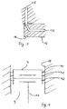
- FIG. 3 shows the inlet side connection of the crankshaft 12 to the lubricant port 14.
- the lubricant passage portion 13 is in communication with the circumferential groove 16 of the crankshaft 12.
- a connection to the lubricant channel 15 is ensured at each rotational angular position of the crankshaft, so that a secure and high throughput of lubricant through the channels 15, 13 is ensured.
- the lubricant supply channel 13, 15, 16, 20, 21 additionally on a lubricant supply gallery with a plurality of fixedly arranged in the crankcase of the compressor 1 lubricant nozzles.
- the lubricant nozzles are designed for molding the cylinder bore with the lubricant.
- the lubricant nozzles can be aligned with your outlet point on the cylinder bore or the cylinder wall 19. As a result, the lubrication of the compressor can be further improved.
- the FIG. 4 Sectionally shows the cylinder 9 with the piston 7.
- the piston 7, and possibly also the piston 6, are provided with arranged in circumferential grooves of the piston piston rings 40, 41, 42.
- the piston rings 40, 41 are formed as compression rings and provide an air seal of the above the piston 7 compression space relative to the lower crankcase. By using two compression rings increased density can be achieved compared to a compression ring.
- the piston ring 42 is formed as an oil scraper ring.
- the oil scraper ring should prevent the penetration of oil into the above the piston 7 compression space.
- the coating may advantageously contain chromium.
- the oil control ring 42 is formed chromed on its outer surface.
- the coupling device 3 projects over the housing 2 of the compressor 1 addition, that is, the coupling device is not, as from DE 20 2006 019 190 U1 known, integrated into the housing.
- the coupling device 3 protrudes at least with a coupling means 18, for example, the clutch disc or Lamellseil, containing area of the
Claims (11)
- Compresseur (1) pour la génération d'air comprimé dans un véhicule, comprenant au moins un piston (6, 7), un cylindre (8, 9), un vilebrequin (12), un raccord de lubrifiant (14) et un canal d'alimentation en lubrifiant (13, 15, 16, 20, 21), ainsi qu'un dispositif d'accouplement (3) au moyen duquel le vilebrequin (12) du compresseur (1) peut être connecté à un dispositif d'entraînement ou peut être séparé de celui-ci, caractérisé en ce que le canal d'alimentation en lubrifiant (13, 15, 16, 20, 21) débouche dans au moins une sortie de lubrifiant (22, 23) prévue à l'intérieur du compresseur (1), laquelle sortie de lubrifiant étant orientée au moins dans des positions de rotation déterminées du vilebrequin (12) vers une surface de déplacement de piston (19) du cylindre (8, 9).
- Compresseur selon la revendication 1, caractérisé en ce que le canal d'alimentation en lubrifiant (13, 15, 16, 20, 21) présente une section de canal (13) conduisant à travers le vilebrequin (12).
- Compresseur selon la revendication 2, caractérisé en ce que le vilebrequin (12) présente une rainure périphérique (16) en liaison avec un raccord de lubrifiant (14) en vue de guider le lubrifiant, laquelle rainure est connectée à la section de canal (13) conduisant à travers le vilebrequin (12) en vue de guider le lubrifiant.
- Compresseur selon la revendication 2 ou 3, caractérisé en ce qu'une bielle (10, 11) reliant le piston (6, 7) au vilebrequin (12) présente la sortie de lubrifiant (22, 23).
- Compresseur selon la revendication 4, caractérisé en ce que le canal d'alimentation en lubrifiant (13, 15, 16, 20, 21) présente une section de canal (21) formée entre la bielle (10, 11) et le vilebrequin (12).
- Compresseur selon la revendication 5, caractérisé en ce que la bielle (10, 11) présente une encoche (21) en tant que partie du canal d'alimentation en lubrifiant (13, 15, 16, 20, 21).
- Compresseur selon au moins l'une quelconque des revendications précédentes, caractérisé en ce que la sortie de lubrifiant (22, 23) est réalisée de manière à se rétrécir à la manière d'une buse dans la direction de l'ouverture de sortie de lubrifiant.
- Compresseur selon au moins l'une quelconque des revendications précédentes, caractérisé en ce que le canal d'alimentation en lubrifiant (13, 15, 16, 20, 21) présente une galerie d'alimentation en lubrifiant comprenant une pluralité de buses de lubrifiant disposées fixement dans le carter de vilebrequin du compresseur (1), les buses de lubrifiant étant prévues pour injecter du lubrifiant sur l'alésage du cylindre.
- Compresseur (1) pour la génération d'air comprimé dans un véhicule, comprenant au moins un piston (6, 7), en particulier selon au moins l'une quelconque des revendications précédentes, caractérisé en ce qu'une bague de grattage d'huile (42) est disposée au niveau du piston (6, 7), laquelle présente un revêtement réduisant l'abrasion.
- Compresseur selon la revendication 7, caractérisé en ce que le revêtement contient du chrome.
- Compresseur (1) selon au moins l'une quelconque des revendications précédentes, caractérisé en ce que le dispositif d'accouplement (3) est disposé au niveau du carter du compresseur (2) et fait saillie avec au moins une région contenant un moyen d'accouplement (18) hors du carter (2) du compresseur (1).
Applications Claiming Priority (2)
| Application Number | Priority Date | Filing Date | Title |
|---|---|---|---|
| DE102009018843A DE102009018843A1 (de) | 2009-04-28 | 2009-04-28 | Kompressor und Kupplungseinrichtung |
| PCT/EP2010/000226 WO2010124750A1 (fr) | 2009-04-28 | 2010-01-16 | Compresseur et dispositif d'accouplement |
Publications (3)
| Publication Number | Publication Date |
|---|---|
| EP2425135A1 EP2425135A1 (fr) | 2012-03-07 |
| EP2425135B1 true EP2425135B1 (fr) | 2014-01-15 |
| EP2425135B2 EP2425135B2 (fr) | 2017-08-02 |
Family
ID=41818937
Family Applications (1)
| Application Number | Title | Priority Date | Filing Date |
|---|---|---|---|
| EP10700306.3A Active EP2425135B2 (fr) | 2009-04-28 | 2010-01-16 | Compresseur et dispositif d'accouplement |
Country Status (7)
| Country | Link |
|---|---|
| US (1) | US9091257B2 (fr) |
| EP (1) | EP2425135B2 (fr) |
| JP (1) | JP5593507B2 (fr) |
| KR (1) | KR101286919B1 (fr) |
| CN (1) | CN102405351B (fr) |
| DE (1) | DE102009018843A1 (fr) |
| WO (1) | WO2010124750A1 (fr) |
Families Citing this family (2)
| Publication number | Priority date | Publication date | Assignee | Title |
|---|---|---|---|---|
| CA2937595C (fr) * | 2014-01-29 | 2022-05-31 | Nuovo Pignone Srl | Train de compresseur a moteur stirling |
| DE102016201208B4 (de) * | 2016-01-27 | 2024-01-11 | Knorr-Bremse Systeme für Nutzfahrzeuge GmbH | Kolbenkompressor mit Entlüftungseinrichtung |
Family Cites Families (33)
| Publication number | Priority date | Publication date | Assignee | Title |
|---|---|---|---|---|
| US1945374A (en) * | 1932-09-13 | 1934-01-30 | Papaefthemeou Demetrios | Piston assembly |
| DE2002470C2 (de) * | 1970-01-21 | 1982-09-09 | Daimler-Benz Ag, 7000 Stuttgart | Anordnung eines Luftpressers an einer Brennkraftmaschine |
| IT1205364B (it) * | 1978-02-16 | 1989-03-15 | Ass Eng Italia | Perfezionamento relativo al procedimento per la fabbricazione di anelli per pistoni ed anelli cosi ottenuti |
| JPS56101088A (en) * | 1980-01-16 | 1981-08-13 | Mitsubishi Electric Corp | Compressor |
| DE3042069A1 (de) † | 1980-11-07 | 1982-06-16 | Knorr-Bremse GmbH, 8000 München | Ventilvorrichtung fuer eine pneumatisch gesteuerte kompressor-abschaltkupplung |
| JPS57188075A (en) * | 1981-05-15 | 1982-11-18 | Fuji Photo Film Co Ltd | Electric signal recording method |
| EP0122015B1 (fr) | 1983-03-12 | 1989-01-18 | Grau Limited | Compresseur d'air |
| GB8306874D0 (en) * | 1983-03-12 | 1983-04-20 | Lucas Ind Plc | Air compressor |
| GB2162255B (en) | 1984-03-30 | 1988-02-03 | Grau Girling Limited | Multi-plate clutch in an air compressor |
| US4586875A (en) * | 1985-06-06 | 1986-05-06 | Thermo King Corporation | Refrigerant compressor bypass oil filter system |
| GB2182732A (en) | 1985-11-07 | 1987-05-20 | Bendix Ltd | Clutch-driven compressor assembly |
| GB2188108A (en) * | 1986-03-20 | 1987-09-23 | Bendix Ltd | Clutch for air compressor assembly |
| DE3703047C1 (de) * | 1987-02-03 | 1988-06-23 | Mtu Friedrichshafen Gmbh | Schmieroelkanal |
| EP0284388A3 (fr) * | 1987-03-26 | 1989-11-15 | Bendix Limited | Assemblage de compresseur entraíné par un embrayage |
| JPH0645668Y2 (ja) * | 1989-07-03 | 1994-11-24 | 三輪精機株式会社 | エアコンプレッサ |
| US5039285A (en) † | 1990-01-18 | 1991-08-13 | Tecumseh Products Company | Lubrication system of connecting rod, piston, and wrist pin for a compressor |
| US5469777A (en) * | 1994-07-05 | 1995-11-28 | Ford Motor Company | Piston assembly having abradable coating |
| US5713129A (en) † | 1996-05-16 | 1998-02-03 | Cummins Engine Company, Inc. | Method of manufacturing coated piston ring |
| DE19745118B4 (de) | 1997-10-11 | 2006-10-12 | Wabco Gmbh & Co.Ohg | Druckerzeugungsanlage |
| KR19990030450U (ko) * | 1997-12-30 | 1999-07-26 | 양재신 | 윤활성을 개선한 크랭크 샤프트 구조 |
| CA2350105A1 (fr) † | 1998-11-05 | 2000-05-18 | Hans Jensen Lubricators A/S | Systeme de lubrification pour moteurs diesel de grande taille |
| US6484847B2 (en) * | 2000-11-30 | 2002-11-26 | Tecumseh Products Company | Lubricant pump with magnetic and centrifugal traps |
| BR0101017B1 (pt) † | 2001-03-13 | 2008-11-18 | sistema de lubrificaÇço de pistço para compressor alternativo com motor linear. | |
| KR20040034082A (ko) * | 2002-10-21 | 2004-04-28 | 대우종합기계 주식회사 | 차량용 클러치 타잎 공기압축기 |
| EP1557544B1 (fr) * | 2002-10-24 | 2008-08-13 | Taiho Kogyo Co., Ltd. | Dispositif d'alimentation en huile pour vilebrequin de moteur |
| KR20040097413A (ko) * | 2003-05-12 | 2004-11-18 | 현대자동차주식회사 | 피스톤 냉각용 오일 공급홀 구조 |
| US6907848B2 (en) * | 2003-10-09 | 2005-06-21 | General Motors Corporation | Connecting rod with lubricant tube |
| US20080252019A1 (en) * | 2005-12-25 | 2008-10-16 | Xiuming Yu | Oil sealing ring |
| US7249577B1 (en) * | 2006-03-14 | 2007-07-31 | Gm Global Technology Operations, Inc. | Connecting rod with oil squirter |
| DE202006019190U1 (de) | 2006-12-15 | 2008-04-24 | Kwd Kupplungswerk Dresden Gmbh | Federdruck-Lamellenkupplung für Kompressoren |
| US7954600B2 (en) * | 2007-02-13 | 2011-06-07 | Honda Motor Co., Ltd. | Crankshaft lubrication system |
| US8763734B2 (en) † | 2007-04-05 | 2014-07-01 | Haldex Brake Corporation | Drive through air compressor with cone clutch |
| DE102007027815A1 (de) † | 2007-06-13 | 2008-12-24 | Federal-Mogul Burscheid Gmbh | Ölabstreifring |
-
2009
- 2009-04-28 DE DE102009018843A patent/DE102009018843A1/de not_active Ceased
-
2010
- 2010-01-16 WO PCT/EP2010/000226 patent/WO2010124750A1/fr active Application Filing
- 2010-01-16 JP JP2012508916A patent/JP5593507B2/ja active Active
- 2010-01-16 EP EP10700306.3A patent/EP2425135B2/fr active Active
- 2010-01-16 KR KR1020117016957A patent/KR101286919B1/ko active IP Right Grant
- 2010-01-16 US US13/262,894 patent/US9091257B2/en active Active
- 2010-01-16 CN CN201080017319.5A patent/CN102405351B/zh active Active
Also Published As
| Publication number | Publication date |
|---|---|
| EP2425135B2 (fr) | 2017-08-02 |
| US20120039728A1 (en) | 2012-02-16 |
| CN102405351B (zh) | 2015-10-14 |
| EP2425135A1 (fr) | 2012-03-07 |
| JP2012525541A (ja) | 2012-10-22 |
| US9091257B2 (en) | 2015-07-28 |
| CN102405351A (zh) | 2012-04-04 |
| WO2010124750A1 (fr) | 2010-11-04 |
| KR101286919B1 (ko) | 2013-07-23 |
| KR20110096171A (ko) | 2011-08-29 |
| JP5593507B2 (ja) | 2014-09-24 |
| DE102009018843A1 (de) | 2010-11-04 |
Similar Documents
| Publication | Publication Date | Title |
|---|---|---|
| DE69929916T2 (de) | Brennstoffeinspritzpumpe | |
| DE102011118622B4 (de) | Axialkolbenmaschine mit Auslasssteuerung | |
| EP2213851B1 (fr) | Dispositif d'alimentation en huile pour lubrifier un cylindre et/ou refroidir un piston | |
| DE102017102313B4 (de) | Kurbelwelle einer Brennkraftmaschine | |
| DE102006031032A1 (de) | Pumpenstößel | |
| DE3203312C2 (de) | Von einer Schmierölpumpe gespeistes Schmierölverteilungssystem für eine Brennkraftmaschine | |
| EP3502494B1 (fr) | Dispositif de lubrification d'un palier de bielle | |
| WO2018083256A1 (fr) | Bielle réglable en longueur comportant une unité cylindre-piston pourvue de plusieurs joints de piston | |
| DE102012207951B4 (de) | Kolben einer Brennkraftmaschine | |
| DE102006059600A1 (de) | Antriebseinheit, geeignet für Hochleistungs- Verdichter, - Pumpen, -Bremsen, Kraftantriebe, sowie die dazugehörigen Maschinen | |
| EP3502493B1 (fr) | Dispositif et procédé de lubrification d'un palier de bielle | |
| DE102017122869B4 (de) | Kurbeltrieb für eine Hubkolbenmaschine | |
| EP2425135B1 (fr) | Compresseur et dispositif d'accouplement | |
| DE102017201741B4 (de) | Kolben-Pleuel-Vorrichtung zur direkten Kolbenschmierung und -kühlung | |
| DE102010046031A1 (de) | Kompressor mit Kupplungseinrichtung | |
| DE102015226437A1 (de) | Hydrostatische Axialkolbenmaschine mit verstellbarem Hubvolumen | |
| DE102015223037A1 (de) | Vibrationsantrieb mit hydraulischer Pulserzeugungsvorrichtung | |
| DE102015009568B4 (de) | Brennkraftmaschine mit einer Steuereinrichtung zur gezielten Ansteuerung einer Kolbenkühldüse oder eines Kolbenkühlkanals sowie Verfahren zum Betreiben einer Brennkraftmaschine | |
| DE102018132718B4 (de) | Kurbeltrieb für eine Hubkolbenmaschine | |
| DE102020125000A1 (de) | Reihenkolbenpumpe | |
| DE10347085B3 (de) | Hydrostatische Kolbenmaschine mit zwei hydraulischen Kreisläufen | |
| DE102011053148B4 (de) | Radialkolbenpumpe | |
| DE2425361C3 (de) | Kraftstoffverteilereinspritzpumpe für Brennkraftmaschinen | |
| DE10017780B4 (de) | Kolbenmaschine | |
| DE102014009484A1 (de) | Stelleinrichtung zum variablen Einstellen wenigstens eines Verdichtungsverhältnisses eines Zylinders einer Hubkolbenmaschine |
Legal Events
| Date | Code | Title | Description |
|---|---|---|---|
| PUAI | Public reference made under article 153(3) epc to a published international application that has entered the european phase |
Free format text: ORIGINAL CODE: 0009012 |
|
| 17P | Request for examination filed |
Effective date: 20111128 |
|
| AK | Designated contracting states |
Kind code of ref document: A1 Designated state(s): AT BE BG CH CY CZ DE DK EE ES FI FR GB GR HR HU IE IS IT LI LT LU LV MC MK MT NL NO PL PT RO SE SI SK SM TR |
|
| DAX | Request for extension of the european patent (deleted) | ||
| GRAP | Despatch of communication of intention to grant a patent |
Free format text: ORIGINAL CODE: EPIDOSNIGR1 |
|
| INTG | Intention to grant announced |
Effective date: 20130930 |
|
| INTG | Intention to grant announced |
Effective date: 20131008 |
|
| GRAS | Grant fee paid |
Free format text: ORIGINAL CODE: EPIDOSNIGR3 |
|
| GRAA | (expected) grant |
Free format text: ORIGINAL CODE: 0009210 |
|
| AK | Designated contracting states |
Kind code of ref document: B1 Designated state(s): AT BE BG CH CY CZ DE DK EE ES FI FR GB GR HR HU IE IS IT LI LT LU LV MC MK MT NL NO PL PT RO SE SI SK SM TR |
|
| REG | Reference to a national code |
Ref country code: GB Ref legal event code: FG4D Free format text: NOT ENGLISH Ref country code: CH Ref legal event code: EP |
|
| REG | Reference to a national code |
Ref country code: AT Ref legal event code: REF Ref document number: 649964 Country of ref document: AT Kind code of ref document: T Effective date: 20140215 |
|
| REG | Reference to a national code |
Ref country code: IE Ref legal event code: FG4D Free format text: LANGUAGE OF EP DOCUMENT: GERMAN |
|
| REG | Reference to a national code |
Ref country code: DE Ref legal event code: R096 Ref document number: 502010005952 Country of ref document: DE Effective date: 20140227 |
|
| REG | Reference to a national code |
Ref country code: NL Ref legal event code: T3 |
|
| REG | Reference to a national code |
Ref country code: SE Ref legal event code: TRGR |
|
| REG | Reference to a national code |
Ref country code: LT Ref legal event code: MG4D |
|
| BERE | Be: lapsed |
Owner name: WABCO G.M.B.H. Effective date: 20140131 |
|
| PG25 | Lapsed in a contracting state [announced via postgrant information from national office to epo] |
Ref country code: IS Free format text: LAPSE BECAUSE OF FAILURE TO SUBMIT A TRANSLATION OF THE DESCRIPTION OR TO PAY THE FEE WITHIN THE PRESCRIBED TIME-LIMIT Effective date: 20140515 Ref country code: NO Free format text: LAPSE BECAUSE OF FAILURE TO SUBMIT A TRANSLATION OF THE DESCRIPTION OR TO PAY THE FEE WITHIN THE PRESCRIBED TIME-LIMIT Effective date: 20140415 Ref country code: LT Free format text: LAPSE BECAUSE OF FAILURE TO SUBMIT A TRANSLATION OF THE DESCRIPTION OR TO PAY THE FEE WITHIN THE PRESCRIBED TIME-LIMIT Effective date: 20140115 |
|
| PG25 | Lapsed in a contracting state [announced via postgrant information from national office to epo] |
Ref country code: FI Free format text: LAPSE BECAUSE OF FAILURE TO SUBMIT A TRANSLATION OF THE DESCRIPTION OR TO PAY THE FEE WITHIN THE PRESCRIBED TIME-LIMIT Effective date: 20140115 Ref country code: PT Free format text: LAPSE BECAUSE OF FAILURE TO SUBMIT A TRANSLATION OF THE DESCRIPTION OR TO PAY THE FEE WITHIN THE PRESCRIBED TIME-LIMIT Effective date: 20140515 Ref country code: ES Free format text: LAPSE BECAUSE OF FAILURE TO SUBMIT A TRANSLATION OF THE DESCRIPTION OR TO PAY THE FEE WITHIN THE PRESCRIBED TIME-LIMIT Effective date: 20140115 Ref country code: CY Free format text: LAPSE BECAUSE OF FAILURE TO SUBMIT A TRANSLATION OF THE DESCRIPTION OR TO PAY THE FEE WITHIN THE PRESCRIBED TIME-LIMIT Effective date: 20140115 |
|
| REG | Reference to a national code |
Ref country code: CH Ref legal event code: PL |
|
| PG25 | Lapsed in a contracting state [announced via postgrant information from national office to epo] |
Ref country code: LV Free format text: LAPSE BECAUSE OF FAILURE TO SUBMIT A TRANSLATION OF THE DESCRIPTION OR TO PAY THE FEE WITHIN THE PRESCRIBED TIME-LIMIT Effective date: 20140115 Ref country code: HR Free format text: LAPSE BECAUSE OF FAILURE TO SUBMIT A TRANSLATION OF THE DESCRIPTION OR TO PAY THE FEE WITHIN THE PRESCRIBED TIME-LIMIT Effective date: 20140115 |
|
| REG | Reference to a national code |
Ref country code: DE Ref legal event code: R026 Ref document number: 502010005952 Country of ref document: DE |
|
| PLBI | Opposition filed |
Free format text: ORIGINAL CODE: 0009260 |
|
| PG25 | Lapsed in a contracting state [announced via postgrant information from national office to epo] |
Ref country code: CZ Free format text: LAPSE BECAUSE OF FAILURE TO SUBMIT A TRANSLATION OF THE DESCRIPTION OR TO PAY THE FEE WITHIN THE PRESCRIBED TIME-LIMIT Effective date: 20140115 Ref country code: LI Free format text: LAPSE BECAUSE OF NON-PAYMENT OF DUE FEES Effective date: 20140131 Ref country code: DK Free format text: LAPSE BECAUSE OF FAILURE TO SUBMIT A TRANSLATION OF THE DESCRIPTION OR TO PAY THE FEE WITHIN THE PRESCRIBED TIME-LIMIT Effective date: 20140115 Ref country code: EE Free format text: LAPSE BECAUSE OF FAILURE TO SUBMIT A TRANSLATION OF THE DESCRIPTION OR TO PAY THE FEE WITHIN THE PRESCRIBED TIME-LIMIT Effective date: 20140115 Ref country code: MC Free format text: LAPSE BECAUSE OF FAILURE TO SUBMIT A TRANSLATION OF THE DESCRIPTION OR TO PAY THE FEE WITHIN THE PRESCRIBED TIME-LIMIT Effective date: 20140115 Ref country code: RO Free format text: LAPSE BECAUSE OF FAILURE TO SUBMIT A TRANSLATION OF THE DESCRIPTION OR TO PAY THE FEE WITHIN THE PRESCRIBED TIME-LIMIT Effective date: 20140115 Ref country code: CH Free format text: LAPSE BECAUSE OF NON-PAYMENT OF DUE FEES Effective date: 20140131 |
|
| REG | Reference to a national code |
Ref country code: IE Ref legal event code: MM4A |
|
| 26 | Opposition filed |
Opponent name: KNORR-BREMSE SYSTEME FUER NUTZFAHRZEUGE GMBH Effective date: 20141014 |
|
| PLAX | Notice of opposition and request to file observation + time limit sent |
Free format text: ORIGINAL CODE: EPIDOSNOBS2 |
|
| PG25 | Lapsed in a contracting state [announced via postgrant information from national office to epo] |
Ref country code: SK Free format text: LAPSE BECAUSE OF FAILURE TO SUBMIT A TRANSLATION OF THE DESCRIPTION OR TO PAY THE FEE WITHIN THE PRESCRIBED TIME-LIMIT Effective date: 20140115 Ref country code: PL Free format text: LAPSE BECAUSE OF FAILURE TO SUBMIT A TRANSLATION OF THE DESCRIPTION OR TO PAY THE FEE WITHIN THE PRESCRIBED TIME-LIMIT Effective date: 20140115 |
|
| GBPC | Gb: european patent ceased through non-payment of renewal fee |
Effective date: 20140415 |
|
| REG | Reference to a national code |
Ref country code: DE Ref legal event code: R026 Ref document number: 502010005952 Country of ref document: DE Effective date: 20141014 |
|
| PLBB | Reply of patent proprietor to notice(s) of opposition received |
Free format text: ORIGINAL CODE: EPIDOSNOBS3 |
|
| PG25 | Lapsed in a contracting state [announced via postgrant information from national office to epo] |
Ref country code: GB Free format text: LAPSE BECAUSE OF NON-PAYMENT OF DUE FEES Effective date: 20140415 Ref country code: BE Free format text: LAPSE BECAUSE OF NON-PAYMENT OF DUE FEES Effective date: 20140131 Ref country code: IE Free format text: LAPSE BECAUSE OF NON-PAYMENT OF DUE FEES Effective date: 20140116 |
|
| PG25 | Lapsed in a contracting state [announced via postgrant information from national office to epo] |
Ref country code: SI Free format text: LAPSE BECAUSE OF FAILURE TO SUBMIT A TRANSLATION OF THE DESCRIPTION OR TO PAY THE FEE WITHIN THE PRESCRIBED TIME-LIMIT Effective date: 20140115 |
|
| REG | Reference to a national code |
Ref country code: FR Ref legal event code: PLFP Year of fee payment: 7 |
|
| PG25 | Lapsed in a contracting state [announced via postgrant information from national office to epo] |
Ref country code: MT Free format text: LAPSE BECAUSE OF FAILURE TO SUBMIT A TRANSLATION OF THE DESCRIPTION OR TO PAY THE FEE WITHIN THE PRESCRIBED TIME-LIMIT Effective date: 20140115 |
|
| REG | Reference to a national code |
Ref country code: AT Ref legal event code: MM01 Ref document number: 649964 Country of ref document: AT Kind code of ref document: T Effective date: 20150116 |
|
| PG25 | Lapsed in a contracting state [announced via postgrant information from national office to epo] |
Ref country code: SM Free format text: LAPSE BECAUSE OF FAILURE TO SUBMIT A TRANSLATION OF THE DESCRIPTION OR TO PAY THE FEE WITHIN THE PRESCRIBED TIME-LIMIT Effective date: 20140115 |
|
| PG25 | Lapsed in a contracting state [announced via postgrant information from national office to epo] |
Ref country code: AT Free format text: LAPSE BECAUSE OF NON-PAYMENT OF DUE FEES Effective date: 20150116 |
|
| PG25 | Lapsed in a contracting state [announced via postgrant information from national office to epo] |
Ref country code: GR Free format text: LAPSE BECAUSE OF FAILURE TO SUBMIT A TRANSLATION OF THE DESCRIPTION OR TO PAY THE FEE WITHIN THE PRESCRIBED TIME-LIMIT Effective date: 20140416 Ref country code: BG Free format text: LAPSE BECAUSE OF FAILURE TO SUBMIT A TRANSLATION OF THE DESCRIPTION OR TO PAY THE FEE WITHIN THE PRESCRIBED TIME-LIMIT Effective date: 20140115 Ref country code: IT Free format text: LAPSE BECAUSE OF FAILURE TO SUBMIT A TRANSLATION OF THE DESCRIPTION OR TO PAY THE FEE WITHIN THE PRESCRIBED TIME-LIMIT Effective date: 20140115 |
|
| PG25 | Lapsed in a contracting state [announced via postgrant information from national office to epo] |
Ref country code: LU Free format text: LAPSE BECAUSE OF NON-PAYMENT OF DUE FEES Effective date: 20140116 Ref country code: HU Free format text: LAPSE BECAUSE OF FAILURE TO SUBMIT A TRANSLATION OF THE DESCRIPTION OR TO PAY THE FEE WITHIN THE PRESCRIBED TIME-LIMIT; INVALID AB INITIO Effective date: 20100116 |
|
| REG | Reference to a national code |
Ref country code: FR Ref legal event code: PLFP Year of fee payment: 8 |
|
| PUAH | Patent maintained in amended form |
Free format text: ORIGINAL CODE: 0009272 |
|
| STAA | Information on the status of an ep patent application or granted ep patent |
Free format text: STATUS: PATENT MAINTAINED AS AMENDED |
|
| 27A | Patent maintained in amended form |
Effective date: 20170802 |
|
| AK | Designated contracting states |
Kind code of ref document: B2 Designated state(s): AT BE BG CH CY CZ DE DK EE ES FI FR GB GR HR HU IE IS IT LI LT LU LV MC MK MT NL NO PL PT RO SE SI SK SM TR |
|
| REG | Reference to a national code |
Ref country code: DE Ref legal event code: R102 Ref document number: 502010005952 Country of ref document: DE |
|
| REG | Reference to a national code |
Ref country code: NL Ref legal event code: FP |
|
| REG | Reference to a national code |
Ref country code: SE Ref legal event code: RPEO |
|
| REG | Reference to a national code |
Ref country code: DE Ref legal event code: R081 Ref document number: 502010005952 Country of ref document: DE Owner name: WABCO EUROPE BVBA, BE Free format text: FORMER OWNER: WABCO GMBH, 30453 HANNOVER, DE |
|
| REG | Reference to a national code |
Ref country code: FR Ref legal event code: PLFP Year of fee payment: 9 |
|
| PG25 | Lapsed in a contracting state [announced via postgrant information from national office to epo] |
Ref country code: MK Free format text: LAPSE BECAUSE OF FAILURE TO SUBMIT A TRANSLATION OF THE DESCRIPTION OR TO PAY THE FEE WITHIN THE PRESCRIBED TIME-LIMIT Effective date: 20140115 |
|
| REG | Reference to a national code |
Ref country code: DE Ref legal event code: R081 Ref document number: 502010005952 Country of ref document: DE Owner name: ZF CV SYSTEMS EUROPE BV, BE Free format text: FORMER OWNER: WABCO EUROPE BVBA, BRUESSEL, BE |
|
| PGFP | Annual fee paid to national office [announced via postgrant information from national office to epo] |
Ref country code: TR Payment date: 20230116 Year of fee payment: 14 |
|
| P01 | Opt-out of the competence of the unified patent court (upc) registered |
Effective date: 20230528 |
|
| PGFP | Annual fee paid to national office [announced via postgrant information from national office to epo] |
Ref country code: SE Payment date: 20231213 Year of fee payment: 15 Ref country code: NL Payment date: 20231215 Year of fee payment: 15 Ref country code: FR Payment date: 20231212 Year of fee payment: 15 |
|
| PGFP | Annual fee paid to national office [announced via postgrant information from national office to epo] |
Ref country code: DE Payment date: 20231205 Year of fee payment: 15 |