EP2423632B1 - Heat exchanger and air conditioner having the heat exchanger mounted therein - Google Patents
Heat exchanger and air conditioner having the heat exchanger mounted therein Download PDFInfo
- Publication number
- EP2423632B1 EP2423632B1 EP09843678.5A EP09843678A EP2423632B1 EP 2423632 B1 EP2423632 B1 EP 2423632B1 EP 09843678 A EP09843678 A EP 09843678A EP 2423632 B1 EP2423632 B1 EP 2423632B1
- Authority
- EP
- European Patent Office
- Prior art keywords
- water
- heat exchanger
- guide members
- water guide
- corrugated fins
- Prior art date
- Legal status (The legal status is an assumption and is not a legal conclusion. Google has not performed a legal analysis and makes no representation as to the accuracy of the status listed.)
- Not-in-force
Links
Images


Classifications
-
- F—MECHANICAL ENGINEERING; LIGHTING; HEATING; WEAPONS; BLASTING
- F28—HEAT EXCHANGE IN GENERAL
- F28F—DETAILS OF HEAT-EXCHANGE AND HEAT-TRANSFER APPARATUS, OF GENERAL APPLICATION
- F28F1/00—Tubular elements; Assemblies of tubular elements
- F28F1/10—Tubular elements and assemblies thereof with means for increasing heat-transfer area, e.g. with fins, with projections, with recesses
- F28F1/12—Tubular elements and assemblies thereof with means for increasing heat-transfer area, e.g. with fins, with projections, with recesses the means being only outside the tubular element
- F28F1/24—Tubular elements and assemblies thereof with means for increasing heat-transfer area, e.g. with fins, with projections, with recesses the means being only outside the tubular element and extending transversely
- F28F1/30—Tubular elements and assemblies thereof with means for increasing heat-transfer area, e.g. with fins, with projections, with recesses the means being only outside the tubular element and extending transversely the means being attachable to the element
-
- F—MECHANICAL ENGINEERING; LIGHTING; HEATING; WEAPONS; BLASTING
- F28—HEAT EXCHANGE IN GENERAL
- F28D—HEAT-EXCHANGE APPARATUS, NOT PROVIDED FOR IN ANOTHER SUBCLASS, IN WHICH THE HEAT-EXCHANGE MEDIA DO NOT COME INTO DIRECT CONTACT
- F28D1/00—Heat-exchange apparatus having stationary conduit assemblies for one heat-exchange medium only, the media being in contact with different sides of the conduit wall, in which the other heat-exchange medium is a large body of fluid, e.g. domestic or motor car radiators
- F28D1/02—Heat-exchange apparatus having stationary conduit assemblies for one heat-exchange medium only, the media being in contact with different sides of the conduit wall, in which the other heat-exchange medium is a large body of fluid, e.g. domestic or motor car radiators with heat-exchange conduits immersed in the body of fluid
- F28D1/04—Heat-exchange apparatus having stationary conduit assemblies for one heat-exchange medium only, the media being in contact with different sides of the conduit wall, in which the other heat-exchange medium is a large body of fluid, e.g. domestic or motor car radiators with heat-exchange conduits immersed in the body of fluid with tubular conduits
- F28D1/053—Heat-exchange apparatus having stationary conduit assemblies for one heat-exchange medium only, the media being in contact with different sides of the conduit wall, in which the other heat-exchange medium is a large body of fluid, e.g. domestic or motor car radiators with heat-exchange conduits immersed in the body of fluid with tubular conduits the conduits being straight
- F28D1/0535—Heat-exchange apparatus having stationary conduit assemblies for one heat-exchange medium only, the media being in contact with different sides of the conduit wall, in which the other heat-exchange medium is a large body of fluid, e.g. domestic or motor car radiators with heat-exchange conduits immersed in the body of fluid with tubular conduits the conduits being straight the conduits having a non-circular cross-section
- F28D1/05366—Assemblies of conduits connected to common headers, e.g. core type radiators
- F28D1/05383—Assemblies of conduits connected to common headers, e.g. core type radiators with multiple rows of conduits or with multi-channel conduits
-
- F—MECHANICAL ENGINEERING; LIGHTING; HEATING; WEAPONS; BLASTING
- F28—HEAT EXCHANGE IN GENERAL
- F28F—DETAILS OF HEAT-EXCHANGE AND HEAT-TRANSFER APPARATUS, OF GENERAL APPLICATION
- F28F1/00—Tubular elements; Assemblies of tubular elements
- F28F1/10—Tubular elements and assemblies thereof with means for increasing heat-transfer area, e.g. with fins, with projections, with recesses
- F28F1/12—Tubular elements and assemblies thereof with means for increasing heat-transfer area, e.g. with fins, with projections, with recesses the means being only outside the tubular element
- F28F1/126—Tubular elements and assemblies thereof with means for increasing heat-transfer area, e.g. with fins, with projections, with recesses the means being only outside the tubular element consisting of zig-zag shaped fins
-
- F—MECHANICAL ENGINEERING; LIGHTING; HEATING; WEAPONS; BLASTING
- F28—HEAT EXCHANGE IN GENERAL
- F28F—DETAILS OF HEAT-EXCHANGE AND HEAT-TRANSFER APPARATUS, OF GENERAL APPLICATION
- F28F1/00—Tubular elements; Assemblies of tubular elements
- F28F1/10—Tubular elements and assemblies thereof with means for increasing heat-transfer area, e.g. with fins, with projections, with recesses
- F28F1/12—Tubular elements and assemblies thereof with means for increasing heat-transfer area, e.g. with fins, with projections, with recesses the means being only outside the tubular element
- F28F1/24—Tubular elements and assemblies thereof with means for increasing heat-transfer area, e.g. with fins, with projections, with recesses the means being only outside the tubular element and extending transversely
- F28F1/32—Tubular elements and assemblies thereof with means for increasing heat-transfer area, e.g. with fins, with projections, with recesses the means being only outside the tubular element and extending transversely the means having portions engaging further tubular elements
-
- F—MECHANICAL ENGINEERING; LIGHTING; HEATING; WEAPONS; BLASTING
- F28—HEAT EXCHANGE IN GENERAL
- F28F—DETAILS OF HEAT-EXCHANGE AND HEAT-TRANSFER APPARATUS, OF GENERAL APPLICATION
- F28F17/00—Removing ice or water from heat-exchange apparatus
- F28F17/005—Means for draining condensates from heat exchangers, e.g. from evaporators
-
- F—MECHANICAL ENGINEERING; LIGHTING; HEATING; WEAPONS; BLASTING
- F28—HEAT EXCHANGE IN GENERAL
- F28F—DETAILS OF HEAT-EXCHANGE AND HEAT-TRANSFER APPARATUS, OF GENERAL APPLICATION
- F28F9/00—Casings; Header boxes; Auxiliary supports for elements; Auxiliary members within casings
- F28F9/02—Header boxes; End plates
Definitions
- the present invention relates to a side-flow type parallel-flow heat exchanger and an air conditioner provided therewith.
- JP 7-55 380 discloses a heat exchanger according to the preamble of claim 1.
- a parallel-flow type heat exchanger having a plurality of flat tubes arranged between a plurality of header pipes such that a plurality of refrigerant passages in the flat tubes communicate with insides of the header pipes, and having fins such as corrugated fins arranged between the flat tubes, is widely used in, for example, vehicle air conditioners or outdoor units of air conditioners for buildings.
- FIG. 11 An example of conventional side-flow type parallel-flow heat exchangers is shown in Fig. 11 .
- the upper side of the sheet is the upper side in the vertical direction and the lower side of the sheet is the lower side in the vertical direction.
- the heat exchanger 1 is provided with two vertical header pipes 2 and 3 arranged parallel to each other at an interval in the horizontal direction and a plurality of horizontal flat tubes 4 arranged between the header pipes 2 and 3 at predetermined pitches in the vertical direction.
- the flat tubes 4 are elongate and formed of a metal by extrusion, and inside them are formed refrigerant passages 5 through which refrigerant flows.
- the flat tubes 4 are arranged such that the extrusion direction, which is also the length direction of the flat tubes 4, is horizontal, and thus the direction in which the refrigerant flows through the refrigerant passages 5 is also horizontal.
- a plurality of refrigerant passages 5 of a same sectional shape and area are arranged in the depth direction in Fig. 11 , so that the vertical section of each of the flat tubes 4 has a harmonica-like shape.
- Each of the refrigerant passages 5 communicates with the insides of the header pipes 2 and 3.
- Corrugated fins 6 are disposed between adjacent ones of the flat tubes 4.
- the header pipes 2 and 3, the flat tubes 4, and the corrugated fins 6 are all made of a metal having high thermal conductivity, such as aluminum.
- the flat tubes 4 are fixed to the header pipes 2 and 3, and the corrugated fins 6 are fixed to the flat tubes 4 by brazing or by welding.
- refrigerant gates 7 and 8 are formed only on the header pipe 3 side.
- two partition panels 9a and 9c are provided at an interval in the vertical direction.
- a partition 9b is provided at the height intermediate between the partition plates 9a and 9c.
- the refrigerant flows in through the lower refrigerant gate 7 as shown by a solid line arrow in Fig. 11 .
- the refrigerant that has entered through the refrigerant gate 7 is blocked by the partition panel 9a to be directed to the header pipe 2 through some of the flat tubes 4. This flow of the refrigerant is indicated by a left-pointing block arrow.
- the refrigerant that has entered the header pipe 2 is blocked by the partition panel 9b to be directed to the header pipe 3 through different ones of the flat tubes 4. This flow of the refrigerant is indicated by a right-pointing block arrow.
- the refrigerant that has entered the header pipe 3 is blocked by the partition panel 9c to be directed to the header pipe 3 again through still different ones of the flat tubes 4. This flow of the refrigerant is indicated by another left-pointing block arrow.
- the refrigerant that has entered the header pipe 2 turns around to be directed to the header pipe 3 again through still different ones of the flat tubes 4. This flow of the refrigerant is indicated by another right-pointing block arrow.
- the refrigerant that has entered the header pipe 3 flows out through the refrigerant gate 8. In this way, the refrigerant flows from bottom to top forming a zigzag passage.
- the flow direction of the refrigerant is reversed. That is, the refrigerant flows from top to bottom forming a zigzag passage in the following manner: the refrigerant enters the header pipe 3 through the refrigerant gate 8 as shown by the dotted-line arrow in Fig.
- the refrigerant that has entered the header pipe 3 is blocked by the partition panel 9c to be directed to the header pipe 2 through some of the flat tubes 4; the refrigerant that has entered the header pipe 2 is blocked by the partition panel 9b to be directed to the header pipe 3 through different ones of the flat tubes 4; the refrigerant that has entered the header pipe 3 is blocked by the partition panel 9a to be directed to the header pipe 2 again through still different ones of the flat tubes 4; the refrigerant that has entered the header pipe 2 turns to be directed to the header pipe 3 again through still different ones of the flat tubes 4; and then the refrigerant flows out through the refrigerant gate 7 as indicated by another dotted-line arrow.
- condensate water is converted to frost on the surface of the heat exchanger if the temperature is low. The conversion may even proceed from frost to ice.
- the term "condensate water” is intended to include within its scope so-called defrost water, that is, water resulting from melting of such frost or ice.
- Patent Document 1 suggests a method of promoting drainage from a side-flow type parallel-flow heat exchanger.
- drainage guides are disposed in contact with corrugated fins on a side of the heat exchanger where condensate water is collected.
- the drainage guides are linear members, and disposed to be tilted with respect to flat tubes. At least one of the two ends of each drainage guide is led to a lower-end side or a side-end side of the heat exchanger.
- JP7-55380 relates to a heat exchanger wherein the width of a corrugated fin is larger than the width of a tube while the parts of the fin, longer than the width of the tube are connected to the tube under a condition that the parts are extended to the upstream side and the downstream side of the tube. Further, an engaging part, having the holding depth of the tube, which is equal to the thickness of the tube, is formed on the curved part of the lower side of the corrugated fin while the corrugated fin is connected to the tube under the condition that the engaging part holes the tube.
- Japanese utility model JP60-95482 relates to a heat exchanger for use in laundry drying machines to remove moist from hot air that has passed through laundry by means of condensation. Condensate water is formed on the internal surface of a pipe in which the hot air flows.
- Patent Literature 1 JP-A-2007-285673
- the drainage guide described in Patent Document 1 itself blocks the flow of air passing between corrugated fins, and this is a cause of the degradation of the heat exchange performance of the heat exchanger.
- the present invention has been made in view of this problem, and an object of the present invention is to improve the condensate-water drainage capability of a side-flow type parallel-flow heat exchanger without reducing ventilation therethrough. Another object of the present invention is to provide a high-performance air conditioner provided with such a side-flow type parallel-flow heat exchanger.
- a side-flow type parallel-flow heat exchanger is provided in accordance with claim 1.
- the surface tension of the condensate water collected at the edges of the corrugated fins is exerted on the water guide members disposed on the flat tube side, and bridges of the condensate water formed at the edges of the corrugated fins are broken.
- the bridges of the condensate water are broken one after another like a chain reaction, and the condensate water is quickly drained away.
- ventilation through the corrugated fins is not reduced due to condensate water, and thus good heat exchange performance can be obtained.
- the water guide members are inserted into the gaps between adjacent ones of the protruding portions of the corrugated fins, the water guide members do not block air from flowing through the corrugated fins.
- the water guide members be water-absorbent members and be in contact with the edges of the corrugated fins.
- This structure facilitates procurement of the water guide members and exertion of the surface tension of condensate water on them.
- the water guide members be non-water-absorbent members, and that portions of the water guide members on which the surface tension of the condensate water is exerted do not protrude from the edges of the corrugated fins.
- the water guide members extend deep enough to fill the gaps from entrances to rear ends of the gaps.
- the water guide members can be fitted to be in contact with edges of the corrugated fins merely by pushing them in until they hit the rear ends of the gaps, leading to easy assembly. Furthermore, volumes of the water guide members are increased, and this enhances condensate-water attraction performance. Moreover, the water guide members are less likely to drop off from the gaps even if they are shaken while being transported or vibration is transmitted thereto from a compressor.
- an air conditioner has the heat exchanger of any one of claims 1 to 5 incorporated in an outdoor unit.
- an air conditioner has the heat exchanger of any one of claims 1 to 5 incorporated in an indoor unit.
- the surface tension of condensate water collected at the edges of the corrugated fins is exerted on the water guide members disposed on the flat tube side, and bridges that the condensate water forms at the edges of the corrugated fins are broken.
- the bridges of the condensate water are broken one after another like a chain reaction, and the condensate water is quickly drained away.
- the water guide members are positioned such that they do not block air from flowing through the corrugated fins, the amount of air passing through the corrugated fins is less likely to be reduced due to condensate water, and thus good heat-exchange performance of the heat exchanger can be constantly secured.
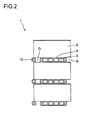
- Figs. 1 to 3 each show the structure of part of a side-flow type parallel-flow heat exchanger 1.
- a plurality of linear water guide members 10 are arranged at predetermined intervals on a condensate-water-collection side face of the heat exchanger 1.
- Each of the water guide members 10 is an assembly of fibers (preferably, synthetic fibers), that is, a so-called "cord”.
- edges of the corrugated fins 6 protrude from edges of the flat tubes 4.
- the water guide members 10 are inserted into gaps G between the protruding portions.
- the depth of the insertion should be such that water accumulated at the edges of the corrugated fins 6 can maintain its surface tension exerted on the water guide members.
- the water guide members 10 are inserted into all of the gaps G between the protruding portions of the corrugated fins 6.
- the water guide members 10 disposed in this way allow smooth drainage of condensate water away from the corrugated fins 6, attracting the condensate water collected on the corrugated fins 6.
- the mechanism of the attraction is as follows.
- a bridging phenomenon formation of a water film
- a bridging phenomenon occurs in planes not only between the edges of the corrugated fins 6 but also between the water guide members 10 inserted under the corrugated fins 6 and the edges of the corrugated fins 6.
- a bridging phenomenon occurs also in planes between the water guide members 10 and condensate water accumulated at the edges of the corrugated fins 6 located under the water guide members 10.
- the series of bridging phenomena form a water guide passage from the upper portion to the lower portion of the heat exchanger 1, and this helps force the condensate water forming bridges among the corrugated fins 6 to flow downward.
- the surface tension of the condensate water, exerted on the corrugated fins 6, or on the edges of the corrugated fins 6 and the water guide members 10, takes various values with parameter such as the pitch of the corrugated fins 6, the arrangement pitch of the flat tubes 4, and the amount of protrusion of the corrugated fins 6. It is desirable that how deep the water guide members 10 are to be inserted be determined, based on experiments, such that surface tension of condensate water is securely exerted on the edges of the corrugated fins 6 and on the water guide members 10.
- the water guide members 10 are each an assembly of fibers
- the fibers when the fibers in a dry state come in contact with water, the fibers absorb the water therein. As a result, apparent diameters of the fibers increase.
- the fibers themselves are not water-absorbent, if they are assembled together in a bundle like a yarn, a capillary phenomenon occurs in each gap between the fibers, and this gives the water guide members 10 a water-absorbent characteristic. Water films are formed on the surfaces of the fibers when the water guide members 10, which are thus provided with a water-absorbent characteristic derived from the characteristic of the fibers themselves or of the fibers as a bundle, absorbs water.
- the condensate water that has caused the bridging phenomenon is united with the water films formed on the surfaces of the fibers of the water guide members 10 due to surface tension.
- the water films that have formed bridges are connected one after another, and thereby a water passage is formed.
- the condensate water causes the bridging phenomenon, the water films forming the bridges are broken immediately, and thereby the condensate water is quickly drained away.
- the water guide members 10 consisted of water-absorbent members (open-cell resin foam, for example), as well as those formed as a bundle of fibers, have water films developed on their surfaces when they absorb water. Thus, as in the case of the water guide members 10 formed as a bundle of fibers, water-film breaking effect is applied to the condensate water that has caused the bridging phenomenon, and thereby the condensate water can be quickly drained away.
- water-absorbent members open-cell resin foam, for example
- the water guide members 10 As described above, in the drainage mechanism with the water guide members 10 consisted of water-absorbent members, it is essential that water films are formed on the surfaces of the water guide members 10 when the water guide members 10 absorb water. For this reason, in the case in which the water guide members 10 are consisted of water-absorbent members, it is desirable that the water guide members 10 be in contact with the edges of the corrugated fins 6 as shown in Fig. 2 . It is also preferable that the water guide members 10 somewhat protrude from the edges of the corrugated fins 6. With this structure, the contact area between the water guide members 10 and the corrugated fins 6 is increased, and this allows the water guide members 10 to absorb water with ease. In addition, this structure allows easy contact between the water guide members 10 and water forming bridges at the ends of the corrugated fins 6.
- the water guide members 10 are not limited to water-absorbent members.
- the water guide members 10 may be non-water-absorbent members as long as they allow condensate water that has caused a bridging phenomenon at the edges of the corrugated fins 6 to exert surface tension on them. Examples of such water guide members 10 are shown in Figs. 5 to 8 .
- the water guide member 10 shown in Fig. 5 is formed as a double-helix-shaped member made of wires or synthetic resin filaments twisted on each other.
- the water drainage mechanism is somewhat different from in the case in which they are water-absorbent members. A description will be given in this respect, taking up the water guide members 10 each formed as shown in Fig. 5 as a representative example.
- the water films of the bridges are also broken by surface tension that condensate water exerts on the water guide members 10.
- the water guide members 10 each formed as shown in Fig. 5 are non-water-absorbent, and thus do not absorb water therein. This eliminates the need of the water guide members 10 being located such that they can absorb water easily, and they only need to be located such that the condensate water forming water films at the edges of the corrugated fins 6 can exert surface tension on the water guide members 10.
- surface tension is exerted on double helix grooves, and thereby a water passage is formed.
- the water guide members 10 each formed as shown in Fig. 5 do not need to be in contact with the edges of the corrugated fins 6. This makes it possible to insert the water guide members 10 toward the rear ends of the gaps G as much as possible within a range satisfying the condition that the water guide members 10 are located such that the condensate water forming water films at the edges of the corrugated fins 6 can exert surface tension on the water guide members 10.
- the water guide members 10 are inserted deep into the gaps G and thus the portions of the water guide members 10 on which surface tension is exerted do not protrude from the edges of the corrugated fins 6, condensate water can be drained away with improved efficiency, and in addition, the water guide members 10 are less likely to drop off from the gaps G even if they are shaken while being transported or vibration is transmitted thereto from a compressor.
- the surface tension of the condensate water that is exerted with respect to the water guide members 10 takes various values with parameter such as the width of the double helix grooves and the diameter of the water guide members 10. It is desirable that how deep the water guide members 10 are to be inserted be determined, based on experiments, such that surface tension of condensate water is securely exerted on the edges of the corrugated fins 6 and on the water guide members 10.
- the water guide member 10 shown in Fig. 6 is formed by twisting wires or synthetic resin filaments in the shape of a coil spring. In the water guide member 10 formed in this shape, the surface tension of the condensate water is exerted on gaps in the coil spring.
- the water guide member 10 shown in Fig. 7 is made by forming a metal or a synthetic resin plate into a fine-pitch corrugated panel. In the water guide member 10 having this shape, the surface tension of the condensate water is exerted on gaps between corrugations of the corrugated panel.
- the water guide member 10 shown in Fig. 8 is formed in the shape of a drill bit by carving a spiral groove in the outer circumference of a metal or a synthetic-resin rod. In the water guide member 10 formed in this shape, the surface tension of the condensate water is exerted with respect to the spiral groove.
- water guide members such as those made of a porous substance such as a sponge (water-absorbent members), and those formed in the shape of a braid of cords, a chain, or the like.
- the water guide members 10 extend deep enough to reach the rear ends of the gaps G from the entrances thereof. With this structure, just by pushing the water guide members 10 toward the rear ends of the gaps G, the water guide members 10 can be fitted at positions on which condensate water that has caused a bridging phenomenon at the edges of the corrugated fins 6 can exert surface tension on the water guide members 10. This leads to an easy assembly operation without the need of paying special attention to the depth of the insertion of the water guide members 10. In addition, apparent volumes of the water guide members 10 are increased, and this allows condensate water to easily exert surface tension on the water guide members 10. Furthermore, the water guide members 10 are less likely to drop off from the gaps even if they are shaken while being transported or vibration is transmitted thereto from a compressor.
- the heat exchanger 1 can be incorporated in the outdoor or indoor unit of a separate type air conditioner.
- Fig. 9 shows an example where the heat exchanger 1 is incorporated in the outdoor unit of a separate type air conditioner
- Fig. 10 shows an example where the heat exchanger 1 is incorporated in the indoor unit of a separate type air conditioner.
- the outdoor unit 20 shown in Fig. 9 is provided with a sheet-metal housing 20a that is substantially rectangular in plan, longer sides of the housing 20a constitute a front face 20F and a back face 20B, and shorter sides thereof constitute a left-side face 20L and a right-side face 20R.
- An exhaust port 21 is formed in the front face 20F, a back-face inlet port 22 is formed in the back face 20B, and a side-face inlet port 23 is formed in the left-side face 20L.
- the exhaust port 21 is an assembly of a plurality of horizontal slit-shaped openings, and the back-face inlet port 22 and the side-face inlet port 23 are lattice-shaped openings.
- a heat exchanger 1 that is L-shaped in plan is disposed immediately close to the back-face inlet port 22 and the side-face inlet port 23.
- a blower 24 is disposed between the heat exchanger 1 and the exhaust port 21 for the purpose of forcibly performing heat exchange between the heat exchanger 1 and outdoor air.
- the blower 24 is built as a combination of an electric motor 24a and a propeller fan 24b.
- a bell mouth 25 is fitted surrounding the propeller fan 24b for improved blowing efficiency.
- a compressor 27 is accommodated in a space behind the right-side face 20R, the space being isolated by a partition wall 26 from an air flow flowing from the back-face inlet port 22 to the exhaust port 21.
- Condensate water formed in the heat exchanger 1 of the outdoor unit 20 reduces the area of the air flow passage, and this causes the heat-exchange performance of the heat exchanger 1 to deteriorate. Furthermore, when outdoor temperature is below the freezing point, the condensate water may freeze and causes damage to the heat exchanger 1. Thus, drainage of condensate water from the heat exchanger 1 is a crucial problem to be solved in the outdoor unit 20.
- Condensate water formed on the windward side rarely flows toward the leeward side.
- condensate water is frozen on the heat exchanger 1 as frost.
- An increased amount of frost necessitates a defrosting operation.
- the blower 24 does not operate during the defrosting operation, and thus water resulting from the defrosting operation flows mainly downward due to gravity without being affected by wind.
- provision of the water guide members 10 at a face on the windward side contributes to quick drainage of condensate water, and prevents the heat exchanging performance from being degraded.
- An indoor unit 30 shown in Fig. 10 is provided with a housing 30a formed in a rectangular parallelepiped that is thin in the vertical direction.
- the housing 30a is fitted to an unillustrated wall surface inside a room via a base 31 fixed to a rear face of the housing 30a.
- the housing 30a has an outlet port 32 in a front face thereof, and has an inlet port 33 in a top face thereof.
- the inlet port 33 is an assembly of a plurality of slits or an opening partitioned in a lattice shape.
- a cover 34 and a wind deflection plate 35 are provided in the outlet port 32.
- the cover 34 and the wind deflection plate 35 both rotate in a vertical plane to be horizontal (open state) when the air conditioner is in operation, and to be vertical (closed state) when the air conditioner is out of operation.
- a filter 36 is disposed behind the inlet port 33.
- a cross-flow fan 40 for forming an outlet air flow is disposed behind the outlet port 32 with an axis of the cross-flow fan horizontal.
- the cross-flow fan 40 is accommodated in a fan casing 41 and made to rotate in the direction indicated by an arrow in Fig. 10 by an unillustrated electric motor to form an air flow flowing from the inlet port 33 to be discharged from the outlet port 32.
- a heat exchanger 1 is disposed behind the cross-flow fan 40.
- the heat exchanger 1 is disposed within the height of the fan casing 41, in a tilted state with the cross-flow fan 40 side thereof high.
- the lower face of the heat exchanger 1 which is also the leeward side, constitutes a condensate-water collecting side.
- Water guide members 10 are disposed in the leeward-side face of the heat exchanger 1.
- the present invention is widely applicable to side-flow type parallel-flow heat exchangers.
Description
- The present invention relates to a side-flow type parallel-flow heat exchanger and an air conditioner provided therewith.
JP 7-55 380 claim 1. - A parallel-flow type heat exchanger, having a plurality of flat tubes arranged between a plurality of header pipes such that a plurality of refrigerant passages in the flat tubes communicate with insides of the header pipes, and having fins such as corrugated fins arranged between the flat tubes, is widely used in, for example, vehicle air conditioners or outdoor units of air conditioners for buildings.
- An example of conventional side-flow type parallel-flow heat exchangers is shown in
Fig. 11 . InFig. 11 , the upper side of the sheet is the upper side in the vertical direction and the lower side of the sheet is the lower side in the vertical direction. Theheat exchanger 1 is provided with twovertical header pipes flat tubes 4 arranged between theheader pipes flat tubes 4 are elongate and formed of a metal by extrusion, and inside them are formedrefrigerant passages 5 through which refrigerant flows. Theflat tubes 4 are arranged such that the extrusion direction, which is also the length direction of theflat tubes 4, is horizontal, and thus the direction in which the refrigerant flows through therefrigerant passages 5 is also horizontal. A plurality ofrefrigerant passages 5 of a same sectional shape and area are arranged in the depth direction inFig. 11 , so that the vertical section of each of theflat tubes 4 has a harmonica-like shape. Each of therefrigerant passages 5 communicates with the insides of theheader pipes Corrugated fins 6 are disposed between adjacent ones of theflat tubes 4. - The
header pipes flat tubes 4, and thecorrugated fins 6 are all made of a metal having high thermal conductivity, such as aluminum. Theflat tubes 4 are fixed to theheader pipes corrugated fins 6 are fixed to theflat tubes 4 by brazing or by welding. - In the
heat exchanger 1,refrigerant gates header pipe 3 side. Inside theheader pipe 3, twopartition panels header pipe 2, apartition 9b is provided at the height intermediate between thepartition plates - When the
heat exchanger 1 is used as an evaporator, the refrigerant flows in through thelower refrigerant gate 7 as shown by a solid line arrow inFig. 11 . The refrigerant that has entered through therefrigerant gate 7 is blocked by thepartition panel 9a to be directed to theheader pipe 2 through some of theflat tubes 4. This flow of the refrigerant is indicated by a left-pointing block arrow. The refrigerant that has entered theheader pipe 2 is blocked by thepartition panel 9b to be directed to theheader pipe 3 through different ones of theflat tubes 4. This flow of the refrigerant is indicated by a right-pointing block arrow. The refrigerant that has entered theheader pipe 3 is blocked by thepartition panel 9c to be directed to theheader pipe 3 again through still different ones of theflat tubes 4. This flow of the refrigerant is indicated by another left-pointing block arrow. The refrigerant that has entered theheader pipe 2 turns around to be directed to theheader pipe 3 again through still different ones of theflat tubes 4. This flow of the refrigerant is indicated by another right-pointing block arrow. The refrigerant that has entered theheader pipe 3 flows out through therefrigerant gate 8. In this way, the refrigerant flows from bottom to top forming a zigzag passage. Although a case in which three partition panels are used is presented as an example here, this is merely an example, and the number of partition panels and the resulting number of how many times the refrigerant turns around can be designed freely. - When the
heat exchanger 1 is used as a condenser, the flow direction of the refrigerant is reversed. That is, the refrigerant flows from top to bottom forming a zigzag passage in the following manner: the refrigerant enters theheader pipe 3 through therefrigerant gate 8 as shown by the dotted-line arrow inFig. 11 ; the refrigerant that has entered theheader pipe 3 is blocked by thepartition panel 9c to be directed to theheader pipe 2 through some of theflat tubes 4; the refrigerant that has entered theheader pipe 2 is blocked by thepartition panel 9b to be directed to theheader pipe 3 through different ones of theflat tubes 4; the refrigerant that has entered theheader pipe 3 is blocked by thepartition panel 9a to be directed to theheader pipe 2 again through still different ones of theflat tubes 4; the refrigerant that has entered theheader pipe 2 turns to be directed to theheader pipe 3 again through still different ones of theflat tubes 4; and then the refrigerant flows out through therefrigerant gate 7 as indicated by another dotted-line arrow. - When the heat exchanger is used as an evaporator, moisture in the atmosphere condenses on the cooled surface of the heat exchanger, and thus condensate water is formed. With a parallel-flow heat exchanger, if condensate water stays on the surfaces of flat tubes or of the corrugated fins, a sectional area of the air flow passages is reduced due to the water, and this results in degraded heat exchange performance.
- The condensate water is converted to frost on the surface of the heat exchanger if the temperature is low. The conversion may even proceed from frost to ice. In this specification, the term "condensate water" is intended to include within its scope so-called defrost water, that is, water resulting from melting of such frost or ice.
- Accumulation of condensate water causes a problem particularly in a side-flow type parallel-flow heat exchanger.
Patent Document 1 suggests a method of promoting drainage from a side-flow type parallel-flow heat exchanger. - In the heat exchanger disclosed in
Patent Document 1, drainage guides are disposed in contact with corrugated fins on a side of the heat exchanger where condensate water is collected. The drainage guides are linear members, and disposed to be tilted with respect to flat tubes. At least one of the two ends of each drainage guide is led to a lower-end side or a side-end side of the heat exchanger. -
JP7-55380 - Japanese utility model
JP60-95482 - Patent Literature 1:
JP-A-2007-285673 - The drainage guide described in
Patent Document 1 itself blocks the flow of air passing between corrugated fins, and this is a cause of the degradation of the heat exchange performance of the heat exchanger. The present invention has been made in view of this problem, and an object of the present invention is to improve the condensate-water drainage capability of a side-flow type parallel-flow heat exchanger without reducing ventilation therethrough. Another object of the present invention is to provide a high-performance air conditioner provided with such a side-flow type parallel-flow heat exchanger. - To achieve the above object, according to one aspect of the present invention, a side-flow type parallel-flow heat exchanger is provided in accordance with
claim 1. - With this structure, the surface tension of the condensate water collected at the edges of the corrugated fins is exerted on the water guide members disposed on the flat tube side, and bridges of the condensate water formed at the edges of the corrugated fins are broken. The bridges of the condensate water are broken one after another like a chain reaction, and the condensate water is quickly drained away. As a result, ventilation through the corrugated fins is not reduced due to condensate water, and thus good heat exchange performance can be obtained. Furthermore, since the water guide members are inserted into the gaps between adjacent ones of the protruding portions of the corrugated fins, the water guide members do not block air from flowing through the corrugated fins.
- In the heat exchanger structured as described above, it is preferable that the water guide members be water-absorbent members and be in contact with the edges of the corrugated fins.
- This structure facilitates procurement of the water guide members and exertion of the surface tension of condensate water on them.
- In the heat exchanger structured as described above, it is preferable that the water guide members be non-water-absorbent members, and that portions of the water guide members on which the surface tension of the condensate water is exerted do not protrude from the edges of the corrugated fins.
- With this structure, condensate water is drained away with improved efficiency, and the water guide members are less likely to drop off from the gaps even if they are shaken while being transported or vibration is transmitted thereto from a compressor.
- In the heat exchanger structured as described above, it is preferable that the water guide members extend deep enough to fill the gaps from entrances to rear ends of the gaps.
- With this structure, the water guide members can be fitted to be in contact with edges of the corrugated fins merely by pushing them in until they hit the rear ends of the gaps, leading to easy assembly. Furthermore, volumes of the water guide members are increased, and this enhances condensate-water attraction performance. Moreover, the water guide members are less likely to drop off from the gaps even if they are shaken while being transported or vibration is transmitted thereto from a compressor.
- According to another aspect of the present invention, an air conditioner has the heat exchanger of any one of
claims 1 to 5 incorporated in an outdoor unit. - With this structure, it is possible to provide a high-performance air conditioner having an outdoor unit in which ventilation through the heat exchanger is less likely to be reduced due to condensate water.
- According to another aspect of the present invention, an air conditioner has the heat exchanger of any one of
claims 1 to 5 incorporated in an indoor unit. - With this structure, it is possible to provide a high-performance air conditioner having an indoor unit in which ventilation through the heat exchanger is less likely to be reduced due to condensate water.
- According to the present invention, the surface tension of condensate water collected at the edges of the corrugated fins is exerted on the water guide members disposed on the flat tube side, and bridges that the condensate water forms at the edges of the corrugated fins are broken. The bridges of the condensate water are broken one after another like a chain reaction, and the condensate water is quickly drained away. Besides, since the water guide members are positioned such that they do not block air from flowing through the corrugated fins, the amount of air passing through the corrugated fins is less likely to be reduced due to condensate water, and thus good heat-exchange performance of the heat exchanger can be constantly secured.
-
- [
Fig. 1 ] A front view showing part of a heat exchanger embodying the present invention; - [
Fig. 2 ] An enlarged partial sectional view of the heat exchanger shown inFig. 1 ; - [
Fig. 3 ] An enlarged partial perspective view of the heat exchanger shown inFig. 1 ; - [
Fig. 4 ] An enlarged partial sectional view of a modified example of the heat exchanger shown inFig. 1 ; - [
Fig. 5 ] A perspective view showing an example of water guide member other than those shown in the above figures; - [
Fig. 6 ] A perspective view showing still another example of the water guide member; - [
Fig. 7 ] A perspective view showing still another example of the water guide member; - [
Fig. 8 ] A perspective view showing still another example of the water guide member; - [
Fig. 9 ] A schematic sectional view showing an outdoor unit of an air conditioner incorporating the heat exchanger of the present invention; - [
Fig. 10 ] A schematic sectional view showing an indoor unit of an air conditioner incorporating the heat exchanger of the present invention; and - [
Fig. 11 ] A vertical sectional view schematically showing the structure of a conventional side-flow type parallel-flow heat exchanger. - Hereinafter, embodiments of the present invention will be described with reference to the drawings. Components similar in function to those in
Fig. 11 showing the conventional structure are identified by the same reference numbers as inFig. 11 , and descriptions thereof will be omitted. -
Figs. 1 to 3 each show the structure of part of a side-flow type parallel-flow heat exchanger 1. A plurality of linearwater guide members 10 are arranged at predetermined intervals on a condensate-water-collection side face of theheat exchanger 1. Each of thewater guide members 10 is an assembly of fibers (preferably, synthetic fibers), that is, a so-called "cord". - As shown in
Figs. 2 and3 , edges of thecorrugated fins 6 protrude from edges of theflat tubes 4. Thewater guide members 10 are inserted into gaps G between the protruding portions. The depth of the insertion should be such that water accumulated at the edges of thecorrugated fins 6 can maintain its surface tension exerted on the water guide members. In this embodiment, thewater guide members 10 are inserted into all of the gaps G between the protruding portions of thecorrugated fins 6. - The
water guide members 10 disposed in this way allow smooth drainage of condensate water away from thecorrugated fins 6, attracting the condensate water collected on thecorrugated fins 6. The mechanism of the attraction is as follows. - When condensate water is accumulated at the edges of the
corrugated fins 6, a bridging phenomenon (formation of a water film) occurs in planes between the edges of thecorrugated fins 6 due to surface tension of the condensate water. A bridging phenomenon occurs in planes not only between the edges of thecorrugated fins 6 but also between thewater guide members 10 inserted under thecorrugated fins 6 and the edges of thecorrugated fins 6. In addition, a bridging phenomenon occurs also in planes between thewater guide members 10 and condensate water accumulated at the edges of thecorrugated fins 6 located under thewater guide members 10. The series of bridging phenomena form a water guide passage from the upper portion to the lower portion of theheat exchanger 1, and this helps force the condensate water forming bridges among thecorrugated fins 6 to flow downward. - The surface tension of the condensate water, exerted on the
corrugated fins 6, or on the edges of thecorrugated fins 6 and thewater guide members 10, takes various values with parameter such as the pitch of thecorrugated fins 6, the arrangement pitch of theflat tubes 4, and the amount of protrusion of thecorrugated fins 6. It is desirable that how deep thewater guide members 10 are to be inserted be determined, based on experiments, such that surface tension of condensate water is securely exerted on the edges of thecorrugated fins 6 and on thewater guide members 10. - With the above-described drainage mechanism, ventilation of the
corrugate fins 6 is not reduced due to condensate water, and this helps theheat exchanger 1 constantly offer good heat exchange performance. Also, since thewater guide members 10 are inserted into the gaps formed between the protruding portions of thecorrugated fins 6, thewater guide members 10 themselves do not block air from flowing through thecorrugated fins 6. - In a case in which the
water guide members 10 are each an assembly of fibers, if each of the fibers is water-absorbent, when the fibers in a dry state come in contact with water, the fibers absorb the water therein. As a result, apparent diameters of the fibers increase. On the other hand, in a case in which the fibers themselves are not water-absorbent, if they are assembled together in a bundle like a yarn, a capillary phenomenon occurs in each gap between the fibers, and this gives the water guide members 10 a water-absorbent characteristic. Water films are formed on the surfaces of the fibers when thewater guide members 10, which are thus provided with a water-absorbent characteristic derived from the characteristic of the fibers themselves or of the fibers as a bundle, absorbs water. - When, with water films formed on the surfaces of the fibers of the
water guide members 10, condensate water is accumulated at the edges of thecorrugated fins 6 and a bridging phenomenon occurs, the condensate water that has caused the bridging phenomenon is united with the water films formed on the surfaces of the fibers of thewater guide members 10 due to surface tension. Thus, it is possible to break the surface tension of the condensate water that has caused the bridging phenomenon on thecorrugated fins 6. - Furthermore, when a bridging phenomenon of condensate water occurs at the edges of the
corrugated fins 6 located under thewater guide members 10, the condensate water that has caused the bridging phenomenon is united with the water films formed on the surfaces of the fibers of thewater guide members 10 due to surface tension. Thus, via the water films formed on the surface of the fibers, the water films that have formed bridges are connected one after another, and thereby a water passage is formed. As a result, although the condensate water causes the bridging phenomenon, the water films forming the bridges are broken immediately, and thereby the condensate water is quickly drained away. - The
water guide members 10 consisted of water-absorbent members (open-cell resin foam, for example), as well as those formed as a bundle of fibers, have water films developed on their surfaces when they absorb water. Thus, as in the case of thewater guide members 10 formed as a bundle of fibers, water-film breaking effect is applied to the condensate water that has caused the bridging phenomenon, and thereby the condensate water can be quickly drained away. - As described above, in the drainage mechanism with the
water guide members 10 consisted of water-absorbent members, it is essential that water films are formed on the surfaces of thewater guide members 10 when thewater guide members 10 absorb water. For this reason, in the case in which thewater guide members 10 are consisted of water-absorbent members, it is desirable that thewater guide members 10 be in contact with the edges of thecorrugated fins 6 as shown inFig. 2 . It is also preferable that thewater guide members 10 somewhat protrude from the edges of thecorrugated fins 6. With this structure, the contact area between thewater guide members 10 and thecorrugated fins 6 is increased, and this allows thewater guide members 10 to absorb water with ease. In addition, this structure allows easy contact between thewater guide members 10 and water forming bridges at the ends of thecorrugated fins 6. - The
water guide members 10 are not limited to water-absorbent members. Thewater guide members 10 may be non-water-absorbent members as long as they allow condensate water that has caused a bridging phenomenon at the edges of thecorrugated fins 6 to exert surface tension on them. Examples of suchwater guide members 10 are shown inFigs. 5 to 8 . - The
water guide member 10 shown inFig. 5 is formed as a double-helix-shaped member made of wires or synthetic resin filaments twisted on each other. - In a case in which the
water guide members 10 are non-water-absorbent members formed of metal or the like, the water drainage mechanism is somewhat different from in the case in which they are water-absorbent members. A description will be given in this respect, taking up thewater guide members 10 each formed as shown inFig. 5 as a representative example. - With the
water guide members 10 each formed as shown inFig. 5 , the water films of the bridges are also broken by surface tension that condensate water exerts on thewater guide members 10. However, thewater guide members 10 each formed as shown inFig. 5 are non-water-absorbent, and thus do not absorb water therein. This eliminates the need of thewater guide members 10 being located such that they can absorb water easily, and they only need to be located such that the condensate water forming water films at the edges of thecorrugated fins 6 can exert surface tension on thewater guide members 10. In the case of thewater guide members 10 each formed as shown inFig. 5 , surface tension is exerted on double helix grooves, and thereby a water passage is formed. - Thus, the
water guide members 10 each formed as shown inFig. 5 do not need to be in contact with the edges of thecorrugated fins 6. This makes it possible to insert thewater guide members 10 toward the rear ends of the gaps G as much as possible within a range satisfying the condition that thewater guide members 10 are located such that the condensate water forming water films at the edges of thecorrugated fins 6 can exert surface tension on thewater guide members 10. If thewater guide members 10 are inserted deep into the gaps G and thus the portions of thewater guide members 10 on which surface tension is exerted do not protrude from the edges of thecorrugated fins 6, condensate water can be drained away with improved efficiency, and in addition, thewater guide members 10 are less likely to drop off from the gaps G even if they are shaken while being transported or vibration is transmitted thereto from a compressor. - The surface tension of the condensate water that is exerted with respect to the
water guide members 10 takes various values with parameter such as the width of the double helix grooves and the diameter of thewater guide members 10. It is desirable that how deep thewater guide members 10 are to be inserted be determined, based on experiments, such that surface tension of condensate water is securely exerted on the edges of thecorrugated fins 6 and on thewater guide members 10. - The
water guide member 10 shown inFig. 6 is formed by twisting wires or synthetic resin filaments in the shape of a coil spring. In thewater guide member 10 formed in this shape, the surface tension of the condensate water is exerted on gaps in the coil spring. - The
water guide member 10 shown inFig. 7 is made by forming a metal or a synthetic resin plate into a fine-pitch corrugated panel. In thewater guide member 10 having this shape, the surface tension of the condensate water is exerted on gaps between corrugations of the corrugated panel. - The
water guide member 10 shown inFig. 8 is formed in the shape of a drill bit by carving a spiral groove in the outer circumference of a metal or a synthetic-resin rod. In thewater guide member 10 formed in this shape, the surface tension of the condensate water is exerted with respect to the spiral groove. - In addition to the hitherto described water-absorbent and non-water-absorbent members, various other types of water-absorbent and non-water-absorbent members allowing condensate water to exert surface tension on them can be used as the water guide members, such as those made of a porous substance such as a sponge (water-absorbent members), and those formed in the shape of a braid of cords, a chain, or the like.
- In a modified example shown in
Fig. 4 , thewater guide members 10 extend deep enough to reach the rear ends of the gaps G from the entrances thereof. With this structure, just by pushing thewater guide members 10 toward the rear ends of the gaps G, thewater guide members 10 can be fitted at positions on which condensate water that has caused a bridging phenomenon at the edges of thecorrugated fins 6 can exert surface tension on thewater guide members 10. This leads to an easy assembly operation without the need of paying special attention to the depth of the insertion of thewater guide members 10. In addition, apparent volumes of thewater guide members 10 are increased, and this allows condensate water to easily exert surface tension on thewater guide members 10. Furthermore, thewater guide members 10 are less likely to drop off from the gaps even if they are shaken while being transported or vibration is transmitted thereto from a compressor. - The
heat exchanger 1 can be incorporated in the outdoor or indoor unit of a separate type air conditioner.Fig. 9 shows an example where theheat exchanger 1 is incorporated in the outdoor unit of a separate type air conditioner, andFig. 10 shows an example where theheat exchanger 1 is incorporated in the indoor unit of a separate type air conditioner. - The
outdoor unit 20 shown inFig. 9 is provided with a sheet-metal housing 20a that is substantially rectangular in plan, longer sides of thehousing 20a constitute afront face 20F and aback face 20B, and shorter sides thereof constitute a left-side face 20L and a right-side face 20R. Anexhaust port 21 is formed in thefront face 20F, a back-face inlet port 22 is formed in theback face 20B, and a side-face inlet port 23 is formed in the left-side face 20L. Theexhaust port 21 is an assembly of a plurality of horizontal slit-shaped openings, and the back-face inlet port 22 and the side-face inlet port 23 are lattice-shaped openings. The four sheet-metal members of thefront face 20F, theback face 20B, the left-side face 20L, and the right-side face 20R, together with unillustrated top and bottom panels, form thehousing 20a, which is hexahedral in shape. - Inside the
housing 20a, aheat exchanger 1 that is L-shaped in plan is disposed immediately close to the back-face inlet port 22 and the side-face inlet port 23. Ablower 24 is disposed between theheat exchanger 1 and theexhaust port 21 for the purpose of forcibly performing heat exchange between theheat exchanger 1 and outdoor air. Theblower 24 is built as a combination of anelectric motor 24a and apropeller fan 24b. Inside thehousing 20a, behind thefront face 20F, abell mouth 25 is fitted surrounding thepropeller fan 24b for improved blowing efficiency. Inside thehousing 20a, acompressor 27 is accommodated in a space behind the right-side face 20R, the space being isolated by apartition wall 26 from an air flow flowing from the back-face inlet port 22 to theexhaust port 21. - Condensate water formed in the
heat exchanger 1 of theoutdoor unit 20 reduces the area of the air flow passage, and this causes the heat-exchange performance of theheat exchanger 1 to deteriorate. Furthermore, when outdoor temperature is below the freezing point, the condensate water may freeze and causes damage to theheat exchanger 1. Thus, drainage of condensate water from theheat exchanger 1 is a crucial problem to be solved in theoutdoor unit 20. - In the
outdoor unit 20, condensate water is collected on the windward side of theheat exchanger 1. This is because theheat exchanger 1 disposed in theoutdoor unit 20 does not lean but stands substantially upright. When theheat exchanger 1 is used as an evaporator (as in heating operation), heat exchange is performed more actively on the windward side than on the leeward side, and condensate water is accumulated on the windward side. Thus, the windward side of theheat exchanger 1 constitutes a condensate-water collecting side. - Condensate water formed on the windward side rarely flows toward the leeward side. When the outdoor temperature is low, condensate water is frozen on the
heat exchanger 1 as frost. An increased amount of frost necessitates a defrosting operation. Theblower 24 does not operate during the defrosting operation, and thus water resulting from the defrosting operation flows mainly downward due to gravity without being affected by wind. Thus, provision of thewater guide members 10 at a face on the windward side contributes to quick drainage of condensate water, and prevents the heat exchanging performance from being degraded. - An
indoor unit 30 shown inFig. 10 is provided with ahousing 30a formed in a rectangular parallelepiped that is thin in the vertical direction. Thehousing 30a is fitted to an unillustrated wall surface inside a room via abase 31 fixed to a rear face of thehousing 30a. Thehousing 30a has anoutlet port 32 in a front face thereof, and has aninlet port 33 in a top face thereof. Theinlet port 33 is an assembly of a plurality of slits or an opening partitioned in a lattice shape. Acover 34 and awind deflection plate 35 are provided in theoutlet port 32. Thecover 34 and thewind deflection plate 35 both rotate in a vertical plane to be horizontal (open state) when the air conditioner is in operation, and to be vertical (closed state) when the air conditioner is out of operation. Inside theindoor unit 30, afilter 36 is disposed behind theinlet port 33. - A
cross-flow fan 40 for forming an outlet air flow is disposed behind theoutlet port 32 with an axis of the cross-flow fan horizontal. Thecross-flow fan 40 is accommodated in afan casing 41 and made to rotate in the direction indicated by an arrow inFig. 10 by an unillustrated electric motor to form an air flow flowing from theinlet port 33 to be discharged from theoutlet port 32. - A
heat exchanger 1 is disposed behind thecross-flow fan 40. Theheat exchanger 1 is disposed within the height of thefan casing 41, in a tilted state with thecross-flow fan 40 side thereof high. - In the
indoor unit 30, the lower face of theheat exchanger 1, which is also the leeward side, constitutes a condensate-water collecting side.Water guide members 10 are disposed in the leeward-side face of theheat exchanger 1. - The present invention is widely applicable to side-flow type parallel-flow heat exchangers.
-
- 1
- heat exchanger
- 2, 3
- header pipes
- 4
- flat tube
- 5
- refrigerant passage
- 6
- corrugated fin
- G
- gap
- 7, 8
- refrigerant gate
- 10
- water guide member
- 20
- outdoor unit
- 30
- indoor unit
Claims (7)
- A side-flow type parallel-flow heat exchanger (1), comprising:a plurality of header pipes (2) arranged in parallel with one another at intervals;a plurality of flat tubes (4) disposed between the plurality of header pipes (2) and each having a refrigerant passage (5) formed therein in communication with insides of the header pipes (2); andcorrugated fins (6) disposed between the plurality of flat tubes (4),whereinedges of the corrugated fins (6) located close to a face of the heat exchanger (1) on a side where condensate water collects are formed as protruding portions that protrude from edges of the plurality of flat tubes (4); characterised in thatlinear water guide members (10) are inserted into gaps between the protruding portions of the corrugated fins (6) to a depth within a range that surface tension of the condensate water on the protruding portions is exerted on the linear water guide members (10), the linear water guide members (10) being arranged in parallel with the plurality of flat tubes (4).
- The heat exchanger (1) of claim 1,
wherein
the water guide members (10) are water-absorbent members and are in contact with the edges of the corrugated fins (6). - The heat exchanger (1) of claim 1,
wherein
the water guide members (10) are non-water-absorbent members, and portions of the water guide members (10) on which the surface tension of the condensate water is exerted do not protrude from the edges of the corrugated fins (6). - The heat exchanger (1) of claim 1,
wherein
the water guide members (10) extend deep enough to fill the gaps from entrances to rear ends of the gaps. - The heat exchanger (1) of claim 1,
wherein
the water guide members (10) are flat water-absorbent members extending deep enough to reach the flat tubes (4), and the water guide members (10) are inserted to be in contact with the flat tubes (4). - An air conditioner,
wherein
the heat exchanger (1) of any one of claims 1 to 5 is incorporated in an outdoor unit. - An air conditioner,
wherein
the heat exchanger (1) of any one of claims 1 to 5 is incorporated in an indoor unit.
Applications Claiming Priority (2)
| Application Number | Priority Date | Filing Date | Title |
|---|---|---|---|
| JP2009104218A JP4503682B1 (en) | 2009-04-22 | 2009-04-22 | Heat exchanger and air conditioner equipped with the same |
| PCT/JP2009/066030 WO2010122684A1 (en) | 2009-04-22 | 2009-09-14 | Heat exchanger and air conditioner having the heat exchanger mounted therein |
Publications (3)
| Publication Number | Publication Date |
|---|---|
| EP2423632A1 EP2423632A1 (en) | 2012-02-29 |
| EP2423632A4 EP2423632A4 (en) | 2013-01-09 |
| EP2423632B1 true EP2423632B1 (en) | 2014-12-17 |
Family
ID=42575700
Family Applications (1)
| Application Number | Title | Priority Date | Filing Date |
|---|---|---|---|
| EP09843678.5A Not-in-force EP2423632B1 (en) | 2009-04-22 | 2009-09-14 | Heat exchanger and air conditioner having the heat exchanger mounted therein |
Country Status (9)
| Country | Link |
|---|---|
| US (1) | US8887520B2 (en) |
| EP (1) | EP2423632B1 (en) |
| JP (1) | JP4503682B1 (en) |
| KR (1) | KR101326973B1 (en) |
| CN (1) | CN102395854B (en) |
| AU (1) | AU2009344987B2 (en) |
| EG (1) | EG27103A (en) |
| TW (1) | TWI416058B (en) |
| WO (1) | WO2010122684A1 (en) |
Families Citing this family (28)
| Publication number | Priority date | Publication date | Assignee | Title |
|---|---|---|---|---|
| JP5550106B2 (en) * | 2009-03-17 | 2014-07-16 | 日本軽金属株式会社 | Corrugated fin heat exchanger drainage structure |
| US8720529B2 (en) * | 2009-12-11 | 2014-05-13 | Keihin Corporation | Heat exchanger having a partition member for use in a vehicular air conditioning apparatus, and a vehicular air conditioning apparatus including the heat exchanger |
| JP4988015B2 (en) * | 2010-07-20 | 2012-08-01 | シャープ株式会社 | Heat exchanger and air conditioner equipped with the same |
| JP4995308B2 (en) * | 2010-07-20 | 2012-08-08 | シャープ株式会社 | Air conditioner indoor unit |
| JP2012037092A (en) * | 2010-08-04 | 2012-02-23 | Sharp Corp | Heat exchanger, and air conditioner with the same |
| TWI407062B (en) * | 2010-12-13 | 2013-09-01 | Univ Nat Chunghsing | Insulation device |
| KR20120119469A (en) * | 2011-04-21 | 2012-10-31 | 엘지전자 주식회사 | Heat exchanger |
| JP5792052B2 (en) * | 2011-12-26 | 2015-10-07 | 株式会社ヴァレオジャパン | Battery temperature control unit |
| JP2013213603A (en) * | 2012-04-02 | 2013-10-17 | Nippon Light Metal Co Ltd | Drain structure of corrugated fin type heat exchanger |
| US9689594B2 (en) | 2012-07-09 | 2017-06-27 | Modine Manufacturing Company | Evaporator, and method of conditioning air |
| CN102889820B (en) * | 2012-10-15 | 2016-03-02 | 杭州三花微通道换热器有限公司 | For condensate water guide structure and the heat exchanger of heat exchanger |
| US9664450B2 (en) | 2013-04-24 | 2017-05-30 | Dana Canada Corporation | Fin support structures for charge air coolers |
| JP2015218907A (en) * | 2014-05-14 | 2015-12-07 | パナソニックIpマネジメント株式会社 | Heat exchanger |
| JPWO2016013100A1 (en) * | 2014-07-25 | 2017-04-27 | 三菱電機株式会社 | HEAT EXCHANGER AND AIR CONDITIONING REFRIGERATOR HAVING THE HEAT EXCHANGER |
| US10801791B2 (en) | 2015-07-29 | 2020-10-13 | Mitsubishi Electric Corporation | Heat exchanger and refrigeration cycle apparatus |
| JP6552629B2 (en) * | 2015-10-30 | 2019-07-31 | 三菱電機株式会社 | Heat exchanger and air conditioner |
| US10905036B2 (en) * | 2016-09-30 | 2021-01-26 | Lg Electronics Inc. | Display cooler and display device using same |
| BE1024621B1 (en) * | 2016-10-03 | 2018-05-24 | Safran Aero Boosters S.A. | AIR HEAT EXCHANGER MATRIX AIR TURBOJET OIL |
| WO2018100738A1 (en) * | 2016-12-02 | 2018-06-07 | 三菱電機株式会社 | Heat exchanger and air conditioner |
| CN106440324B (en) * | 2016-12-07 | 2022-02-08 | 陈军 | Heat exchanger and air conditioner adopting same |
| EP3567319B8 (en) * | 2018-03-23 | 2020-12-30 | Mitsubishi Electric Corporation | Outdoor unit for air conditioner |
| JP2019190727A (en) * | 2018-04-25 | 2019-10-31 | パナソニックIpマネジメント株式会社 | Heat exchanger |
| CN109163471B (en) * | 2018-07-18 | 2024-04-05 | 嘉兴学院 | Energy-saving comfortable type split heat pump air conditioning system and control method thereof |
| CN111692892A (en) * | 2019-08-28 | 2020-09-22 | 浙江三花智能控制股份有限公司 | Heat exchanger and heat exchange system |
| DE102020112293A1 (en) | 2020-05-06 | 2021-11-11 | Volkswagen Aktiengesellschaft | Heat exchanger for a motor vehicle |
| DE102020212130A1 (en) * | 2020-09-25 | 2022-03-31 | Brose Fahrzeugteile SE & Co. Kommanditgesellschaft, Coburg | Radiator assembly for a vehicle |
| CN113580745A (en) * | 2021-07-05 | 2021-11-02 | 吴云卓 | Curved surface heat transfer machine |
| US20240035750A1 (en) * | 2022-07-27 | 2024-02-01 | Blue Frontier Inc. | Plate-fin heat exchanger |
Family Cites Families (23)
| Publication number | Priority date | Publication date | Assignee | Title |
|---|---|---|---|---|
| JPS5759108U (en) * | 1980-09-25 | 1982-04-07 | ||
| JPS5759108A (en) * | 1980-09-26 | 1982-04-09 | Jeol Ltd | Mark position detecting method for electron beam exposure |
| JPS5965379U (en) * | 1982-10-22 | 1984-05-01 | 昭和アルミニウム株式会社 | Condensation water drainage device in evaporator |
| JPS6095482A (en) * | 1983-10-28 | 1985-05-28 | 富士通株式会社 | Rotary image processing system |
| JPS6095482U (en) * | 1983-12-06 | 1985-06-29 | 株式会社東芝 | Heat exchanger |
| JPH02251094A (en) * | 1989-03-23 | 1990-10-08 | Matsushita Refrig Co Ltd | Heat exchanger |
| US5529116A (en) * | 1989-08-23 | 1996-06-25 | Showa Aluminum Corporation | Duplex heat exchanger |
| JP3010369B2 (en) | 1990-08-16 | 2000-02-21 | 康博 小池 | Method of manufacturing synthetic resin optical transmission body |
| JPH0611287A (en) * | 1992-06-26 | 1994-01-21 | Daikin Ind Ltd | Heat exchanger |
| JPH0755380A (en) * | 1993-06-07 | 1995-03-03 | Nippondenso Co Ltd | Heat exchanger |
| JPH09101092A (en) | 1995-10-04 | 1997-04-15 | Calsonic Corp | Evaporator |
| JPH11294984A (en) * | 1998-04-09 | 1999-10-29 | Zexel:Kk | Juxtaposed integrated heat exchanger |
| US6964296B2 (en) * | 2001-02-07 | 2005-11-15 | Modine Manufacturing Company | Heat exchanger |
| WO2005085716A1 (en) * | 2004-03-04 | 2005-09-15 | Lg Electronics Inc. | Indoor unit in air conditioner |
| JP4211671B2 (en) * | 2004-04-28 | 2009-01-21 | 株式会社デンソー | Heat exchanger |
| US7992401B2 (en) * | 2004-07-05 | 2011-08-09 | Showa Denko K.K. | Evaporator |
| CN100432579C (en) * | 2004-07-05 | 2008-11-12 | 昭和电工株式会社 | Evaporator |
| JP2006170601A (en) * | 2004-07-05 | 2006-06-29 | Showa Denko Kk | Evaporator |
| WO2006070918A1 (en) * | 2004-12-28 | 2006-07-06 | Showa Denko K.K. | Evaporator |
| JP2006242458A (en) * | 2005-03-02 | 2006-09-14 | Denso Corp | Heat exchanger, heat exchanger core and method of manufacturing heat exchanger |
| JP2007285673A (en) | 2006-04-20 | 2007-11-01 | Yanmar Co Ltd | Drain structure for corrugated type heat exchanger |
| JP2008292083A (en) * | 2007-05-25 | 2008-12-04 | Denso Corp | Refrigerant evaporator |
| CN102356287A (en) * | 2009-03-17 | 2012-02-15 | 日本轻金属株式会社 | Drainage structure of corrugated fin-type heat exchanger |
-
2009
- 2009-04-22 JP JP2009104218A patent/JP4503682B1/en not_active Expired - Fee Related
- 2009-09-14 AU AU2009344987A patent/AU2009344987B2/en not_active Ceased
- 2009-09-14 US US13/258,577 patent/US8887520B2/en active Active
- 2009-09-14 KR KR1020117024613A patent/KR101326973B1/en active IP Right Grant
- 2009-09-14 EP EP09843678.5A patent/EP2423632B1/en not_active Not-in-force
- 2009-09-14 WO PCT/JP2009/066030 patent/WO2010122684A1/en active Application Filing
- 2009-09-14 CN CN2009801586667A patent/CN102395854B/en active Active
- 2009-11-04 TW TW098137440A patent/TWI416058B/en not_active IP Right Cessation
-
2011
- 2011-10-17 EG EG2011101731A patent/EG27103A/en active
Also Published As
| Publication number | Publication date |
|---|---|
| AU2009344987B2 (en) | 2015-05-14 |
| US20120024509A1 (en) | 2012-02-02 |
| CN102395854A (en) | 2012-03-28 |
| EG27103A (en) | 2015-06-09 |
| JP2010255885A (en) | 2010-11-11 |
| EP2423632A1 (en) | 2012-02-29 |
| WO2010122684A1 (en) | 2010-10-28 |
| US8887520B2 (en) | 2014-11-18 |
| CN102395854B (en) | 2013-10-16 |
| TWI416058B (en) | 2013-11-21 |
| TW201038904A (en) | 2010-11-01 |
| EP2423632A4 (en) | 2013-01-09 |
| KR101326973B1 (en) | 2013-11-13 |
| AU2009344987A1 (en) | 2011-10-13 |
| JP4503682B1 (en) | 2010-07-14 |
| KR20120010239A (en) | 2012-02-02 |
Similar Documents
| Publication | Publication Date | Title |
|---|---|---|
| EP2423632B1 (en) | Heat exchanger and air conditioner having the heat exchanger mounted therein | |
| JP5009413B2 (en) | Heat exchanger and air conditioner equipped with the same | |
| JP5079857B2 (en) | Air conditioner indoor unit | |
| CN1523317A (en) | Outdoor heat exchanger for heat pump | |
| JP5084707B2 (en) | Air conditioner | |
| JP5336914B2 (en) | Heat exchanger and air conditioner equipped with the same | |
| JP2009145009A (en) | Air conditioner | |
| JP5172772B2 (en) | Heat exchanger and air conditioner equipped with the same | |
| US9689618B2 (en) | Heat exchanger and air conditioner equipped therewith with water guiding condensate notches and a linear member | |
| JP4995308B2 (en) | Air conditioner indoor unit | |
| JP2012037092A (en) | Heat exchanger, and air conditioner with the same | |
| JP2014043985A (en) | Parallel flow type heat exchanger and air conditioner mounted with the same | |
| WO2013051418A1 (en) | Device equipped with side-flow-type parallel-flow heat exchanger | |
| CN214275956U (en) | Vertical cabinet type indoor unit with assembling and welding panel | |
| JP5009409B2 (en) | Heat exchanger and air conditioner equipped with the same | |
| WO2012056790A1 (en) | Heat exchanger and air conditioner having same installed therein | |
| JP2012093010A (en) | Heat exchanger and air conditioner mounted with the same |
Legal Events
| Date | Code | Title | Description |
|---|---|---|---|
| PUAI | Public reference made under article 153(3) epc to a published international application that has entered the european phase |
Free format text: ORIGINAL CODE: 0009012 |
|
| 17P | Request for examination filed |
Effective date: 20111020 |
|
| AK | Designated contracting states |
Kind code of ref document: A1 Designated state(s): AT BE BG CH CY CZ DE DK EE ES FI FR GB GR HR HU IE IS IT LI LT LU LV MC MK MT NL NO PL PT RO SE SI SK SM TR |
|
| DAX | Request for extension of the european patent (deleted) | ||
| RAP1 | Party data changed (applicant data changed or rights of an application transferred) |
Owner name: SHARP KABUSHIKI KAISHA Owner name: NIPPON LIGHT METAL COMPANY, LTD. |
|
| A4 | Supplementary search report drawn up and despatched |
Effective date: 20121207 |
|
| RIC1 | Information provided on ipc code assigned before grant |
Ipc: F28F 9/02 20060101ALI20121203BHEP Ipc: F28F 1/32 20060101ALI20121203BHEP Ipc: F28F 1/30 20060101AFI20121203BHEP |
|
| GRAP | Despatch of communication of intention to grant a patent |
Free format text: ORIGINAL CODE: EPIDOSNIGR1 |
|
| INTG | Intention to grant announced |
Effective date: 20140507 |
|
| GRAS | Grant fee paid |
Free format text: ORIGINAL CODE: EPIDOSNIGR3 |
|
| GRAA | (expected) grant |
Free format text: ORIGINAL CODE: 0009210 |
|
| RAP1 | Party data changed (applicant data changed or rights of an application transferred) |
Owner name: SHARP KABUSHIKI KAISHA |
|
| AK | Designated contracting states |
Kind code of ref document: B1 Designated state(s): AT BE BG CH CY CZ DE DK EE ES FI FR GB GR HR HU IE IS IT LI LT LU LV MC MK MT NL NO PL PT RO SE SI SK SM TR |
|
| REG | Reference to a national code |
Ref country code: GB Ref legal event code: FG4D |
|
| REG | Reference to a national code |
Ref country code: CH Ref legal event code: EP |
|
| REG | Reference to a national code |
Ref country code: IE Ref legal event code: FG4D |
|
| REG | Reference to a national code |
Ref country code: AT Ref legal event code: REF Ref document number: 702221 Country of ref document: AT Kind code of ref document: T Effective date: 20150115 |
|
| REG | Reference to a national code |
Ref country code: DE Ref legal event code: R096 Ref document number: 602009028474 Country of ref document: DE Effective date: 20150129 |
|
| REG | Reference to a national code |
Ref country code: SE Ref legal event code: TRGR |
|
| PG25 | Lapsed in a contracting state [announced via postgrant information from national office to epo] |
Ref country code: NO Free format text: LAPSE BECAUSE OF FAILURE TO SUBMIT A TRANSLATION OF THE DESCRIPTION OR TO PAY THE FEE WITHIN THE PRESCRIBED TIME-LIMIT Effective date: 20150317 Ref country code: LT Free format text: LAPSE BECAUSE OF FAILURE TO SUBMIT A TRANSLATION OF THE DESCRIPTION OR TO PAY THE FEE WITHIN THE PRESCRIBED TIME-LIMIT Effective date: 20141217 Ref country code: FI Free format text: LAPSE BECAUSE OF FAILURE TO SUBMIT A TRANSLATION OF THE DESCRIPTION OR TO PAY THE FEE WITHIN THE PRESCRIBED TIME-LIMIT Effective date: 20141217 |
|
| REG | Reference to a national code |
Ref country code: LT Ref legal event code: MG4D |
|
| PG25 | Lapsed in a contracting state [announced via postgrant information from national office to epo] |
Ref country code: HR Free format text: LAPSE BECAUSE OF FAILURE TO SUBMIT A TRANSLATION OF THE DESCRIPTION OR TO PAY THE FEE WITHIN THE PRESCRIBED TIME-LIMIT Effective date: 20141217 Ref country code: LV Free format text: LAPSE BECAUSE OF FAILURE TO SUBMIT A TRANSLATION OF THE DESCRIPTION OR TO PAY THE FEE WITHIN THE PRESCRIBED TIME-LIMIT Effective date: 20141217 Ref country code: GR Free format text: LAPSE BECAUSE OF FAILURE TO SUBMIT A TRANSLATION OF THE DESCRIPTION OR TO PAY THE FEE WITHIN THE PRESCRIBED TIME-LIMIT Effective date: 20150318 |
|
| REG | Reference to a national code |
Ref country code: AT Ref legal event code: MK05 Ref document number: 702221 Country of ref document: AT Kind code of ref document: T Effective date: 20141217 |
|
| PG25 | Lapsed in a contracting state [announced via postgrant information from national office to epo] |
Ref country code: NL Free format text: LAPSE BECAUSE OF FAILURE TO SUBMIT A TRANSLATION OF THE DESCRIPTION OR TO PAY THE FEE WITHIN THE PRESCRIBED TIME-LIMIT Effective date: 20141217 |
|
| PG25 | Lapsed in a contracting state [announced via postgrant information from national office to epo] |
Ref country code: EE Free format text: LAPSE BECAUSE OF FAILURE TO SUBMIT A TRANSLATION OF THE DESCRIPTION OR TO PAY THE FEE WITHIN THE PRESCRIBED TIME-LIMIT Effective date: 20141217 Ref country code: RO Free format text: LAPSE BECAUSE OF FAILURE TO SUBMIT A TRANSLATION OF THE DESCRIPTION OR TO PAY THE FEE WITHIN THE PRESCRIBED TIME-LIMIT Effective date: 20141217 Ref country code: ES Free format text: LAPSE BECAUSE OF FAILURE TO SUBMIT A TRANSLATION OF THE DESCRIPTION OR TO PAY THE FEE WITHIN THE PRESCRIBED TIME-LIMIT Effective date: 20141217 Ref country code: SK Free format text: LAPSE BECAUSE OF FAILURE TO SUBMIT A TRANSLATION OF THE DESCRIPTION OR TO PAY THE FEE WITHIN THE PRESCRIBED TIME-LIMIT Effective date: 20141217 Ref country code: CZ Free format text: LAPSE BECAUSE OF FAILURE TO SUBMIT A TRANSLATION OF THE DESCRIPTION OR TO PAY THE FEE WITHIN THE PRESCRIBED TIME-LIMIT Effective date: 20141217 |
|
| PG25 | Lapsed in a contracting state [announced via postgrant information from national office to epo] |
Ref country code: IS Free format text: LAPSE BECAUSE OF FAILURE TO SUBMIT A TRANSLATION OF THE DESCRIPTION OR TO PAY THE FEE WITHIN THE PRESCRIBED TIME-LIMIT Effective date: 20150417 Ref country code: AT Free format text: LAPSE BECAUSE OF FAILURE TO SUBMIT A TRANSLATION OF THE DESCRIPTION OR TO PAY THE FEE WITHIN THE PRESCRIBED TIME-LIMIT Effective date: 20141217 Ref country code: PL Free format text: LAPSE BECAUSE OF FAILURE TO SUBMIT A TRANSLATION OF THE DESCRIPTION OR TO PAY THE FEE WITHIN THE PRESCRIBED TIME-LIMIT Effective date: 20141217 |
|
| REG | Reference to a national code |
Ref country code: DE Ref legal event code: R097 Ref document number: 602009028474 Country of ref document: DE |
|
| PLBE | No opposition filed within time limit |
Free format text: ORIGINAL CODE: 0009261 |
|
| STAA | Information on the status of an ep patent application or granted ep patent |
Free format text: STATUS: NO OPPOSITION FILED WITHIN TIME LIMIT |
|
| PG25 | Lapsed in a contracting state [announced via postgrant information from national office to epo] |
Ref country code: DK Free format text: LAPSE BECAUSE OF FAILURE TO SUBMIT A TRANSLATION OF THE DESCRIPTION OR TO PAY THE FEE WITHIN THE PRESCRIBED TIME-LIMIT Effective date: 20141217 |
|
| 26N | No opposition filed |
Effective date: 20150918 |
|
| PG25 | Lapsed in a contracting state [announced via postgrant information from national office to epo] |
Ref country code: SI Free format text: LAPSE BECAUSE OF FAILURE TO SUBMIT A TRANSLATION OF THE DESCRIPTION OR TO PAY THE FEE WITHIN THE PRESCRIBED TIME-LIMIT Effective date: 20141217 |
|
| REG | Reference to a national code |
Ref country code: DE Ref legal event code: R119 Ref document number: 602009028474 Country of ref document: DE |
|
| PG25 | Lapsed in a contracting state [announced via postgrant information from national office to epo] |
Ref country code: MC Free format text: LAPSE BECAUSE OF FAILURE TO SUBMIT A TRANSLATION OF THE DESCRIPTION OR TO PAY THE FEE WITHIN THE PRESCRIBED TIME-LIMIT Effective date: 20141217 Ref country code: LU Free format text: LAPSE BECAUSE OF FAILURE TO SUBMIT A TRANSLATION OF THE DESCRIPTION OR TO PAY THE FEE WITHIN THE PRESCRIBED TIME-LIMIT Effective date: 20150914 |
|
| REG | Reference to a national code |
Ref country code: CH Ref legal event code: PL |
|
| REG | Reference to a national code |
Ref country code: SE Ref legal event code: EUG |
|
| GBPC | Gb: european patent ceased through non-payment of renewal fee |
Effective date: 20150914 |
|
| PG25 | Lapsed in a contracting state [announced via postgrant information from national office to epo] |
Ref country code: SE Free format text: LAPSE BECAUSE OF NON-PAYMENT OF DUE FEES Effective date: 20150915 Ref country code: BE Free format text: LAPSE BECAUSE OF FAILURE TO SUBMIT A TRANSLATION OF THE DESCRIPTION OR TO PAY THE FEE WITHIN THE PRESCRIBED TIME-LIMIT Effective date: 20141217 |
|
| REG | Reference to a national code |
Ref country code: IE Ref legal event code: MM4A |
|
| REG | Reference to a national code |
Ref country code: FR Ref legal event code: ST Effective date: 20160531 |
|
| PG25 | Lapsed in a contracting state [announced via postgrant information from national office to epo] |
Ref country code: CH Free format text: LAPSE BECAUSE OF NON-PAYMENT OF DUE FEES Effective date: 20150930 Ref country code: IE Free format text: LAPSE BECAUSE OF NON-PAYMENT OF DUE FEES Effective date: 20150914 Ref country code: DE Free format text: LAPSE BECAUSE OF NON-PAYMENT OF DUE FEES Effective date: 20160401 Ref country code: GB Free format text: LAPSE BECAUSE OF NON-PAYMENT OF DUE FEES Effective date: 20150914 Ref country code: LI Free format text: LAPSE BECAUSE OF NON-PAYMENT OF DUE FEES Effective date: 20150930 |
|
| PG25 | Lapsed in a contracting state [announced via postgrant information from national office to epo] |
Ref country code: FR Free format text: LAPSE BECAUSE OF NON-PAYMENT OF DUE FEES Effective date: 20150930 |
|
| PG25 | Lapsed in a contracting state [announced via postgrant information from national office to epo] |
Ref country code: IT Free format text: LAPSE BECAUSE OF NON-PAYMENT OF DUE FEES Effective date: 20150914 |
|
| PG25 | Lapsed in a contracting state [announced via postgrant information from national office to epo] |
Ref country code: MT Free format text: LAPSE BECAUSE OF FAILURE TO SUBMIT A TRANSLATION OF THE DESCRIPTION OR TO PAY THE FEE WITHIN THE PRESCRIBED TIME-LIMIT Effective date: 20141217 |
|
| PG25 | Lapsed in a contracting state [announced via postgrant information from national office to epo] |
Ref country code: HU Free format text: LAPSE BECAUSE OF FAILURE TO SUBMIT A TRANSLATION OF THE DESCRIPTION OR TO PAY THE FEE WITHIN THE PRESCRIBED TIME-LIMIT; INVALID AB INITIO Effective date: 20090914 Ref country code: SM Free format text: LAPSE BECAUSE OF FAILURE TO SUBMIT A TRANSLATION OF THE DESCRIPTION OR TO PAY THE FEE WITHIN THE PRESCRIBED TIME-LIMIT Effective date: 20141217 Ref country code: BG Free format text: LAPSE BECAUSE OF FAILURE TO SUBMIT A TRANSLATION OF THE DESCRIPTION OR TO PAY THE FEE WITHIN THE PRESCRIBED TIME-LIMIT Effective date: 20141217 |
|
| PG25 | Lapsed in a contracting state [announced via postgrant information from national office to epo] |
Ref country code: CY Free format text: LAPSE BECAUSE OF FAILURE TO SUBMIT A TRANSLATION OF THE DESCRIPTION OR TO PAY THE FEE WITHIN THE PRESCRIBED TIME-LIMIT Effective date: 20141217 |
|
| PG25 | Lapsed in a contracting state [announced via postgrant information from national office to epo] |
Ref country code: TR Free format text: LAPSE BECAUSE OF FAILURE TO SUBMIT A TRANSLATION OF THE DESCRIPTION OR TO PAY THE FEE WITHIN THE PRESCRIBED TIME-LIMIT Effective date: 20141217 |
|
| PG25 | Lapsed in a contracting state [announced via postgrant information from national office to epo] |
Ref country code: MK Free format text: LAPSE BECAUSE OF FAILURE TO SUBMIT A TRANSLATION OF THE DESCRIPTION OR TO PAY THE FEE WITHIN THE PRESCRIBED TIME-LIMIT Effective date: 20141217 |
|
| PG25 | Lapsed in a contracting state [announced via postgrant information from national office to epo] |
Ref country code: PT Free format text: LAPSE BECAUSE OF FAILURE TO SUBMIT A TRANSLATION OF THE DESCRIPTION OR TO PAY THE FEE WITHIN THE PRESCRIBED TIME-LIMIT Effective date: 20141217 |