EP2422020B1 - Einheit und verfahren zum verlegen und vergraben von rohrleitungen auf dem meeresboden - Google Patents
Einheit und verfahren zum verlegen und vergraben von rohrleitungen auf dem meeresboden Download PDFInfo
- Publication number
- EP2422020B1 EP2422020B1 EP10725366.8A EP10725366A EP2422020B1 EP 2422020 B1 EP2422020 B1 EP 2422020B1 EP 10725366 A EP10725366 A EP 10725366A EP 2422020 B1 EP2422020 B1 EP 2422020B1
- Authority
- EP
- European Patent Office
- Prior art keywords
- pipeline
- group
- float device
- seafloor
- float
- Prior art date
- Legal status (The legal status is an assumption and is not a legal conclusion. Google has not performed a legal analysis and makes no representation as to the accuracy of the status listed.)
- Active
Links
Images




Classifications
-
- E—FIXED CONSTRUCTIONS
- E02—HYDRAULIC ENGINEERING; FOUNDATIONS; SOIL SHIFTING
- E02F—DREDGING; SOIL-SHIFTING
- E02F5/00—Dredgers or soil-shifting machines for special purposes
- E02F5/02—Dredgers or soil-shifting machines for special purposes for digging trenches or ditches
- E02F5/10—Dredgers or soil-shifting machines for special purposes for digging trenches or ditches with arrangements for reinforcing trenches or ditches; with arrangements for making or assembling conduits or for laying conduits or cables
- E02F5/104—Dredgers or soil-shifting machines for special purposes for digging trenches or ditches with arrangements for reinforcing trenches or ditches; with arrangements for making or assembling conduits or for laying conduits or cables for burying conduits or cables in trenches under water
-
- E—FIXED CONSTRUCTIONS
- E02—HYDRAULIC ENGINEERING; FOUNDATIONS; SOIL SHIFTING
- E02F—DREDGING; SOIL-SHIFTING
- E02F5/00—Dredgers or soil-shifting machines for special purposes
- E02F5/006—Dredgers or soil-shifting machines for special purposes adapted for working ground under water not otherwise provided for
-
- E—FIXED CONSTRUCTIONS
- E02—HYDRAULIC ENGINEERING; FOUNDATIONS; SOIL SHIFTING
- E02F—DREDGING; SOIL-SHIFTING
- E02F5/00—Dredgers or soil-shifting machines for special purposes
- E02F5/02—Dredgers or soil-shifting machines for special purposes for digging trenches or ditches
- E02F5/10—Dredgers or soil-shifting machines for special purposes for digging trenches or ditches with arrangements for reinforcing trenches or ditches; with arrangements for making or assembling conduits or for laying conduits or cables
- E02F5/104—Dredgers or soil-shifting machines for special purposes for digging trenches or ditches with arrangements for reinforcing trenches or ditches; with arrangements for making or assembling conduits or for laying conduits or cables for burying conduits or cables in trenches under water
- E02F5/105—Dredgers or soil-shifting machines for special purposes for digging trenches or ditches with arrangements for reinforcing trenches or ditches; with arrangements for making or assembling conduits or for laying conduits or cables for burying conduits or cables in trenches under water self-propulsed units moving on the underwater bottom
-
- F—MECHANICAL ENGINEERING; LIGHTING; HEATING; WEAPONS; BLASTING
- F16—ENGINEERING ELEMENTS AND UNITS; GENERAL MEASURES FOR PRODUCING AND MAINTAINING EFFECTIVE FUNCTIONING OF MACHINES OR INSTALLATIONS; THERMAL INSULATION IN GENERAL
- F16L—PIPES; JOINTS OR FITTINGS FOR PIPES; SUPPORTS FOR PIPES, CABLES OR PROTECTIVE TUBING; MEANS FOR THERMAL INSULATION IN GENERAL
- F16L1/00—Laying or reclaiming pipes; Repairing or joining pipes on or under water
- F16L1/12—Laying or reclaiming pipes on or under water
- F16L1/16—Laying or reclaiming pipes on or under water on the bottom
- F16L1/163—Laying or reclaiming pipes on or under water on the bottom by varying the apparent weight of the pipe during the laying operation
Definitions
- the present invention relates to a group and method for laying and burying pipelines at the seafloor.
- the characteristics of the cavity i.e. the digging depth, the entity and gradation of the covering, are also established.
- the pre-trenching methods are preferably applied in the case of compact seafloors, consisting of cemented sediments or lithifications or rocks.
- the co-trenching and post-trenching methods are particularly suitable for seafloors covered by a mantle of sediments having a thickness greater than the depth required for the excavation, or consisting of non-lithified or non-cemented materials or easily breakable materials.
- pre-trenching methods require a much larger excavation than the pipeline dimension, as the latter is laid subsequently, or a particularly precise laying technique, called guided laying.
- the co-trenching methods require the concurrence of two types of equipment, launching and digging equipment, and the synchronism of the two operations making the procedure difficult to effect.
- the post-trenching methods can be effected after laying the pipeline, as they do not require the contemporaneous presence of two different naval means.
- the co-trenching and post-trenching methods have the disadvantage of a possible deformation or damage to the pipes during the digging phase, as shown in fig. 1 .
- the pipelines are in a so-called “span” configuration, i.e. suspended between the area of the seafloor already excavated and the portion of seafloor not yet emptied, in particular in correspondence with the immediate position of the trenching machine.
- Document US 6,196,766 describes a subsea movement apparatus comprising a mining head connected to a pipeline for discharge and conveyance of sediments toward a station.
- the discharge pipeline comprises some floating elements therein.
- An objective of the present invention is to overcome the drawbacks mentioned above and in particular to identify a group and method for the laying and burying of pipelines on seafloors which allows the positioning of pipes in situ in short times, at the same time maintaining the stress suffered by- said pipelines within tolerance limits.
- Another objective of the present invention is to provide a group and method for the laying and burying of pipelines on seafloors, which is capable of effecting the excavation of the seafloor during or after the laying of the pipes, reducing the risks of deformation or collapse of the same.
- a further objective of the present invention is to provide a group and method for the laying and burying of pipelines on seafloors, which is capable of effecting deep excavations of the seafloor in a reduced number of passages, without damaging the pipes to be laid and buried.
- the group for the laying and burying of pipelines 10 comprises a digging device in the form of a trenching machine with cutting means 16 of the seafloor 20, such as milling cutters, toothed wheels and/or diamond-disks, and sediment suction and removal means 13, such as draining pumps and/or suction pumps which suck the debris of the excavation and discharge it at the side of the same, forming rims and spurs on the edges of the trench produced by the digging device 11.
- cutting means 16 of the seafloor 20 such as milling cutters, toothed wheels and/or diamond-disks
- sediment suction and removal means 13 such as draining pumps and/or suction pumps which suck the debris of the excavation and discharge it at the side of the same, forming rims and spurs on the edges of the trench produced by the digging device 11.
- the digging device 11 is equipped with hooking means to a pipeline 15 and means for sliding on the same, such as, for example, gripping and hauling clamps and/or rubberized rollers.
- the functioning of the excavation device 11 during the progression and excavation is normally operated by remote control and controlled by an umbilical cable (not shown) consisting of a bundle of connections which supply on the one hand the hydraulic and electric feeding, and on the other the driving commands of the various functions and sensors installed on the digging device 11 itself.
- umbilical cable (not shown) consisting of a bundle of connections which supply on the one hand the hydraulic and electric feeding, and on the other the driving commands of the various functions and sensors installed on the digging device 11 itself.
- the laying and burying group of pipelines 10 comprises a plurality of float devices 14 connected to the digging device 11 and constrainable to the pipeline 15.
- a first float device 14 is connected by specific first connection means 12, such as cables for example, behind the digging device 11 with respect to the advance direction of the same, and in particular behind the sediment suction and removal means 13.
- the subsequent float devices 14 are suitably connected to the immediately previous floating device, with respect to the advance direction of the digging device 11. In this way, a so-called series or train of float devices 14 is formed, which, during the digging phase, becomes gradually constrained to the pipeline 15 in order to support is when it is in the span configuration between the excavation front and front of the trench.
- the number of float devices 14 used in subsequent phases in the group for the laying and burying of pipelines 10 according to the present invention, for supporting the pipeline, varies according to the depth and development of the trench effected by means of the relative device 11, in addition to the characteristics of the pipeline 15.
- the overall number of float devices 14 used during the whole laying and burying procedure is determined in relation to the physical characteristics of the pipeline 15 and burying depth.
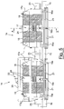
- the rigid structure 17 and the at least one floating element 18 form a sandwich structure in which the rigid structure 17 comprises two end walls 17a with respect to its longitudinal development, between which the at least one floating element 18 is interposed.
- Hooking means 19 to a pipeline 15 are envisaged in a peripheral position of the float device 14, which form a tubular seat which extends for the whole longitudinal development of the float device 14.
- Said hooking means 19 are preferably composed of a plurality of pairs of sickle-shaped arms 19a, 19b hinged to the rigid structure 17 and distributed along the whole longitudinal extension of the same 17, so as to form a tubular jaw structure.
- the opening and closing of the jaw structure 19a, 19b is piloted by means of hydraulic actuators or oil-dynamic pistons, such as for example hydraulic jacks, driven by the umbilical cable.
- the pairs of arms 19a, 19b preferably support a plurality of sliding blocks 21 having an elongated conformation and arranged parallel to each other, along the longitudinal extension of the rigid structure 17.
- the sliding surface of the sliding blocks 21 which is in contact with the pipeline 15 is preferably made of a low-friction material such as polytetrafluoroethylene (PTFE) or a wear-resistant steel.
- the float devices 14 also preferably comprise hooking means 22 to a caged transport structure 30 used for the positioning of each float device 14 hooked to the pipeline 15.
- the float devices 14 are removed, by means of the transport structure 30, from a storage base, for example situated on a supporting vessel (not illustrated), transported in correspondence with the pipeline 15 in the implementation phase and guided during the hooking phase to the pipeline 15 and to the float device 14 previously installed.
- said float devices 14 comprise at least one rigid spacing means 23 protruding from the end walls 17a of the rigid structure 17.
- At least the first float device 14 is equipped with braking means, consisting for example of a sliding block pressed onto the pipeline 15 overcoming the resistance of a spring.
- the activation of said braking means can be hydraulic.
- the activation of the braking means has the purpose for example of preventing the train of float devices 14 from coming too close to the cutting means 16 of the digging device 11.
- the float devices 14 are optionally equipped with ballasts 24 having a weight adequate for calibrating the force exerted by the float devices 14 on the pipeline 15.
- the functioning 100 of the group for laying and burying pipelines 10 is the following.
- Through the digging device 11 begins to create a trench at the sea bottom 20 in correspondence with the laying position of the pipeline 15 (phase 110).
- the first digging phase proceeds without any further interventions until the pipeline 15 is close to a "critical span" configuration, i.e. when the distance between the two rest points of the pipeline 15 is such as to create stress on the same 15 which could cause its collapse or deformation.
- a first float device 14 is taken from a storage base and transported in correspondence with the pipeline 15 (phase 120).
- the first float device 14 is then constrained to the pipeline 15 in a rear position with respect to the digging device 11 and is connected to the same 11 (phase 130). As the portion of pipeline, which is in a suspended configuration, increases as the digging proceeds, further float devices 14 are taken in succession from the storage base and transported in correspondence with the pipeline 15 (phase 140).
- the successive float devices 14 are constrained to the pipeline and connected to the float device 14 previously installed (phase 150).
- a train of float devices 14 connected to the digging device 11 and constrained to the pipeline 15 is therefore gradually created in order to sustain it in its span configuration during the digging procedure on the part of the digging device 11.
- the train of float devices 14 slides along the pipeline 15 in order to keep constant the reciprocal positioning between the digging device 11 and the first float device 14 situated in direct connection with the same 11.
- the group and method for the laying and burying of pipelines at the sea bottom therefore allow pipelines to be positioned in situ, with the subsequent and contemporaneous excavation of the sea bottom in order to bury them without them being subjected to stress due to the in span layout which is created as a result of the difference in level between the rest points of the pipeline created by the excavations. It is therefore possible to effect the excavations in a single passage or in a reduced number of passages at a great depth, thus reducing the overall implementation and burying times of the pipelines at the sea bottom.
Landscapes
- Engineering & Computer Science (AREA)
- General Engineering & Computer Science (AREA)
- Mechanical Engineering (AREA)
- Mining & Mineral Resources (AREA)
- Civil Engineering (AREA)
- Structural Engineering (AREA)
- Sewage (AREA)
- Laying Of Electric Cables Or Lines Outside (AREA)
- Electric Cable Installation (AREA)
- Artificial Fish Reefs (AREA)
- Revetment (AREA)
- Earth Drilling (AREA)
- Catching Or Destruction (AREA)
Claims (9)
- Gruppe zum Verlegen und Vergraben von Rohrleitungen am Meeresboden, wobei die Gruppe (10) eine Grabenfräse (11) umfasst, die mindestens mit Mitteln zum Einschneiden in den Meeresboden (20), Mitteln zum Absaugen und Entfernen von Sedimenten (13) und mit Mitteln zum Einhaken in eine Rohrleitung (15) und zum Gleiten darüber (15) in einer Vorschubrichtung versehen ist; und eine erste Schwimmervorrichtung (14), die eine starre Struktur (17) umfasst, die sich in Längsrichtung erstreckt, wobei die Gruppe dadurch gekennzeichnet ist, dass die erste Schwimmervorrichtung (14) mindestens ein schwimmendes Element (18) umfasst, das fest mit der starren Struktur (17) verbunden und konfiguriert ist, um an der Rohrleitung (15) befestigt zu werden, um sie in Spannweite durch die Mittel zum Einhängen in die Rohrleitung (15) zu halten, die am peripheren Abschnitt der ersten Schwimmervorrichtung (14) angeordnet sind; wobei die erste Schwimmvorrichtung direkt mit der Rückseite der Grabenfräse (11) in Bezug auf die Vorschubrichtung durch erste Verbindungsmittel (12) verbunden ist, wobei die Gruppe zweite Schwimmvorrichtungen (14) umfasst, die mit einer Schwimmvorrichtung (14) verbunden sind, die in einer Position angeordnet ist, die unmittelbar vor der Vorschubrichtung der Grabenfräse liegt, um einen Zug von Schwimmvorrichtungen (14) zu bilden.
- Die Gruppe nach Anspruch 1, worin die starre Struktur (17) und das mindestens eine schwimmende Element (18) eine Sandwichstruktur bilden, wobei die starre Struktur (17) zwei Stirnwände (17a) in Bezug auf ihre Längserstreckung umfasst, zwischen denen das mindestens eine schwimmende Element (18) angeordnet ist.
- Die Gruppe nach Anspruch 1 oder 2, worin die Einhängevorrichtung (19) eine Vielzahl von Paaren von sichelförmigen Armen (19a, 19b) umfasst, die an der starren Struktur (17) angelenkt und entlang der Längserstreckung der starren Struktur (17) verteilt sind, um eine rohrförmige Backenstruktur zu bilden.
- Die Gruppe nach Anspruch 3, umfassend eine Vielzahl von hydraulischen Stellgliedern zum Öffnen und Schließen der rohrförmigen Backenstruktur (19a, 19b).
- Die Gruppe nach Anspruch 2 oder 3, wobei das Armpaar (19a, 19b) eine Vielzahl von Gleitstücken (21) trägt, die eine längliche Konfiguration aufweisen und parallel zueinander und parallel zur Längserstreckung der starren Struktur (17) innerhalb der rohrförmigen Struktur angeordnet sind.
- Gruppe nach Anspruch 5, worin die Gleitstücke (21) eine Gleitfläche aufweisen, die zumindest teilweise aus Polytetrafluorethylen besteht.
- Die Gruppe, wie sie in einem der Ansprüche von 2 bis 6 beansprucht wird, worin die erste Schwimmervorrichtung (14) mindestens ein Abstandsmittel (23) umfasst, das von den Stirnwänden (17a) der starren Struktur (17) vorsteht.
- Die Gruppe, wie sie in einem der vorstehenden Ansprüche beansprucht wird, wobei mindestens die erste Schwimmervorrichtung (14) Bremsmittel zum Verhindern des Gleitens der ersten Schwimmervorrichtung (14) auf der Rohrleitung (15) umfasst.
- Verfahren zum Verlegen und Vergraben von Rohrleitungen auf dem Meeresboden, wobei das Verfahren (100) den Schritt umfasst von:- Ausführen einer Ausgrabung (110) im Meeresboden in einer Vortriebsrichtung entlang einer Rohrleitung (15) durch eine Grabenfräse (11), die mit einem Meeresbodenschneidemittel (16), einem Sedimentabsaugmittel und Sedimententnahmemittel (13) und mit Mitteln zum Einhaken in eine Rohrleitung (15) und zum Gleiten darüber in einer Vortriebsrichtung ausgestattet ist, wobei das Verfahren dadurch gekennzeichnet ist, dass es die folgenden Schritte umfasst:- Aufnehmen (120) einer ersten Schwimmervorrichtung (14) von einer Speicherbasis und Transportieren derselben zu der Rohrleitung (15);- Befestigen (130) der ersten Schwimmervorrichtung (14) an der Rohrleitung (15) hinter der Grabenfräse (11) in Bezug auf die Vorschubrichtung und Verbinden der Schwimmervorrichtung (14) mit der Grabenfräse (11), wenn mindestens ein Abschnitt der Rohrleitung (15) in einer schwebenden Konfiguration ist;- wenn der Abschnitt der Rohrleitung (15), der sich in schwebender Konfiguration befindet, zunimmt, Aufnehmen (140) einer zweiten Schwimmervorrichtung (14); und- Befestigen (15) der zweiten Schwimmervorrichtung (14) an der Rohrleitung (15) und Verbinden derselben (14) mit der ersten Schwimmervorrichtung (14).
Applications Claiming Priority (2)
| Application Number | Priority Date | Filing Date | Title |
|---|---|---|---|
| ITMI2009A000689A IT1393703B1 (it) | 2009-04-23 | 2009-04-23 | Gruppo e metodo di posa ed interramento di condotte a fondo mare |
| PCT/IB2010/000871 WO2010122395A1 (en) | 2009-04-23 | 2010-04-20 | Group and method for laying and burying pipelines at the seafloor |
Publications (2)
| Publication Number | Publication Date |
|---|---|
| EP2422020A1 EP2422020A1 (de) | 2012-02-29 |
| EP2422020B1 true EP2422020B1 (de) | 2019-05-22 |
Family
ID=42035803
Family Applications (1)
| Application Number | Title | Priority Date | Filing Date |
|---|---|---|---|
| EP10725366.8A Active EP2422020B1 (de) | 2009-04-23 | 2010-04-20 | Einheit und verfahren zum verlegen und vergraben von rohrleitungen auf dem meeresboden |
Country Status (8)
| Country | Link |
|---|---|
| US (1) | US8834068B2 (de) |
| EP (1) | EP2422020B1 (de) |
| CN (1) | CN102459767B (de) |
| CA (1) | CA2760054C (de) |
| EA (1) | EA022243B1 (de) |
| IT (1) | IT1393703B1 (de) |
| MY (1) | MY161216A (de) |
| WO (1) | WO2010122395A1 (de) |
Families Citing this family (22)
| Publication number | Priority date | Publication date | Assignee | Title |
|---|---|---|---|---|
| ITMI20110556A1 (it) * | 2011-04-05 | 2012-10-06 | Saipem Spa | Dispositivo spargitore di materiale inerte fluidificato per seppellire una tubazione disposta in un corpo d'acqua e metodo per spargere materiale inerte fluidificato su una tubazione disposta in un corpo d'acqua |
| ITMI20121036A1 (it) | 2012-06-14 | 2013-12-15 | Saipem Spa | Sistema e metodo di guida per varare una tubazione da un natante di posa a un letto di un corpo di acqua |
| CN103574288A (zh) * | 2012-07-19 | 2014-02-12 | 罗晓晖 | 潜艇扩环互助式水下隐布管道系统 |
| CN103123018B (zh) * | 2013-01-16 | 2013-11-20 | 中国石油大学(华东) | 犁式悬跨海底管道填埋设备 |
| CN104696588B (zh) * | 2015-03-24 | 2017-04-19 | 中国海洋石油总公司 | 深水海底管线起始铺设的方法 |
| CN104696589B (zh) * | 2015-03-24 | 2017-04-19 | 中国海洋石油总公司 | 深水海底管线终止铺设的方法 |
| TWI571582B (zh) * | 2015-06-24 | 2017-02-21 | Ian Larsen | Large diameter submerged pipe counterweight and its installation method |
| ITUB20152547A1 (it) * | 2015-07-28 | 2017-01-28 | Saipem Spa | Assieme di interramento in una trincea per una condotta continua e metodo di interramento |
| CN105485425B (zh) * | 2015-11-26 | 2019-03-22 | 天津市安维康家科技发展有限公司 | 大口径管道自动连续铺设作业机器人及其作业方法 |
| WO2017185025A1 (en) | 2016-04-21 | 2017-10-26 | Bisso Marine, LLC | Underwater pipeline burying apparatus and method |
| US10184587B1 (en) * | 2016-04-28 | 2019-01-22 | Versabar, Inc. | Underwater pipe lifting and cutting apparatus and method |
| CN107128444B (zh) * | 2017-05-15 | 2019-04-05 | 舟山万达船舶设计有限公司 | 敷缆船 |
| CN107246041B (zh) * | 2017-07-03 | 2018-07-13 | 温岭市志创网络科技有限公司 | 一种河道淤泥清除装置 |
| NL2019487B1 (en) * | 2017-09-05 | 2019-03-14 | Bluemarine Offshore Yard Service Bv | Subsea trencher and method for subsea trenching |
| EP3800297B1 (de) | 2019-10-02 | 2026-04-08 | Soil Machine Dynamics Limited | Verfahren und vorrichtung zum einbringen eines länglichen gegenstandes in einen graben in einem meeresboden |
| EP3882401B1 (de) * | 2020-03-20 | 2023-09-06 | Soil Machine Dynamics Limited | Vorrichtung und verfahren zum einbringen eines länglichen objekts in einen graben |
| CN112344096B (zh) * | 2020-11-13 | 2022-07-29 | 中船华南船舶机械有限公司 | 一种海底管道整平、铺设、锁固、埋设设备的施工方法 |
| EP4047141A1 (de) * | 2021-02-22 | 2022-08-24 | Nexans | Von oben beschickbarer kabelpflug |
| US12043979B2 (en) * | 2021-06-28 | 2024-07-23 | Soil Machine Dynamics Limited | Apparatus for inserting an elongate object into a trench |
| CN116676992A (zh) * | 2023-05-25 | 2023-09-01 | 长江生态环保集团有限公司 | 一种可在沟槽内移动的支护系统及其支护方法 |
| CN116447393B (zh) * | 2023-06-19 | 2023-09-12 | 菏泽市金沃泰化工有限公司 | 一种稳定型防脱落式管道对接装置 |
| CN117627091A (zh) * | 2023-12-22 | 2024-03-01 | 海隆石油工程(天津)有限公司 | 一种海底航道区域超深后挖沟的预备沟施工方法 |
Citations (1)
| Publication number | Priority date | Publication date | Assignee | Title |
|---|---|---|---|---|
| US4436450A (en) * | 1981-08-21 | 1984-03-13 | Exxon Production Research Co. | Apparatus and method for removing buoyancy modules from submerged pipe |
Family Cites Families (18)
| Publication number | Priority date | Publication date | Assignee | Title |
|---|---|---|---|---|
| US2731800A (en) * | 1956-01-24 | collins | ||
| US3670514A (en) * | 1970-09-04 | 1972-06-20 | Fluor Corp | Automatic submarine trencher |
| US4280289A (en) * | 1970-10-08 | 1981-07-28 | Martech International, Inc. | Underwater trenching machine for burying pipeline and the like |
| US3732701A (en) * | 1971-08-19 | 1973-05-15 | R Lynch | Underwater pipeline trenching apparatus |
| US4087981A (en) * | 1971-08-27 | 1978-05-09 | Norman Offshore Services Inc. | Buoyant self-propelled underwater trenching apparatus |
| US4149326A (en) * | 1975-02-11 | 1979-04-17 | Saipem S.P.A. | Machine for digging a trench beneath a submerged pipeline |
| NL7511638A (nl) * | 1975-10-03 | 1977-04-05 | Johannes Franciscus Oosterkamp | Werkwijze voor het installeren van pijpleidingen op zeer grote waterdiepte, en inrichting voor het uitvoeren van deze werkwijze. |
| US4314414A (en) * | 1978-11-29 | 1982-02-09 | Land And Marine Engineering Limited | Trench digging apparatus and bearing therefor |
| IT1109854B (it) * | 1979-01-08 | 1985-12-23 | Saipem Spa | Metodo per riparare una tubazione danneggiata posata su alti fondali del mare ed apparecchiature per la sua realizzazione |
| DE3045901A1 (de) * | 1980-12-05 | 1982-07-08 | Schüttgutfördertechnik AG, 9009 St. Gallen | Vorrichtung zum foerdern von unter wasser lagerndem schuettgut |
| US4395158A (en) * | 1981-01-22 | 1983-07-26 | Brooks Jerry A | Method and apparatus for entrenching an enlongated under-water structure |
| US4516880A (en) * | 1982-04-19 | 1985-05-14 | Martin Charles F | Underwater trenching apparatus |
| US4586850A (en) * | 1983-07-12 | 1986-05-06 | Norman Robert M | Underwater trenching system |
| US6196766B1 (en) * | 1994-10-07 | 2001-03-06 | Neil Deryck Bray Graham | Apparatus for movement along an underground passage and method using same |
| GB0123658D0 (en) * | 2001-10-02 | 2001-11-21 | Global Marine Systems Ltd | Cable or pipe retrieval and burial apparatus and methods |
| JP4121305B2 (ja) * | 2002-05-16 | 2008-07-23 | 新日鉄エンジニアリング株式会社 | 水底地盤掘削用プラウとこのプラウを用いた水底管体敷設工法 |
| US6821054B2 (en) * | 2002-08-19 | 2004-11-23 | Horizon Vessels, Inc. | Method and system for laying pipe through the use of a plow |
| GB0708082D0 (en) * | 2007-04-26 | 2007-06-06 | Soil Machine Dynamics Ltd | Vehicle for laying an elongated product in a trench in the sea floor |
-
2009
- 2009-04-23 IT ITMI2009A000689A patent/IT1393703B1/it active
-
2010
- 2010-04-20 MY MYPI2011005106A patent/MY161216A/en unknown
- 2010-04-20 US US13/265,403 patent/US8834068B2/en active Active
- 2010-04-20 EA EA201190233A patent/EA022243B1/ru active IP Right Revival
- 2010-04-20 WO PCT/IB2010/000871 patent/WO2010122395A1/en not_active Ceased
- 2010-04-20 CN CN201080025097.1A patent/CN102459767B/zh active Active
- 2010-04-20 CA CA2760054A patent/CA2760054C/en active Active
- 2010-04-20 EP EP10725366.8A patent/EP2422020B1/de active Active
Patent Citations (1)
| Publication number | Priority date | Publication date | Assignee | Title |
|---|---|---|---|---|
| US4436450A (en) * | 1981-08-21 | 1984-03-13 | Exxon Production Research Co. | Apparatus and method for removing buoyancy modules from submerged pipe |
Also Published As
| Publication number | Publication date |
|---|---|
| WO2010122395A1 (en) | 2010-10-28 |
| IT1393703B1 (it) | 2012-05-08 |
| ITMI20090689A1 (it) | 2010-10-24 |
| CA2760054C (en) | 2017-06-20 |
| US20120114420A1 (en) | 2012-05-10 |
| EP2422020A1 (de) | 2012-02-29 |
| CN102459767B (zh) | 2015-05-27 |
| MY161216A (en) | 2017-04-14 |
| EA201190233A1 (ru) | 2012-04-30 |
| CN102459767A (zh) | 2012-05-16 |
| EA022243B1 (ru) | 2015-11-30 |
| US8834068B2 (en) | 2014-09-16 |
| CA2760054A1 (en) | 2010-10-28 |
Similar Documents
| Publication | Publication Date | Title |
|---|---|---|
| EP2422020B1 (de) | Einheit und verfahren zum verlegen und vergraben von rohrleitungen auf dem meeresboden | |
| US5044827A (en) | Method for recovering wet buckled pipe | |
| US7520696B2 (en) | Vehicle for installing a cable in a ground formation | |
| EP2331754B1 (de) | Verfahren und system zum unterirdischen verlegen eines durchgehenden, länglichen glieds in einem bett eines gewässers | |
| EP2511996B1 (de) | Unterwasserkabelinstallationseinheit | |
| EP2534400B1 (de) | Verfahren zur verlegung einer hybridrohrleitung auf dem meeresboden | |
| US9834907B1 (en) | System and method of concurrently trenching, laying and burying underwater pipeline | |
| JP2003529689A (ja) | 海中浚渫方法及び装置 | |
| US4041719A (en) | Method and apparatus for connecting submarine pipelines | |
| US8425154B1 (en) | System and method for repairing and extended length of a subsea pipeline | |
| EP1022501A1 (de) | Verfahren und Vorrichtung zum Verlegen einer Meerespipeline | |
| KR101873537B1 (ko) | 해저 파이프라인 부설 장치 | |
| EP3347530B1 (de) | Verfahren und system zum vergraben einer rohrleitung in einem gewässergrund | |
| WO2007127684A2 (en) | Towing and installation method for deepwater pipelines and risers | |
| US11578817B2 (en) | Method and system for laying a pipeline on the bed of a body of water | |
| US11884368B2 (en) | Launching elongate subsea structures | |
| NO171578B (no) | Fremgangsmaate og anordning for samtidig groefting og roerlegging i arktiske stroek | |
| KR20130003925A (ko) | 리프팅 지그를 이용한 해저 파이프 라인의 스트립 교체 방법 | |
| OA20132A (en) | Method and system for laying a pipeline on the bed of a body of water. | |
| KR20150003767U (ko) | 해저 파이프와 해저 케이블 설치 시 안전 간격 유지 장비 | |
| JP2000297881A (ja) | 管路の水底部設置治具及び管路の水底部設置方法 | |
| JP2000297880A (ja) | 管路を用いた取水方法 |
Legal Events
| Date | Code | Title | Description |
|---|---|---|---|
| PUAI | Public reference made under article 153(3) epc to a published international application that has entered the european phase |
Free format text: ORIGINAL CODE: 0009012 |
|
| 17P | Request for examination filed |
Effective date: 20111021 |
|
| AK | Designated contracting states |
Kind code of ref document: A1 Designated state(s): AT BE BG CH CY CZ DE DK EE ES FI FR GB GR HR HU IE IS IT LI LT LU LV MC MK MT NL NO PL PT RO SE SI SK SM TR |
|
| DAX | Request for extension of the european patent (deleted) | ||
| 17Q | First examination report despatched |
Effective date: 20130411 |
|
| STAA | Information on the status of an ep patent application or granted ep patent |
Free format text: STATUS: EXAMINATION IS IN PROGRESS |
|
| GRAP | Despatch of communication of intention to grant a patent |
Free format text: ORIGINAL CODE: EPIDOSNIGR1 |
|
| STAA | Information on the status of an ep patent application or granted ep patent |
Free format text: STATUS: GRANT OF PATENT IS INTENDED |
|
| INTG | Intention to grant announced |
Effective date: 20181207 |
|
| GRAS | Grant fee paid |
Free format text: ORIGINAL CODE: EPIDOSNIGR3 |
|
| GRAA | (expected) grant |
Free format text: ORIGINAL CODE: 0009210 |
|
| STAA | Information on the status of an ep patent application or granted ep patent |
Free format text: STATUS: THE PATENT HAS BEEN GRANTED |
|
| AK | Designated contracting states |
Kind code of ref document: B1 Designated state(s): AT BE BG CH CY CZ DE DK EE ES FI FR GB GR HR HU IE IS IT LI LT LU LV MC MK MT NL NO PL PT RO SE SI SK SM TR |
|
| REG | Reference to a national code |
Ref country code: GB Ref legal event code: FG4D |
|
| REG | Reference to a national code |
Ref country code: CH Ref legal event code: EP |
|
| REG | Reference to a national code |
Ref country code: IE Ref legal event code: FG4D |
|
| REG | Reference to a national code |
Ref country code: DE Ref legal event code: R096 Ref document number: 602010059032 Country of ref document: DE |
|
| REG | Reference to a national code |
Ref country code: AT Ref legal event code: REF Ref document number: 1136272 Country of ref document: AT Kind code of ref document: T Effective date: 20190615 |
|
| REG | Reference to a national code |
Ref country code: NL Ref legal event code: FP |
|
| REG | Reference to a national code |
Ref country code: LT Ref legal event code: MG4D |
|
| PG25 | Lapsed in a contracting state [announced via postgrant information from national office to epo] |
Ref country code: LT Free format text: LAPSE BECAUSE OF FAILURE TO SUBMIT A TRANSLATION OF THE DESCRIPTION OR TO PAY THE FEE WITHIN THE PRESCRIBED TIME-LIMIT Effective date: 20190522 Ref country code: HR Free format text: LAPSE BECAUSE OF FAILURE TO SUBMIT A TRANSLATION OF THE DESCRIPTION OR TO PAY THE FEE WITHIN THE PRESCRIBED TIME-LIMIT Effective date: 20190522 Ref country code: FI Free format text: LAPSE BECAUSE OF FAILURE TO SUBMIT A TRANSLATION OF THE DESCRIPTION OR TO PAY THE FEE WITHIN THE PRESCRIBED TIME-LIMIT Effective date: 20190522 Ref country code: NO Free format text: LAPSE BECAUSE OF FAILURE TO SUBMIT A TRANSLATION OF THE DESCRIPTION OR TO PAY THE FEE WITHIN THE PRESCRIBED TIME-LIMIT Effective date: 20190822 Ref country code: PT Free format text: LAPSE BECAUSE OF FAILURE TO SUBMIT A TRANSLATION OF THE DESCRIPTION OR TO PAY THE FEE WITHIN THE PRESCRIBED TIME-LIMIT Effective date: 20190922 Ref country code: SE Free format text: LAPSE BECAUSE OF FAILURE TO SUBMIT A TRANSLATION OF THE DESCRIPTION OR TO PAY THE FEE WITHIN THE PRESCRIBED TIME-LIMIT Effective date: 20190522 Ref country code: ES Free format text: LAPSE BECAUSE OF FAILURE TO SUBMIT A TRANSLATION OF THE DESCRIPTION OR TO PAY THE FEE WITHIN THE PRESCRIBED TIME-LIMIT Effective date: 20190522 |
|
| PG25 | Lapsed in a contracting state [announced via postgrant information from national office to epo] |
Ref country code: BG Free format text: LAPSE BECAUSE OF FAILURE TO SUBMIT A TRANSLATION OF THE DESCRIPTION OR TO PAY THE FEE WITHIN THE PRESCRIBED TIME-LIMIT Effective date: 20190822 Ref country code: LV Free format text: LAPSE BECAUSE OF FAILURE TO SUBMIT A TRANSLATION OF THE DESCRIPTION OR TO PAY THE FEE WITHIN THE PRESCRIBED TIME-LIMIT Effective date: 20190522 Ref country code: GR Free format text: LAPSE BECAUSE OF FAILURE TO SUBMIT A TRANSLATION OF THE DESCRIPTION OR TO PAY THE FEE WITHIN THE PRESCRIBED TIME-LIMIT Effective date: 20190823 |
|
| REG | Reference to a national code |
Ref country code: AT Ref legal event code: MK05 Ref document number: 1136272 Country of ref document: AT Kind code of ref document: T Effective date: 20190522 |
|
| PG25 | Lapsed in a contracting state [announced via postgrant information from national office to epo] |
Ref country code: EE Free format text: LAPSE BECAUSE OF FAILURE TO SUBMIT A TRANSLATION OF THE DESCRIPTION OR TO PAY THE FEE WITHIN THE PRESCRIBED TIME-LIMIT Effective date: 20190522 Ref country code: SK Free format text: LAPSE BECAUSE OF FAILURE TO SUBMIT A TRANSLATION OF THE DESCRIPTION OR TO PAY THE FEE WITHIN THE PRESCRIBED TIME-LIMIT Effective date: 20190522 Ref country code: AT Free format text: LAPSE BECAUSE OF FAILURE TO SUBMIT A TRANSLATION OF THE DESCRIPTION OR TO PAY THE FEE WITHIN THE PRESCRIBED TIME-LIMIT Effective date: 20190522 Ref country code: DK Free format text: LAPSE BECAUSE OF FAILURE TO SUBMIT A TRANSLATION OF THE DESCRIPTION OR TO PAY THE FEE WITHIN THE PRESCRIBED TIME-LIMIT Effective date: 20190522 Ref country code: RO Free format text: LAPSE BECAUSE OF FAILURE TO SUBMIT A TRANSLATION OF THE DESCRIPTION OR TO PAY THE FEE WITHIN THE PRESCRIBED TIME-LIMIT Effective date: 20190522 Ref country code: CZ Free format text: LAPSE BECAUSE OF FAILURE TO SUBMIT A TRANSLATION OF THE DESCRIPTION OR TO PAY THE FEE WITHIN THE PRESCRIBED TIME-LIMIT Effective date: 20190522 |
|
| REG | Reference to a national code |
Ref country code: DE Ref legal event code: R097 Ref document number: 602010059032 Country of ref document: DE |
|
| PG25 | Lapsed in a contracting state [announced via postgrant information from national office to epo] |
Ref country code: SM Free format text: LAPSE BECAUSE OF FAILURE TO SUBMIT A TRANSLATION OF THE DESCRIPTION OR TO PAY THE FEE WITHIN THE PRESCRIBED TIME-LIMIT Effective date: 20190522 |
|
| PLBE | No opposition filed within time limit |
Free format text: ORIGINAL CODE: 0009261 |
|
| STAA | Information on the status of an ep patent application or granted ep patent |
Free format text: STATUS: NO OPPOSITION FILED WITHIN TIME LIMIT |
|
| PG25 | Lapsed in a contracting state [announced via postgrant information from national office to epo] |
Ref country code: TR Free format text: LAPSE BECAUSE OF FAILURE TO SUBMIT A TRANSLATION OF THE DESCRIPTION OR TO PAY THE FEE WITHIN THE PRESCRIBED TIME-LIMIT Effective date: 20190522 |
|
| 26N | No opposition filed |
Effective date: 20200225 |
|
| PG25 | Lapsed in a contracting state [announced via postgrant information from national office to epo] |
Ref country code: PL Free format text: LAPSE BECAUSE OF FAILURE TO SUBMIT A TRANSLATION OF THE DESCRIPTION OR TO PAY THE FEE WITHIN THE PRESCRIBED TIME-LIMIT Effective date: 20190522 |
|
| PG25 | Lapsed in a contracting state [announced via postgrant information from national office to epo] |
Ref country code: SI Free format text: LAPSE BECAUSE OF FAILURE TO SUBMIT A TRANSLATION OF THE DESCRIPTION OR TO PAY THE FEE WITHIN THE PRESCRIBED TIME-LIMIT Effective date: 20190522 |
|
| REG | Reference to a national code |
Ref country code: DE Ref legal event code: R119 Ref document number: 602010059032 Country of ref document: DE |
|
| PG25 | Lapsed in a contracting state [announced via postgrant information from national office to epo] |
Ref country code: MC Free format text: LAPSE BECAUSE OF FAILURE TO SUBMIT A TRANSLATION OF THE DESCRIPTION OR TO PAY THE FEE WITHIN THE PRESCRIBED TIME-LIMIT Effective date: 20190522 |
|
| REG | Reference to a national code |
Ref country code: CH Ref legal event code: PL |
|
| PG25 | Lapsed in a contracting state [announced via postgrant information from national office to epo] |
Ref country code: DE Free format text: LAPSE BECAUSE OF NON-PAYMENT OF DUE FEES Effective date: 20201103 Ref country code: LI Free format text: LAPSE BECAUSE OF NON-PAYMENT OF DUE FEES Effective date: 20200430 Ref country code: LU Free format text: LAPSE BECAUSE OF NON-PAYMENT OF DUE FEES Effective date: 20200420 Ref country code: CH Free format text: LAPSE BECAUSE OF NON-PAYMENT OF DUE FEES Effective date: 20200430 |
|
| REG | Reference to a national code |
Ref country code: BE Ref legal event code: MM Effective date: 20200430 |
|
| PG25 | Lapsed in a contracting state [announced via postgrant information from national office to epo] |
Ref country code: BE Free format text: LAPSE BECAUSE OF NON-PAYMENT OF DUE FEES Effective date: 20200430 |
|
| PG25 | Lapsed in a contracting state [announced via postgrant information from national office to epo] |
Ref country code: IE Free format text: LAPSE BECAUSE OF NON-PAYMENT OF DUE FEES Effective date: 20200420 |
|
| PG25 | Lapsed in a contracting state [announced via postgrant information from national office to epo] |
Ref country code: MT Free format text: LAPSE BECAUSE OF FAILURE TO SUBMIT A TRANSLATION OF THE DESCRIPTION OR TO PAY THE FEE WITHIN THE PRESCRIBED TIME-LIMIT Effective date: 20190522 Ref country code: CY Free format text: LAPSE BECAUSE OF FAILURE TO SUBMIT A TRANSLATION OF THE DESCRIPTION OR TO PAY THE FEE WITHIN THE PRESCRIBED TIME-LIMIT Effective date: 20190522 |
|
| PG25 | Lapsed in a contracting state [announced via postgrant information from national office to epo] |
Ref country code: MK Free format text: LAPSE BECAUSE OF FAILURE TO SUBMIT A TRANSLATION OF THE DESCRIPTION OR TO PAY THE FEE WITHIN THE PRESCRIBED TIME-LIMIT Effective date: 20190522 Ref country code: IS Free format text: LAPSE BECAUSE OF FAILURE TO SUBMIT A TRANSLATION OF THE DESCRIPTION OR TO PAY THE FEE WITHIN THE PRESCRIBED TIME-LIMIT Effective date: 20190922 |
|
| P01 | Opt-out of the competence of the unified patent court (upc) registered |
Effective date: 20230420 |
|
| P02 | Opt-out of the competence of the unified patent court (upc) changed |
Effective date: 20231116 |
|
| PGFP | Annual fee paid to national office [announced via postgrant information from national office to epo] |
Ref country code: NL Payment date: 20250424 Year of fee payment: 16 |
|
| PGFP | Annual fee paid to national office [announced via postgrant information from national office to epo] |
Ref country code: GB Payment date: 20250422 Year of fee payment: 16 |
|
| PGFP | Annual fee paid to national office [announced via postgrant information from national office to epo] |
Ref country code: IT Payment date: 20250422 Year of fee payment: 16 |
|
| PGFP | Annual fee paid to national office [announced via postgrant information from national office to epo] |
Ref country code: FR Payment date: 20250424 Year of fee payment: 16 |