EP2420425A1 - Wagenkasten für Schienenfahrzeuge - Google Patents
Wagenkasten für Schienenfahrzeuge Download PDFInfo
- Publication number
- EP2420425A1 EP2420425A1 EP11176914A EP11176914A EP2420425A1 EP 2420425 A1 EP2420425 A1 EP 2420425A1 EP 11176914 A EP11176914 A EP 11176914A EP 11176914 A EP11176914 A EP 11176914A EP 2420425 A1 EP2420425 A1 EP 2420425A1
- Authority
- EP
- European Patent Office
- Prior art keywords
- flow
- segment
- car body
- body according
- end cap
- Prior art date
- Legal status (The legal status is an assumption and is not a legal conclusion. Google has not performed a legal analysis and makes no representation as to the accuracy of the status listed.)
- Granted
Links
Images




Classifications
-
- B—PERFORMING OPERATIONS; TRANSPORTING
- B61—RAILWAYS
- B61D—BODY DETAILS OR KINDS OF RAILWAY VEHICLES
- B61D17/00—Construction details of vehicle bodies
- B61D17/04—Construction details of vehicle bodies with bodies of metal; with composite, e.g. metal and wood body structures
- B61D17/06—End walls
-
- B—PERFORMING OPERATIONS; TRANSPORTING
- B60—VEHICLES IN GENERAL
- B60T—VEHICLE BRAKE CONTROL SYSTEMS OR PARTS THEREOF; BRAKE CONTROL SYSTEMS OR PARTS THEREOF, IN GENERAL; ARRANGEMENT OF BRAKING ELEMENTS ON VEHICLES IN GENERAL; PORTABLE DEVICES FOR PREVENTING UNWANTED MOVEMENT OF VEHICLES; VEHICLE MODIFICATIONS TO FACILITATE COOLING OF BRAKES
- B60T1/00—Arrangements of braking elements, i.e. of those parts where braking effect occurs specially for vehicles
- B60T1/12—Arrangements of braking elements, i.e. of those parts where braking effect occurs specially for vehicles acting otherwise than by retarding wheels, e.g. jet action
- B60T1/16—Arrangements of braking elements, i.e. of those parts where braking effect occurs specially for vehicles acting otherwise than by retarding wheels, e.g. jet action by increasing air resistance, e.g. flaps
-
- B—PERFORMING OPERATIONS; TRANSPORTING
- B61—RAILWAYS
- B61H—BRAKES OR OTHER RETARDING DEVICES SPECIALLY ADAPTED FOR RAIL VEHICLES; ARRANGEMENT OR DISPOSITION THEREOF IN RAIL VEHICLES
- B61H11/00—Applications or arrangements of braking or retarding apparatus not otherwise provided for; Combinations of apparatus of different kinds or types
- B61H11/06—Applications or arrangements of braking or retarding apparatus not otherwise provided for; Combinations of apparatus of different kinds or types of hydrostatic, hydrodynamic, or aerodynamic brakes
- B61H11/10—Aerodynamic brakes with control flaps, e.g. spoilers, attached to the vehicles
Definitions
- the invention relates to a rail car body comprising a main segment and an end segment tapering from the main segment opposite to a direction of travel from a full cross-sectional area of the main segment to an end segment.
- the invention is therefore an object of the invention to improve the braking possibilities for a car body of the generic type.
- the end segment comprises at least one flow obstruction element, which in an active, the outer flows of the end segment to the braking effect hindering position can be brought from an inactive, outer flows of the end segment smoothly permitting position.
- the at least one flow-inhibiting element is formed by a portion of the end segment which is movable in a movement from the inactive position to the active position opposite to the direction of travel.
- a particularly favorable solution provides that the at least one flow-inhibiting element is formed by an end cap of the end segment, which can be lifted in a movement from the inactive to the active position of the adjoining the main segment Endsegmentstumpf the end segment opposite to the direction of travel.
- An advantageous embodiment provides that the end cap has a flowed in the active position wall, which is not in the inactive position of the end cap of the end portion flowing around the outer flow can not be flowed.
- another advantageous solution provides that the at least one flow-inhibiting element is arranged in its inactive position within the outer contour of the end segment and protrudes outwards in its active position beyond the outer contour of the end segment.
- Such a flow-inhibiting element is also advantageous in the sense of the invention in order to obstruct the external flow as far as possible over the region of the end segment.
- a particularly favorable solution provides that in the active position the flow-preventing element projects like an umbrella over the outer contour of the end segment.
- the end segment is provided with openings from which the umbrella-like flow obstruction element is extendable.
- the at least one flow-inhibiting element can be extended out of the end cap.
- a particularly favorable solution which in particular generates a very large braking force, provides that the at least one flow-obstructing element deflects an outer flow flowing around the end segment in its flow direction by at least 90 °.
- the channel is formed by a flow guide element and a wall of the end cap, so that the counterflow can be targeted.
- the channel can escape the counterflow so that it is directed opposite to an outer flow surrounding the end segment.
- An embodiment of an in Fig. 1 partially illustrated car body 10 comprises a main segment 12 and an opposite to a direction of travel 14 to the main segment 12 subsequent end segment 16, which has a starting from an outer contour 20 of the main segment to a tapered outer contour 24 to 24, wherein in the region Outer contour 20 of the main segment 12, the cross-sectional area QH is present, which decreases with increasing course of the outer contour 24 of the end segment opposite to the direction of travel 40 increasingly up to the outer contour QE at the end 22 or tapered.
- the end segment 16 in this case comprises an end cap 30 which extends from the end 22 in the direction of travel 14 and which can be separated by a dividing line 32 from the end segment stub 36 of the end segment 16 lying between the end cap 30 and the main segment 12.
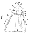
- the end cap 30 is as in FIG Fig. 2 shown at the first, in Fig. 1 and 2 illustrated embodiment opposite to the direction of travel 14 relative to Endsegmentstumpf 36 slidably so that between the Endsegmentstumpf 36 and the end cap 30, a free space 40 is formed over which meet the tapered outer contour 24 along the outer flows 42 on an outer wall 46 of the end cap 30, this in an inner space 44 of the end cap 30 deflects, which acts as a storage space for the outer flows 42 and the accumulating outer flows 42 can exit via an end opening 48 of the end cap 30.
- the end cap 30 For transmitting the braking forces from the end cap 30 to the carbody 10, the end cap 30 is positioned on the end segment stump 36 between the inactive position, shown in FIG. 3, via a plurality of guide means 50 extending in a direction of movement B of the end cap 30 relative to the end segment stump 36 Fig. 1 , and the active position, shown in Fig. 2 , movably guided and fixable both in the inactive position and in the active position.
- the end cap is arranged such that at least upper outer flows 42o and lateral outer flows 42s enter and accumulate in the inner space 44 of the end cap, for example, lower outer flows for the braking action of the end cap 30 may be neglected.
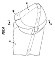
- the nose cap 30 is movable in the same way and with the same guide means 50 from the inactive position to the active position relative to Endsegmentstumpf 36, but with the difference that in the end cap 30 umbrella-like deployable air guide elements 60 are provided which the deflection of the outer flows 42o and 42s into the inner space 44 of the end cap 30 still improve, in the active position in the widest possible extent Ninströmungen 42 into the interior 44 of the end cap 30 lead.
- lateral flow guide elements 62 and an end-side flow guide element 64 are provided, which deflect the entering into the interior 44 outer flows 42 in the outer flows 42 counterflow 72 counterflowing in a channel 74 between the inner flow guide elements 62 and a Outer wall 66 of the end cap 30 extend and pass through an intermediate space 68 between the outer walls 66 of the end cap 30 and the Strömungsumschettin 60 outwardly to on a side facing away from the Endstumstumpf 36 side of the interior 44 entering the outer flows 42 to be able to flow against them, thus to obtain an optimal braking effect by the end cap 30 in the active position.
Landscapes
- Engineering & Computer Science (AREA)
- Mechanical Engineering (AREA)
- Physics & Mathematics (AREA)
- Fluid Mechanics (AREA)
- Life Sciences & Earth Sciences (AREA)
- Wood Science & Technology (AREA)
- Transportation (AREA)
- Platform Screen Doors And Railroad Systems (AREA)
Abstract
Description
- Die Erfindung betrifft einen Wagenkasten für Schienenfahrzeuge, umfassend ein Hauptsegment und ein sich ausgehend von dem Hauptsegment entgegengesetzt zu einer Fahrtrichtung von einer vollen Querschnittsfläche des Hauptsegments zu einem Ende verjüngendes Endsegment.
- Derartige Wagenkästen sind bei heutigen Hochgeschwindigkeitszügen bekannt.
- Bei den heutigen Hochgeschwindigkeitszügen besteht allerdings das Problem, dass eine Bremsung lediglich über die Wechselwirkung zwischen Rad und Schiene und/oder über Magnet- oder Wirbelstrombremsen möglich ist, wobei die Wechselwirkung zwischen Rad und Schiene aufgrund der bestehenden Reibungsverhältnisse nur in begrenztem Umfang Bremskräfte aufnehmen kann.
- Der Erfindung liegt daher die Aufgabe zugrunde, die Bremsmöglichkeiten für einen Wagenkasten der gattungsgemäßen Art zu verbessern.
- Diese Aufgabe wird bei einem Wagenkasten für Schienenfahrzeuge der eingangs beschriebenen Art erfindungsgemäß dadurch gelöst, dass das Endsegment mindestens ein Strömungshinderungselement umfasst, welches von einer inaktiven, Außenströmungen des Endsegments störungsfrei zulassenden Stellung in eine aktive, die Außenströmungen des Endsegments zur Bremswirkung hindernden Stellung bringbar ist.
- Der Vorteil der erfindungsgemäßen Lösung ist darin zu sehen, dass durch das mindestens eine Strömungshinderungselement eine Möglichkeit geschaffen wird, eine zusätzliche Bremsung des Wagenkastens zu bewirken, ohne dass eine weitere Belastung der Wechselwirkung zwischen Rad und Schiene erforderlich ist.
- Besonders günstig ist es dabei, wenn das mindestens eine Strömungshinderungselement durch einen Abschnitt des Endsegments gebildet ist, welcher bei einer Bewegung von der inaktiven Stellung in die aktive Stellung entgegengesetzt zur Fahrtrichtung bewegbar ist.
- Damit besteht in einfacher Weise die Möglichkeit, die Außenströmungen zu behindern und somit die Bremswirkung zu erzeugen.
- Eine besonders günstige Lösung sieht vor, dass das mindestens eine Strömungshinderungselement durch eine Endkappe des Endsegments gebildet ist, welche bei einer Bewegung von der inaktiven in die aktive Stellung von dem sich an das Hauptsegment anschließenden Endsegmentstumpf des Endsegments entgegengesetzt zur Fahrtrichtung abhebbar ist.
- Eine derartige Lösung ist besonders einfache zu realisieren, da damit die Endkappe als Ganzes von dem Endsegmentstumpf abgehoben werden kann, um die Außenströmung zu behindern.
- Eine vorteilhafte Ausführungsform sieht vor, dass die Endkappe eine in der aktiven Stellung angeströmte Wand aufweist, die in der inaktiven Stellung der Endkappe von der den Endabschnitt umströmenden Außenströmung nicht anströmbar ist.
- Alternativ oder ergänzend zum Vorsehen einer Endkappe sieht eine andere vorteilhafte Lösung vor, dass das mindestens eine Strömungshinderungselement in seiner inaktiven Stellung innerhalb der Außenkontur des Endsegments angeordnet ist und in seiner aktiven Stellung über die Außenkontur des Endsegments nach außen übersteht.
- Ein derartiges Strömungshinderungselement ist ebenfalls im Sinne der Erfindung vorteilhaft, um die Außenströmung um Bereich des Endsegments möglichst stark zu behindern.
- Eine besonders günstige Lösung sieht vor, dass das Strömungshinderungselement in der aktiven Stellung schirmartig über die Außenkontur des Endsegments übersteht.
- Dabei bestehen unterschiedliche Möglichkeiten, das schirmartige Strömungshinderungselement in seine aktive Stellung zu bringen.
- Eine vorteilhafte Lösung sieht vor, dass das schirmartige Strömungshinderungselement aus dem Endsegment 16 ausfahrbar ist.
- Das heißt, dass beispielsweise in diesem Fall das Endsegment mit Öffnungen versehen ist, aus denen das schirmartige Strömungshinderungselement ausfahrbar ist.
- Insbesondere in Verbindung mit einer Endkappe des Endsegments ist es besonders günstig, wenn das mindestens eine Strömungshinderungselement aus der Endkappe ausfahrbar ist.
- Eine besonders günstige Lösung, die insbesondere eine sehr große Bremskraft erzeugt, sieht vor, dass das mindestens eine Strömungshinderungselement eine das Endsegment umströmende Außenströmung in ihrer Strömungsrichtung um mindestens 90° umlenkt.
- Eine derartige starke Umlenkung der Außenströmung ermöglicht es, eine sehr gute Bremswirkung zu erzielen.
- Eine noch vorteilhaftere Bremswirkung lässt sich dann erzielen, wenn die an der Außenkontur des Endbereichs entlanglaufenden Außenströmung in der aktiven Stellung der Endkappe in einem Innenraum der Endkappe eine Umlenkung erfährt und aus einem Kanal als Gegenströmung austritt.
- Eine derartige Lösung ermöglicht eine besonders hohe und effiziente Bremswirkung für das Schienenfahrzeug.
- Besonders günstig ist es dabei, wenn der Kanal durch ein Strömungsführungselement und eine Wand der Endkappe gebildet ist, so dass sich die Gegenströmung gezielt ausrichten lässt.
- Dabei ist es besonders günstig, wenn der Kanal die Gegenströmung so austreten lässt, dass diese einer das Endsegment umgebenden Außenströmung entgegengesetzt gerichtet ist.
- Weitere Merkmale und Vorteile der Erfindung sind Gegenstand der nachfolgenden Beschreibung sowie der zeichnerischen Darstellung einiger Ausführungsbeispiele.
- In der Zeichnung zeigen:
- Fig. 1
- eine abschnittsweise Darstellung eines erfindungsgemäßen Wagenkastens gemäß einem ersten Ausführungsbeispiel bei in einer inaktiven Stellung stehendem Strömungshinderungselement in Form einer Endkappe;
- Fig. 2
- eine Darstellung ähnlich
Fig. 1 des ersten Ausführungsbeispiels bei in der aktiven Stellung stehendem Strömungshinderungselement in Form der Endkappe; - Fig. 3
- eine Darstellung ähnlich
Fig. 2 eines zweiten Ausführungsbeispiels eines erfindungsgemäßen Wagenkastens bei in einer aktiven Stellung stehenden Strömungshinderungselementen in Form einer Endkappe und schirmartigen Luftleitelementen; - Fig. 4
- eine perspektivische Darstellung der Strömungshinderungselemente des zweiten Ausführungsbeispiels mit Draufsicht von hinten;
- Fig. 5
- eine seitliche Darstellung des zweiten Ausführungsbeispiels bei in der aktiven Stellung stehenden Strömungshinderungselementen und
- Fig. 6
- einen Schnitt längs Linie 6-6 in
Fig. 4 . - Ein Ausführungsbeispiel eines in
Fig. 1 teilweise dargestellten Wagenkastens 10 umfasst ein Hauptsegment 12 sowie ein sich entgegengesetzt zu einer Fahrtrichtung 14 an das Hauptsegment 12 anschließendes Endsegment 16, welches eine sich ausgehend von einer Außenkontur 20 des Hauptsegments eine sich bis zu einem Ende 22 verjüngende Außenkontur 24 aufweist, wobei im Bereich der Außenkontur 20 des Hauptsegments 12 die Querschnittsfläche QH vorliegt, die sich mit zunehmendem Verlauf der Außenkontur 24 des Endsegments entgegengesetzt zur Fahrtrichtung 40 zunehmend bis zur Außenkontur QE am Ende 22 verringert oder verjüngt. - Die sich von der Außenkontur 20 bis zum Ende 22 zunehmend verjüngende Außenkontur 24 führt dabei zu einem Luftwiderstand des Endsegments 16 (CW-Wert) in der Größenordnung von < 0,2. Das Endsegment 16 umfasst dabei eine sich ausgehend vom Ende 22 in der Fahrtrichtung 14 erstreckende Endkappe 30, welche durch eine Trennlinie 32 von dem zwischen der Endkappe 30 und dem Hauptsegment 12 liegenden Endsegmentstumpf 36 des Endsegments 16 abtrennbar ist.
- Die Endkappe 30 ist, wie in
Fig. 2 dargestellt, bei dem ersten, inFig. 1 und2 dargestellten Ausführungsbeispiel entgegengesetzt zur Fahrtrichtung 14 relativ zum Endsegmentstumpf 36 verschiebbar, so dass zwischen dem Endsegmentstumpf 36 und der Endkappe 30 ein Freiraum 40 entsteht, über welchen an der sich verjüngenden Außenkontur 24 entlanglaufende Außenströmungen 42 auf eine Außenwand 46 der Endkappe 30 treffen, die diese in einen Innenraum 44 der Endkappe 30 umlenkt, welcher als Stauraum für die Außenströmungen 42 wirkt und die sich aufstauenden Außenströmungen 42 über eine Endöffnung 48 der Endkappe 30 austreten lässt. - Dadurch, dass die Endkappe 30 in der in
Fig. 2 dargestellten aktiven Stellung die ausgehend vom Hauptsegment 12 längs des Endsegments 16 verlaufenden Außenströmungen 42 zumindest zum Teil in ihrem Innenraum 44 aufstaut und über die Endöffnung 48 abströmen lässt, erzeugt die Endkappe 30 eine entgegengesetzt zur Fahrtrichtung 14 gerichtete aerodynamische Bremswirkung auf den Wagenkasten 10. - Zur Übertragung der Bremskräfte von der Endkappe 30 auf den Wagenkasten 10 ist die Endkappe 30 über mehrere sich in einer Bewegungsrichtung B der Endkappe 30 relativ zum Endsegmentstumpf 36 erstreckende Führungseinrichtungen 50 an dem Endsegmentstumpf 36 zwischen der inaktiven Stellung, dargestellt in
Fig. 1 , und der aktiven Stellung, dargestellt inFig. 2 , bewegbar geführt und sowohl in der inaktiven Stellung als auch in der aktiven Stellung fixierbar. - In der aktiven Stellung, dargestellt in
Fig. 2 , ist die Endkappe beispielsweise derart angeordnet, dass zumindest obere Außenströmungen 42o und seitliche Außenströmungen 42s in den Innenraum 44 der Endkappe eintreten und gestaut werden, wobei beispielsweise untere Außenströmungen für die Bremswirkung der Endkappe 30 vernachlässigt werden können. - Bei einem zweiten Ausführungsbeispiel, dargestellt in den
Figuren 3 bis 6 , ist die Nasenkappe 30 in gleicher Weise und mit denselben Führungseinrichtungen 50 von der inaktiven Stellung in die aktive Stellung relativ zum Endsegmentstumpf 36 bewegbar, allerdings mit dem Unterschied, dass in der Endkappe 30 noch schirmähnlich ausklappbare Luftleitelemente 60 vorgesehen sind, welche die Ablenkung der Außenströmungen 42o und 42s in den Innenraum 44 der Endkappe 30 noch verbessern, um in der aktiven Stellung in möglichst großem Umfang Außenströmungen 42 in den Innenraum 44 der Endkappe 30 hineinzuführen. - In dem Innenraum 44 der Nasenkappe 30 sind zusätzlich noch seitliche Strömungsführungselemente 62 und ein endseitiges Strömungsführungselement 64 vorgesehen, welche die in den Innenraum 44 eintretenden Außenströmungen 42 in den Außenströmungen 42 entgegenlaufende Gegenströmungen 72 umlenken, die in einem Kanal 74 zwischen den inneren Strömungsführungselementen 62 und einer Außenwand 66 der Endkappe 30 verlaufen und durch einen Zwischenraum 68 zwischen den Außenwänden 66 der Endkappe 30 und den Strömungsumlenkelementen 60 hindurch nach außen treten, um auf einer dem Endsegmentstumpf 36 abgewandten Seite der in den Innenraum 44 eintretenden Außenströmungen 42 diesen entgegenströmen zu können, um somit eine optimale Bremswirkung durch die Endkappe 30 in der aktiven Stellung zu erhalten.
- Bei dem zweiten Ausführungsbeispiel kann somit die Endöffnung 48 in der Endkappe 30, die beim ersten Ausführungsbeispiel gemäß
Fig. 1 und2 vorhanden ist, entfallen.
Claims (12)
- Wagenkasten für Schienenfahrzeuge umfassend ein Hauptsegment (12) und sich ausgehend vom Hauptsegment (12) entgegengesetzt zu einer Fahrtrichtung von einer vollen Querschnittsfläche des Hauptsegments (12) zu einem Ende (22) verjüngendes Endsegment (16), dadurch gekennzeichnet, dass das Endsegment (16) mindestens ein Strömungshinderungselement (30, 60) umfasst, welches von einer inaktiven, die Außenströmungen (42) des Endsegments (16) störungsfrei zulassenden Stellung in eine aktive, die Außenströmungen (42) des Endsegments (16) zur Bremswirkung hindernde Stellung bringbar ist.
- Wagenkasten nach Anspruch 1, dadurch gekennzeichnet, dass das mindestens eine Strömungshinderungselement (30) durch einen Abschnitt des Endsegments (16) gebildet ist, welcher bei einer Bewegung von der inaktiven Stellung in die aktive Stellung entgegengesetzt zur Fahrtrichtung (14) bewegbar ist.
- Wagenkasten nach Anspruch 2, dadurch gekennzeichnet, dass das mindestens eine Strömungshinderungselement (30) durch eine Endkappe (30) des Endsegments (16) gebildet ist, welche bei einer Bewegung von der inaktiven in die aktive Stellung von dem sich an das Hauptsegment (12) anschließenden Endsegmentstumpf (36) des Endsegments (16) entgegengesetzt zur Fahrtrichtung (14) abhebbar ist.
- Wagenkasten nach Anspruch 3, dadurch gekennzeichnet, dass die Endkappe (30) eine in der aktiven Stellung angeströmte Wand (46) aufweist, die in der inaktiven Stellung der Endkappe (30) von der den Endabschnitt (16) umströmenden Außenströmung (42) nicht anströmbar ist.
- Wagenkasten nach einem der voranstehenden Ansprüche, dadurch gekennzeichnet, dass das mindestens eine Strömungshinderungselement (60) in seiner inaktiven Stellung innerhalb der Außenkontur (24) des Endsegments (16) angeordnet ist und in seiner aktiven Stellung über die Außenkontur (24) des Endsegments (16) nach außen übersteht.
- Wagenkasten nach Anspruch 5, dadurch gekennzeichnet, dass das Strömungshinderungselement (60) in der aktiven Stellung schirmartig über die Außenkontur (24) des Endsegments (16) übersteht.
- Wagenkasten nach Anspruch 5 oder 6, dadurch gekennzeichnet, dass das schirmartige Strömungshinderungselement (60) aus dem Endsegment (16) ausfahrbar sind.
- Wagenkasten nach einem der Ansprüche 5 bis 7, dadurch gekennzeichnet, dass das mindestens eine Strömungshinderungselement (60) aus der Endkappe (30) ausfahrbar ist.
- Wagenkasten nach einem der voranstehenden Ansprüche, dadurch gekennzeichnet, dass das mindestens eine Strömungshinderungselement (30, 60) eine das Endsegment (16) umströmende Außenströmung (42) in ihrer Strömungsrichtung um mindestens 90° umlenkt.
- Wagenkasten nach einem der Ansprüche 3 bis 9, dadurch gekennzeichnet, dass die an der Außenkontur (24) des Endbereichs entlanglaufende Außenströmung (42) in der aktiven Stellung der Endkappe (30) in einem Innenraum(44) der Endkappe (30) eine Umlenkung erfährt und aus einem Kanal (74) als Gegenströmung (72) austritt.
- Wagenkasten nach Anspruch 10, dadurch gekennzeichnet, dass der Kanal (74) durch ein Strömungsführungselement (62) und eine Wand (66) der Endkappe (30) gebildet ist.
- Wagenkasten nach Anspruch 10 oder 11, dadurch gekennzeichnet, dass der Kanal (74) die Gegenströmung (72) so austreten lässt, dass diese einer das Endsegment (16) umgebenden Außenströmung (42) entgegensetzt gerichtet ist.
Applications Claiming Priority (1)
| Application Number | Priority Date | Filing Date | Title |
|---|---|---|---|
| DE102010039391A DE102010039391A1 (de) | 2010-08-17 | 2010-08-17 | Wagenkasten für Schienenfahrzeuge |
Publications (2)
| Publication Number | Publication Date |
|---|---|
| EP2420425A1 true EP2420425A1 (de) | 2012-02-22 |
| EP2420425B1 EP2420425B1 (de) | 2013-04-24 |
Family
ID=44532659
Family Applications (1)
| Application Number | Title | Priority Date | Filing Date |
|---|---|---|---|
| EP20110176914 Not-in-force EP2420425B1 (de) | 2010-08-17 | 2011-08-09 | Wagenkasten für Schienenfahrzeuge |
Country Status (2)
| Country | Link |
|---|---|
| EP (1) | EP2420425B1 (de) |
| DE (1) | DE102010039391A1 (de) |
Cited By (5)
| Publication number | Priority date | Publication date | Assignee | Title |
|---|---|---|---|---|
| CN103121454A (zh) * | 2013-03-05 | 2013-05-29 | 唐山轨道客车有限责任公司 | 轨道车辆伸缩车头及轨道车辆 |
| RU2571841C1 (ru) * | 2014-09-24 | 2015-12-20 | Федеральное государственное бюджетное образовательное учреждение высшего профессионального образования "Петербургский государственный университет путей сообщения Императора Александра I" | Аэродинамический тормоз высокоскоростного подвижного состава |
| CN107792109A (zh) * | 2017-09-26 | 2018-03-13 | 中车工业研究院有限公司 | 轨道车辆底架及轨道车辆 |
| RU2649278C2 (ru) * | 2016-07-12 | 2018-03-30 | Лев Николаевич Шаталов | Устройство для получения электрической энергии на скоростном транспортном средстве при его торможении |
| EP3406495A1 (de) * | 2017-05-23 | 2018-11-28 | ALSTOM Transport Technologies | Schienenfahrzeug, das eine aerodynamische bremsvorrichtung umfasst |
Families Citing this family (3)
| Publication number | Priority date | Publication date | Assignee | Title |
|---|---|---|---|---|
| DE102011076866B4 (de) | 2011-06-01 | 2019-04-25 | Siemens Mobility GmbH | Schienenfahrzeug mit beweglicher Bugverkleidung |
| DE102013221551A1 (de) * | 2013-10-23 | 2015-04-23 | Siemens Aktiengesellschaft | Verfahren zum zeitweiligen Erhöhen eines Luftwiderstands eines wenigstens zwei aneinandergekoppelte Wagenkästen aufweisenden Schienenfahrzeugs |
| DE102022207921A1 (de) * | 2022-08-01 | 2024-02-01 | Siemens Mobility GmbH | Fahrzeug mit Querschnittsreduktionsabschnitt |
Citations (5)
| Publication number | Priority date | Publication date | Assignee | Title |
|---|---|---|---|---|
| FR614290A (fr) * | 1926-04-08 | 1926-12-10 | Dispositif de freinage pour véhicules suspendus à grande vitesse | |
| US2024394A (en) * | 1934-03-30 | 1935-12-17 | New York Air Brake Co | Fluid pressure brake |
| US2041872A (en) * | 1935-01-21 | 1936-05-26 | New York Air Brake Co | Fluid pressure brake |
| DE635630C (de) * | 1934-08-03 | 1936-09-26 | Waggon Und Maschb Akt Ges Goer | An schnellaufenden Fahrzeugen befestigte, zusammenlegbare, kegelfoermige Soghaube |
| WO2007073273A1 (en) * | 2005-12-23 | 2007-06-28 | Dellner Couplers Ab | Front hatch having cantilever hatch-operating mechanism |
-
2010
- 2010-08-17 DE DE102010039391A patent/DE102010039391A1/de not_active Ceased
-
2011
- 2011-08-09 EP EP20110176914 patent/EP2420425B1/de not_active Not-in-force
Patent Citations (5)
| Publication number | Priority date | Publication date | Assignee | Title |
|---|---|---|---|---|
| FR614290A (fr) * | 1926-04-08 | 1926-12-10 | Dispositif de freinage pour véhicules suspendus à grande vitesse | |
| US2024394A (en) * | 1934-03-30 | 1935-12-17 | New York Air Brake Co | Fluid pressure brake |
| DE635630C (de) * | 1934-08-03 | 1936-09-26 | Waggon Und Maschb Akt Ges Goer | An schnellaufenden Fahrzeugen befestigte, zusammenlegbare, kegelfoermige Soghaube |
| US2041872A (en) * | 1935-01-21 | 1936-05-26 | New York Air Brake Co | Fluid pressure brake |
| WO2007073273A1 (en) * | 2005-12-23 | 2007-06-28 | Dellner Couplers Ab | Front hatch having cantilever hatch-operating mechanism |
Cited By (8)
| Publication number | Priority date | Publication date | Assignee | Title |
|---|---|---|---|---|
| CN103121454A (zh) * | 2013-03-05 | 2013-05-29 | 唐山轨道客车有限责任公司 | 轨道车辆伸缩车头及轨道车辆 |
| WO2014135068A1 (zh) * | 2013-03-05 | 2014-09-12 | 唐山轨道客车有限责任公司 | 一种可伸缩的轨道车辆车头及其轨道车辆 |
| CN103121454B (zh) * | 2013-03-05 | 2015-05-20 | 唐山轨道客车有限责任公司 | 轨道车辆伸缩车头及轨道车辆 |
| RU2571841C1 (ru) * | 2014-09-24 | 2015-12-20 | Федеральное государственное бюджетное образовательное учреждение высшего профессионального образования "Петербургский государственный университет путей сообщения Императора Александра I" | Аэродинамический тормоз высокоскоростного подвижного состава |
| RU2649278C2 (ru) * | 2016-07-12 | 2018-03-30 | Лев Николаевич Шаталов | Устройство для получения электрической энергии на скоростном транспортном средстве при его торможении |
| EP3406495A1 (de) * | 2017-05-23 | 2018-11-28 | ALSTOM Transport Technologies | Schienenfahrzeug, das eine aerodynamische bremsvorrichtung umfasst |
| FR3066745A1 (fr) * | 2017-05-23 | 2018-11-30 | Alstom Transport Technologies | Vehicule ferroviaire comprenant un dispositif de freinage aerodynamique |
| CN107792109A (zh) * | 2017-09-26 | 2018-03-13 | 中车工业研究院有限公司 | 轨道车辆底架及轨道车辆 |
Also Published As
| Publication number | Publication date |
|---|---|
| DE102010039391A1 (de) | 2012-02-23 |
| EP2420425B1 (de) | 2013-04-24 |
Similar Documents
| Publication | Publication Date | Title |
|---|---|---|
| EP2420425B1 (de) | Wagenkasten für Schienenfahrzeuge | |
| WO2019072653A1 (de) | Stossfängerquerträger | |
| EP1990251B1 (de) | Energieverzehreinrichtung für mehrgliedrige Fahrzeuge | |
| DE102006008434A1 (de) | Vorrichtung zur Reduzierung des aerodynamisch bedingten Lärms an der Seitenkante einer Stellfläche, insbesondere einer Hochauftriebsfläche eines Flugzeugs | |
| EP1921949B1 (de) | Schubkastenauszugsführung | |
| DE3221293C2 (de) | Stoßfänger für Kraftfahrzeuge, insbesondere Personenkraftwagen | |
| DE9418999U1 (de) | Kupplungskopfgehäuse einer Mittelpufferkupplung | |
| DE19626937A1 (de) | Vorrichtung zur Geräuschminderung an einer Schiebedachöffnung eines Fahrzeugs | |
| EP2920041B1 (de) | Aufkletterschutz | |
| DE19817861C2 (de) | Kollisionsschutzeinrichtung für Schienenfahrzeuge | |
| EP1740435B1 (de) | Hülsenpuffer | |
| DE102015115233A1 (de) | Fahrzeugdach mit einem beweglichen Dachteil | |
| EP3697664B1 (de) | Schienenfahrzeug mit einer drehgestellverkleidung | |
| EP3615396B1 (de) | Schienenfahrzeugwagen | |
| EP3771609B1 (de) | Hülsenpuffer mit abschnittsweise ummanteltem stössel | |
| EP4186771A1 (de) | Balg mit entwässerungskanal | |
| EP1864938B2 (de) | Aufzugsanlage und Verwendung einer solchen Aufzugsanlage für Hochgeschwindigkeitsaufzüge | |
| EP1785330A1 (de) | Kupplungsanlenkung mit Gelenkanordnung | |
| DE10248439B4 (de) | Lenksäule für ein Kraftfahrzeug | |
| DE20115965U1 (de) | Weiche für eine Transporteinrichtung | |
| EP0805252A2 (de) | Seilfensterheber mit vergrössertem Hub | |
| DE102006039937A1 (de) | Drehgestellvorrichtung | |
| DE20318052U1 (de) | Induktives Miniatur-Bauelement für SMD-Montage | |
| DD273867A5 (de) | Bahnweiche | |
| DE102011010196A1 (de) | Halteeinrichtung für ein Bauelement eines Kraftwagens |
Legal Events
| Date | Code | Title | Description |
|---|---|---|---|
| AK | Designated contracting states |
Kind code of ref document: A1 Designated state(s): AL AT BE BG CH CY CZ DE DK EE ES FI FR GB GR HR HU IE IS IT LI LT LU LV MC MK MT NL NO PL PT RO RS SE SI SK SM TR |
|
| AX | Request for extension of the european patent |
Extension state: BA ME |
|
| PUAI | Public reference made under article 153(3) epc to a published international application that has entered the european phase |
Free format text: ORIGINAL CODE: 0009012 |
|
| 17P | Request for examination filed |
Effective date: 20120801 |
|
| GRAP | Despatch of communication of intention to grant a patent |
Free format text: ORIGINAL CODE: EPIDOSNIGR1 |
|
| GRAS | Grant fee paid |
Free format text: ORIGINAL CODE: EPIDOSNIGR3 |
|
| GRAA | (expected) grant |
Free format text: ORIGINAL CODE: 0009210 |
|
| AK | Designated contracting states |
Kind code of ref document: B1 Designated state(s): AL AT BE BG CH CY CZ DE DK EE ES FI FR GB GR HR HU IE IS IT LI LT LU LV MC MK MT NL NO PL PT RO RS SE SI SK SM TR |
|
| REG | Reference to a national code |
Ref country code: GB Ref legal event code: FG4D Free format text: NOT ENGLISH |
|
| REG | Reference to a national code |
Ref country code: CH Ref legal event code: EP |
|
| REG | Reference to a national code |
Ref country code: AT Ref legal event code: REF Ref document number: 608439 Country of ref document: AT Kind code of ref document: T Effective date: 20130515 |
|
| REG | Reference to a national code |
Ref country code: IE Ref legal event code: FG4D Free format text: LANGUAGE OF EP DOCUMENT: GERMAN |
|
| REG | Reference to a national code |
Ref country code: CH Ref legal event code: NV Representative=s name: KIRKER AND CIE S.A., CH |
|
| REG | Reference to a national code |
Ref country code: DE Ref legal event code: R096 Ref document number: 502011000651 Country of ref document: DE Effective date: 20130613 |
|
| REG | Reference to a national code |
Ref country code: LT Ref legal event code: MG4D |
|
| REG | Reference to a national code |
Ref country code: NL Ref legal event code: VDEP Effective date: 20130424 |
|
| PG25 | Lapsed in a contracting state [announced via postgrant information from national office to epo] |
Ref country code: FI Free format text: LAPSE BECAUSE OF FAILURE TO SUBMIT A TRANSLATION OF THE DESCRIPTION OR TO PAY THE FEE WITHIN THE PRESCRIBED TIME-LIMIT Effective date: 20130424 Ref country code: IS Free format text: LAPSE BECAUSE OF FAILURE TO SUBMIT A TRANSLATION OF THE DESCRIPTION OR TO PAY THE FEE WITHIN THE PRESCRIBED TIME-LIMIT Effective date: 20130824 Ref country code: NO Free format text: LAPSE BECAUSE OF FAILURE TO SUBMIT A TRANSLATION OF THE DESCRIPTION OR TO PAY THE FEE WITHIN THE PRESCRIBED TIME-LIMIT Effective date: 20130724 Ref country code: SI Free format text: LAPSE BECAUSE OF FAILURE TO SUBMIT A TRANSLATION OF THE DESCRIPTION OR TO PAY THE FEE WITHIN THE PRESCRIBED TIME-LIMIT Effective date: 20130424 Ref country code: SE Free format text: LAPSE BECAUSE OF FAILURE TO SUBMIT A TRANSLATION OF THE DESCRIPTION OR TO PAY THE FEE WITHIN THE PRESCRIBED TIME-LIMIT Effective date: 20130424 Ref country code: GR Free format text: LAPSE BECAUSE OF FAILURE TO SUBMIT A TRANSLATION OF THE DESCRIPTION OR TO PAY THE FEE WITHIN THE PRESCRIBED TIME-LIMIT Effective date: 20130725 Ref country code: PT Free format text: LAPSE BECAUSE OF FAILURE TO SUBMIT A TRANSLATION OF THE DESCRIPTION OR TO PAY THE FEE WITHIN THE PRESCRIBED TIME-LIMIT Effective date: 20130826 Ref country code: ES Free format text: LAPSE BECAUSE OF FAILURE TO SUBMIT A TRANSLATION OF THE DESCRIPTION OR TO PAY THE FEE WITHIN THE PRESCRIBED TIME-LIMIT Effective date: 20130804 Ref country code: LT Free format text: LAPSE BECAUSE OF FAILURE TO SUBMIT A TRANSLATION OF THE DESCRIPTION OR TO PAY THE FEE WITHIN THE PRESCRIBED TIME-LIMIT Effective date: 20130424 |
|
| PG25 | Lapsed in a contracting state [announced via postgrant information from national office to epo] |
Ref country code: HR Free format text: LAPSE BECAUSE OF FAILURE TO SUBMIT A TRANSLATION OF THE DESCRIPTION OR TO PAY THE FEE WITHIN THE PRESCRIBED TIME-LIMIT Effective date: 20130424 Ref country code: LV Free format text: LAPSE BECAUSE OF FAILURE TO SUBMIT A TRANSLATION OF THE DESCRIPTION OR TO PAY THE FEE WITHIN THE PRESCRIBED TIME-LIMIT Effective date: 20130424 Ref country code: PL Free format text: LAPSE BECAUSE OF FAILURE TO SUBMIT A TRANSLATION OF THE DESCRIPTION OR TO PAY THE FEE WITHIN THE PRESCRIBED TIME-LIMIT Effective date: 20130424 Ref country code: BG Free format text: LAPSE BECAUSE OF FAILURE TO SUBMIT A TRANSLATION OF THE DESCRIPTION OR TO PAY THE FEE WITHIN THE PRESCRIBED TIME-LIMIT Effective date: 20130724 Ref country code: CY Free format text: LAPSE BECAUSE OF FAILURE TO SUBMIT A TRANSLATION OF THE DESCRIPTION OR TO PAY THE FEE WITHIN THE PRESCRIBED TIME-LIMIT Effective date: 20130424 Ref country code: RS Free format text: LAPSE BECAUSE OF FAILURE TO SUBMIT A TRANSLATION OF THE DESCRIPTION OR TO PAY THE FEE WITHIN THE PRESCRIBED TIME-LIMIT Effective date: 20130424 |
|
| PG25 | Lapsed in a contracting state [announced via postgrant information from national office to epo] |
Ref country code: EE Free format text: LAPSE BECAUSE OF FAILURE TO SUBMIT A TRANSLATION OF THE DESCRIPTION OR TO PAY THE FEE WITHIN THE PRESCRIBED TIME-LIMIT Effective date: 20130424 Ref country code: SK Free format text: LAPSE BECAUSE OF FAILURE TO SUBMIT A TRANSLATION OF THE DESCRIPTION OR TO PAY THE FEE WITHIN THE PRESCRIBED TIME-LIMIT Effective date: 20130424 Ref country code: DK Free format text: LAPSE BECAUSE OF FAILURE TO SUBMIT A TRANSLATION OF THE DESCRIPTION OR TO PAY THE FEE WITHIN THE PRESCRIBED TIME-LIMIT Effective date: 20130424 Ref country code: CZ Free format text: LAPSE BECAUSE OF FAILURE TO SUBMIT A TRANSLATION OF THE DESCRIPTION OR TO PAY THE FEE WITHIN THE PRESCRIBED TIME-LIMIT Effective date: 20130424 |
|
| BERE | Be: lapsed |
Owner name: DEUTSCHES ZENTRUM FUR LUFT- UND RAUMFAHRT E.V. Effective date: 20130831 |
|
| PG25 | Lapsed in a contracting state [announced via postgrant information from national office to epo] |
Ref country code: NL Free format text: LAPSE BECAUSE OF FAILURE TO SUBMIT A TRANSLATION OF THE DESCRIPTION OR TO PAY THE FEE WITHIN THE PRESCRIBED TIME-LIMIT Effective date: 20130424 Ref country code: RO Free format text: LAPSE BECAUSE OF FAILURE TO SUBMIT A TRANSLATION OF THE DESCRIPTION OR TO PAY THE FEE WITHIN THE PRESCRIBED TIME-LIMIT Effective date: 20130424 |
|
| PLBE | No opposition filed within time limit |
Free format text: ORIGINAL CODE: 0009261 |
|
| STAA | Information on the status of an ep patent application or granted ep patent |
Free format text: STATUS: NO OPPOSITION FILED WITHIN TIME LIMIT |
|
| 26N | No opposition filed |
Effective date: 20140127 |
|
| PG25 | Lapsed in a contracting state [announced via postgrant information from national office to epo] |
Ref country code: MC Free format text: LAPSE BECAUSE OF FAILURE TO SUBMIT A TRANSLATION OF THE DESCRIPTION OR TO PAY THE FEE WITHIN THE PRESCRIBED TIME-LIMIT Effective date: 20130424 |
|
| REG | Reference to a national code |
Ref country code: DE Ref legal event code: R097 Ref document number: 502011000651 Country of ref document: DE Effective date: 20140127 |
|
| REG | Reference to a national code |
Ref country code: IE Ref legal event code: MM4A |
|
| PG25 | Lapsed in a contracting state [announced via postgrant information from national office to epo] |
Ref country code: BE Free format text: LAPSE BECAUSE OF NON-PAYMENT OF DUE FEES Effective date: 20130831 |
|
| PG25 | Lapsed in a contracting state [announced via postgrant information from national office to epo] |
Ref country code: IE Free format text: LAPSE BECAUSE OF NON-PAYMENT OF DUE FEES Effective date: 20130809 |
|
| PG25 | Lapsed in a contracting state [announced via postgrant information from national office to epo] |
Ref country code: SM Free format text: LAPSE BECAUSE OF FAILURE TO SUBMIT A TRANSLATION OF THE DESCRIPTION OR TO PAY THE FEE WITHIN THE PRESCRIBED TIME-LIMIT Effective date: 20130424 |
|
| PG25 | Lapsed in a contracting state [announced via postgrant information from national office to epo] |
Ref country code: TR Free format text: LAPSE BECAUSE OF FAILURE TO SUBMIT A TRANSLATION OF THE DESCRIPTION OR TO PAY THE FEE WITHIN THE PRESCRIBED TIME-LIMIT Effective date: 20130424 Ref country code: MT Free format text: LAPSE BECAUSE OF FAILURE TO SUBMIT A TRANSLATION OF THE DESCRIPTION OR TO PAY THE FEE WITHIN THE PRESCRIBED TIME-LIMIT Effective date: 20130424 |
|
| REG | Reference to a national code |
Ref country code: FR Ref legal event code: PLFP Year of fee payment: 5 |
|
| REG | Reference to a national code |
Ref country code: DE Ref legal event code: R082 Ref document number: 502011000651 Country of ref document: DE Representative=s name: HOEGER, STELLRECHT & PARTNER PATENTANWAELTE MB, DE |
|
| PG25 | Lapsed in a contracting state [announced via postgrant information from national office to epo] |
Ref country code: MK Free format text: LAPSE BECAUSE OF FAILURE TO SUBMIT A TRANSLATION OF THE DESCRIPTION OR TO PAY THE FEE WITHIN THE PRESCRIBED TIME-LIMIT Effective date: 20130424 Ref country code: LU Free format text: LAPSE BECAUSE OF NON-PAYMENT OF DUE FEES Effective date: 20130809 Ref country code: HU Free format text: LAPSE BECAUSE OF FAILURE TO SUBMIT A TRANSLATION OF THE DESCRIPTION OR TO PAY THE FEE WITHIN THE PRESCRIBED TIME-LIMIT; INVALID AB INITIO Effective date: 20110809 |
|
| GBPC | Gb: european patent ceased through non-payment of renewal fee |
Effective date: 20150809 |
|
| REG | Reference to a national code |
Ref country code: FR Ref legal event code: PLFP Year of fee payment: 6 |
|
| PG25 | Lapsed in a contracting state [announced via postgrant information from national office to epo] |
Ref country code: GB Free format text: LAPSE BECAUSE OF NON-PAYMENT OF DUE FEES Effective date: 20150809 |
|
| REG | Reference to a national code |
Ref country code: FR Ref legal event code: PLFP Year of fee payment: 7 |
|
| REG | Reference to a national code |
Ref country code: FR Ref legal event code: PLFP Year of fee payment: 8 |
|
| PG25 | Lapsed in a contracting state [announced via postgrant information from national office to epo] |
Ref country code: AL Free format text: LAPSE BECAUSE OF FAILURE TO SUBMIT A TRANSLATION OF THE DESCRIPTION OR TO PAY THE FEE WITHIN THE PRESCRIBED TIME-LIMIT Effective date: 20130424 |
|
| REG | Reference to a national code |
Ref country code: DE Ref legal event code: R082 Ref document number: 502011000651 Country of ref document: DE Representative=s name: HOEGER, STELLRECHT & PARTNER PATENTANWAELTE MB, DE |
|
| PGFP | Annual fee paid to national office [announced via postgrant information from national office to epo] |
Ref country code: AT Payment date: 20210726 Year of fee payment: 11 Ref country code: FR Payment date: 20210728 Year of fee payment: 11 Ref country code: IT Payment date: 20210818 Year of fee payment: 11 |
|
| PGFP | Annual fee paid to national office [announced via postgrant information from national office to epo] |
Ref country code: CH Payment date: 20210713 Year of fee payment: 11 Ref country code: DE Payment date: 20210713 Year of fee payment: 11 |
|
| REG | Reference to a national code |
Ref country code: DE Ref legal event code: R119 Ref document number: 502011000651 Country of ref document: DE |
|
| REG | Reference to a national code |
Ref country code: CH Ref legal event code: PL |
|
| REG | Reference to a national code |
Ref country code: AT Ref legal event code: MM01 Ref document number: 608439 Country of ref document: AT Kind code of ref document: T Effective date: 20220809 |
|
| PG25 | Lapsed in a contracting state [announced via postgrant information from national office to epo] |
Ref country code: LI Free format text: LAPSE BECAUSE OF NON-PAYMENT OF DUE FEES Effective date: 20220831 Ref country code: CH Free format text: LAPSE BECAUSE OF NON-PAYMENT OF DUE FEES Effective date: 20220831 Ref country code: AT Free format text: LAPSE BECAUSE OF NON-PAYMENT OF DUE FEES Effective date: 20220809 |
|
| PG25 | Lapsed in a contracting state [announced via postgrant information from national office to epo] |
Ref country code: IT Free format text: LAPSE BECAUSE OF NON-PAYMENT OF DUE FEES Effective date: 20220809 Ref country code: FR Free format text: LAPSE BECAUSE OF NON-PAYMENT OF DUE FEES Effective date: 20220831 Ref country code: DE Free format text: LAPSE BECAUSE OF NON-PAYMENT OF DUE FEES Effective date: 20230301 |