EP2415134B1 - Kapselungsgehäusereduzierstück - Google Patents
Kapselungsgehäusereduzierstück Download PDFInfo
- Publication number
- EP2415134B1 EP2415134B1 EP10714222.6A EP10714222A EP2415134B1 EP 2415134 B1 EP2415134 B1 EP 2415134B1 EP 10714222 A EP10714222 A EP 10714222A EP 2415134 B1 EP2415134 B1 EP 2415134B1
- Authority
- EP
- European Patent Office
- Prior art keywords
- flange
- encapsulation housing
- reducing piece
- zones
- housing reducing
- Prior art date
- Legal status (The legal status is an assumption and is not a legal conclusion. Google has not performed a legal analysis and makes no representation as to the accuracy of the status listed.)
- Not-in-force
Links
- 238000005538 encapsulation Methods 0.000 title claims description 39
- 239000012530 fluid Substances 0.000 claims description 25
- 238000005452 bending Methods 0.000 claims description 8
- 230000000994 depressogenic effect Effects 0.000 claims 1
- 238000007373 indentation Methods 0.000 claims 1
- 238000005259 measurement Methods 0.000 claims 1
- 239000004020 conductor Substances 0.000 description 36
- 239000003638 chemical reducing agent Substances 0.000 description 17
- 239000007789 gas Substances 0.000 description 7
- 239000000463 material Substances 0.000 description 6
- 230000007704 transition Effects 0.000 description 6
- 230000005540 biological transmission Effects 0.000 description 4
- 238000010292 electrical insulation Methods 0.000 description 4
- 210000004907 gland Anatomy 0.000 description 4
- 229910052751 metal Inorganic materials 0.000 description 4
- 239000002184 metal Substances 0.000 description 4
- IJGRMHOSHXDMSA-UHFFFAOYSA-N Atomic nitrogen Chemical compound N#N IJGRMHOSHXDMSA-UHFFFAOYSA-N 0.000 description 3
- 229910018503 SF6 Inorganic materials 0.000 description 3
- 230000000712 assembly Effects 0.000 description 3
- 238000000429 assembly Methods 0.000 description 3
- 238000000354 decomposition reaction Methods 0.000 description 3
- SFZCNBIFKDRMGX-UHFFFAOYSA-N sulfur hexafluoride Chemical compound FS(F)(F)(F)(F)F SFZCNBIFKDRMGX-UHFFFAOYSA-N 0.000 description 3
- 229960000909 sulfur hexafluoride Drugs 0.000 description 3
- XEEYBQQBJWHFJM-UHFFFAOYSA-N Iron Chemical compound [Fe] XEEYBQQBJWHFJM-UHFFFAOYSA-N 0.000 description 2
- 230000015572 biosynthetic process Effects 0.000 description 2
- 230000006378 damage Effects 0.000 description 2
- 238000005755 formation reaction Methods 0.000 description 2
- 150000002739 metals Chemical class 0.000 description 2
- 230000002787 reinforcement Effects 0.000 description 2
- 229910000838 Al alloy Inorganic materials 0.000 description 1
- 208000015943 Coeliac disease Diseases 0.000 description 1
- 230000002411 adverse Effects 0.000 description 1
- 239000003990 capacitor Substances 0.000 description 1
- 238000005266 casting Methods 0.000 description 1
- 238000010276 construction Methods 0.000 description 1
- 235000019788 craving Nutrition 0.000 description 1
- 238000005520 cutting process Methods 0.000 description 1
- 229910001873 dinitrogen Inorganic materials 0.000 description 1
- 238000009826 distribution Methods 0.000 description 1
- 230000005684 electric field Effects 0.000 description 1
- 239000003302 ferromagnetic material Substances 0.000 description 1
- -1 ferrous metals Chemical class 0.000 description 1
- 238000001914 filtration Methods 0.000 description 1
- 239000012212 insulator Substances 0.000 description 1
- 229910052742 iron Inorganic materials 0.000 description 1
- 230000009191 jumping Effects 0.000 description 1
- 239000007788 liquid Substances 0.000 description 1
- 238000004519 manufacturing process Methods 0.000 description 1
- 239000000203 mixture Substances 0.000 description 1
- 229910052757 nitrogen Inorganic materials 0.000 description 1
- 239000013307 optical fiber Substances 0.000 description 1
- 230000035515 penetration Effects 0.000 description 1
- 230000002093 peripheral effect Effects 0.000 description 1
- 239000007787 solid Substances 0.000 description 1
- 210000002435 tendon Anatomy 0.000 description 1
- 238000009827 uniform distribution Methods 0.000 description 1
- 230000000007 visual effect Effects 0.000 description 1
Images


Classifications
-
- H—ELECTRICITY
- H02—GENERATION; CONVERSION OR DISTRIBUTION OF ELECTRIC POWER
- H02B—BOARDS, SUBSTATIONS OR SWITCHING ARRANGEMENTS FOR THE SUPPLY OR DISTRIBUTION OF ELECTRIC POWER
- H02B13/00—Arrangement of switchgear in which switches are enclosed in, or structurally associated with, a casing, e.g. cubicle
- H02B13/02—Arrangement of switchgear in which switches are enclosed in, or structurally associated with, a casing, e.g. cubicle with metal casing
- H02B13/035—Gas-insulated switchgear
- H02B13/045—Details of casing, e.g. gas tightness
-
- H—ELECTRICITY
- H02—GENERATION; CONVERSION OR DISTRIBUTION OF ELECTRIC POWER
- H02B—BOARDS, SUBSTATIONS OR SWITCHING ARRANGEMENTS FOR THE SUPPLY OR DISTRIBUTION OF ELECTRIC POWER
- H02B13/00—Arrangement of switchgear in which switches are enclosed in, or structurally associated with, a casing, e.g. cubicle
- H02B13/02—Arrangement of switchgear in which switches are enclosed in, or structurally associated with, a casing, e.g. cubicle with metal casing
- H02B13/035—Gas-insulated switchgear
- H02B13/0356—Mounting of monitoring devices, e.g. current transformers
Definitions
- An encapsulating housing reducer is for example from the German utility model DE 298 06 652 U1 known. There, an encapsulated three-phase circuit breaker is described, to which encapsulation modules connect.
- One of the encapsulation blocks is designed as a encapsulating housing reducing piece, which has a first flange and a second flange reduced in cross-section with respect to the first flange. Between the first and second flange an encapsulating housing jacket is arranged.
- the known Kapselungsge Reifeneduzier Irish are preferably used to accommodate current transformers. For this purpose, various combinations of differently shaped encapsulating housing reducing pieces are provided. In order to reduce production costs, it is advantageous to use a large number of unitary components.
- the published patent DE 10 2006 001 037 A1 is a switchgear with a metal encapsulating removed.
- the encapsulating housing is composed of two parts, a base body in the form of a pot and a head part. Headboard and pot each have a flange, over the two parts are connected in a gas-tight manner by means of a screw connection.
- Encapsulated housing reduced pieces are used, for example, in gas-insulated switchgear.
- Gas-insulated switchgear units have fluid-tight encapsulating housings in their interior Active conductors are arranged. Active conductors serve to conduct an electric current.
- the active conductors are spaced apart from the encapsulating housings in the interior of the same electrically isolated.
- the interior is filled with an electrically insulating fluid.
- this fluid is an elevated pressure insulating gas such as sulfur hexafluoride.
- An encapsulating housing reducing piece is a fluid-tight encapsulating housing.
- Encapsulation housings surround the active conductors in a fluid-tight manner, so that the electrically insulating fluid can be held in the interior of the encapsulation housing.
- electrically insulating bushings are used to pass active conductors through a wall of the encapsulating housing.
- feedthroughs may be arranged in the region of flanges of the encapsulating housing reducing piece.
- the encapsulation housing jacket is designed such that a rigid connection between the two flanges is given by the encapsulation housing jacket.
- the orientation of the flanges should be chosen such that flange surfaces of the two flanges are approximately parallel to each other.
- flanges use annular flanges, which are coaxial with each other lie.
- the flanges are coaxial with a longitudinal axis of the encapsulating housing reducing piece. Between the encapsulating housing jacket and the flanges, a fluid-tight transition is formed in each case. Inside the encapsulating housing reducing piece, a volume is limited, which serves to form a fluid space.
- a volume with a triangular cross-sectional area results at least in sections within the receiving space of the encapsulation housing reduction piece, the corners of the triangular cross-sectional area being rounded off are.
- the interior of the Kapselungsge Reifeneduzier stoodes at least partially pronounced as a cylindrical receiving space whose end faces have triangular cross-sections, the corners of which are broken by rounding.
- planar zones and the rotationally symmetrical lateral surface sections are connected to one another in a fluid-tight manner and together form at least one peripheral section of the encapsulation housing jacket of the encapsulation housing reduction section.
- the encapsulation housing jacket fluid-tightly interconnects the two flanges so that a closed channel is provided between flange openings of the flanges.
- each active conductor in an encapsulated housing several phases of an electric power transmission system each active conductor in an encapsulated housing several phases of an electric power transmission system
- these active conductors can be arranged electrically isolated from each other, on the other these in particular in the presence of three phases in a triangle to each other be arranged.
- the fluid necessary for filling the interior of the encapsulating housing reducing piece such as sulfur hexafluoride gas or nitrogen gas or other gas mixtures, is reduced.
- a suitable choice of material for forming the encapsulation housing reducer it is possible, for example, to form the encapsulating housing reducing piece as a cast body, it being possible for metals such as iron or non-ferrous metals, in particular aluminum alloys, to be used as the casting material.
- a mechanically stable body is made available by the use of metals for the formation of the encapsulating housing reducing piece.
- the encapsulating housing reducing piece in a simple manner to ground potential. For example, it is possible to design gas-insulated switchgear whose outer surfaces carry ground potential and thus reliable contact protection of the active conductor located in the interior of the encapsulating housing is ensured.
- At least one, in particular all, planar zones pass over a bending edge into a circular section, which is connected to the first flange.
- the zones are distributed symmetrically in the circulation of the lateral surface sections.
- an equilateral triangular cross section with correspondingly rounded, broken corners arises in the section of the encapsulation housing reduction piece.
- a simple combination possibility is given. This allows a symmetrical construction of the encapsulating housing reducing piece and this can become more circular in the outer contours Insert molded enclosure sections.
- the rotationally symmetrical lateral surface sections should preferably lie on one and the same path, so that the receiving space has an at least substantially symmetrical shape.
- the cylindrical volume with the triangular cross section with rounded corners at its one end reduced cross-section in the direction of the second flange in a rotationally symmetrical lateral surface, which abuts the second flange.
- the volume having the triangular cross-section with rounded corners in the direction of the first flange should expand into the first flange.
- the second flange is projected in the same projection of the triangular cylindrical portion of the encapsulating housing jacket.
- the zones may be formed, for example, in that a substantially circular-cylindrical shell in the region of the shell receives corresponding flattenings, so that the zones represent, for example, seen in cross-section tendons in a circular cross-section and as a flattened zone is defined.
- the zones are formed as recessed impressions in a circular cylinder jacket section.
- the lateral surface sections provide protection of the recessed flat zones.
- the zones are formed by elevations on a circular cylinder jacket portion.
- a further advantageous embodiment can provide that a flange opening is arranged in at least one of the zones.
- a flange opening allows it to engage in the interior of the encapsulating housing Reducer, even if the first and the second flange are flanged with other assemblies. It is thus possible, for example, to carry out assembly work in the interior of the encapsulating housing reducing piece via a flange opening in a flat zone.
- a flange opening can be arranged in each of the zones.
- the flange opening may preferably have a circular opening cross-section, which is surrounded by a circular flange. To the annulus flange then other modules are flanged, so that the flange opening can be completed if necessary or sealed fluid-tight.
- a flange opening can be closed fluid-tight by a blind cover.
- the flange opening is closed by an overpressure safety device.
- the interior of the encapsulating housing reducer is filled with a pressurized fluid.
- a pressurized fluid is, for example, a gas or a liquid.
- a pressure difference generally arises with respect to a medium surrounding the encapsulating housing reducing piece, with the pressure of the medium surrounding the encapsulating housing generally being lower as the pressure inside the encapsulating housing reducer.
- Unforeseen external influences or disturbances can lead to an overpressure in the interior of the encapsulating housing reducing piece, so that destruction of the encapsulating housing reducing piece or endangering of people can occur.
- an overpressure protection device can be placed on a flange opening in a zone and thus the flange opening can be closed. If the pressure in the interior of the encapsulating housing reducing piece is too great, a discharge of fluid from the interior into the environment of the encapsulating housing reducing piece can take place via the overpressure securing device when a limiting pressure is reached.
- a further advantageous embodiment can provide that the flange opening is closed by a measuring line bushing.
- test lead bushing allows this.
- the test lead bushing can for example be flanged over a flange opening in one of the zones.
- the flange opening is closed with a filter cover.
- the interior of the encapsulating housing is filled with an electrically insulating fluid.
- an electrically insulating fluid When arcing occurs o. ⁇ ., It may cause decomposition of the electrically insulating fluid, with decomposition products, which may adversely affect the electrical insulation capacity of the fluid.
- the filter cover By closing the flange opening with a filter cover, there is a possibility of filtering out such decomposition products from the fluid.
- the filter cover is placed in a fluid-tight manner on the flange opening and has a receiving area for receiving a filter material on a wall accessible to the interior of the encapsulating housing.
- Flange openings located in the planar zones of an encapsulation housing reducer may be variously sealed as needed.
- a further advantageous embodiment may provide that the first flange of a Kapselungsge Reifeneduzier thoroughlyes is closed by a cover having a plurality of the first flange radially projecting projections on its circumference, on which the encapsulating housing Reduzier gland is supported.
- the lid is provided with the same number of openings and corresponding cable sockets, as the encapsulating housing Reduzier institutions has planar zones.
- the projections projecting beyond the first flange it is possible to attach holders for positioning the encapsulating housing reducing piece to these formations, so that the encapsulating housing reducing piece is stabilized in its position.
- the lid is penetrated by cable glands.
- Cable glands are necessary to introduce electrical cables with their electrical conductors in the interior of a gas-insulated switchgear.
- electrical insulation of the active conductor is ensured by the there electrically insulating fluid.
- the electrical insulation of the active conductor of an electric power transmission network is ensured by an insulating layer of the cable.
- Cable bushings are used firstly to introduce a cable into the interior of the encapsulating housing reducing piece.
- the cable glands serve to control an electric field around the cable ends located in the area of the cable glands.
- a cable feedthrough has, for example, a cable socket and a cable plug, wherein the cable plug is inserted into the cable socket and there is an electrical interface of the electrical conductor of the cable is added to an active conductor inside the Kapselungsge Reifeneduzier flourishes.
- the cable bushing is part of a fluid-tight wall of the Kapselungsge Reifeneduzier réellees and prevents leakage of electrically insulating fluid from the Kapselungsge Reifeneduzier mutual.
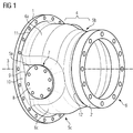
- the FIG. 1 shows a encapsulating housing reducer in a perspective view.
- the encapsulating housing reducing piece has a first flange 1 and a second flange 2.
- the first and the second flange 1, 2 are each formed as annular flanges, which are aligned with their flange surfaces approximately parallel to each other.
- the two flanges 1, 2 lie coaxially with a longitudinal axis 3 of the Kapselungsge Reifeneduzier Federationes.
- An encapsulation housing jacket 4 extends between the mutually facing ends of the two flanges 1, 2.
- the encapsulation housing jacket 4 connects in a fluid-tight manner to the first or the second flange 1, 2 and forms a circumferential movement about the longitudinal axis 3 between the two flanges 1, 2 a fluid-tight channel.
- the encapsulation housing jacket 4 has a first planar zone 5a.
- a second planar zone 5 b and a third planar zone 5 c are arranged symmetrically distributed around the longitudinal axis 3 in the circulation of the encapsulation housing jacket 4.
- Between the three planar zones 5a, 5b, 5c are each rotationally symmetrical lateral surface sections 6a, 6b, 6c arranged.
- the rotationally symmetrical lateral surface sections 6a, 6b, 6c are each aligned coaxially with the longitudinal axis 3, wherein the three rotationally symmetrical lateral surface sections 6a, 6b, 6c lie on one and the same orbit.
- the rotationally symmetrical lateral surface sections 6a, 6b, 6c respectively abut against the planar zones 5a, 5b, 5c and are connected to them in a fluid-tight manner. In the abutting region between the planar zones 5a, 5b, 5c and the respectively adjacent lateral surface sections 6a, 6b, 6c, transition regions are formed in order to obtain a rounded surface structure.
- a receiving space / fluid space is formed in the region of the planar zones 5a, 5b, 5c and the rotationally symmetrical lateral surface portions 6a, 6b, 6c, which has a substantially triangular cross-section, wherein the corners of the triangle are rounded.
- the corners are broken by the rotationally symmetrical lateral surface sections 6a, 6b, 6c.
- the sides of the triangular base are bounded by the flat zones 5a, 5b, 5c. Due to the uniform distribution of the flat zones 5a, 5b, 5c and the similarly circumferential lateral surface portions 6a, 6b, 6c, an equilateral triangular cross-section is formed.
- at least a portion of the receiving space of the encapsulating housing reducing piece formed between the two flanges 1, 2 is provided in the form of a cylindrical body with a substantially triangular base area and rounded corners.
- the other flange openings 7 are also closed with Blindflanschdeckeln. However, it can also be provided that, if necessary, different flange openings 7 are to be closed with different elements. In addition to blind flange covers 8, measuring lead bushings, overpressure protection devices or filter covers, etc. can also serve as various elements.
- the encapsulating housing jacket 4 passes fluid-tightly into the first flange 1 at its end facing the first flange 1.
- a bending edge 9 is arranged, via which a connection to the flange 1 is given.
- the surface normals of the planar zones 5a, 5b, 5c or the surface normals of the abutting surface of the first flange 1 are aligned substantially perpendicular to one another. This results in respect to the longitudinal axis 3, a radial extension of the flat zones 5a, 5b, 5c on the first flange 1.
- a circular section 10 is arranged, which via the respective bending edge 9 in a level zone 5a, 5b, 5c passes.
- Arc ends of the circular section 10 merge into a circular path, which defines a bent bending edge 11, via which the rotationally symmetrical lateral surface sections 6a, 6b, 6c abut against the first flange 1.
- Bend radii of the bent bending edges 11 between the first flange 1 and the rotationally symmetrical lateral surface sections 6a, 6b, 6c are each aligned coaxially with the longitudinal axis 3.
- the planar zones 5a, 5b, 5c and the rotationally symmetrical lateral surface sections 6a, 6b, 6c merge into a cross section-reduced rotationally symmetric section 12, which forms a Represents connection to the second flange 2.
- the cross-section-reduced rotationally symmetric section 12 is fluid-tightly connected both to the planar zones 5 a, 5 b, 5 c and the rotationally symmetrical lateral surface sections 6 a, 6 b, 6 c and the second flange 2.
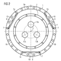
- Encapsulation housing jacket 4 having a first planar zone 5a, a second planar zone 5b and a third planar zone 5c.
- the adjoining circular sections 10 can be recognized on the flat zones 5a, 5b, 5c.
- Exemplary are in the FIG. 2 all located in the flat zones 5a, 5b, 5c flange openings 7 closed with a Blindflanschdeckel 8.
- the planar zones 5a, 5b, 5c are connected to one another in the direction of rotation via the rotationally symmetrical lateral surface sections 6a, 6b, 6c of the encapsulating housing jacket.
- the rotationally symmetrical lateral surface sections 6a, 6b, 6c are sections of an (imaginary) continuous rotationally symmetrical lateral surface of the encapsulation housing jacket.
- the flat zones 5a, 5b, 5c are formed by flattening in this rotationally symmetrical lateral surface.
- the bending edges 9 Craving in the projection according to FIG. 2 illustrated circular sections 10th
- the position of active conductors 13a, 13b, 13c to be positioned in the interior of the encapsulating housing reducing piece is symbolically shown.
- the active conductors 13a, 13b, 13c shown only partially in the plane in which they pierce the second flange 2.
- the active conductors 13a, 13b, 13c are arranged distributed on a circular path, which in each case define the vertices of an equilateral triangle on the circular path.
- the active conductors 13a, 13b, 13c are arranged electrically isolated from the encapsulating housing reducing piece.
- solid insulators can be provided, which are supported, for example, on the flanges 1, 2 or on further walls of the encapsulating housing reducing piece.
- the encapsulating housing reducing piece provides an encapsulating housing jacket 4 between the two flanges 1, 2, which is fluid-tight.
- a fluid-tight seal can be made there as well.
- the interior of the Kapselungsge Reifeneduzier Federationes be filled with an electrically insulating fluid, preferably an insulating gas or an insulating oil.
- Particularly suitable as insulating gas are sulfur hexafluoride or nitrogen or other suitable insulating gases.
- the fluid can be placed under an elevated pressure in the interior, whereby the electrical strength of the fluid is further improved in the rule.
- the interior of the encapsulating housing reducing piece is preferably equipped with a current transformer arrangement.
- FIG. 3 is a cut through that out of the FIGS. 1 and 2 known enclosure housing reducer shown.
- the sectional plane is selected such that the flange openings 7 located in the flat zones 5a, 5b, 5c are cut.
- FIG. 3 is the same visual axis as known from the Figure 2 known. It can be seen that a section of the encapsulating housing reducing piece has a substantially triangular cross section, which is broken at the triangular points by the rotationally symmetrical lateral surface sections 6a, 6b, 6c. For stability reasons, the ideal triangle sides are interspersed with reinforcements.
- the active conductors 13a, 13b, 13c are each surrounded by transducer cores 14a, 14b, 14c.
- the transducer cores 14a, 14b, 14c are formed, for example, from a ferromagnetic material and have a hollow cylindrical Structure on.
- the transducer cores 14a, 14b, 14c can be bundled during a current flow surrounding fields.
- the converter cores 14a, 14b, 14c can be designed in various shapes.
- FIG. 4 is a cross section through the from the FIGS. 1 . 2 and 3 known encapsulating housing reducer shown.
- respective dielectric shield elements 15a, 15b are arranged. It can be seen in the FIG. 4 the cranked course of the active conductor 13a, 13b, 13c, wherein due to the position of the cutting plane of the active conductor 13c is not immediately recognizable.
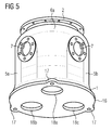
- FIG. 5 is that from the FIGS. 1 . 2 . 3 . 4 known Kapselungsge Reifeneduzier choir shown in a perspective view.
- the encapsulating housing reducer is according to FIG. 5 not yet completely completed, ie the flange openings 7 in the flat zones 5a, 5b, 5c are free of any overlap.
- the annular flange rings which surround the flange 7.
- a lid 16 is flanged.
- the lid 16 is designed substantially circular, wherein the diameter of the lid 16 corresponds to the outer diameter of the first flange 1.
- radial projections 17 are provided, which the first flange 1 tower over.
- the number of projections 17 corresponds to the number of rotationally symmetrical lateral surface sections 6a, 6b, 6c.
- the cover 16 is angularly rigid with the first flange and flanged fluid-tight. In the projections 17 thorough recesses are introduced, via which the lid 16 can be held together with flanged encapsulating housing reduced piece.
- the projections 17 are rigidly connected to a foundation, a supporting frame or the like.
- active conductors 13'a, 13'b located in the interior of the encapsulating housing reducing piece or other encapsulating housing assemblies can be electrically conductively connected to electrical conductors located outside the encapsulating housing reducing piece. These electrical conductors are led into the interior of the encapsulating housing reducing piece via cables which terminate in the cable bushings.
- the cable feedthrough is designed in the form of cable connectors, ie, the openings 18a, 18b, 18c are closed by cable sockets 19a, the cable sockets 19a are part of a fluid-tight wall of Kapselungsge Reifeneduzier Kunststoffes. For this purpose, the cable sockets 19 a on electrically insulated sections.
Landscapes
- Engineering & Computer Science (AREA)
- Power Engineering (AREA)
- Casings For Electric Apparatus (AREA)
- Measuring Fluid Pressure (AREA)
- Motor Or Generator Frames (AREA)
- Connector Housings Or Holding Contact Members (AREA)
- Installation Of Indoor Wiring (AREA)
- Gas-Insulated Switchgears (AREA)
Applications Claiming Priority (2)
| Application Number | Priority Date | Filing Date | Title |
|---|---|---|---|
| DE102009015539A DE102009015539A1 (de) | 2009-04-01 | 2009-04-01 | Kapselungsgehäusereduzierstück |
| PCT/EP2010/054107 WO2010112462A2 (de) | 2009-04-01 | 2010-03-29 | Kapselungsgehäusereduzierstück |
Publications (2)
| Publication Number | Publication Date |
|---|---|
| EP2415134A2 EP2415134A2 (de) | 2012-02-08 |
| EP2415134B1 true EP2415134B1 (de) | 2016-08-17 |
Family
ID=42674904
Family Applications (1)
| Application Number | Title | Priority Date | Filing Date |
|---|---|---|---|
| EP10714222.6A Not-in-force EP2415134B1 (de) | 2009-04-01 | 2010-03-29 | Kapselungsgehäusereduzierstück |
Country Status (7)
| Country | Link |
|---|---|
| US (1) | US8569617B2 (ru) |
| EP (1) | EP2415134B1 (ru) |
| CN (1) | CN102362402B (ru) |
| BR (1) | BRPI1014672A2 (ru) |
| DE (1) | DE102009015539A1 (ru) |
| RU (1) | RU2526027C2 (ru) |
| WO (1) | WO2010112462A2 (ru) |
Families Citing this family (7)
| Publication number | Priority date | Publication date | Assignee | Title |
|---|---|---|---|---|
| DE102011089391A1 (de) * | 2011-12-21 | 2013-06-27 | Siemens Aktiengesellschaft | Stromwandler und dessen Verwendung |
| DE102012221246A1 (de) * | 2012-11-21 | 2014-05-22 | Siemens Aktiengesellschaft | Elektroenergieübertragungseinrichtung |
| DE102013201155A1 (de) * | 2013-01-24 | 2014-07-24 | Siemens Aktiengesellschaft | Anordnung mit einer Zugentlastungsvorrichtung |
| DE102013211102A1 (de) | 2013-06-14 | 2014-12-31 | Siemens Aktiengesellschaft | Gestaltungsverfahren eines Hohlkörpers sowie Hohlkörper |
| EP3021436A1 (fr) | 2014-11-17 | 2016-05-18 | Siemens Aktiengesellschaft | Arrangement d'enveloppe métallique apte à encapsuler un ensemble de composants électriques |
| DE102017214970A1 (de) * | 2017-08-28 | 2019-02-28 | Siemens Aktiengesellschaft | Schalteinrichtung |
| EP3863135A1 (en) * | 2020-02-06 | 2021-08-11 | ABB Schweiz AG | Bushing for a medium voltage switchgear |
Family Cites Families (15)
| Publication number | Priority date | Publication date | Assignee | Title |
|---|---|---|---|---|
| DE7243233U (de) * | 1972-11-21 | 1973-03-22 | Siemens Ag | Metallgekapselte, druckgasisolierte Hochspannungsschaltanlage |
| DE2557644A1 (de) * | 1975-12-20 | 1977-06-30 | Bbc Brown Boveri & Cie | Dreiphasig gekapselte, druckgasisolierte hochspannungsschaltanlage |
| DE2852950C2 (de) * | 1978-12-05 | 1984-07-19 | Siemens AG, 1000 Berlin und 8000 München | Dreiphasige metallgekapselte, druckgasisolierte Schaltvorrichtung für Hochspannungsschaltanlagen |
| DE4445866A1 (de) * | 1994-12-22 | 1996-06-27 | Abb Patent Gmbh | Hochspannungsanlage |
| DE19519301A1 (de) * | 1995-05-26 | 1996-11-28 | Abb Management Ag | Trenner für eine metallgekapselte gasisolierte Hochspannungsschaltanlage |
| DE19633857A1 (de) * | 1996-08-16 | 1998-02-19 | Siemens Ag | Gekapselte, gasisolierte Hochspannungsanlage mit geschottetem Verbindungsbaustein |
| DE29806652U1 (de) * | 1998-04-03 | 1998-06-18 | Siemens AG, 80333 München | Gekapselter, dreiphasiger Leistungsschalter mit anschließenden Kapselungsbausteinen |
| WO2001024333A1 (en) | 1999-09-29 | 2001-04-05 | Hitachi, Ltd. | Gas insulated switch |
| DE10014678C2 (de) * | 2000-03-17 | 2002-02-07 | Siemens Ag | Filterbeutel |
| RU2260887C2 (ru) * | 2000-10-24 | 2005-09-20 | Ормасабаль И Сиа., С.А. | Соединительный узел для элементов электрических распределительных устройств |
| DE10254385B3 (de) * | 2002-11-18 | 2004-03-04 | Siemens Ag | Rohrförmiges Gehäuse einer druckgasisolierten Baugruppe für eine elektrische Anlage |
| DE10325685A1 (de) * | 2003-06-02 | 2004-12-30 | Siemens Ag | Freiluftdurchführung mit integriertem Trennschalter |
| FR2874122B1 (fr) * | 2004-08-06 | 2006-09-22 | Areva T & D Ag | Transformateur de courant de type triphase et poste electrique equipe d'un tel transformateur de courant |
| DE102006001237A1 (de) * | 2006-01-05 | 2007-07-12 | Siemens Ag | Gasisolierte, dreiphasige gekapselte Schaltanlage |
| FR2911014B1 (fr) * | 2006-12-27 | 2009-04-17 | Areva T & D Sa | Ensemble d'appareillage electrique comprenant un appareillage electrique a cuve metallique et un sectionneur de terre fixe a la cuve |
-
2009
- 2009-04-01 DE DE102009015539A patent/DE102009015539A1/de not_active Withdrawn
-
2010
- 2010-03-29 RU RU2011144033/07A patent/RU2526027C2/ru not_active IP Right Cessation
- 2010-03-29 CN CN201080013053.7A patent/CN102362402B/zh not_active Expired - Fee Related
- 2010-03-29 WO PCT/EP2010/054107 patent/WO2010112462A2/de active Application Filing
- 2010-03-29 EP EP10714222.6A patent/EP2415134B1/de not_active Not-in-force
- 2010-03-29 BR BRPI1014672A patent/BRPI1014672A2/pt not_active IP Right Cessation
- 2010-03-29 US US13/262,772 patent/US8569617B2/en active Active
Also Published As
| Publication number | Publication date |
|---|---|
| WO2010112462A2 (de) | 2010-10-07 |
| WO2010112462A3 (de) | 2010-12-29 |
| EP2415134A2 (de) | 2012-02-08 |
| BRPI1014672A2 (pt) | 2016-04-12 |
| CN102362402A (zh) | 2012-02-22 |
| CN102362402B (zh) | 2013-11-06 |
| RU2011144033A (ru) | 2013-05-10 |
| US8569617B2 (en) | 2013-10-29 |
| DE102009015539A1 (de) | 2010-10-07 |
| RU2526027C2 (ru) | 2014-08-20 |
| US20120037395A1 (en) | 2012-02-16 |
Similar Documents
| Publication | Publication Date | Title |
|---|---|---|
| EP2415134B1 (de) | Kapselungsgehäusereduzierstück | |
| EP0236974B1 (de) | Kombinierter Hochspannungsstrom- und -spannungswandler | |
| DE1803363A1 (de) | Elektrische Mittelspannungsleitung zur Leistungsuebertragung | |
| CH322444A (de) | Metallgekapselte elektrische Hochspannungs-Schaltanlage | |
| WO2019077096A1 (de) | Stromwandler mit fluid- oder ölpapierisolierung für hochspannung | |
| EP0037796A1 (de) | Gas- oder flüssigkeitsisolierter Stromwandler | |
| DD250806A5 (de) | Hochspannungsstromwandler und verfahren zur herstellung eines derartigen hochspannungsstromwandlers | |
| WO2010052189A2 (de) | Druckgasisolierte elektroenergieübertragungsanordnung | |
| DE4435359C2 (de) | Polsäule eines elektrischen Leistungsschalters | |
| DE2749545C2 (de) | Gasdicht an eine gekapselte Mittelspannungsschaltanlage anflanschbare Kupplungseinheit | |
| WO2012007415A2 (de) | Mehrphasig druckgasisoliertes kabeleinführungsmodul mit einer kapselung | |
| EP1407461B1 (de) | Durchführungswandler für eine elektrische schaltanlage | |
| DE3012163C2 (de) | Gas- oder flüssigkeitsisolierter Stromwandler | |
| DE102008024730A1 (de) | Anordnung mit einer gasdichten Messdurchführung | |
| WO2019091838A1 (de) | Phasenleiter sowie verfahren zum räumlichen fixieren eines armaturkörpers an einem phasenleitergrundkörper | |
| EP3254350B1 (de) | Kapselungsgehäuseanordnung | |
| EP3164919A1 (de) | Kabelendverschluss zur anbindung einer schaltanlage an ein hochspannungskabel | |
| DE19530163A1 (de) | Hochspannungsausleitungs- und durchführungsanordnung für Transformatoren und Drosselspulen | |
| EP3001433B1 (de) | Stützisolator geeignet für einen Transformator | |
| WO2018137900A2 (de) | Fluidisolierte elektroenergieübertragungseinrichtung | |
| WO2020224963A1 (de) | Elektroenergieübertragungseinrichtung | |
| DE19838356A1 (de) | Kupplungseinrichtung zur Verbindung von trennbaren Kontaktbolzen zwischen Schalträumen von Schaltanlagen | |
| DE19805068A1 (de) | Kabelmuffe | |
| DE1790290A1 (de) | Steckbare, zweiteilige anschlussvorrichtung fuer hochspannungskabel | |
| DE1807994A1 (de) | Wickelstromwandler |
Legal Events
| Date | Code | Title | Description |
|---|---|---|---|
| PUAI | Public reference made under article 153(3) epc to a published international application that has entered the european phase |
Free format text: ORIGINAL CODE: 0009012 |
|
| 17P | Request for examination filed |
Effective date: 20110916 |
|
| AK | Designated contracting states |
Kind code of ref document: A2 Designated state(s): AT BE BG CH CY CZ DE DK EE ES FI FR GB GR HR HU IE IS IT LI LT LU LV MC MK MT NL NO PL PT RO SE SI SK SM TR |
|
| DAX | Request for extension of the european patent (deleted) | ||
| RAP1 | Party data changed (applicant data changed or rights of an application transferred) |
Owner name: SIEMENS AKTIENGESELLSCHAFT |
|
| GRAP | Despatch of communication of intention to grant a patent |
Free format text: ORIGINAL CODE: EPIDOSNIGR1 |
|
| INTG | Intention to grant announced |
Effective date: 20160223 |
|
| GRAS | Grant fee paid |
Free format text: ORIGINAL CODE: EPIDOSNIGR3 |
|
| GRAA | (expected) grant |
Free format text: ORIGINAL CODE: 0009210 |
|
| AK | Designated contracting states |
Kind code of ref document: B1 Designated state(s): AT BE BG CH CY CZ DE DK EE ES FI FR GB GR HR HU IE IS IT LI LT LU LV MC MK MT NL NO PL PT RO SE SI SK SM TR |
|
| REG | Reference to a national code |
Ref country code: GB Ref legal event code: FG4D Free format text: NOT ENGLISH |
|
| REG | Reference to a national code |
Ref country code: CH Ref legal event code: EP |
|
| REG | Reference to a national code |
Ref country code: IE Ref legal event code: FG4D Free format text: LANGUAGE OF EP DOCUMENT: GERMAN |
|
| REG | Reference to a national code |
Ref country code: AT Ref legal event code: REF Ref document number: 821866 Country of ref document: AT Kind code of ref document: T Effective date: 20160915 |
|
| REG | Reference to a national code |
Ref country code: DE Ref legal event code: R096 Ref document number: 502010012212 Country of ref document: DE |
|
| REG | Reference to a national code |
Ref country code: CH Ref legal event code: NV Representative=s name: SIEMENS SCHWEIZ AG, CH |
|
| REG | Reference to a national code |
Ref country code: NL Ref legal event code: MP Effective date: 20160817 |
|
| REG | Reference to a national code |
Ref country code: LT Ref legal event code: MG4D |
|
| PG25 | Lapsed in a contracting state [announced via postgrant information from national office to epo] |
Ref country code: HR Free format text: LAPSE BECAUSE OF FAILURE TO SUBMIT A TRANSLATION OF THE DESCRIPTION OR TO PAY THE FEE WITHIN THE PRESCRIBED TIME-LIMIT Effective date: 20160817 Ref country code: FI Free format text: LAPSE BECAUSE OF FAILURE TO SUBMIT A TRANSLATION OF THE DESCRIPTION OR TO PAY THE FEE WITHIN THE PRESCRIBED TIME-LIMIT Effective date: 20160817 Ref country code: NO Free format text: LAPSE BECAUSE OF FAILURE TO SUBMIT A TRANSLATION OF THE DESCRIPTION OR TO PAY THE FEE WITHIN THE PRESCRIBED TIME-LIMIT Effective date: 20161117 Ref country code: NL Free format text: LAPSE BECAUSE OF FAILURE TO SUBMIT A TRANSLATION OF THE DESCRIPTION OR TO PAY THE FEE WITHIN THE PRESCRIBED TIME-LIMIT Effective date: 20160817 Ref country code: LT Free format text: LAPSE BECAUSE OF FAILURE TO SUBMIT A TRANSLATION OF THE DESCRIPTION OR TO PAY THE FEE WITHIN THE PRESCRIBED TIME-LIMIT Effective date: 20160817 Ref country code: IT Free format text: LAPSE BECAUSE OF FAILURE TO SUBMIT A TRANSLATION OF THE DESCRIPTION OR TO PAY THE FEE WITHIN THE PRESCRIBED TIME-LIMIT Effective date: 20160817 |
|
| PG25 | Lapsed in a contracting state [announced via postgrant information from national office to epo] |
Ref country code: ES Free format text: LAPSE BECAUSE OF FAILURE TO SUBMIT A TRANSLATION OF THE DESCRIPTION OR TO PAY THE FEE WITHIN THE PRESCRIBED TIME-LIMIT Effective date: 20160817 Ref country code: GR Free format text: LAPSE BECAUSE OF FAILURE TO SUBMIT A TRANSLATION OF THE DESCRIPTION OR TO PAY THE FEE WITHIN THE PRESCRIBED TIME-LIMIT Effective date: 20161118 Ref country code: SE Free format text: LAPSE BECAUSE OF FAILURE TO SUBMIT A TRANSLATION OF THE DESCRIPTION OR TO PAY THE FEE WITHIN THE PRESCRIBED TIME-LIMIT Effective date: 20160817 Ref country code: LV Free format text: LAPSE BECAUSE OF FAILURE TO SUBMIT A TRANSLATION OF THE DESCRIPTION OR TO PAY THE FEE WITHIN THE PRESCRIBED TIME-LIMIT Effective date: 20160817 Ref country code: PT Free format text: LAPSE BECAUSE OF FAILURE TO SUBMIT A TRANSLATION OF THE DESCRIPTION OR TO PAY THE FEE WITHIN THE PRESCRIBED TIME-LIMIT Effective date: 20161219 Ref country code: PL Free format text: LAPSE BECAUSE OF FAILURE TO SUBMIT A TRANSLATION OF THE DESCRIPTION OR TO PAY THE FEE WITHIN THE PRESCRIBED TIME-LIMIT Effective date: 20160817 |
|
| REG | Reference to a national code |
Ref country code: FR Ref legal event code: PLFP Year of fee payment: 8 |
|
| PG25 | Lapsed in a contracting state [announced via postgrant information from national office to epo] |
Ref country code: EE Free format text: LAPSE BECAUSE OF FAILURE TO SUBMIT A TRANSLATION OF THE DESCRIPTION OR TO PAY THE FEE WITHIN THE PRESCRIBED TIME-LIMIT Effective date: 20160817 Ref country code: RO Free format text: LAPSE BECAUSE OF FAILURE TO SUBMIT A TRANSLATION OF THE DESCRIPTION OR TO PAY THE FEE WITHIN THE PRESCRIBED TIME-LIMIT Effective date: 20160817 |
|
| REG | Reference to a national code |
Ref country code: DE Ref legal event code: R097 Ref document number: 502010012212 Country of ref document: DE |
|
| PG25 | Lapsed in a contracting state [announced via postgrant information from national office to epo] |
Ref country code: CZ Free format text: LAPSE BECAUSE OF FAILURE TO SUBMIT A TRANSLATION OF THE DESCRIPTION OR TO PAY THE FEE WITHIN THE PRESCRIBED TIME-LIMIT Effective date: 20160817 Ref country code: DK Free format text: LAPSE BECAUSE OF FAILURE TO SUBMIT A TRANSLATION OF THE DESCRIPTION OR TO PAY THE FEE WITHIN THE PRESCRIBED TIME-LIMIT Effective date: 20160817 Ref country code: SM Free format text: LAPSE BECAUSE OF FAILURE TO SUBMIT A TRANSLATION OF THE DESCRIPTION OR TO PAY THE FEE WITHIN THE PRESCRIBED TIME-LIMIT Effective date: 20160817 Ref country code: BG Free format text: LAPSE BECAUSE OF FAILURE TO SUBMIT A TRANSLATION OF THE DESCRIPTION OR TO PAY THE FEE WITHIN THE PRESCRIBED TIME-LIMIT Effective date: 20161117 Ref country code: SK Free format text: LAPSE BECAUSE OF FAILURE TO SUBMIT A TRANSLATION OF THE DESCRIPTION OR TO PAY THE FEE WITHIN THE PRESCRIBED TIME-LIMIT Effective date: 20160817 |
|
| PLBE | No opposition filed within time limit |
Free format text: ORIGINAL CODE: 0009261 |
|
| STAA | Information on the status of an ep patent application or granted ep patent |
Free format text: STATUS: NO OPPOSITION FILED WITHIN TIME LIMIT |
|
| 26N | No opposition filed |
Effective date: 20170518 |
|
| PG25 | Lapsed in a contracting state [announced via postgrant information from national office to epo] |
Ref country code: SI Free format text: LAPSE BECAUSE OF FAILURE TO SUBMIT A TRANSLATION OF THE DESCRIPTION OR TO PAY THE FEE WITHIN THE PRESCRIBED TIME-LIMIT Effective date: 20160817 |
|
| REG | Reference to a national code |
Ref country code: CH Ref legal event code: PCOW Free format text: NEW ADDRESS: WERNER-VON-SIEMENS-STRASSE 1, 80333 MUENCHEN (DE) |
|
| PG25 | Lapsed in a contracting state [announced via postgrant information from national office to epo] |
Ref country code: MC Free format text: LAPSE BECAUSE OF FAILURE TO SUBMIT A TRANSLATION OF THE DESCRIPTION OR TO PAY THE FEE WITHIN THE PRESCRIBED TIME-LIMIT Effective date: 20160817 |
|
| REG | Reference to a national code |
Ref country code: IE Ref legal event code: MM4A |
|
| PG25 | Lapsed in a contracting state [announced via postgrant information from national office to epo] |
Ref country code: LU Free format text: LAPSE BECAUSE OF NON-PAYMENT OF DUE FEES Effective date: 20170329 |
|
| PG25 | Lapsed in a contracting state [announced via postgrant information from national office to epo] |
Ref country code: IE Free format text: LAPSE BECAUSE OF NON-PAYMENT OF DUE FEES Effective date: 20170329 |
|
| REG | Reference to a national code |
Ref country code: BE Ref legal event code: MM Effective date: 20170331 |
|
| REG | Reference to a national code |
Ref country code: FR Ref legal event code: PLFP Year of fee payment: 9 |
|
| PGFP | Annual fee paid to national office [announced via postgrant information from national office to epo] |
Ref country code: GB Payment date: 20180312 Year of fee payment: 9 |
|
| PG25 | Lapsed in a contracting state [announced via postgrant information from national office to epo] |
Ref country code: BE Free format text: LAPSE BECAUSE OF NON-PAYMENT OF DUE FEES Effective date: 20170331 |
|
| PG25 | Lapsed in a contracting state [announced via postgrant information from national office to epo] |
Ref country code: MT Free format text: LAPSE BECAUSE OF FAILURE TO SUBMIT A TRANSLATION OF THE DESCRIPTION OR TO PAY THE FEE WITHIN THE PRESCRIBED TIME-LIMIT Effective date: 20160817 |
|
| PGFP | Annual fee paid to national office [announced via postgrant information from national office to epo] |
Ref country code: AT Payment date: 20190207 Year of fee payment: 10 |
|
| PG25 | Lapsed in a contracting state [announced via postgrant information from national office to epo] |
Ref country code: HU Free format text: LAPSE BECAUSE OF FAILURE TO SUBMIT A TRANSLATION OF THE DESCRIPTION OR TO PAY THE FEE WITHIN THE PRESCRIBED TIME-LIMIT; INVALID AB INITIO Effective date: 20100329 |
|
| PG25 | Lapsed in a contracting state [announced via postgrant information from national office to epo] |
Ref country code: CY Free format text: LAPSE BECAUSE OF NON-PAYMENT OF DUE FEES Effective date: 20160817 |
|
| GBPC | Gb: european patent ceased through non-payment of renewal fee |
Effective date: 20190329 |
|
| PG25 | Lapsed in a contracting state [announced via postgrant information from national office to epo] |
Ref country code: MK Free format text: LAPSE BECAUSE OF FAILURE TO SUBMIT A TRANSLATION OF THE DESCRIPTION OR TO PAY THE FEE WITHIN THE PRESCRIBED TIME-LIMIT Effective date: 20160817 |
|
| PG25 | Lapsed in a contracting state [announced via postgrant information from national office to epo] |
Ref country code: GB Free format text: LAPSE BECAUSE OF NON-PAYMENT OF DUE FEES Effective date: 20190329 |
|
| PG25 | Lapsed in a contracting state [announced via postgrant information from national office to epo] |
Ref country code: TR Free format text: LAPSE BECAUSE OF FAILURE TO SUBMIT A TRANSLATION OF THE DESCRIPTION OR TO PAY THE FEE WITHIN THE PRESCRIBED TIME-LIMIT Effective date: 20160817 |
|
| PG25 | Lapsed in a contracting state [announced via postgrant information from national office to epo] |
Ref country code: IS Free format text: LAPSE BECAUSE OF FAILURE TO SUBMIT A TRANSLATION OF THE DESCRIPTION OR TO PAY THE FEE WITHIN THE PRESCRIBED TIME-LIMIT Effective date: 20161217 |
|
| REG | Reference to a national code |
Ref country code: AT Ref legal event code: MM01 Ref document number: 821866 Country of ref document: AT Kind code of ref document: T Effective date: 20200329 |
|
| REG | Reference to a national code |
Ref country code: DE Ref legal event code: R081 Ref document number: 502010012212 Country of ref document: DE Owner name: SIEMENS ENERGY GLOBAL GMBH & CO. KG, DE Free format text: FORMER OWNER: SIEMENS AKTIENGESELLSCHAFT, 80333 MUENCHEN, DE |
|
| PG25 | Lapsed in a contracting state [announced via postgrant information from national office to epo] |
Ref country code: AT Free format text: LAPSE BECAUSE OF NON-PAYMENT OF DUE FEES Effective date: 20200329 |
|
| PGFP | Annual fee paid to national office [announced via postgrant information from national office to epo] |
Ref country code: DE Payment date: 20210519 Year of fee payment: 12 |
|
| PGFP | Annual fee paid to national office [announced via postgrant information from national office to epo] |
Ref country code: CH Payment date: 20210602 Year of fee payment: 12 |
|
| PGFP | Annual fee paid to national office [announced via postgrant information from national office to epo] |
Ref country code: FR Payment date: 20220324 Year of fee payment: 13 |
|
| REG | Reference to a national code |
Ref country code: DE Ref legal event code: R119 Ref document number: 502010012212 Country of ref document: DE |
|
| REG | Reference to a national code |
Ref country code: CH Ref legal event code: PL |
|
| PG25 | Lapsed in a contracting state [announced via postgrant information from national office to epo] |
Ref country code: LI Free format text: LAPSE BECAUSE OF NON-PAYMENT OF DUE FEES Effective date: 20220331 Ref country code: DE Free format text: LAPSE BECAUSE OF NON-PAYMENT OF DUE FEES Effective date: 20221001 Ref country code: CH Free format text: LAPSE BECAUSE OF NON-PAYMENT OF DUE FEES Effective date: 20220331 |
|
| PG25 | Lapsed in a contracting state [announced via postgrant information from national office to epo] |
Ref country code: FR Free format text: LAPSE BECAUSE OF NON-PAYMENT OF DUE FEES Effective date: 20230331 |