EP2415134B1 - Encapsulation housing reducing piece - Google Patents
Encapsulation housing reducing piece Download PDFInfo
- Publication number
- EP2415134B1 EP2415134B1 EP10714222.6A EP10714222A EP2415134B1 EP 2415134 B1 EP2415134 B1 EP 2415134B1 EP 10714222 A EP10714222 A EP 10714222A EP 2415134 B1 EP2415134 B1 EP 2415134B1
- Authority
- EP
- European Patent Office
- Prior art keywords
- flange
- encapsulation housing
- reducing piece
- zones
- housing reducing
- Prior art date
- Legal status (The legal status is an assumption and is not a legal conclusion. Google has not performed a legal analysis and makes no representation as to the accuracy of the status listed.)
- Not-in-force
Links
- 238000005538 encapsulation Methods 0.000 title claims description 39
- 239000012530 fluid Substances 0.000 claims description 25
- 238000005452 bending Methods 0.000 claims description 8
- 230000000994 depressogenic effect Effects 0.000 claims 1
- 238000007373 indentation Methods 0.000 claims 1
- 238000005259 measurement Methods 0.000 claims 1
- 239000004020 conductor Substances 0.000 description 36
- 239000003638 chemical reducing agent Substances 0.000 description 17
- 239000007789 gas Substances 0.000 description 7
- 239000000463 material Substances 0.000 description 6
- 230000007704 transition Effects 0.000 description 6
- 230000005540 biological transmission Effects 0.000 description 4
- 238000010292 electrical insulation Methods 0.000 description 4
- 210000004907 gland Anatomy 0.000 description 4
- 229910052751 metal Inorganic materials 0.000 description 4
- 239000002184 metal Substances 0.000 description 4
- IJGRMHOSHXDMSA-UHFFFAOYSA-N Atomic nitrogen Chemical compound N#N IJGRMHOSHXDMSA-UHFFFAOYSA-N 0.000 description 3
- 229910018503 SF6 Inorganic materials 0.000 description 3
- 230000000712 assembly Effects 0.000 description 3
- 238000000429 assembly Methods 0.000 description 3
- 238000000354 decomposition reaction Methods 0.000 description 3
- SFZCNBIFKDRMGX-UHFFFAOYSA-N sulfur hexafluoride Chemical compound FS(F)(F)(F)(F)F SFZCNBIFKDRMGX-UHFFFAOYSA-N 0.000 description 3
- 229960000909 sulfur hexafluoride Drugs 0.000 description 3
- XEEYBQQBJWHFJM-UHFFFAOYSA-N Iron Chemical compound [Fe] XEEYBQQBJWHFJM-UHFFFAOYSA-N 0.000 description 2
- 230000015572 biosynthetic process Effects 0.000 description 2
- 230000006378 damage Effects 0.000 description 2
- 238000005755 formation reaction Methods 0.000 description 2
- 150000002739 metals Chemical class 0.000 description 2
- 230000002787 reinforcement Effects 0.000 description 2
- 229910000838 Al alloy Inorganic materials 0.000 description 1
- 208000015943 Coeliac disease Diseases 0.000 description 1
- 230000002411 adverse Effects 0.000 description 1
- 239000003990 capacitor Substances 0.000 description 1
- 238000005266 casting Methods 0.000 description 1
- 238000010276 construction Methods 0.000 description 1
- 235000019788 craving Nutrition 0.000 description 1
- 238000005520 cutting process Methods 0.000 description 1
- 229910001873 dinitrogen Inorganic materials 0.000 description 1
- 238000009826 distribution Methods 0.000 description 1
- 230000005684 electric field Effects 0.000 description 1
- 239000003302 ferromagnetic material Substances 0.000 description 1
- -1 ferrous metals Chemical class 0.000 description 1
- 238000001914 filtration Methods 0.000 description 1
- 239000012212 insulator Substances 0.000 description 1
- 229910052742 iron Inorganic materials 0.000 description 1
- 230000009191 jumping Effects 0.000 description 1
- 239000007788 liquid Substances 0.000 description 1
- 238000004519 manufacturing process Methods 0.000 description 1
- 239000000203 mixture Substances 0.000 description 1
- 229910052757 nitrogen Inorganic materials 0.000 description 1
- 239000013307 optical fiber Substances 0.000 description 1
- 230000035515 penetration Effects 0.000 description 1
- 230000002093 peripheral effect Effects 0.000 description 1
- 239000007787 solid Substances 0.000 description 1
- 210000002435 tendon Anatomy 0.000 description 1
- 238000009827 uniform distribution Methods 0.000 description 1
- 230000000007 visual effect Effects 0.000 description 1
Images


Classifications
-
- H—ELECTRICITY
- H02—GENERATION; CONVERSION OR DISTRIBUTION OF ELECTRIC POWER
- H02B—BOARDS, SUBSTATIONS OR SWITCHING ARRANGEMENTS FOR THE SUPPLY OR DISTRIBUTION OF ELECTRIC POWER
- H02B13/00—Arrangement of switchgear in which switches are enclosed in, or structurally associated with, a casing, e.g. cubicle
- H02B13/02—Arrangement of switchgear in which switches are enclosed in, or structurally associated with, a casing, e.g. cubicle with metal casing
- H02B13/035—Gas-insulated switchgear
- H02B13/045—Details of casing, e.g. gas tightness
-
- H—ELECTRICITY
- H02—GENERATION; CONVERSION OR DISTRIBUTION OF ELECTRIC POWER
- H02B—BOARDS, SUBSTATIONS OR SWITCHING ARRANGEMENTS FOR THE SUPPLY OR DISTRIBUTION OF ELECTRIC POWER
- H02B13/00—Arrangement of switchgear in which switches are enclosed in, or structurally associated with, a casing, e.g. cubicle
- H02B13/02—Arrangement of switchgear in which switches are enclosed in, or structurally associated with, a casing, e.g. cubicle with metal casing
- H02B13/035—Gas-insulated switchgear
- H02B13/0356—Mounting of monitoring devices, e.g. current transformers
Definitions
- An encapsulating housing reducer is for example from the German utility model DE 298 06 652 U1 known. There, an encapsulated three-phase circuit breaker is described, to which encapsulation modules connect.
- One of the encapsulation blocks is designed as a encapsulating housing reducing piece, which has a first flange and a second flange reduced in cross-section with respect to the first flange. Between the first and second flange an encapsulating housing jacket is arranged.
- the known Kapselungsge Reifeneduzier Irish are preferably used to accommodate current transformers. For this purpose, various combinations of differently shaped encapsulating housing reducing pieces are provided. In order to reduce production costs, it is advantageous to use a large number of unitary components.
- the published patent DE 10 2006 001 037 A1 is a switchgear with a metal encapsulating removed.
- the encapsulating housing is composed of two parts, a base body in the form of a pot and a head part. Headboard and pot each have a flange, over the two parts are connected in a gas-tight manner by means of a screw connection.
- Encapsulated housing reduced pieces are used, for example, in gas-insulated switchgear.
- Gas-insulated switchgear units have fluid-tight encapsulating housings in their interior Active conductors are arranged. Active conductors serve to conduct an electric current.
- the active conductors are spaced apart from the encapsulating housings in the interior of the same electrically isolated.
- the interior is filled with an electrically insulating fluid.
- this fluid is an elevated pressure insulating gas such as sulfur hexafluoride.
- An encapsulating housing reducing piece is a fluid-tight encapsulating housing.
- Encapsulation housings surround the active conductors in a fluid-tight manner, so that the electrically insulating fluid can be held in the interior of the encapsulation housing.
- electrically insulating bushings are used to pass active conductors through a wall of the encapsulating housing.
- feedthroughs may be arranged in the region of flanges of the encapsulating housing reducing piece.
- the encapsulation housing jacket is designed such that a rigid connection between the two flanges is given by the encapsulation housing jacket.
- the orientation of the flanges should be chosen such that flange surfaces of the two flanges are approximately parallel to each other.
- flanges use annular flanges, which are coaxial with each other lie.
- the flanges are coaxial with a longitudinal axis of the encapsulating housing reducing piece. Between the encapsulating housing jacket and the flanges, a fluid-tight transition is formed in each case. Inside the encapsulating housing reducing piece, a volume is limited, which serves to form a fluid space.
- a volume with a triangular cross-sectional area results at least in sections within the receiving space of the encapsulation housing reduction piece, the corners of the triangular cross-sectional area being rounded off are.
- the interior of the Kapselungsge Reifeneduzier stoodes at least partially pronounced as a cylindrical receiving space whose end faces have triangular cross-sections, the corners of which are broken by rounding.
- planar zones and the rotationally symmetrical lateral surface sections are connected to one another in a fluid-tight manner and together form at least one peripheral section of the encapsulation housing jacket of the encapsulation housing reduction section.
- the encapsulation housing jacket fluid-tightly interconnects the two flanges so that a closed channel is provided between flange openings of the flanges.
- each active conductor in an encapsulated housing several phases of an electric power transmission system each active conductor in an encapsulated housing several phases of an electric power transmission system
- these active conductors can be arranged electrically isolated from each other, on the other these in particular in the presence of three phases in a triangle to each other be arranged.
- the fluid necessary for filling the interior of the encapsulating housing reducing piece such as sulfur hexafluoride gas or nitrogen gas or other gas mixtures, is reduced.
- a suitable choice of material for forming the encapsulation housing reducer it is possible, for example, to form the encapsulating housing reducing piece as a cast body, it being possible for metals such as iron or non-ferrous metals, in particular aluminum alloys, to be used as the casting material.
- a mechanically stable body is made available by the use of metals for the formation of the encapsulating housing reducing piece.
- the encapsulating housing reducing piece in a simple manner to ground potential. For example, it is possible to design gas-insulated switchgear whose outer surfaces carry ground potential and thus reliable contact protection of the active conductor located in the interior of the encapsulating housing is ensured.
- At least one, in particular all, planar zones pass over a bending edge into a circular section, which is connected to the first flange.
- the zones are distributed symmetrically in the circulation of the lateral surface sections.
- an equilateral triangular cross section with correspondingly rounded, broken corners arises in the section of the encapsulation housing reduction piece.
- a simple combination possibility is given. This allows a symmetrical construction of the encapsulating housing reducing piece and this can become more circular in the outer contours Insert molded enclosure sections.
- the rotationally symmetrical lateral surface sections should preferably lie on one and the same path, so that the receiving space has an at least substantially symmetrical shape.
- the cylindrical volume with the triangular cross section with rounded corners at its one end reduced cross-section in the direction of the second flange in a rotationally symmetrical lateral surface, which abuts the second flange.
- the volume having the triangular cross-section with rounded corners in the direction of the first flange should expand into the first flange.
- the second flange is projected in the same projection of the triangular cylindrical portion of the encapsulating housing jacket.
- the zones may be formed, for example, in that a substantially circular-cylindrical shell in the region of the shell receives corresponding flattenings, so that the zones represent, for example, seen in cross-section tendons in a circular cross-section and as a flattened zone is defined.
- the zones are formed as recessed impressions in a circular cylinder jacket section.
- the lateral surface sections provide protection of the recessed flat zones.
- the zones are formed by elevations on a circular cylinder jacket portion.
- a further advantageous embodiment can provide that a flange opening is arranged in at least one of the zones.
- a flange opening allows it to engage in the interior of the encapsulating housing Reducer, even if the first and the second flange are flanged with other assemblies. It is thus possible, for example, to carry out assembly work in the interior of the encapsulating housing reducing piece via a flange opening in a flat zone.
- a flange opening can be arranged in each of the zones.
- the flange opening may preferably have a circular opening cross-section, which is surrounded by a circular flange. To the annulus flange then other modules are flanged, so that the flange opening can be completed if necessary or sealed fluid-tight.
- a flange opening can be closed fluid-tight by a blind cover.
- the flange opening is closed by an overpressure safety device.
- the interior of the encapsulating housing reducer is filled with a pressurized fluid.
- a pressurized fluid is, for example, a gas or a liquid.
- a pressure difference generally arises with respect to a medium surrounding the encapsulating housing reducing piece, with the pressure of the medium surrounding the encapsulating housing generally being lower as the pressure inside the encapsulating housing reducer.
- Unforeseen external influences or disturbances can lead to an overpressure in the interior of the encapsulating housing reducing piece, so that destruction of the encapsulating housing reducing piece or endangering of people can occur.
- an overpressure protection device can be placed on a flange opening in a zone and thus the flange opening can be closed. If the pressure in the interior of the encapsulating housing reducing piece is too great, a discharge of fluid from the interior into the environment of the encapsulating housing reducing piece can take place via the overpressure securing device when a limiting pressure is reached.
- a further advantageous embodiment can provide that the flange opening is closed by a measuring line bushing.
- test lead bushing allows this.
- the test lead bushing can for example be flanged over a flange opening in one of the zones.
- the flange opening is closed with a filter cover.
- the interior of the encapsulating housing is filled with an electrically insulating fluid.
- an electrically insulating fluid When arcing occurs o. ⁇ ., It may cause decomposition of the electrically insulating fluid, with decomposition products, which may adversely affect the electrical insulation capacity of the fluid.
- the filter cover By closing the flange opening with a filter cover, there is a possibility of filtering out such decomposition products from the fluid.
- the filter cover is placed in a fluid-tight manner on the flange opening and has a receiving area for receiving a filter material on a wall accessible to the interior of the encapsulating housing.
- Flange openings located in the planar zones of an encapsulation housing reducer may be variously sealed as needed.
- a further advantageous embodiment may provide that the first flange of a Kapselungsge Reifeneduzier thoroughlyes is closed by a cover having a plurality of the first flange radially projecting projections on its circumference, on which the encapsulating housing Reduzier gland is supported.
- the lid is provided with the same number of openings and corresponding cable sockets, as the encapsulating housing Reduzier institutions has planar zones.
- the projections projecting beyond the first flange it is possible to attach holders for positioning the encapsulating housing reducing piece to these formations, so that the encapsulating housing reducing piece is stabilized in its position.
- the lid is penetrated by cable glands.
- Cable glands are necessary to introduce electrical cables with their electrical conductors in the interior of a gas-insulated switchgear.
- electrical insulation of the active conductor is ensured by the there electrically insulating fluid.
- the electrical insulation of the active conductor of an electric power transmission network is ensured by an insulating layer of the cable.
- Cable bushings are used firstly to introduce a cable into the interior of the encapsulating housing reducing piece.
- the cable glands serve to control an electric field around the cable ends located in the area of the cable glands.
- a cable feedthrough has, for example, a cable socket and a cable plug, wherein the cable plug is inserted into the cable socket and there is an electrical interface of the electrical conductor of the cable is added to an active conductor inside the Kapselungsge Reifeneduzier flourishes.
- the cable bushing is part of a fluid-tight wall of the Kapselungsge Reifeneduzier réellees and prevents leakage of electrically insulating fluid from the Kapselungsge Reifeneduzier mutual.
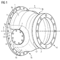
- the FIG. 1 shows a encapsulating housing reducer in a perspective view.
- the encapsulating housing reducing piece has a first flange 1 and a second flange 2.
- the first and the second flange 1, 2 are each formed as annular flanges, which are aligned with their flange surfaces approximately parallel to each other.
- the two flanges 1, 2 lie coaxially with a longitudinal axis 3 of the Kapselungsge Reifeneduzier Federationes.
- An encapsulation housing jacket 4 extends between the mutually facing ends of the two flanges 1, 2.
- the encapsulation housing jacket 4 connects in a fluid-tight manner to the first or the second flange 1, 2 and forms a circumferential movement about the longitudinal axis 3 between the two flanges 1, 2 a fluid-tight channel.
- the encapsulation housing jacket 4 has a first planar zone 5a.
- a second planar zone 5 b and a third planar zone 5 c are arranged symmetrically distributed around the longitudinal axis 3 in the circulation of the encapsulation housing jacket 4.
- Between the three planar zones 5a, 5b, 5c are each rotationally symmetrical lateral surface sections 6a, 6b, 6c arranged.
- the rotationally symmetrical lateral surface sections 6a, 6b, 6c are each aligned coaxially with the longitudinal axis 3, wherein the three rotationally symmetrical lateral surface sections 6a, 6b, 6c lie on one and the same orbit.
- the rotationally symmetrical lateral surface sections 6a, 6b, 6c respectively abut against the planar zones 5a, 5b, 5c and are connected to them in a fluid-tight manner. In the abutting region between the planar zones 5a, 5b, 5c and the respectively adjacent lateral surface sections 6a, 6b, 6c, transition regions are formed in order to obtain a rounded surface structure.
- a receiving space / fluid space is formed in the region of the planar zones 5a, 5b, 5c and the rotationally symmetrical lateral surface portions 6a, 6b, 6c, which has a substantially triangular cross-section, wherein the corners of the triangle are rounded.
- the corners are broken by the rotationally symmetrical lateral surface sections 6a, 6b, 6c.
- the sides of the triangular base are bounded by the flat zones 5a, 5b, 5c. Due to the uniform distribution of the flat zones 5a, 5b, 5c and the similarly circumferential lateral surface portions 6a, 6b, 6c, an equilateral triangular cross-section is formed.
- at least a portion of the receiving space of the encapsulating housing reducing piece formed between the two flanges 1, 2 is provided in the form of a cylindrical body with a substantially triangular base area and rounded corners.
- the other flange openings 7 are also closed with Blindflanschdeckeln. However, it can also be provided that, if necessary, different flange openings 7 are to be closed with different elements. In addition to blind flange covers 8, measuring lead bushings, overpressure protection devices or filter covers, etc. can also serve as various elements.
- the encapsulating housing jacket 4 passes fluid-tightly into the first flange 1 at its end facing the first flange 1.
- a bending edge 9 is arranged, via which a connection to the flange 1 is given.
- the surface normals of the planar zones 5a, 5b, 5c or the surface normals of the abutting surface of the first flange 1 are aligned substantially perpendicular to one another. This results in respect to the longitudinal axis 3, a radial extension of the flat zones 5a, 5b, 5c on the first flange 1.
- a circular section 10 is arranged, which via the respective bending edge 9 in a level zone 5a, 5b, 5c passes.
- Arc ends of the circular section 10 merge into a circular path, which defines a bent bending edge 11, via which the rotationally symmetrical lateral surface sections 6a, 6b, 6c abut against the first flange 1.
- Bend radii of the bent bending edges 11 between the first flange 1 and the rotationally symmetrical lateral surface sections 6a, 6b, 6c are each aligned coaxially with the longitudinal axis 3.
- the planar zones 5a, 5b, 5c and the rotationally symmetrical lateral surface sections 6a, 6b, 6c merge into a cross section-reduced rotationally symmetric section 12, which forms a Represents connection to the second flange 2.
- the cross-section-reduced rotationally symmetric section 12 is fluid-tightly connected both to the planar zones 5 a, 5 b, 5 c and the rotationally symmetrical lateral surface sections 6 a, 6 b, 6 c and the second flange 2.
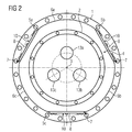
- Encapsulation housing jacket 4 having a first planar zone 5a, a second planar zone 5b and a third planar zone 5c.
- the adjoining circular sections 10 can be recognized on the flat zones 5a, 5b, 5c.
- Exemplary are in the FIG. 2 all located in the flat zones 5a, 5b, 5c flange openings 7 closed with a Blindflanschdeckel 8.
- the planar zones 5a, 5b, 5c are connected to one another in the direction of rotation via the rotationally symmetrical lateral surface sections 6a, 6b, 6c of the encapsulating housing jacket.
- the rotationally symmetrical lateral surface sections 6a, 6b, 6c are sections of an (imaginary) continuous rotationally symmetrical lateral surface of the encapsulation housing jacket.
- the flat zones 5a, 5b, 5c are formed by flattening in this rotationally symmetrical lateral surface.
- the bending edges 9 Craving in the projection according to FIG. 2 illustrated circular sections 10th
- the position of active conductors 13a, 13b, 13c to be positioned in the interior of the encapsulating housing reducing piece is symbolically shown.
- the active conductors 13a, 13b, 13c shown only partially in the plane in which they pierce the second flange 2.
- the active conductors 13a, 13b, 13c are arranged distributed on a circular path, which in each case define the vertices of an equilateral triangle on the circular path.
- the active conductors 13a, 13b, 13c are arranged electrically isolated from the encapsulating housing reducing piece.
- solid insulators can be provided, which are supported, for example, on the flanges 1, 2 or on further walls of the encapsulating housing reducing piece.
- the encapsulating housing reducing piece provides an encapsulating housing jacket 4 between the two flanges 1, 2, which is fluid-tight.
- a fluid-tight seal can be made there as well.
- the interior of the Kapselungsge Reifeneduzier Federationes be filled with an electrically insulating fluid, preferably an insulating gas or an insulating oil.
- Particularly suitable as insulating gas are sulfur hexafluoride or nitrogen or other suitable insulating gases.
- the fluid can be placed under an elevated pressure in the interior, whereby the electrical strength of the fluid is further improved in the rule.
- the interior of the encapsulating housing reducing piece is preferably equipped with a current transformer arrangement.
- FIG. 3 is a cut through that out of the FIGS. 1 and 2 known enclosure housing reducer shown.
- the sectional plane is selected such that the flange openings 7 located in the flat zones 5a, 5b, 5c are cut.
- FIG. 3 is the same visual axis as known from the Figure 2 known. It can be seen that a section of the encapsulating housing reducing piece has a substantially triangular cross section, which is broken at the triangular points by the rotationally symmetrical lateral surface sections 6a, 6b, 6c. For stability reasons, the ideal triangle sides are interspersed with reinforcements.
- the active conductors 13a, 13b, 13c are each surrounded by transducer cores 14a, 14b, 14c.
- the transducer cores 14a, 14b, 14c are formed, for example, from a ferromagnetic material and have a hollow cylindrical Structure on.
- the transducer cores 14a, 14b, 14c can be bundled during a current flow surrounding fields.
- the converter cores 14a, 14b, 14c can be designed in various shapes.
- FIG. 4 is a cross section through the from the FIGS. 1 . 2 and 3 known encapsulating housing reducer shown.
- respective dielectric shield elements 15a, 15b are arranged. It can be seen in the FIG. 4 the cranked course of the active conductor 13a, 13b, 13c, wherein due to the position of the cutting plane of the active conductor 13c is not immediately recognizable.
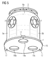
- FIG. 5 is that from the FIGS. 1 . 2 . 3 . 4 known Kapselungsge Reifeneduzier choir shown in a perspective view.
- the encapsulating housing reducer is according to FIG. 5 not yet completely completed, ie the flange openings 7 in the flat zones 5a, 5b, 5c are free of any overlap.
- the annular flange rings which surround the flange 7.
- a lid 16 is flanged.
- the lid 16 is designed substantially circular, wherein the diameter of the lid 16 corresponds to the outer diameter of the first flange 1.
- radial projections 17 are provided, which the first flange 1 tower over.
- the number of projections 17 corresponds to the number of rotationally symmetrical lateral surface sections 6a, 6b, 6c.
- the cover 16 is angularly rigid with the first flange and flanged fluid-tight. In the projections 17 thorough recesses are introduced, via which the lid 16 can be held together with flanged encapsulating housing reduced piece.
- the projections 17 are rigidly connected to a foundation, a supporting frame or the like.
- active conductors 13'a, 13'b located in the interior of the encapsulating housing reducing piece or other encapsulating housing assemblies can be electrically conductively connected to electrical conductors located outside the encapsulating housing reducing piece. These electrical conductors are led into the interior of the encapsulating housing reducing piece via cables which terminate in the cable bushings.
- the cable feedthrough is designed in the form of cable connectors, ie, the openings 18a, 18b, 18c are closed by cable sockets 19a, the cable sockets 19a are part of a fluid-tight wall of Kapselungsge Reifeneduzier Kunststoffes. For this purpose, the cable sockets 19 a on electrically insulated sections.
Landscapes
- Engineering & Computer Science (AREA)
- Power Engineering (AREA)
- Casings For Electric Apparatus (AREA)
- Measuring Fluid Pressure (AREA)
- Motor Or Generator Frames (AREA)
- Gas-Insulated Switchgears (AREA)
- Connector Housings Or Holding Contact Members (AREA)
- Installation Of Indoor Wiring (AREA)
Description
Die Erfindung bezieht sich auf ein Kapselungsgehäusereduzierstück mit einem ersten Flansch und einem gegenüber dem ersten Flansch querschnittreduzierten zweiten Flansch, zwischen welchen sich ein Kapselungsgehäusemantel erstreckt, wobei in dem Kapselungsgehäusemantel mehrere ebene Zonen angeordnet sind, zwischen welchen Mantelflächenabschnitte rotationssymmetrisch angeordnet sind.The invention relates to a Kapselungsgehäusereduzierstück with a first flange and a comparison with the first flange querschnittreduzierten second flange, between which extends a Kapselungsgehäusemantel, wherein in the Kapselungsgehäusemantel a plurality of planar zones are arranged between which lateral surface portions are arranged rotationally symmetrical.
Ein Kapselungsgehäusereduzierstück ist beispielsweise aus dem deutschen Gebrauchsmuster
Der Offenlegungsschrift
Aus der Patentschrift
Im Zuge einer zunehmenden Miniaturisierung ist eine Massereduzierung von Kapselungsgehäusen wünschenswert. Darüber hinaus soll trotz Miniaturisierung die Nutzbarkeit des Kapselungsgehäusereduzierstückes jedoch möglichst nicht beeinträchtigt werden.In the course of increasing miniaturization, mass reduction of encapsulating housings is desirable. In addition to the usability of Kapselungsgehäusereduzierstückes should not be affected, however, despite miniaturization.
Daher ist es Aufgabe der Erfindung, den Materialbedarf für ein Kapselungsgehäusereduzierstück zu reduzieren, wobei eine universelle Nutzbarkeit weiterhin erhalten bleiben soll.It is therefore an object of the invention to reduce the material requirements for a encapsulating housing Reducer, wherein a universal usability is to be maintained.
Erfindungsgemäß wird dies bei einem Kapselungsgehäusereduzierstück der eingangs genannten Art dadurch gelöst, dass die Zonen durch Abplattungen eines Kreiszylindermantels gebildet sind.This is achieved according to the invention in a encapsulating housing reducing piece of the type mentioned at the outset in that the zones are formed by flattening a circular cylinder jacket.
Kapselungsgehäusereduzierstücke sind beispielsweise an gasisolierten Schaltanlagen eingesetzt. Gasisolierte Schaltanlagen weisen fluiddichte Kapselungsgehäuse auf, in deren Inneren Aktivleiter angeordnet sind. Aktivleiter dienen einem Leiten eines elektrischen Stromes. Die Aktivleiter sind dazu beabstandet zu den Kapselungsgehäusen im Innern derselben elektrisch isoliert positioniert. Um eine elektrische Isolation zwischen den Aktivleitern und den Kapselungsgehäusen zu gewährleisten, ist das Innere mit einem elektrisch isolierenden Fluid befüllt. Vorzugsweise ist dieses Fluid ein unter erhöhtem Druck stehendes Isoliergas wie beispielsweise Schwefelhexafluorid. Ein Kapselungsgehäusereduzierstück ist ein fluiddichtes Kapselungsgehäuse.Encapsulated housing reduced pieces are used, for example, in gas-insulated switchgear. Gas-insulated switchgear units have fluid-tight encapsulating housings in their interior Active conductors are arranged. Active conductors serve to conduct an electric current. The active conductors are spaced apart from the encapsulating housings in the interior of the same electrically isolated. In order to ensure electrical insulation between the active conductors and the encapsulating housings, the interior is filled with an electrically insulating fluid. Preferably, this fluid is an elevated pressure insulating gas such as sulfur hexafluoride. An encapsulating housing reducing piece is a fluid-tight encapsulating housing.
Kapselungsgehäuse umgeben die Aktivleiter fluiddicht, so dass das elektrisch isolierende Fluid im Innern des Kapselungsgehäuses gehalten werden kann. Gegebenenfalls sind zu einem Hindurchführen von Aktivleitern durch eine Wandung des Kapselungsgehäuses elektrisch isolierende Durchführungen einzusetzen. Beispielsweise können derartige Durchführungen im Bereich von Flanschen des Kapselungsgehäusereduzierstückes angeordnet sein.Encapsulation housings surround the active conductors in a fluid-tight manner, so that the electrically insulating fluid can be held in the interior of the encapsulation housing. Optionally, electrically insulating bushings are used to pass active conductors through a wall of the encapsulating housing. For example, such feedthroughs may be arranged in the region of flanges of the encapsulating housing reducing piece.
Zwischen erstem und zweitem Flansch erstreckt sich der Kapselungsgehäusemantel. Dabei ist der Kapselungsgehäusemantel derart ausgelegt, dass eine winkelstarre Verbindung zwischen den beiden Flanschen über den Kapselungsgehäusemantel gegeben ist. Vorzugsweise sollte die Ausrichtung der Flansche derart gewählt sein, dass Flanschflächen der beiden Flansche annähernd parallel zueinander liegen. Vorteilhafterweise sind als Flansche Ringflansche einzusetzen, welche koaxial zueinander liegen. Vorzugsweise liegen die Flansche koaxial zu einer Längsachse des Kapselungsgehäusereduzierstückes. Zwischen dem Kapselungsgehäusemantel und den Flanschen ist jeweils ein fluiddichter Übergang gebildet. Im Innern des Kapselungsgehäusereduzierstückes ist ein Volumen begrenzt, welches der Ausbildung eines Fluidraumes dient.Between the first and second flange of the encapsulating housing jacket extends. In this case, the encapsulation housing jacket is designed such that a rigid connection between the two flanges is given by the encapsulation housing jacket. Preferably, the orientation of the flanges should be chosen such that flange surfaces of the two flanges are approximately parallel to each other. Advantageously, as flanges use annular flanges, which are coaxial with each other lie. Preferably, the flanges are coaxial with a longitudinal axis of the encapsulating housing reducing piece. Between the encapsulating housing jacket and the flanges, a fluid-tight transition is formed in each case. Inside the encapsulating housing reducing piece, a volume is limited, which serves to form a fluid space.
Durch eine Ausgestaltung des Kapselungsgehäusemantels mit mehreren Zonen die eben ausgeformt sind, wobei diese Zonen über zueinander koaxial angeordnete rotationssymmetrische Mantelflächenabschnitten untereinander verbunden sind, ergibt sich im Innern des Aufnahmeraumes des Kapselungsgehäusereduzierstückes zumindest abschnittsweise ein Volumen mit einer dreieckigen Querschnittsfläche, wobei die Ecken der dreieckigen Querschnittsfläche abgerundet sind. So ist das Innere des Kapselungsgehäusereduzierstückes zumindest teilweise als zylindrischer Aufnahmeraum ausgeprägt, dessen Stirnseiten dreieckige Querschnitte aufweisen, deren Ecken von Abrundungen gebrochen sind. Die ebenen Zonen und die rotationssymmetrischen Mantelflächenabschnitte sind fluiddicht miteinander verbunden und bilden gemeinsam zumindest einen umlaufenden Abschnitt des Kapselungsgehäusemantels des Kapselungsgehäusereduzierstückes. Der Kapselungsgehäusemantel verbindet die beiden Flansche fluiddicht miteinander, so das zwischen Flanschöffnungen der Flansche ein abgeschlossener Kanal gegeben ist.As a result of an embodiment of the encapsulating housing jacket with a plurality of zones that are just formed, these zones being interconnected via rotationally symmetrical lateral surface sections arranged coaxially with one another, a volume with a triangular cross-sectional area results at least in sections within the receiving space of the encapsulation housing reduction piece, the corners of the triangular cross-sectional area being rounded off are. Thus, the interior of the Kapselungsgehäusereduzierstückes at least partially pronounced as a cylindrical receiving space whose end faces have triangular cross-sections, the corners of which are broken by rounding. The planar zones and the rotationally symmetrical lateral surface sections are connected to one another in a fluid-tight manner and together form at least one peripheral section of the encapsulation housing jacket of the encapsulation housing reduction section. The encapsulation housing jacket fluid-tightly interconnects the two flanges so that a closed channel is provided between flange openings of the flanges.
Insbesondere bei einem Einsatz derartiger Kapselungsgehäusereduzierstücke in mehrphasigen gasisolierten Schaltanlagen, die in Kapselungsgehäusen jeweils Aktivleiter mehrere Phasen eines Elektroenergieübertragungssystemes aufnehmen, können diese Aktivleiter zum einen elektrisch isoliert zueinander angeordnet sein, zum anderen können diese insbesondere bei dem Vorhandensein von drei Phasen in einem Dreieck zueinander angeordnet sein. Dadurch ergibt sich ein ausreichend dimensionierter Aufnahmeraum im Innern des Kapselungsgehäusereduzierstückes, welcher ein ausreichendes Volumen zur Aufnahme von Aktivleitern der drei Phasen zur Verfügung stellt und aufgrund der ebenen Zonen gegenüber herkömmlichen kreiszylinderförmigen Aufnahmeräumen ein reduziertes Innenvolumen aufweist. Damit wird das zum Befüllen des Innern des Kapselungsgehäusereduzierstückes notwendige Fluid, wie beispielsweise Schwefelhexafluoridgas oder Stickstoffgas oder andere Gasgemische, reduziert. Gegenüber einem herkömmlichen kreisförmigen Querschnitt des Kapselungsgehäusemantels sind so zwar hinsichtlich einer Druckfestigkeit Einschränkungen zu erwarten, jedoch können bei einer geeigneten Materialwahl zur Ausformung des Kapselungsgehäusereduzierstückes ausreichende Druckfestigkeiten erzielt werden. So ist es beispielsweise möglich, das Kapselungsgehäusereduzierstück als Gusskörper auszuformen, wobei als Gussmaterial Metalle wie Eisen- oder Nichteisenmetalle, insbesondere Aluminiumlegierungen zum Einsatz gelangen können. Zum einen wird durch den Einsatz von Metallen zur Ausbildung des Kapselungsgehäusereduzierstückes ein mechanisch stabiler Körper zur Verfügung gestellt. Zum anderen besteht die Möglichkeit, das Kapselungsgehäusereduzierstück in einfacher Weise mit Erdpotential zu beaufschlagen. So ist es beispielsweise möglich, gasisolierte Schaltanlagen auszubilden, deren äußere Oberflächen Erdpotential führen und so ein zuverlässiger Berührungsschutz der im Innern der Kapselungsgehäuse befindlichen Aktivleiter gewährleistet ist.In particular, when using such Kapselungsgehäusereduzierstücke in multi-phase gas-insulated switchgear recording each active conductor in an encapsulated housing several phases of an electric power transmission system, these active conductors can be arranged electrically isolated from each other, on the other these in particular in the presence of three phases in a triangle to each other be arranged. This results in a sufficiently large receiving space in the interior of the Kapselungsgehäusereduzierstückes, which provides a sufficient volume for receiving active conductors of the three phases available and has a reduced internal volume due to the flat zones compared to conventional circular cylindrical receiving spaces. Thus, the fluid necessary for filling the interior of the encapsulating housing reducing piece, such as sulfur hexafluoride gas or nitrogen gas or other gas mixtures, is reduced. Compared with a conventional circular cross-section of the encapsulating housing jacket, restrictions in terms of compressive strength are to be expected, but adequate compressive strengths can be achieved with a suitable choice of material for forming the encapsulation housing reducer. Thus, it is possible, for example, to form the encapsulating housing reducing piece as a cast body, it being possible for metals such as iron or non-ferrous metals, in particular aluminum alloys, to be used as the casting material. On the one hand, a mechanically stable body is made available by the use of metals for the formation of the encapsulating housing reducing piece. On the other hand, there is the possibility of applying the encapsulating housing reducing piece in a simple manner to ground potential. For example, it is possible to design gas-insulated switchgear whose outer surfaces carry ground potential and thus reliable contact protection of the active conductor located in the interior of the encapsulating housing is ensured.
Vorteilhaft kann weiter vorgesehen sein, dass zumindestens eine, insbesondere alle ebenen Zonen über eine Biegekante in einen Kreisabschnitt übergehen, welcher mit dem ersten Flansch verbunden ist.Advantageously, it can further be provided that at least one, in particular all, planar zones pass over a bending edge into a circular section, which is connected to the first flange.
Über die Kreisabschnitte kann eine radiale Erweiterung des Kapselungsgehäusereduzierstückes erfolgen. Die Kreisabschnitte gewährleisten einen fluiddichten Übergang zwischen den Zonen zu dem ersten Flansch, welcher vorzugsweise ein Kreisflansch ist. Der Kreisbogen des Kreisabschnittes stößt an den ersten Flansch. Flächennormalen einer Zone und eines angrenzenden Kreisabschnittes sollten vorzugsweise im Wesentlichen lotrecht zueinander stehen. Die Biegekante verläuft parallel zu einer Sehne des Kreisabschnittes. Die Enden des Kreisbogens des Kreisabschnittes stoßen an Übergänge der rotationssymmetrischen Mantelflächenabschnitte, die an die benachbarte ebene Zone stoßen. Übergänge zwischen erstem Flansch und rotationssymmetrischen Flächenabschnitten sind als Abwinkelungen ausgeführt, wobei eine Bahn der Abwinkelungen in Übergangs- bzw. Stoßbereichen koaxial zu dem Verlauf der rotationssymmetrischen Mantelflächenabschnitte sowie zu dem ersten Flansch verläuft.About the circular sections can be made a radial extension of Kapselungsgehäusereduzierstückes. The circular sections ensure a fluid-tight transition between the zones to the first flange, which is preferably a circular flange. The circular arc of the circle section abuts the first flange. Surface normals of a zone and an adjacent circle section should preferably be substantially perpendicular to one another. The bending edge runs parallel to a chord of the circular section. The ends of the circular arc of the circular section abut transitions of the rotationally symmetrical lateral surface sections which abut the adjacent planar zone. Transitions between the first flange and rotationally symmetrical surface sections are designed as bends, wherein a path of the bends in transition or impact areas runs coaxially to the course of the rotationally symmetrical lateral surface sections and to the first flange.
Weiterhin kann vorteilhaft vorgesehen sein, dass die Zonen symmetrisch im Umlauf der Mantelflächenabschnitte verteilt sind.Furthermore, it can be advantageously provided that the zones are distributed symmetrically in the circulation of the lateral surface sections.
Durch eine symmetrische Verteilung der Zonen in dem Kapselungsgehäusemantel entsteht im Abschnitt des Kapselungsgehäusereduzierstückes ein gleichseitig dreieckiger Querschnitt mit entsprechend abgerundet gebrochenen Ecken. Damit wird insbesondere bei einer Kombination des Kapselungsgehäusereduzierstückes, beispielsweise mit Kapselungsgehäusen, die im Wesentlichen kreisförmige Querschnitte aufweisen und somit zumindest im Wesentlichen kreiszylindrische Aufnahmeräume in ihrem Inneren zur Verfügung stellen, eine einfache Kombinationsmöglichkeit gegeben. Damit ist ein symmetrischer Aufbau des Kapselungsgehäusereduzierstückes ermöglicht und dieses kann sich in die äußeren Konturen herkömmlicher kreisförmig geformter Kapselungsgehäuseabschnitte einfügen. Die rotationssymmetrischen Mantelflächenabschnitte sollten vorzugsweise auf ein und derselben Bahn liegen, so dass der Aufnahmeraum eine zumindest im Wesentlichen symmetrische Gestalt aufweist. Vorteilhafterweise sollte vorgesehen sein, dass das zylindrische Volumen mit dem dreieckigen Querschnitt mit abgerundeten Ecken an seinem einen Ende querschnittsreduziert in Richtung des zweiten Flansches in eine rotationssymmetrische Mantelfläche übergeht, die an den zweiten Flansch stößt. Mit dem anderen Ende sollte das Volumen mit dem dreieckigen Querschnitt mit abgerundeten Ecken in Richtung des ersten Flansches sich erweiternd in den ersten Flansch übergehen. In einer Projektion in Richtung der Längsachse überragt der erste Flansch mit seinem Querschnitt den dreieckförmig zylindrischen Abschnitt des Kapselungsgehäusemantels, wohingegen der zweite Flansch in derselben Projektion von dem dreieckförmig zylindrischen Abschnitt des Kapselungsgehäusemantels überragt ist.Due to a symmetrical distribution of the zones in the encapsulation housing jacket, an equilateral triangular cross section with correspondingly rounded, broken corners arises in the section of the encapsulation housing reduction piece. Thus, in particular with a combination of the encapsulating housing reducing piece, for example with encapsulating housings which have substantially circular cross-sections and thus provide at least essentially circular-cylindrical receiving spaces in their interior, a simple combination possibility is given. This allows a symmetrical construction of the encapsulating housing reducing piece and this can become more circular in the outer contours Insert molded enclosure sections. The rotationally symmetrical lateral surface sections should preferably lie on one and the same path, so that the receiving space has an at least substantially symmetrical shape. Advantageously, it should be provided that the cylindrical volume with the triangular cross section with rounded corners at its one end reduced cross-section in the direction of the second flange in a rotationally symmetrical lateral surface, which abuts the second flange. At the other end, the volume having the triangular cross-section with rounded corners in the direction of the first flange should expand into the first flange. In a projection in the direction of the longitudinal axis of the first flange with its cross section projects beyond the triangular cylindrical portion of the encapsulating housing jacket, whereas the second flange is projected in the same projection of the triangular cylindrical portion of the encapsulating housing jacket.
Die Zonen können beispielsweise dadurch ausgebildet sein, dass ein im Wesentlichen kreiszylinderförmiger Mantel im Bereich des Mantels entsprechende Abplattungen erhält, so dass die Zonen beispielsweise im Querschnitt gesehen Sehnen in einem kreisförmigen Querschnitt darstellen und so eine abgeplattete Zone definiert ist.The zones may be formed, for example, in that a substantially circular-cylindrical shell in the region of the shell receives corresponding flattenings, so that the zones represent, for example, seen in cross-section tendons in a circular cross-section and as a flattened zone is defined.
Durch ein Abplatten eines kreiszylinderförmigen Mantels, der ursprünglich Teil eines Kreiszylinders war, wird zum einen der im Innern zur Verfügung stehende Aufnahmeraum in seinem Volumen reduziert. Damit wird die nötige Fluidmenge zum Befüllen des Inneren des Kapselungsgehäusereduzierstückes gegenüber herkömmlichen Kapselungsgehäusen mit kreisförmigem Querschnitt reduziert. Weiterhin ist eine Möglichkeit gegeben beispielsweise Wandlerkerne symmetrisch um eine Längsachse des Kapselungsgehäusereduzierstückes herum zu verteilen. Insbesondere bei im Wesentlichen hohlzylindrischen Wandlerkernen, welche von Aktivleitern eines mehrphasigen Elektroenergieübertragungsnetzes durchsetzt sind, kann so der entstehende Raum effektiv genutzt werden, da das Kapselungsgehäuse auf die Formgebung der Einbauten abgestimmt ist und Ecken günstig mit Einbauten befüllt werden können.By a Abplatten a circular cylindrical shell, which was originally part of a circular cylinder, on the one hand, the available in the interior receiving space in his Volume reduced. This reduces the amount of fluid required to fill the interior of the encapsulating housing reducing piece over conventional encapsulating housings of circular cross section. Furthermore, a possibility is given, for example, to distribute converter cores symmetrically about a longitudinal axis of the encapsulating housing reducing piece. In particular, in substantially hollow cylindrical transducer cores, which are interspersed by active conductors of a multi-phase electric power transmission network, so the resulting space can be effectively used, since the encapsulating is tuned to the shape of the internals and corners can be conveniently filled with fixtures.
Weiterhin kann vorteilhaft vorgesehen sein, dass die Zonen als vertiefte Einprägungen in einen Kreiszylindermantelabschnitt eingeformt sind.Furthermore, it can be advantageously provided that the zones are formed as recessed impressions in a circular cylinder jacket section.
Bei einem Einprägen der Zonen in die Mantelflächenabschnitte ist die Möglichkeit gegeben, zwischen Mantelflächenabschnitte von diesen überragte ebene Flächen zu erzeugen, welche der Aufnahme von Anbauten und Einbauten dienen können. Damit bieten die Mantelflächenabschnitte einen Schutz der vertieften ebenen Zonen.When impressing the zones in the lateral surface sections, it is possible to produce between shell surface sections of these superior flat surfaces, which can serve to accommodate attachments and internals. Thus, the lateral surface sections provide protection of the recessed flat zones.
Weiterhin kann vorteilhaft vorgesehen sein, dass die Zonen durch Erhebungen an einen Kreiszylindermantelabschnitt angeformt sind.Furthermore, it can be advantageously provided that the zones are formed by elevations on a circular cylinder jacket portion.
Bei einem Herausheben der ebenen Zonen aus den Mantelflächenabschnitten werden diese von den ebenen Zonen überragt. Eine derartige Ausgestaltung ist in einfacher Weise auch an bestehenden Kapselungsgehäusereduzierstücken nachrüstbar, da auf die bestehenden Strukturen zusätzliche Aufbauten aufgebracht werden, um die ebenen Zonen auszuformen.When the flat zones are lifted out of the lateral surface sections, they are surmounted by the flat zones. Such a configuration can be easily retrofitted to existing Kapselungsgehäusereduzierstücken as additional structures are applied to the existing structures to form the flat zones.
Eine weitere vorteilhafte Ausgestaltung kann vorsehen, dass in zumindest einer der Zonen eine Flanschöffnung angeordnet ist.A further advantageous embodiment can provide that a flange opening is arranged in at least one of the zones.
Eine Flanschöffnung gestattet es in das Innere des Kapselungsgehäusereduzierstückes einzugreifen, auch wenn der erste bzw. der zweite Flansch mit weiteren Baugruppen verflanscht sind. So ist es beispielsweise möglich, über eine Flanschöffnung in einer ebenen Zone Montagearbeiten im Innern des Kapselungsgehäusereduzierstückes vorzunehmen. Vorteilhafterweise kann in jeder der Zonen eine Flanschöffnung angeordnet sein. Die Flanschöffnung kann dabei vorzugsweise einen kreisrunden Öffnungsquerschnitt aufweisen, welcher von einem Kreisringflansch umgeben ist. An den Kreisringflansch sind dann weitere Baugruppen anflanschbar, so dass die Flanschöffnung bedarfsweise komplettiert bzw. fluiddicht verschlossen werden kann.A flange opening allows it to engage in the interior of the encapsulating housing Reducer, even if the first and the second flange are flanged with other assemblies. It is thus possible, for example, to carry out assembly work in the interior of the encapsulating housing reducing piece via a flange opening in a flat zone. Advantageously, a flange opening can be arranged in each of the zones. The flange opening may preferably have a circular opening cross-section, which is surrounded by a circular flange. To the annulus flange then other modules are flanged, so that the flange opening can be completed if necessary or sealed fluid-tight.
Beispielsweise kann eine Flanschöffnung durch einen Blinddeckel fluiddicht verschlossen werden.For example, a flange opening can be closed fluid-tight by a blind cover.
Vorteilhafterweise kann vorgesehen sein, dass die Flanschöffnung von einer Überdrucksicherungseinrichtung verschlossen ist.Advantageously, it can be provided that the flange opening is closed by an overpressure safety device.
Das Innere des Kapselungsgehäusereduzierstückes ist mit einem unter erhöhtem Druck stehenden Fluid gefüllt. Ein derartiges Fluid ist beispielsweise ein Gas oder eine Flüssigkeit. Bei einem unter Druck setzen des Fluides im Inneren des Kapselungsgehäusereduzierstückes stellt sich im Regelfall gegenüber einem das Kapselungsgehäusereduzierstück umgebenden Medium eine Druckdifferenz ein, wobei der Druck des das Kapselungsgehäuse umgebenden Mediums im Regelfalle geringer ist als der Druck im Innern des Kapselungsgehäusereduzierstückes. Durch unvorhergesehene äußere Einwirkungen oder Störungen kann es zu einem Überdruck im Innern des Kapselungsgehäusereduzierstückes kommen, so dass ein Zerstören des Kapselungsgehäusereduzierstückes oder eine Gefährdung von Menschen auftreten kann. Um in diesen Fällen größere Schäden zu vermeiden, kann eine Überdrucksicherungseinrichtung auf eine Flanschöffnung in einer Zone aufgesetzt werden und so die Flanschöffnung verschlossen werden. Bei einem zu großen Druck im Inneren des Kapselungsgehäusereduzierstückes kann über die Überdrucksicherungseinrichtung bei Erreichen eines Grenzdruckes ein Ablassen von Fluid aus dem Inneren in die Umgebung des Kapselungsgehäusereduzierstückes erfolgen.The interior of the encapsulating housing reducer is filled with a pressurized fluid. Such a fluid is, for example, a gas or a liquid. When pressurizing the fluid in the interior of the encapsulating housing reducing piece, a pressure difference generally arises with respect to a medium surrounding the encapsulating housing reducing piece, with the pressure of the medium surrounding the encapsulating housing generally being lower as the pressure inside the encapsulating housing reducer. Unforeseen external influences or disturbances can lead to an overpressure in the interior of the encapsulating housing reducing piece, so that destruction of the encapsulating housing reducing piece or endangering of people can occur. In order to avoid major damage in these cases, an overpressure protection device can be placed on a flange opening in a zone and thus the flange opening can be closed. If the pressure in the interior of the encapsulating housing reducing piece is too great, a discharge of fluid from the interior into the environment of the encapsulating housing reducing piece can take place via the overpressure securing device when a limiting pressure is reached.
Eine weitere vorteilhafte Ausgestaltung kann vorsehen, dass die Flanschöffnung von einer Messleitungsdurchführung verschlossen ist.A further advantageous embodiment can provide that the flange opening is closed by a measuring line bushing.
Insbesondere bei einer Nutzung des Kapselungsgehäusereduzierstückes zur Aufnahme einer Messeinrichtung mit entsprechenden Messaufnehmern wie Spulen, Kondensatoren, Lichtwellenleitern usw. ist es vorteilhaft, Informationen, welche von den Messaufnehmern gewonnen wurden, durch das Kapselungsgehäuse nach außen zu übertragen. Eine Übertragung sollte dabei möglichst fluiddicht durch das Kapselungsgehäuse hindurch erfolgen. Eine Messleitungsdurchführung gestattet dies. Die Messleitungsdurchführung kann beispielsweise über einer Flanschöffnung in einer der Zonen angeflanscht werden.In particular, when using the Kapselungsgehäusereduzierstückes for receiving a measuring device with corresponding sensors such as coils, capacitors, optical fibers, etc., it is advantageous to transmit information that was obtained from the sensors through the encapsulating to the outside. A transfer should be made as fluid-tight as possible through the encapsulating housing. A test lead bushing allows this. The test lead bushing can for example be flanged over a flange opening in one of the zones.
Weiterhin kann vorteilhaft vorgesehen sein, dass die Flanschöffnung mit einem Filterdeckel verschlossen ist.Furthermore, it can be advantageously provided that the flange opening is closed with a filter cover.
Das Innere des Kapselungsgehäuses ist mit einem elektrisch isolierenden Fluid befüllt. Bei einem Auftreten von Lichtbögen o. ä. kann es zu Zersetzungen des elektrisch isolierenden Fluids kommen, wobei Zersetzungsprodukte entstehen, welche die elektrische Isolationsfähigkeit des Fluids nachteilig beeinflussen können. Durch ein Verschließen der Flanschöffnung mit einem Filterdeckel ist eine Möglichkeit gegeben, derartige Zersetzungsprodukte aus dem Fluid herauszufiltern. Dazu ist der Filterdeckel fluiddicht auf die Flanschöffnung aufgesetzt und weist an einer dem Inneren des Kapselungsgehäuses zugänglichen Wandung einen Aufnahmebereich zur Aufnahme eines Filtermaterials auf.The interior of the encapsulating housing is filled with an electrically insulating fluid. When arcing occurs o. Ä., It may cause decomposition of the electrically insulating fluid, with decomposition products, which may adversely affect the electrical insulation capacity of the fluid. By closing the flange opening with a filter cover, there is a possibility of filtering out such decomposition products from the fluid. For this purpose, the filter cover is placed in a fluid-tight manner on the flange opening and has a receiving area for receiving a filter material on a wall accessible to the interior of the encapsulating housing.
Durch eine Verbindung des Filtermaterials mit dem Filterdeckel ist die Möglichkeit gegeben, das Filtermaterial in einfacher Weise durch ein Öffnen der Flanschöffnung nach einem mehrjährigen Betrieb zu ersetzen und nach erfolgter Ersetzung das Kapselungsgehäuse wiederum fluiddicht zu verschließen.By connecting the filter material with the filter cover, it is possible to replace the filter material in a simple manner by opening the flange opening after several years of operation and to close the encapsulating again in a fluid-tight manner after replacement.
In den ebenen Zonen eines Kapselungsgehäusereduzierstückes befindliche Flanschöffnungen können je nach Notwendigkeit verschiedenartig verschlossen werden.Flange openings located in the planar zones of an encapsulation housing reducer may be variously sealed as needed.
Weiterhin kann vorteilhaft vorgesehen sein, dass zwei gleichartige Kapselungsgehäusereduzierstücke mit ihren ersten Flanschen miteinander verflanscht sind und gemeinsam einen Fluidraum begrenzen.Furthermore, it can be advantageously provided that two similar Kapselungsgehäusereduzierstücke are flanged together with their first flanges and together define a fluid space.
Durch ein Verflanschen von gleichartigen Kapselungsgehäusereduzierstücken ist die Möglichkeit gegeben, einen Fluidraum auszubilden, welcher endseitig über die jeweiligen zweiten Flansche der beiden Kapselungsgehäusereduzierstücke verfügt und über diese mit weiteren Kapselungsgehäusen verbindbar ist. Damit wird durch die beiden Kapselungsgehäusereduzierstücke ein vergrößerter Aufnahmeraum/Fluidraum zur Verfügung gestellt. Dabei sollte vorteilhaft vorgesehen sein, dass die ebenen Zonen bezüglich der Längsachse der Kapselungsgehäusereduzierstücke zueinander fluchtend ausgerichtet sind.By verflanschen of similar Kapselungsgehäusereduzierstücken the possibility is given to form a fluid space, which has the end side on the respective second flanges of the two Kapselungsgehäusereduzierstücke and is connectable via this with other encapsulating. Thus, an enlarged receiving space / fluid space is provided by the two Kapselungsgehäusereduzierstücke. It should be advantageously provided that the planar zones are aligned with each other with respect to the longitudinal axis of the encapsulating housing Reduzierstücke.
Eine weitere vorteilhafte Ausgestaltung kann vorsehen, dass der erste Flansch eines Kapselungsgehäusereduzierstückes von einem Deckel verschlossen ist, welcher an seinem Umfang mehrere den ersten Flansch radial überragende Anformungen aufweist, an welchen das Kapselungsgehäusereduzierstück abgestützt ist.A further advantageous embodiment may provide that the first flange of a Kapselungsgehäusereduzierstückes is closed by a cover having a plurality of the first flange radially projecting projections on its circumference, on which the encapsulating housing Reduzierstück is supported.
Neben einer Verwendung eines Kapselungsgehäusereduzierstückes zur Aufnahme eines Stromwandlers kann ein derartiges Kapselungsgehäusereduzierstück auch dazu dienen, eine Schnittstelle für Kabeldurchführungen in das Innere einer gasisolierten Schaltanlage auszubilden. Durch ein Verschließen des ersten Flansches mittels eines Deckels ist die Möglichkeit gegeben, in den Deckel Öffnungen einzubringen, welche der Aufnahme einer Kabeldurchführung beispielsweise in Form einer Kabelsteckverbindung dienen. Eine derartige Kabelsteckverbindung weist eine Kabelbuchse und einen Kabelstecker auf, wobei die Kabelbuchse winkelstarr fluiddicht mit dem Deckel verbunden ist und zumindest einen elektrisch isolierenden Abschnitt einer fluiddichten Wandung eines durch das Kapselungsgehäusereduzierstück begrenzten Fluidraumes aufweist. Vorteilhaft ist dabei, wenn der Deckel mit derselben Anzahl von Öffnungen und entsprechenden Kabelbuchsen versehen ist, wie das Kapselungsgehäusereduzierstück ebene Zonen aufweist. Durch die den ersten Flansch überragende Anformungen besteht die Möglichkeit, an diesen Anformungen Halterungen zur Positionierung des Kapselungsgehäusereduzierstückes zu befestigen, so dass das Kapselungsgehäusereduzierstück in seiner Lage stabilisiert ist.In addition to using a encapsulating housing reducer for receiving a current transformer, such encapsulating housing reducer can also serve to form an interface for cable penetrations in the interior of a gas-insulated switchgear. By closing the first flange by means of a lid, it is possible to introduce openings in the lid, which serve to receive a cable feedthrough, for example in the form of a cable plug connection. Such a cable plug connection has a cable bushing and a cable plug, wherein the cable bushing is connected in a rigidly rigidly fluid-tight manner to the cover and has at least one electrically insulating section of a fluid-tight wall of a fluid space bounded by the encapsulated housing reducing section. It is advantageous if the lid is provided with the same number of openings and corresponding cable sockets, as the encapsulating housing Reduzierstück has planar zones. By the projections projecting beyond the first flange, it is possible to attach holders for positioning the encapsulating housing reducing piece to these formations, so that the encapsulating housing reducing piece is stabilized in its position.
Dabei kann vorgesehen sein, dass der Deckel von Kabeldurchführungen durchsetzt ist.It can be provided that the lid is penetrated by cable glands.
Kabeldurchführungen sind notwendig, um elektrische Kabel mit ihren elektrischen Leitern in das Innere einer gasisolierten Schaltanlage einzuführen. Im Innern der gasisolierten Schaltanlage ist eine elektrische Isolation der Aktivleiter durch das dort befindliche elektrisch isolierende Fluid gewährleistet. Außerhalb der gasisolierten Schaltanlage und damit außerhalb des Kapselungsgehäusereduzierstückes wird die elektrische Isolation der Aktivleiter eines Elektroenergieübertragungsnetzes durch eine Isolationsschicht des Kabels gewährleistet. Kabeldurchführungen dienen zum einen der Einführung eines Kabels in das Innere des Kapselungsgehäusereduzierstückes. Zum anderen dienen die Kabeldurchführungen einer Steuerung eines elektrischen Feldes um die im Bereich der Kabeldurchführungen befindlichen Kabelenden. Eine Kabeldurchführung weist dabei beispielsweise eine Kabelbuchse und einen Kabelstecker auf, wobei der Kabelstecker in die Kabelbuchse eingeführt ist und dort eine elektrische Schnittstelle des elektrischen Leiters des Kabels zu einem Aktivleiter im Innern des Kapselungsgehäusereduzierstückes gegeben ist. Die Kabelbuchse ist dabei Teil einer fluiddichten Wandung des Kapselungsgehäusereduzierstückes und verhindert ein Austreten von elektrisch isolierenden Fluid aus dem Kapselungsgehäusereduzierstück.Cable glands are necessary to introduce electrical cables with their electrical conductors in the interior of a gas-insulated switchgear. In the interior of the gas-insulated switchgear electrical insulation of the active conductor is ensured by the there electrically insulating fluid. Outside the gas-insulated switchgear and thus outside the encapsulating housing reduction piece, the electrical insulation of the active conductor of an electric power transmission network is ensured by an insulating layer of the cable. Cable bushings are used firstly to introduce a cable into the interior of the encapsulating housing reducing piece. On the other hand, the cable glands serve to control an electric field around the cable ends located in the area of the cable glands. A cable feedthrough has, for example, a cable socket and a cable plug, wherein the cable plug is inserted into the cable socket and there is an electrical interface of the electrical conductor of the cable is added to an active conductor inside the Kapselungsgehäusereduzierstückes. The cable bushing is part of a fluid-tight wall of the Kapselungsgehäusereduzierstückes and prevents leakage of electrically insulating fluid from the Kapselungsgehäusereduzierstück.
Im Folgenden wird ein Ausführungsbeispiel der Erfindung schematisch in einer Zeichnung gezeigt und nachfolgend näher beschrieben.In the following, an embodiment of the invention is shown schematically in a drawing and described in more detail below.
Dabei zeigt die
Figur 1- eine perspektivische Ansicht eines Kapselungsgehäusereduzierstückes, die
Figur 2- eine Draufsicht auf einen zweiten Flansch des Kapselungsgehäusereduzierstückes, die
Figur 3- einen Schnitt durch einen Kapselungsgehäusemantel des Kapselungsgehäusereduzierstückes, die
- Figur 4
- einen Schnitt durch eine Längsachse des Kapselungsgehäusereduzierstückes, die
- Figur 5
- das Kapselungsgehäusereduzierstück mit einem Deckel auf einem ersten Flansch und die
- Figur 6
- einen Schnitt durch das Kapselungsgehäuse mit Deckel.
- FIG. 1
- a perspective view of a encapsulating housing Reduzierstückes, the
- FIG. 2
- a plan view of a second flange of the encapsulating housing Reduzierstückes, the
- FIG. 3
- a section through an encapsulating housing jacket of the encapsulating housing Reduzierstückes, the
- FIG. 4
- a section through a longitudinal axis of the encapsulating housing Reduzierstückes, the
- FIG. 5
- the encapsulation housing reducer with a lid on a first flange and the
- FIG. 6
- a section through the encapsulating housing with lid.
Die
In den ebenen Zonen 5a, 5b, 5c sind jeweils Flanschöffnungen 7 vorgesehen. Die Flanschöffnungen 7 sind dabei in Form eines Kreises ausgestaltet, wobei diese Kreise jeweils von einem Flanschring umgeben sind. Über den die Flanschöffnungen 7 umgebenden Flanschring sind die Flanschöffnungen 7 fluiddicht verschließbar. In der
Die weiteren Flanschöffnungen 7 sind ebenfalls mit Blindflanschdeckeln verschlossen. Es kann jedoch auch vorgesehen sein, dass bedarfsweise verschiedene Flanschöffnungen 7 mit verschiedenen Elementen zu verschließen sind. Als verschiedene Elemente können neben Blindflanschdeckeln 8 auch Messleitungsdurchführungen, Überdrucksicherungseinrichtungen oder Filterdeckel usw. dienen.The
Der Kapselungsgehäusemantel 4 geht an seinem dem ersten Flansch 1 zugewandten Ende fluiddicht in den ersten Flansch 1 über. Dazu ist vorgesehen, dass im Bereich der ebenen Zonen 5a, 5b, 5c eine Biegekante 9 angeordnet ist, über welche eine Verbindung zu dem Flansch 1 gegeben ist. Dabei sind die Flächennormalen der ebenen Zonen 5a, 5b, 5c bzw. die Flächennormalen der anstoßenden Fläche des ersten Flansches 1 im Wesentlichen senkrecht zueinander ausgerichtet. Dadurch ergibt sich bezüglich der Längsachse 3 eine radiale Erweiterung von den ebenen Zonen 5a, 5b, 5c auf den ersten Flansch 1. Im Bereich der ebenen Zonen 5a, 5b, 5c ist jeweils ein Kreisabschnitt 10 angeordnet, welcher über die jeweilige Biegekante 9 in eine ebene Zone 5a, 5b, 5c übergeht. Bogenenden des Kreisabschnittes 10 gehen in eine Kreisbahn über, welche eine gebogene Biegekante 11 definiert, über welche die rotationssymmetrischen Mantelflächenabschnitte 6a, 6b, 6c an den ersten Flansch 1 stoßen. Biegeradien der gebogenen Biegekanten 11 zwischen am erstem Flansch 1 und dem rotationssymmetrischen Mantelflächenabschnitten 6a, 6b, 6c sind jeweils koaxial zu der Längsachse 3 ausgerichtet.The encapsulating housing jacket 4 passes fluid-tightly into the
An dem Ende des Kapselungsgehäusemantels, welches dem zweiten Flansch 2 zugewandt ist, ist vorgesehen, dass die ebenen Zonen 5a, 5b, 5c sowie die rotationssymmetrischen Mantelflächenabschnitte 6a, 6b, 6c in einen querschnittsreduzierten rotationssymmetrischen Abschnitt 12 übergehen, welcher eine Verbindung zu dem zweiten Flansch 2 darstellt. Der querschnittreduzierte rotationssymmetrische Abschnitt 12 ist fluiddicht sowohl mit den ebenen Zonen 5a, 5b, 5c sowie den rotationssymmetrischen Mantelflächenabschnitten 6a, 6b, 6c sowie dem zweiten Flansch 2 verbunden.At the end of the encapsulating housing jacket, which faces the
Die
In der
Die Aktivleiter 13a, 13b, 13c sind gegenüber dem Kapselungsgehäusereduzierstück elektrisch isoliert angeordnet. Zur Abstützung der Aktivleiter 13a, 13b, 13c können Feststoffisolatoren vorgesehen sein, welche sich beispielsweise an den Flanschen 1, 2 oder an weiteren Wandungen des Kapselungsgehäusereduzierstückes abstützen. Das Kapselungsgehäusereduzierstück stellt einen Kapselungsgehäusemantel 4 zwischen den beiden Flanschen 1, 2 zur Verfügung, welcher fluiddicht ist. Über ein Verflanschen der Flansche 1, 2 mit weiteren Baugruppen kann auch dort ein fluiddichter Abschluss hergestellt werden. So kann das Innere des Kapselungsgehäusereduzierstückes mit einem elektrisch isolierenden Fluid, vorzugsweise einem Isoliergas oder einem Isolieröl befüllt werden. Als Isoliergas eignen sich insbesondere Schwefelhexafluorid oder Stickstoff oder andere geeignete Isoliergase. Das Fluid kann im Innern unter einen erhöhten Druck gesetzt werden, wodurch im Regelfall die elektrische Festigkeit des Fluids zusätzlich verbessert wird.The
Die Aktivleiter 13a, 13b, 13c sind Teil eines mehrphasigen Elektroenergieübertragungssystemes. Dabei sind die Aktivleiter 13a, 13b, 13c zur Leitung jeweils eines elektrischen Stromes vorgesehen, wobei die Ströme in den einzelnen Aktivleitern 13a, 13b, 13c nach Phasenlage und Betrag voneinander verschieden sein können.The
Um die durch die Aktivleiter 13a, 13b, 13c fließenden Ströme erfassen zu können, ist das Innere des Kapselungsgehäusereduzierstückes vorzugsweise mit einer Stromwandleranordnung bestückt.In order to be able to detect the currents flowing through the
In der
Gegenüber der aus der
In der
Zwischen den Aktivleitern 13a, 13b, 13c und den Wandlerkernen 14a, 14a', 14a", 14b, 14b', 14b" sind jeweils dielektrische Schirmelemente 15a, 15b angeordnet. Zu erkennen ist in der
In der
An dem ersten Flansch 1 ist ein Deckel 16 angeflanscht. Der Deckel 16 ist im Wesentlichen kreisförmig ausgestaltet, wobei der Durchmesser des Deckels 16 dem äußeren Durchmesser des ersten Flansches 1 entspricht. Am Umfang des Deckels 16 sind radiale Anformungen 17 vorgesehen, welche den ersten Flansch 1 überragen. Die Anzahl der Anformungen 17 entspricht dabei der Anzahl der rotationssymmetrischen Mantelflächenabschnitte 6a, 6b, 6c. Der Deckel 16 ist mit dem ersten Flansch winkelstarr und fluiddicht verflanscht. In den Anformungen 17 sind durchgreifende Ausnehmungen eingebracht, über welche der Deckel 16 nebst angeflanschtem Kapselungsgehäusereduzierstück gehalten werden kann. Dazu kann beispielsweise vorgesehen sein, dass die Anformungen 17 mit einem Fundament, einem Traggestell o. ä. winkelstarr verbunden sind.At the
Weiterhin ist in dem Deckel 16 die Anordnungen von drei Öffnungen 18a, 18b, 18c vorgesehen. Die drei Öffnungen 18a, 18b, 18c entsprechen ihrer Anzahl der Anzahl der ebenen Zonen 5a, 5b, 5c sowie der Anzahl der rotationssymmetrischen Mantelflächenabschnitte 6a, 6b, 6c. Die Öffnungen 18a, 18b, 18c können vorgesehen sein, um Kabeldurchführungen 19 fluiddicht mit dem Deckel 16 zu verbinden, so dass die Öffnungen 18a, 18b, 18c fluiddicht verschlossen sind (
Das in den
Claims (12)
- Encapsulation housing reducing piece having a first flange (1) and a second flange (2) whose cross section is smaller than that of the first flange (1) and between which an encapsulation housing casing (4) extends, wherein
a plurality of planar zones (5a, 5b, 5c) are arranged in the encapsulation housing casing (4), between which casing surface sections (6a, 6b, 6c) are arranged rotationally symmetrically,
characterized in that
the zones (5a, 5b, 5c) are formed by flats on a circular cylindrical casing. - Encapsulation housing reducing piece according to Claim 1,
characterized in that
at least one planar zone (5a, 5b, 5c) merges via a bending edge (9) into a circular section (10) which is connected to the first flange (1). - Encapsulation housing reducing piece according to Claim 1 or 2,
characterized in that
the zones (5a, 5b, 5c) are distributed symmetrically in the circumference of the casing surface sections (6a, 6b, 6c). - Encapsulation housing reducing piece according to one of Claims 1 to 3,
characterized in that
the zones (5a, 5b, 5c) are formed as depressed indentations into a circular cylindrical casing section. - Encapsulation housing reducing piece according to one of Claims 1 to 3,
characterized in that
the zones (5a, 5b, 5c) are formed by projections on a circular cylindrical casing section. - Encapsulation housing reducing piece according to one of Claims 1 to 5,
characterized in that
a flange opening (7) is arranged in at least one of the zones (5a, 5b, 5c). - Encapsulation housing reducing piece according to Claim 6,
characterized in that
the flange opening (7) is closed by an overpressure protection device. - Encapsulation housing reducing piece according to Claim 6,
characterized in that
the flange opening (7) is closed by a measurement line bushing. - Encapsulation housing reducing piece according to Claim 6,
characterized in that
the flange opening (7) is closed with a filter cover. - Encapsulation housing reducing piece according to one of Claims 1 to 9,
characterized in that
two encapsulation housing reducing pieces of the same type are flange-connected to one another by their first flanges (1) and jointly bound a fluid area. - Encapsulation housing reducing piece according to one of Claims 1 to 9,
characterized in that
the first flange (1) of an encapsulation housing reducing piece is closed by a cover (16) which has a plurality of attachments (17) on its circumference, which attachments (17) radially overhang the first flange (1), and the encapsulation housing reducing piece is supported on them. - Encapsulation housing reducing piece according to Claim 11,
characterized in that
cable bushings pass through the cover (16).
Applications Claiming Priority (2)
| Application Number | Priority Date | Filing Date | Title |
|---|---|---|---|
| DE102009015539A DE102009015539A1 (en) | 2009-04-01 | 2009-04-01 | Kapselungsgehäusereduzierstück |
| PCT/EP2010/054107 WO2010112462A2 (en) | 2009-04-01 | 2010-03-29 | Encapsulation housing reducing piece |
Publications (2)
| Publication Number | Publication Date |
|---|---|
| EP2415134A2 EP2415134A2 (en) | 2012-02-08 |
| EP2415134B1 true EP2415134B1 (en) | 2016-08-17 |
Family
ID=42674904
Family Applications (1)
| Application Number | Title | Priority Date | Filing Date |
|---|---|---|---|
| EP10714222.6A Not-in-force EP2415134B1 (en) | 2009-04-01 | 2010-03-29 | Encapsulation housing reducing piece |
Country Status (7)
| Country | Link |
|---|---|
| US (1) | US8569617B2 (en) |
| EP (1) | EP2415134B1 (en) |
| CN (1) | CN102362402B (en) |
| BR (1) | BRPI1014672A2 (en) |
| DE (1) | DE102009015539A1 (en) |
| RU (1) | RU2526027C2 (en) |
| WO (1) | WO2010112462A2 (en) |
Families Citing this family (7)
| Publication number | Priority date | Publication date | Assignee | Title |
|---|---|---|---|---|
| DE102011089391A1 (en) * | 2011-12-21 | 2013-06-27 | Siemens Aktiengesellschaft | Current transformers and their use |
| DE102012221246A1 (en) * | 2012-11-21 | 2014-05-22 | Siemens Aktiengesellschaft | Electrical power transmission device |
| DE102013201155A1 (en) * | 2013-01-24 | 2014-07-24 | Siemens Aktiengesellschaft | Arrangement with a strain relief device |
| DE102013211102A1 (en) | 2013-06-14 | 2014-12-31 | Siemens Aktiengesellschaft | Design method of a hollow body and hollow body |
| EP3021436A1 (en) | 2014-11-17 | 2016-05-18 | Siemens Aktiengesellschaft | Metal enclosure arrangement suitable for encapsulating a set of electrical components |
| DE102017214970A1 (en) * | 2017-08-28 | 2019-02-28 | Siemens Aktiengesellschaft | switching device |
| EP3863135A1 (en) * | 2020-02-06 | 2021-08-11 | ABB Schweiz AG | Bushing for a medium voltage switchgear |
Family Cites Families (15)
| Publication number | Priority date | Publication date | Assignee | Title |
|---|---|---|---|---|
| DE7243233U (en) * | 1972-11-21 | 1973-03-22 | Siemens Ag | Metal-enclosed, pressurized gas-insulated high-voltage switchgear |
| DE2557644A1 (en) * | 1975-12-20 | 1977-06-30 | Bbc Brown Boveri & Cie | Voltage transformer for gas insulated three:phase switchgear - is contained in special housing with standard circular flanges and enables transformer to fit in general system |
| DE2852950C2 (en) * | 1978-12-05 | 1984-07-19 | Siemens AG, 1000 Berlin und 8000 München | Three-phase metal-enclosed, pressurized gas-insulated switching device for high-voltage switchgear |
| DE4445866A1 (en) * | 1994-12-22 | 1996-06-27 | Abb Patent Gmbh | High voltage system |
| DE19519301A1 (en) * | 1995-05-26 | 1996-11-28 | Abb Management Ag | Disconnector for a metal-enclosed gas-insulated high-voltage switchgear |
| DE19633857A1 (en) * | 1996-08-16 | 1998-02-19 | Siemens Ag | Encapsulated, gas-insulated high-voltage system with a sealed connection module |
| DE29806652U1 (en) | 1998-04-03 | 1998-06-18 | Siemens AG, 80333 München | Encapsulated, three-phase circuit breaker with subsequent encapsulation modules |
| US6560091B1 (en) | 1999-09-29 | 2003-05-06 | Hitachi, Ltd. | Gas insulated switchgear |
| DE10014678C2 (en) * | 2000-03-17 | 2002-02-07 | Siemens Ag | filter bag |
| RU2260887C2 (en) * | 2000-10-24 | 2005-09-20 | Ормасабаль И Сиа., С.А. | Junction module for switchgear components |
| DE10254385B3 (en) | 2002-11-18 | 2004-03-04 | Siemens Ag | Tubular housing for electrical installation with pressurized gas insulation, has outer ribs cooperating with end flanges for providing reception space for control lines and termination elements |
| DE10325685A1 (en) * | 2003-06-02 | 2004-12-30 | Siemens Ag | Outdoor bushing with integrated disconnector |
| FR2874122B1 (en) * | 2004-08-06 | 2006-09-22 | Areva T & D Ag | THREE-PHASE TYPE CURRENT TRANSFORMER AND ELECTRICAL STATION EQUIPPED WITH SUCH A CURRENT TRANSFORMER |
| DE102006001237A1 (en) * | 2006-01-05 | 2007-07-12 | Siemens Ag | Three-phase insulated high voltage switch gear, has supporting unit with insulating connector provided between circuit breaker and bus bar region, where connector is formed such that circuit breaker is stabilized in its position |
| FR2911014B1 (en) * | 2006-12-27 | 2009-04-17 | Areva T & D Sa | ELECTRICAL EQUIPMENT ASSEMBLY COMPRISING AN ELECTRICAL EQUIPMENT WITH A METAL TANK AND AN EARTH DISCONNECT FIXED TO THE TANK |
-
2009
- 2009-04-01 DE DE102009015539A patent/DE102009015539A1/en not_active Withdrawn
-
2010
- 2010-03-29 BR BRPI1014672A patent/BRPI1014672A2/en not_active IP Right Cessation
- 2010-03-29 US US13/262,772 patent/US8569617B2/en not_active Expired - Fee Related
- 2010-03-29 WO PCT/EP2010/054107 patent/WO2010112462A2/en not_active Ceased
- 2010-03-29 EP EP10714222.6A patent/EP2415134B1/en not_active Not-in-force
- 2010-03-29 CN CN201080013053.7A patent/CN102362402B/en not_active Expired - Fee Related
- 2010-03-29 RU RU2011144033/07A patent/RU2526027C2/en not_active IP Right Cessation
Also Published As
| Publication number | Publication date |
|---|---|
| DE102009015539A1 (en) | 2010-10-07 |
| US8569617B2 (en) | 2013-10-29 |
| US20120037395A1 (en) | 2012-02-16 |
| RU2011144033A (en) | 2013-05-10 |
| RU2526027C2 (en) | 2014-08-20 |
| WO2010112462A3 (en) | 2010-12-29 |
| BRPI1014672A2 (en) | 2016-04-12 |
| WO2010112462A2 (en) | 2010-10-07 |
| EP2415134A2 (en) | 2012-02-08 |
| CN102362402B (en) | 2013-11-06 |
| CN102362402A (en) | 2012-02-22 |
Similar Documents
| Publication | Publication Date | Title |
|---|---|---|
| EP2415134B1 (en) | Encapsulation housing reducing piece | |
| EP0236974B1 (en) | Combined current and voltage transformer for a high-voltage installation | |
| DE1803363A1 (en) | Electric medium voltage line for power transmission | |
| EP0232471A2 (en) | High-voltage current transducer and method for producing it | |
| CH322444A (en) | Metal-enclosed high-voltage electrical switchgear | |
| EP0037796B1 (en) | Current transformer having fluid insulant | |
| EP3698148A1 (en) | Current converter with fluid or oil paper insulation for high voltage | |
| EP2146411A2 (en) | Busbar coupling for an electrical switchgear | |
| DD250806A5 (en) | HIGH VOLTAGE CURRENT TRANSFORMER AND METHOD FOR PRODUCING SUCH A HIGH VOLTAGE CURRENT TRANSFORMER | |
| DE102008057237A1 (en) | Compressed gas-insulated electric power transmission arrangement | |
| DE4435359C2 (en) | Pole column of an electrical circuit breaker | |
| DE2749545C2 (en) | Coupling unit that can be flanged gas-tight to an encapsulated medium-voltage switchgear | |
| EP3254350B1 (en) | Casing arrangement | |
| EP3164919B1 (en) | Cable termination for connecting a switchgear assembly to a high-voltage cable | |
| DE3012163C2 (en) | Gas or liquid insulated current transformer | |
| EP1407461B1 (en) | Bushing-type transformer for a switch gear unit | |
| WO2012007415A2 (en) | Polyphase-compressed-gas-insulated cable entry module having an encapsulation | |
| DE102008024730A1 (en) | Arrangement with a gastight measuring bushing | |
| DE19530163A1 (en) | HV transformer and inductance lead-out- and bushing- connections - has housing with flanged coupling section having conductors within barrier elements | |
| EP3001433B1 (en) | Pin-isolator adapted for a transformer | |
| WO2019091838A1 (en) | Phase conductor and method for spatially securing a fitting member to a main part of the phase conductor | |
| DE2740157A1 (en) | Bushing with control electrode for metal clad HV switchgear - has bushing conductor and electrode connected by bridge with axial intermediate space | |
| EP3549218A2 (en) | Fluid-insulated power transmission device | |
| WO2020224963A1 (en) | Electrical power transmission device | |
| DE19805068A1 (en) | Cable sleeve |
Legal Events
| Date | Code | Title | Description |
|---|---|---|---|
| PUAI | Public reference made under article 153(3) epc to a published international application that has entered the european phase |
Free format text: ORIGINAL CODE: 0009012 |
|
| 17P | Request for examination filed |
Effective date: 20110916 |
|
| AK | Designated contracting states |
Kind code of ref document: A2 Designated state(s): AT BE BG CH CY CZ DE DK EE ES FI FR GB GR HR HU IE IS IT LI LT LU LV MC MK MT NL NO PL PT RO SE SI SK SM TR |
|
| DAX | Request for extension of the european patent (deleted) | ||
| RAP1 | Party data changed (applicant data changed or rights of an application transferred) |
Owner name: SIEMENS AKTIENGESELLSCHAFT |
|
| GRAP | Despatch of communication of intention to grant a patent |
Free format text: ORIGINAL CODE: EPIDOSNIGR1 |
|
| INTG | Intention to grant announced |
Effective date: 20160223 |
|
| GRAS | Grant fee paid |
Free format text: ORIGINAL CODE: EPIDOSNIGR3 |
|
| GRAA | (expected) grant |
Free format text: ORIGINAL CODE: 0009210 |
|
| AK | Designated contracting states |
Kind code of ref document: B1 Designated state(s): AT BE BG CH CY CZ DE DK EE ES FI FR GB GR HR HU IE IS IT LI LT LU LV MC MK MT NL NO PL PT RO SE SI SK SM TR |
|
| REG | Reference to a national code |
Ref country code: GB Ref legal event code: FG4D Free format text: NOT ENGLISH |
|
| REG | Reference to a national code |
Ref country code: CH Ref legal event code: EP |
|
| REG | Reference to a national code |
Ref country code: IE Ref legal event code: FG4D Free format text: LANGUAGE OF EP DOCUMENT: GERMAN |
|
| REG | Reference to a national code |
Ref country code: AT Ref legal event code: REF Ref document number: 821866 Country of ref document: AT Kind code of ref document: T Effective date: 20160915 |
|
| REG | Reference to a national code |
Ref country code: DE Ref legal event code: R096 Ref document number: 502010012212 Country of ref document: DE |
|
| REG | Reference to a national code |
Ref country code: CH Ref legal event code: NV Representative=s name: SIEMENS SCHWEIZ AG, CH |
|
| REG | Reference to a national code |
Ref country code: NL Ref legal event code: MP Effective date: 20160817 |
|
| REG | Reference to a national code |
Ref country code: LT Ref legal event code: MG4D |
|
| PG25 | Lapsed in a contracting state [announced via postgrant information from national office to epo] |
Ref country code: HR Free format text: LAPSE BECAUSE OF FAILURE TO SUBMIT A TRANSLATION OF THE DESCRIPTION OR TO PAY THE FEE WITHIN THE PRESCRIBED TIME-LIMIT Effective date: 20160817 Ref country code: FI Free format text: LAPSE BECAUSE OF FAILURE TO SUBMIT A TRANSLATION OF THE DESCRIPTION OR TO PAY THE FEE WITHIN THE PRESCRIBED TIME-LIMIT Effective date: 20160817 Ref country code: NO Free format text: LAPSE BECAUSE OF FAILURE TO SUBMIT A TRANSLATION OF THE DESCRIPTION OR TO PAY THE FEE WITHIN THE PRESCRIBED TIME-LIMIT Effective date: 20161117 Ref country code: NL Free format text: LAPSE BECAUSE OF FAILURE TO SUBMIT A TRANSLATION OF THE DESCRIPTION OR TO PAY THE FEE WITHIN THE PRESCRIBED TIME-LIMIT Effective date: 20160817 Ref country code: LT Free format text: LAPSE BECAUSE OF FAILURE TO SUBMIT A TRANSLATION OF THE DESCRIPTION OR TO PAY THE FEE WITHIN THE PRESCRIBED TIME-LIMIT Effective date: 20160817 Ref country code: IT Free format text: LAPSE BECAUSE OF FAILURE TO SUBMIT A TRANSLATION OF THE DESCRIPTION OR TO PAY THE FEE WITHIN THE PRESCRIBED TIME-LIMIT Effective date: 20160817 |
|
| PG25 | Lapsed in a contracting state [announced via postgrant information from national office to epo] |
Ref country code: ES Free format text: LAPSE BECAUSE OF FAILURE TO SUBMIT A TRANSLATION OF THE DESCRIPTION OR TO PAY THE FEE WITHIN THE PRESCRIBED TIME-LIMIT Effective date: 20160817 Ref country code: GR Free format text: LAPSE BECAUSE OF FAILURE TO SUBMIT A TRANSLATION OF THE DESCRIPTION OR TO PAY THE FEE WITHIN THE PRESCRIBED TIME-LIMIT Effective date: 20161118 Ref country code: SE Free format text: LAPSE BECAUSE OF FAILURE TO SUBMIT A TRANSLATION OF THE DESCRIPTION OR TO PAY THE FEE WITHIN THE PRESCRIBED TIME-LIMIT Effective date: 20160817 Ref country code: LV Free format text: LAPSE BECAUSE OF FAILURE TO SUBMIT A TRANSLATION OF THE DESCRIPTION OR TO PAY THE FEE WITHIN THE PRESCRIBED TIME-LIMIT Effective date: 20160817 Ref country code: PT Free format text: LAPSE BECAUSE OF FAILURE TO SUBMIT A TRANSLATION OF THE DESCRIPTION OR TO PAY THE FEE WITHIN THE PRESCRIBED TIME-LIMIT Effective date: 20161219 Ref country code: PL Free format text: LAPSE BECAUSE OF FAILURE TO SUBMIT A TRANSLATION OF THE DESCRIPTION OR TO PAY THE FEE WITHIN THE PRESCRIBED TIME-LIMIT Effective date: 20160817 |
|
| REG | Reference to a national code |
Ref country code: FR Ref legal event code: PLFP Year of fee payment: 8 |
|
| PG25 | Lapsed in a contracting state [announced via postgrant information from national office to epo] |
Ref country code: EE Free format text: LAPSE BECAUSE OF FAILURE TO SUBMIT A TRANSLATION OF THE DESCRIPTION OR TO PAY THE FEE WITHIN THE PRESCRIBED TIME-LIMIT Effective date: 20160817 Ref country code: RO Free format text: LAPSE BECAUSE OF FAILURE TO SUBMIT A TRANSLATION OF THE DESCRIPTION OR TO PAY THE FEE WITHIN THE PRESCRIBED TIME-LIMIT Effective date: 20160817 |
|
| REG | Reference to a national code |
Ref country code: DE Ref legal event code: R097 Ref document number: 502010012212 Country of ref document: DE |
|
| PG25 | Lapsed in a contracting state [announced via postgrant information from national office to epo] |
Ref country code: CZ Free format text: LAPSE BECAUSE OF FAILURE TO SUBMIT A TRANSLATION OF THE DESCRIPTION OR TO PAY THE FEE WITHIN THE PRESCRIBED TIME-LIMIT Effective date: 20160817 Ref country code: DK Free format text: LAPSE BECAUSE OF FAILURE TO SUBMIT A TRANSLATION OF THE DESCRIPTION OR TO PAY THE FEE WITHIN THE PRESCRIBED TIME-LIMIT Effective date: 20160817 Ref country code: SM Free format text: LAPSE BECAUSE OF FAILURE TO SUBMIT A TRANSLATION OF THE DESCRIPTION OR TO PAY THE FEE WITHIN THE PRESCRIBED TIME-LIMIT Effective date: 20160817 Ref country code: BG Free format text: LAPSE BECAUSE OF FAILURE TO SUBMIT A TRANSLATION OF THE DESCRIPTION OR TO PAY THE FEE WITHIN THE PRESCRIBED TIME-LIMIT Effective date: 20161117 Ref country code: SK Free format text: LAPSE BECAUSE OF FAILURE TO SUBMIT A TRANSLATION OF THE DESCRIPTION OR TO PAY THE FEE WITHIN THE PRESCRIBED TIME-LIMIT Effective date: 20160817 |
|
| PLBE | No opposition filed within time limit |
Free format text: ORIGINAL CODE: 0009261 |
|
| STAA | Information on the status of an ep patent application or granted ep patent |
Free format text: STATUS: NO OPPOSITION FILED WITHIN TIME LIMIT |
|
| 26N | No opposition filed |
Effective date: 20170518 |
|
| PG25 | Lapsed in a contracting state [announced via postgrant information from national office to epo] |
Ref country code: SI Free format text: LAPSE BECAUSE OF FAILURE TO SUBMIT A TRANSLATION OF THE DESCRIPTION OR TO PAY THE FEE WITHIN THE PRESCRIBED TIME-LIMIT Effective date: 20160817 |
|
| REG | Reference to a national code |
Ref country code: CH Ref legal event code: PCOW Free format text: NEW ADDRESS: WERNER-VON-SIEMENS-STRASSE 1, 80333 MUENCHEN (DE) |
|
| PG25 | Lapsed in a contracting state [announced via postgrant information from national office to epo] |
Ref country code: MC Free format text: LAPSE BECAUSE OF FAILURE TO SUBMIT A TRANSLATION OF THE DESCRIPTION OR TO PAY THE FEE WITHIN THE PRESCRIBED TIME-LIMIT Effective date: 20160817 |
|
| REG | Reference to a national code |
Ref country code: IE Ref legal event code: MM4A |
|
| PG25 | Lapsed in a contracting state [announced via postgrant information from national office to epo] |
Ref country code: LU Free format text: LAPSE BECAUSE OF NON-PAYMENT OF DUE FEES Effective date: 20170329 |
|
| PG25 | Lapsed in a contracting state [announced via postgrant information from national office to epo] |
Ref country code: IE Free format text: LAPSE BECAUSE OF NON-PAYMENT OF DUE FEES Effective date: 20170329 |
|
| REG | Reference to a national code |
Ref country code: BE Ref legal event code: MM Effective date: 20170331 |
|
| REG | Reference to a national code |
Ref country code: FR Ref legal event code: PLFP Year of fee payment: 9 |
|
| PGFP | Annual fee paid to national office [announced via postgrant information from national office to epo] |
Ref country code: GB Payment date: 20180312 Year of fee payment: 9 |
|
| PG25 | Lapsed in a contracting state [announced via postgrant information from national office to epo] |
Ref country code: BE Free format text: LAPSE BECAUSE OF NON-PAYMENT OF DUE FEES Effective date: 20170331 |
|
| PG25 | Lapsed in a contracting state [announced via postgrant information from national office to epo] |
Ref country code: MT Free format text: LAPSE BECAUSE OF FAILURE TO SUBMIT A TRANSLATION OF THE DESCRIPTION OR TO PAY THE FEE WITHIN THE PRESCRIBED TIME-LIMIT Effective date: 20160817 |
|
| PGFP | Annual fee paid to national office [announced via postgrant information from national office to epo] |
Ref country code: AT Payment date: 20190207 Year of fee payment: 10 |
|
| PG25 | Lapsed in a contracting state [announced via postgrant information from national office to epo] |
Ref country code: HU Free format text: LAPSE BECAUSE OF FAILURE TO SUBMIT A TRANSLATION OF THE DESCRIPTION OR TO PAY THE FEE WITHIN THE PRESCRIBED TIME-LIMIT; INVALID AB INITIO Effective date: 20100329 |
|
| PG25 | Lapsed in a contracting state [announced via postgrant information from national office to epo] |
Ref country code: CY Free format text: LAPSE BECAUSE OF NON-PAYMENT OF DUE FEES Effective date: 20160817 |
|
| GBPC | Gb: european patent ceased through non-payment of renewal fee |
Effective date: 20190329 |
|
| PG25 | Lapsed in a contracting state [announced via postgrant information from national office to epo] |
Ref country code: MK Free format text: LAPSE BECAUSE OF FAILURE TO SUBMIT A TRANSLATION OF THE DESCRIPTION OR TO PAY THE FEE WITHIN THE PRESCRIBED TIME-LIMIT Effective date: 20160817 |
|
| PG25 | Lapsed in a contracting state [announced via postgrant information from national office to epo] |
Ref country code: GB Free format text: LAPSE BECAUSE OF NON-PAYMENT OF DUE FEES Effective date: 20190329 |
|
| PG25 | Lapsed in a contracting state [announced via postgrant information from national office to epo] |
Ref country code: TR Free format text: LAPSE BECAUSE OF FAILURE TO SUBMIT A TRANSLATION OF THE DESCRIPTION OR TO PAY THE FEE WITHIN THE PRESCRIBED TIME-LIMIT Effective date: 20160817 |
|
| PG25 | Lapsed in a contracting state [announced via postgrant information from national office to epo] |
Ref country code: IS Free format text: LAPSE BECAUSE OF FAILURE TO SUBMIT A TRANSLATION OF THE DESCRIPTION OR TO PAY THE FEE WITHIN THE PRESCRIBED TIME-LIMIT Effective date: 20161217 |
|
| REG | Reference to a national code |
Ref country code: AT Ref legal event code: MM01 Ref document number: 821866 Country of ref document: AT Kind code of ref document: T Effective date: 20200329 |
|
| REG | Reference to a national code |
Ref country code: DE Ref legal event code: R081 Ref document number: 502010012212 Country of ref document: DE Owner name: SIEMENS ENERGY GLOBAL GMBH & CO. KG, DE Free format text: FORMER OWNER: SIEMENS AKTIENGESELLSCHAFT, 80333 MUENCHEN, DE |
|
| PG25 | Lapsed in a contracting state [announced via postgrant information from national office to epo] |
Ref country code: AT Free format text: LAPSE BECAUSE OF NON-PAYMENT OF DUE FEES Effective date: 20200329 |
|
| PGFP | Annual fee paid to national office [announced via postgrant information from national office to epo] |
Ref country code: DE Payment date: 20210519 Year of fee payment: 12 |
|
| PGFP | Annual fee paid to national office [announced via postgrant information from national office to epo] |
Ref country code: CH Payment date: 20210602 Year of fee payment: 12 |
|
| PGFP | Annual fee paid to national office [announced via postgrant information from national office to epo] |
Ref country code: FR Payment date: 20220324 Year of fee payment: 13 |
|
| REG | Reference to a national code |
Ref country code: DE Ref legal event code: R119 Ref document number: 502010012212 Country of ref document: DE |
|
| REG | Reference to a national code |
Ref country code: CH Ref legal event code: PL |
|
| PG25 | Lapsed in a contracting state [announced via postgrant information from national office to epo] |
Ref country code: LI Free format text: LAPSE BECAUSE OF NON-PAYMENT OF DUE FEES Effective date: 20220331 Ref country code: DE Free format text: LAPSE BECAUSE OF NON-PAYMENT OF DUE FEES Effective date: 20221001 Ref country code: CH Free format text: LAPSE BECAUSE OF NON-PAYMENT OF DUE FEES Effective date: 20220331 |
|
| PG25 | Lapsed in a contracting state [announced via postgrant information from national office to epo] |
Ref country code: FR Free format text: LAPSE BECAUSE OF NON-PAYMENT OF DUE FEES Effective date: 20230331 |