EP2414755B1 - Kältegerät, insbesondere haushaltskältegerät, sowie ablageanordnung hierfür - Google Patents
Kältegerät, insbesondere haushaltskältegerät, sowie ablageanordnung hierfür Download PDFInfo
- Publication number
- EP2414755B1 EP2414755B1 EP10707031.0A EP10707031A EP2414755B1 EP 2414755 B1 EP2414755 B1 EP 2414755B1 EP 10707031 A EP10707031 A EP 10707031A EP 2414755 B1 EP2414755 B1 EP 2414755B1
- Authority
- EP
- European Patent Office
- Prior art keywords
- support
- refrigerated goods
- hook
- refrigeration
- refrigeration device
- Prior art date
- Legal status (The legal status is an assumption and is not a legal conclusion. Google has not performed a legal analysis and makes no representation as to the accuracy of the status listed.)
- Active
Links
Images



Classifications
-
- F—MECHANICAL ENGINEERING; LIGHTING; HEATING; WEAPONS; BLASTING
- F25—REFRIGERATION OR COOLING; COMBINED HEATING AND REFRIGERATION SYSTEMS; HEAT PUMP SYSTEMS; MANUFACTURE OR STORAGE OF ICE; LIQUEFACTION SOLIDIFICATION OF GASES
- F25D—REFRIGERATORS; COLD ROOMS; ICE-BOXES; COOLING OR FREEZING APPARATUS NOT OTHERWISE PROVIDED FOR
- F25D23/00—General constructional features
- F25D23/06—Walls
- F25D23/065—Details
- F25D23/067—Supporting elements
-
- F—MECHANICAL ENGINEERING; LIGHTING; HEATING; WEAPONS; BLASTING
- F25—REFRIGERATION OR COOLING; COMBINED HEATING AND REFRIGERATION SYSTEMS; HEAT PUMP SYSTEMS; MANUFACTURE OR STORAGE OF ICE; LIQUEFACTION SOLIDIFICATION OF GASES
- F25D—REFRIGERATORS; COLD ROOMS; ICE-BOXES; COOLING OR FREEZING APPARATUS NOT OTHERWISE PROVIDED FOR
- F25D25/00—Charging, supporting, and discharging the articles to be cooled
- F25D25/02—Charging, supporting, and discharging the articles to be cooled by shelves
- F25D25/021—Charging, supporting, and discharging the articles to be cooled by shelves combined with trays
Definitions
- the invention relates to a refrigeration appliance, in particular domestic refrigeration appliance, with a refrigerated space in which at least one refrigerated goods carrier is mounted and a storage arrangement for a refrigeration appliance.
- a large-sized refrigerated goods carrier can be divided into smaller segments by means of a room divider.
- a generic refrigerator which has a support plate with a hook member inside the refrigerator, which is open at the bottom. Slightly spaced from the hook member down a support member is provided. The hook element forms together with the support element in a cross-section almost closed hollow profile, in which a refrigerated goods can be hung.
- WO 89/08036 A1 Another refrigeration device is known, can be hung on the edge of the refrigerated goods on horizontally extending grate bars of an upright arranged Halterosts.
- a suspension system for a refrigeration device is known, which has a support plate with a guide rail with dovetail contour. On top of this dovetail contour, a refrigerated goods carrier can be placed from above.
- the object of the invention is to provide a refrigerator with structurally simple storage options for particular non-stackable or sortable food.
- Under refrigeration device is in particular a household refrigeration appliance understood, such as a refrigerator, a freezer or aissergefrierkombination.
- the refrigeration device has a cooling space in which at least one refrigerated goods carrier is mounted.
- at least one support element is provided in the cooling space of the refrigeration device, to which the respective refrigerated goods carrier is suspended on one side.
- the support element is assigned in particular to one of the boundary walls, for example a side wall, of the cooling space.
- the storage arrangement thus formed can be retrofitted as a separate unit in the refrigerator.
- the storage arrangement can be installed as an example as a drawer system or storage system later in the refrigerator.
- the storage or drawer system can be releasably retained in the cold room without tools. In this way, it can be easily removed for cleaning from the refrigerator and then reinstalled in it.
- the refrigerated goods carriers that can be suspended on the carrier element can be used in particular for foods that can not be stacked or sorted. Such foods find place in the preferred small-sized refrigerated goods in an orderly place.
- the refrigerated goods can be removed separately and stowed, so that they are also suitable for the transport of food.
- the cooling chamber of a refrigeration device can be divided by means of horizontal shelves in superimposed, separate cooling compartments.
- the support member may be integrated for suspending the refrigerated goods in one of these refrigerators, while the remaining other refrigerators can be provided without such a support member.
- the storage system according to the invention may comprise a number of refrigerated goods carriers, which can be suspended independently of one another on the support element, in particular in different height positions.
- the support element of the storage arrangement may be a support plate which is upright in the installed position and optionally in planar contact with a boundary wall, in particular a side wall, of the refrigeration device.
- the support element is preferably formed in this case as a relative to the boundary walls of the refrigerator separate component.
- the support element can be fastened directly to the boundary wall. Alternatively, however, it is preferred if the support element is provided detachable tool-free in the cold room.
- the support element can be suspended on one of the intermediate floors.
- the support member may have on its upper side an angled holding leg, which can overlap the intermediate bottom edge and is supported on this.
- the support element has a hook element.
- the hook element may be strip-shaped elongated. In the installed position, the hook element may extend in particular in the horizontal plane along the support plate.
- the hook element has a projecting into the cooling space connecting web, which merges into a raised edge flange.
- a refrigerated goods carrier whose Einitatiabites can engage behind the edge flange.
- a height position of the refrigerated goods carrier whose suspension section is supported directly on the connecting web of the hook element.
- the edge flange of the hook element can be spaced from a ground plane of the support plate via an upwardly open free insertion gap.
- the suspension section of the refrigerated goods carrier is preferably suspended with play in the insertion gap. In this way, the refrigerated goods can be moved smoothly in the manner of a drawer in the longitudinal direction of the strip-shaped hook element.
- the hook element is associated with at least one tilt stop.
- the tilting stop is provided in the installed position of the support element below its hook element and connected between the support member and the refrigerated goods. With the help of Kippanschlages an angular position of the hinged refrigerated goods carrier can be set.
- the tilt stop is formed directly on the support element.
- the support element is made of a sheet metal blank.
- the hook element and the tilt stop are of the same material and formed integrally by cutting or forming operations.
- FIG. 1 is a refrigerator with a refrigerator 1 shown, which is limited in device side direction y by opposite side walls 3 and in depth direction by a rear wall 4.
- the walls 3,4 are constructed in a known manner thermally insulating with an inner and an outer panel and with intermediate heat insulation.
- the refrigerator 1 is divided by means of horizontal shelves 11 in superposed cooling compartments 13.
- the shelves 11 are supported on the edge side support projections 15 which are integrated in the inner lining of the side walls 3.
- a drawer system 17 is arranged in the middle cooling compartment 13 shown.
- the drawer system 17 has three drawers 19 which are mounted on a support plate 21.
- the support plate 21 is arranged edgewise and full surface in abutment with the left side wall 3 of the refrigerator compartment 1.
- the support plate 21 of the drawer system 17 is in the Fig. 3 shown in isolation.
- the drawers 19 are mounted in different height positions on one side of the support plate 21 and dimensioned so that they are only in the Fig. 1 shown left half of the room of the refrigerator compartment 13 take.
- the support plate 21 is shown in isolation.
- the support plate 21 is made of a stainless steel sheet metal blank by cutting or forming operations.
- a support flange 22 is bent at an angle of 90 °. In installation position according to Fig. 2 the support flange 22 engages over an edge-side enclosure 23 of the intermediate bottom 11 and is supported on this.
- the support plate 21 of the drawer system 17 also has three spaced-apart strip hook elements 25. These are each bent out as a strip-shaped sheet metal sections from a ground plane of the sheet metal blank to form upwardly open elongated Ein Concretespalte a.
- the strip-shaped hook elements 25 extend in the installed position of the drawer system 17 parallel to each other and in the Bautiefencardi of the cooling space 1.
- Each of the hook elements 25 is formed of a connecting web 27 and a raised edge flange 29.
- the connecting web 27 is bent out with a bending angle of about 90 ° from the plane of the support plate 21 and merges into the raised edge flange 29.
- each of the hook elements 25 are according to the Fig. 3 formed in the depth direction of each other spaced Tilt stops 30, which are bent out as sheet metal tabs from the sheet metal blank.
- FIG. 1 and 2 show the drawer system 17 in the installed position with hinged in the support plate 17 drawers 19.
- Each of the drawers 19 is mounted with a Einitatiabêt 31 in a hook member 25 on the support plate 21.
- the suspension section 31 is formed by a arranged at the top of the drawer 19 bottom open U-shaped collar.
- the hinged drawer 19 engages with the U-shaped collar 31, the edge flange 29 of the hook member 25.
- the lower abutment edge 32 of the collar 31 is supported directly on the approximately horizontally bent connecting web 27 of the hook member 25 of the support plate 21.
- the upper abutment edge 34 of the edge flange 29 may be supported on the Einberichtabêt 31.
- the edge flange 29 of the hook element 25 is spaced over the free insertion gap a from the ground plane of the support plate 21.
- the insertion gap a is dimensioned such that the U-shaped collar 31 of the drawer 19 with movement air in the insertion gap a is mounted. In this way, the drawer 19 is easily displaceable in the Bautiefencardi along the strip-shaped hook member 25.
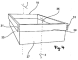
- FIG. 4 one of the drawers 19 of the drawer system 17 is shown in an enlarged detail view.
- the drawer 19 has at the upper edge region of a left and a right side wall 35 each have a U-shaped collar 31.
- a recessed grip 39 is provided at the upper edge region of a front side wall 37.
- the recessed grip 39 is in the Fig. 5 shown cross-sectional view of the drawer 19 shown again illustrated.
- drawers 19 By grasping the recessed grip 49 is each of the in the Fig. 1 shown drawers 19 simply slidable in the direction of the feed opening of the refrigerator. Likewise, the drawers 19 can be hung or unhooked on the respective hook elements 25 of the support plate 21.
- the intermediate bottom 11 separating the upper and middle cooling compartments 13 is then raised or tilted in the direction of the arrow I shown on its enclosure facing the left side wall 3 until a lead-through gap between the edge enclosure 23 and the side wall 3 is sufficiently large To guide support plate 21 through the feed-through gap down into the central cooling compartment 13.
- the support plate 21 is suspended by means of the support flange 22 on the enclosure 23 of the intermediate floor 11 and the raised intermediate bottom 11 again put the support projections 15.
- the support plate 21 can be variably mounted on the right or left side of a false floor 11 in the refrigerator 1.
Landscapes
- Engineering & Computer Science (AREA)
- Chemical & Material Sciences (AREA)
- Combustion & Propulsion (AREA)
- Physics & Mathematics (AREA)
- Mechanical Engineering (AREA)
- Thermal Sciences (AREA)
- General Engineering & Computer Science (AREA)
- Refrigerator Housings (AREA)
- Devices That Are Associated With Refrigeration Equipment (AREA)
Description
- Die Erfindung betrifft ein Kältegerät, insbesondere Haushaltskältegerät, mit einem Kühlraum, in dem zumindest ein Kühlgutträger gehaltert ist sowie eine Ablageanordnung für ein Kältegerät.
- Im Kühlraum eines Kältegerätes sind Ablagemöglichkeiten für unterschiedliche Lebensmittel vorgesehen. Lebensmittel, die sich nicht stapeln oder anderweitig sortieren lassen, können insbesondere in diversen kleineren Fächern gelagert sein. Zur Bildung dieser kleineren Fächer kann üblicherweise ein groß dimensionierter Kühlgutträger mittels eines Raumteilers in kleinere Segmente aufgeteilt werden.
- Aus der
US 5 626 407 A ist ein gattungsgemäßes Kältegerät bekannt, das innerhalb des Kühlraums eine Tragplatte mit einem Hakenelement aufweist, das nach unten offen ist. Geringfügig vom Hakenelement nach unten beabstandet ist ein Stützelement vorgesehen. Das Hakenelement bildet zusammen mit dem Stützelement ein im Querschnitt nahezu geschlossenes Hohlprofil, in das ein Kühlgutträger eingehängt werden kann. Aus derWO 89/08036 A1 WO 93/21487 A1 - Die Aufgabe der Erfindung besteht darin, ein Kältegerät mit baulich einfach gestalteten Ablagemöglichkeiten für insbesondere nicht stapelbare oder sortierbare Lebensmittel bereitzustellen.
- Die Aufgabe ist durch die Merkmale des Patentanspruches 1 gelöst. Bevorzugte Weiterbildungen der Erfindung sind in den Unteransprüchen offenbart.
- Unter Kältegerät wird hier insbesondere ein Haushaltskältegerät verstanden, wie beispielsweise ein Kühlschrank, ein Gefrierschrank oder eine Kühlgefrierkombination.
- Das Kältegerät weist einen Kühlraum auf, in dem zumindest ein Kühlgutträger gehaltert ist. Erfindungsgemäß ist in dem Kühlraum des Kältegerätes zumindest ein Tragelement vorgesehen, an dem der jeweilige Kühlgutträger einseitig eingehängt ist. Das Tragelement ist insbesondere einer der Begrenzungswände, etwa einer Seitenwand, des Kühlraumes zugeordnet. Auf diese Weise kann eine baulich einfache sowie raumsparende Ablageanordnung im Kühlraum des Kühlgerätes bereitgestellt werden, bei dem der Kühlgutbehälter in einfacher Weise ein- und aushängbar ist.
- Bevorzugt kann die so gebildete Ablageanordnung als eine separate Baueinheit im Kältegerät nachgerüstet werden. Die Ablageanordnung kann beispielhaft als ein Schubladensystem oder Ablagesystem nachträglich in den Kühlraum eingebaut werden.
- Für eine einfache Handhabung kann das Ablage- oder Schubladensystem werkzeugfrei lösbar im Kühlraum gehaltert sein. Auf diese Weise kann es zur Reinigung ohne weiteres aus dem Kühlgerät herausgenommen und anschließend wieder darin eingebaut werden.
- Die am Tragelement einhängbaren Kühlgutträger sind insbesondere für nicht stapelbare bzw. sortierbare Lebensmittel verwendbar. Solche Lebensmittel finden in den bevorzugt klein gestalteten Kühlgutträgern geordnet Platz. Die Kühlgutträger können separat zueinander herausgenommen sowie verstaut werden, so dass diese auch für den Transport der Lebensmittel geeignet sind.
- Der Kühlraum eines Kältegerätes kann mittels horizontaler Zwischenböden in übereinander angeordnete, voneinander separate Kühlfächer unterteilt sein. Bevorzugt kann das Tragelement zum Einhängen der Kühlgutträger in einem dieser Kühlfächer integriert sein, während die verbleibenden anderen Kühlfächer ohne einem solchen Tragelement vorgesehen werden können.
- Das erfindungsgemäße Ablagesystem kann eine Anzahl von Kühlgutträgern aufweisen, die insbesondere in unterschiedlichen Höhenpositionen, voneinander unabhängig am Tragelement eingehängt werden können.
- In einer technischen Ausführung der Erfindung kann das Tragelement der Ablageanordnung eine Tragplatte sein, die in Einbaulage hochkant sowie gegebenenfalls in flächiger Anlage mit einer Begrenzungswand, insbesondere einer Seitenwand, des Kältegerätes ist. Das Tragelement ist in diesem Fall bevorzugt als ein gegenüber den Begrenzungswänden des Kältegerätes separates Bauteil ausgebildet. Das Tragelement kann dabei unmittelbar an der Begrenzungswand befestigt sein. Alternativ dazu ist es jedoch bevorzugt, wenn das Tragelement werkzeugfrei lösbar im Kühlraum vorgesehen ist. In einer Ausführungsvariante kann das Tragelement an einem der Zwischenböden aufgehängt sein. Hierzu kann das Tragelement an seiner Oberseite einen abgewinkelten Halteschenkel aufweisen, der den Zwischenboden randseitig übergreifen kann und auf diesem abgestützt ist.
- Zum einseitigen Einhängen des Kühlgutträgers weist das Tragelement ein Hakenelement auf. Für eine sichere Halterung des Kühlgutträgers kann das Hakenelement leistenförmig langgestreckt sein. In Einbaulage kann sich das Hakenelement insbesondere in horizontaler Ebene entlang der Tragplatte erstrecken.
- Das Hakenelement weist einen in den Kühlraum abragenden Verbindungssteg auf, der in einen hochgezogenen Randflansch übergeht. Zur Halterung eines Kühlgutträgers kann dessen Einhängeabschnitt den Randflansch hintergreifen. Zur Festlegung einer Höhenposition des Kühlgutträgers ist dessen Einhängeabschnitt unmittelbar auf dem Verbindungssteg des Hakenelementes abgestützt.
- Der Randflansch des Hakenelementes kann über einen nach oben offenen freien Einführspalt von einer Grundebene der Tragplatte beabstandet sein. Bevorzugt ist der Einhängeabschnitt des Kühlgutträgers mit Spiel in dem Einführspalt eingehängt. Auf diese Weise kann der Kühlgutträger nach Art einer Schublade in Längsrichtung des leistenförmigen Hakenelementes leichtgängig verschoben werden.
- Dem Hakenelement ist zumindest ein Kippanschlag zugeordnet. Der Kippanschlag ist in Einbaulage des Tragelementes unterhalb seines Hakenelementes vorgesehen und zwischen das Tragelement und dem Kühlgutträger geschaltet. Mit Hilfe des Kippanschlages kann eine Winkellage des eingehängten Kühlgutträgers festgelegt werden. Der Kippanschlag ist unmittelbar am Tragelement ausgebildet.
- Das Tragelement ist aus einer Blechplatine hergestellt. Das Hakenelement und der Kippanschlag sind materialeinheitlich und einstückig durch Schneid- bzw. Umformvorgänge ausgebildet.
- Nachfolgend ist ein Ausführungsbeispiel der Erfindung anhand der beigefügten Figuren beschrieben.
- Es zeigen:
- Fig. 1
- in einer Teilschnittansicht den Kühlraum eines Kältegerätes mit eingebautem Schubfachsystem;
- Fig. 2
- in einer vergrößerten Detailansicht das Schubfachsystem aus der
Fig. 1 ; - Fig. 3
- in einer perspektivischen Ansicht ein Tragelement des Schubfachsystems;
- Fig. 4
- in einer perspektivischen Ansicht einen Kühlgutträger des Schubfachsystems; und
- Fig. 5
- eine Schnittdarstellung entlang der Schnittebene I-I aus der
Fig. 4 . - In der
Fig. 1 ist ein Kältegerät mit einem Kühlraum 1 gezeigt, welcher in Geräteseitenrichtung y durch gegenüberliegende Seitenwände 3 sowie in Bautiefenrichtung durch eine Rückwand 4 begrenzt ist. Die Wände 3,4 sind in bekannter Weise wärmeisolierend mit einer Innen- und einer Außenverkleidung sowie mit zwischengeschalteter Wärmeisolierung aufgebaut. Der Kühlraum 1 ist mittels horizontaler Zwischenböden 11 in übereinander angeordnete Kühlfächer 13 unterteilt. Die Zwischenböden 11 sind hierbei randseitig auf Stützvorsprüngen 15 abgestützt, die in der Innenverkleidung der Seitenwände 3 integriert sind. - Wie aus der
Fig. 1 hervorgeht, ist im gezeigten mittleren Kühlfach 13 ein Schubfachsystem 17 angeordnet. Das Schubfachsystem 17 weist drei Schubfächer 19 auf, die an einer Tragplatte 21 gehaltert sind. Die Tragplatte 21 ist hochkant angeordnet sowie vollflächig in Anlage mit der linken Seitenwand 3 des Kühlraumes 1. Die Tragplatte 21 des Schubfachsystems 17 ist in derFig. 3 in Alleinstellung gezeigt. Die Schubfächer 19 sind dabei in unterschiedlichen Höhenpositionen einseitig an der Tragplatte 21 eingehängt und so dimensioniert, dass sie lediglich die in derFig. 1 gezeigte linke Raumhälfte des Kühlfaches 13 einnehmen. - In der
Fig. 3 ist die Tragplatte 21 in Alleinstellung gezeigt. Die Tragplatte 21 ist aus einer Edelstahl-Blechplatine durch Schneid- bzw. Umformvorgänge hergestellt. Am oberen Ende der Tragplatte 21 ist ein Tragflansch 22 mit einem Anstellwinkel von 90° abgebogen. In Einbaulage gemäß derFig. 2 übergreift der Tragflansch 22 eine randseitige Einfassung 23 des Zwischenbodens 11 und ist auf dieser abgestützt. - Die Tragplatte 21 des Schubfachsystems 17 weist außerdem drei im Abstand übereinander angeordnete leistenförmige Hakenelemente 25 auf. Diese sind jeweils als streifenförmige Blechabschnitte aus einer Grundebene der Blechplatine unter Bildung von nach oben offener langgestreckter Einführspalte a herausgebogen. Die leistenförmigen Hakenelemente 25 erstrecken sich in Einbaulage des Schubfachsystems 17 parallel zueinander sowie in der Bautiefenrichtung des Kühlraumes 1. Jedes der Hakenelemente 25 ist aus einem Verbindungssteg 27 und einem hochgezogenen Randflansch 29 gebildet ist. Der Verbindungssteg 27 ist mit einem Biegewinkel von etwa 90° aus der Ebene der Tragplatte 21 herausgebogen und geht in den hochgezogenen Randflansch 29 über.
- Unterhalb eines jeden der Hakenelemente 25 sind gemäß der
Fig. 3 zwei in Bautiefenrichtung voneinander beabstandete Kippanschläge 30 ausgebildet, die als Blechlaschen aus der Blechplatine herausgebogen sind. - Die
Fig. 1 und2 zeigen das Schubfachsystem 17 in Einbaulage mit in der Tragplatte 17 eingehängten Schubfächern 19. Jedes der Schubfächer 19 ist mit einem Einhängeabschnitt 31 in ein Hakenelement 25 an der Tragplatte 21 eingehängt. - Gemäß der
Fig. 2 ist der Einhängeabschnitt 31 durch einen am oberen Rand des Schubfaches 19 angeordneten bodenseitig offenen U-förmigen Bund gebildet. Das eingehängte Schubfach 19 hintergreift mit dem U-förmigen Bund 31 den Randflansch 29 des Hakenelements 25. Die untere Anlagekante 32 des Bundes 31 ist dabei unmittelbar auf den in etwa horizontal abgebogenen Verbindungssteg 27 des Hakenelementes 25 der Tragplatte 21 abgestützt. In einer weiteren, nicht dargestellten Ausgestaltung der Erfindung kann anstelle dessen die obere Anlagekante 34 des Randflansches 29 auf dem Einhängeabschnitt 31 abgestützt sein. - Wie bereits erwähnt, ist der Randflansch 29 des Hakenelementes 25 über den freien Einführspalt a von der Grundebene der Tragplatte 21 beabstandet. Der Einführspalt a ist so bemessen, dass der U-förmige Bund 31 des Schubfaches 19 mit Bewegungsluft in dem Einführspalt a eingehängt ist. Auf diese Weise ist das Schubfach 19 leichtgängig in der Bautiefenrichtung entlang des leistenförmigen Hakenelements 25 verschiebbar.
- Ferner ist in der
Fig. 2 gezeigt, dass mit Hilfe des Kippanschlages 30 eine in etwa horizontale Winkellage des eingehängten Schubfaches 19 festgelegt ist. Im dargestellten Ausführungsbeispiel der Tragplatte 21 ergibt sich daher bedingt durch den Kippanschlag 30 eine horizontale Ausrichtung des Schubfachs 19. - In der
Fig. 4 ist eines der Schubfächer 19 des Schubfachsystems 17 in einer vergrößerten Detailansicht gezeigt. Das Schubfach 19 weist am oberen Randbereich einer linken sowie einer rechten Seitenwand 35 jeweils einen U-förmigen Bund 31 auf. Am oberen Randbereich einer vorderen Seitenwand 37 ist eine Griffmulde 39 vorgesehen. Die Griffmulde 39 ist in derFig. 5 gezeigten Querschnittansicht des Schubfachs 19 nochmals verdeutlicht dargestellt. - Durch Untergreifen der Griffmulde 49 ist jedes der in der
Fig. 1 gezeigten Schubfächer 19 einfach in Richtung der Beschickungsöffnung des Kühlgeräts verschiebbar. Ebenso einfach können die Schubfächer 19 an den jeweiligen Hakenelementen 25 der Tragplatte 21 eingehängt oder ausgehängt werden. - Nachfolgend ist die Montage des Schubfachsystems 17 in das gemäß der
Fig. 1 und2 mittlere Kühlfach 13 beschrieben. Demzufolge wird zunächst nur die Tragplatte 21 ohne eingehängte Schubfächer 19 im darüber angeordneten oberen Kühlfach 13 in Anlage mit einer der Seitenwände 3 gebracht. Um die in denFig. 1 und2 gezeigte Einbaulage zu erreichen, wird die Tragplatte 21 mit der linken Seitenwand 3 in Anlage gebracht. - Der das obere und mittlere Kühlfach 13 trennende Zwischenboden 11 wird dann in der gezeigten Pfeilrichtung I an seiner der linken Seitenwand 3 zugewandten Einfassung 23 so weit angehoben bzw. gekippt, bis ein Durchführungsspalt zwischen der Randeinfassung 23 und der Seitenwand 3 ausreichend groß ist, um die Tragplatte 21 durch den Durchführungsspalt nach unten in das mittlere Kühlfach 13 zu führen.
- Anschließend wird die Tragplatte 21 mittels des Tragflansches 22 an der Einfassung 23 des Zwischenbodens 11 eingehängt und der angehobene Zwischenboden 11 wieder auf die Stützvorsprünge 15 gelegt. Auf diese Weise kann die Tragplatte 21 variierbar an der rechten oder linken Seite eines Zwischenbodens 11 im Kühlraum 1 eingehängt werden.
-
- 1
- Kühlraum
- 3
- Seitenwand
- 5
- Isolationsschicht
- 11
- Zwischenböden
- 13
- Kühlfach
- 15
- Stützvorsprung
- 17
- Schubfachsystem
- 19
- Kühlgutträger, Schubfach
- 21
- Tragelement, Tragplatte
- 22
- Tragflansch
- 23
- Einfassung
- 25
- Hakenelement
- 27
- Verbindungssteg
- 29
- Randflansch
- 30
- Kippanschlag
- 31
- Einhängeabschnitt, U-förmiger Bund
- 32, 34
- Anlagekante
- 35
- linke, rechte Seitenwand
- 37
- vordere Seitenwand
- 39
- Griffmulde
- a
- Einführspalt
- y
- Geräteseitenrichtung
- I-I
- Schnittebene
- I
- Pfeilrichtung
Claims (9)
- Kältegerät, insbesondere Haushaltskältegerät, mit einem Kühlraum (1), in dem zumindest ein Kühlgutträger (19) gehaltert ist, wobei im Kühlraum (1) zumindest ein Tragelement (21) vorgesehen ist, das zumindest ein Hakenelement (25) aufweist, an dem der Kühlgutträger (19) mit einem Einhängeabschnitt (31) einseitig eingehängt ist, dadurch gekennzeichnet, dass das Hakenelement (25) einen in den Kühlraum (1) abragenden Verbindungssteg (27) aufweist, der in einen hochgezogenen Randflansch (29) übergeht, den der Einhängeabschnitt (31) des Kühlgutträgers (19) in Einbaulage hintergreift, und dass der Einhängeabschnitt (31) des Kühlgutträgers (19) eine Anlagekante (32) aufweist, mit der der Einhängeabschnitt (31) in Einbaulage auf dem Verbindungssteg (27) des Hakenelements (25) abgestützt ist, und dass dem Hakenelement (25) zumindest ein Kippanschlag (30) zugeordnet ist, der in Einbaulage unterhalb des Hakenelements (25) vorgesehen ist und zwischen das Tragelement (21) und dem Kühlgutträger (19) geschaltet ist und mit dem eine Winkellage des eingehängten Kühlgutträgers (19) festgelegt ist, und dass das Tragelement (21) aus einer Blechplatine hergestellt ist, in der das Hakenelement (25) und der Kippanschlag (30) durch Umformen ausgebildet sind.
- Kältegerät nach Anspruch 1, dadurch gekennzeichnet, dass der Kühlraum (1) mittels horizontaler Zwischenböden (11) in Kühlfächer (13) aufgeteilt ist, und in zumindest einem der Kühlfächer (13) das Tragelement (21) zum Einhängen des Kühlgutträgers (19) angeordnet ist.
- Kältegerät nach Anspruch 1 oder 2, dadurch gekennzeichnet, dass eine Anzahl von Kühlgutträgern (19), insbesondere in unterschiedlichen Höhenpositionen, voneinander unabhängig am Tragelement (21) einhängbar ist.
- Kältegerät nach Anspruch 1, 2 oder 3, dadurch gekennzeichnet, dass das Tragelement (21) zusammen mit dem zumindest einen Kühlgutträger (19) ein Ablagesystem (17), insbesondere ein Schubladensystem bildet, das als separate Baueinheit im Kühlraum (1) nachrüstbar ist.
- Kältegerät nach einem der vorhergehenden Ansprüche, dadurch gekennzeichnet, dass der Kühlgutträger (19) in einer Auszugrichtung verschiebbar am Tragelement (21) eingehängt ist.
- Kältegerät nach einem der vorhergehenden Ansprüche, dadurch gekennzeichnet, dass das Tragelement (21) als eine Tragplatte ausgebildet ist, die in Einbaulage hochkant angeordnet und insbesondere in Anlage mit einer Begrenzungswand (3) des Kühlraums (1) ist.
- Kältegerät nach einem der Ansprüche 1 bis 6, dadurch gekennzeichnet, dass das Hakenelement (25) leistenförmig ausgebildet ist, und sich in Einbaulage des Tragelements (21) insbesondere in horizontaler Ebene erstreckt.
- Kältegerät nach einem der vorhergehenden Ansprüche, dadurch gekennzeichnet, dass das Hakenelement (25) einen freien Einführspalt (a) begrenzt, in den der Einhängeabschnitt (31) des Kühlgutträgers (19) mit Spiel einhängbar ist.
- Kältegerät nach einem der vorhergehenden Ansprüche, dadurch gekennzeichnet, dass das Tragelement (21) für den zumindest einen Kühlgutträger (19) werkzeugfrei lösbar im Kühlraum (1) gehaltert ist, insbesondere an einem Zwischenboden (11) aufgehängt ist.
Applications Claiming Priority (2)
| Application Number | Priority Date | Filing Date | Title |
|---|---|---|---|
| DE102009002059.4A DE102009002059B4 (de) | 2009-03-31 | 2009-03-31 | Kältegerät, insbesondere Haushaltskältegerät, sowie Ablageanordnung hierfür |
| PCT/EP2010/052812 WO2010112296A2 (de) | 2009-03-31 | 2010-03-05 | Kältegerät, insbesondere haushaltskältegerät, sowie ablageanordnung hierfür |
Publications (2)
| Publication Number | Publication Date |
|---|---|
| EP2414755A2 EP2414755A2 (de) | 2012-02-08 |
| EP2414755B1 true EP2414755B1 (de) | 2016-09-14 |
Family
ID=42732926
Family Applications (1)
| Application Number | Title | Priority Date | Filing Date |
|---|---|---|---|
| EP10707031.0A Active EP2414755B1 (de) | 2009-03-31 | 2010-03-05 | Kältegerät, insbesondere haushaltskältegerät, sowie ablageanordnung hierfür |
Country Status (4)
| Country | Link |
|---|---|
| EP (1) | EP2414755B1 (de) |
| DE (1) | DE102009002059B4 (de) |
| PL (1) | PL2414755T3 (de) |
| WO (1) | WO2010112296A2 (de) |
Cited By (1)
| Publication number | Priority date | Publication date | Assignee | Title |
|---|---|---|---|---|
| EP4086548A1 (de) * | 2021-05-03 | 2022-11-09 | BSH Hausgeräte GmbH | Ablageanordnung mit einer profilschiene aus metall, sowie haushaltskältegerät |
Families Citing this family (9)
| Publication number | Priority date | Publication date | Assignee | Title |
|---|---|---|---|---|
| DE102011077370B4 (de) | 2011-06-10 | 2025-06-26 | BSH Hausgeräte GmbH | Ablageanordnung für ein Kältegerät |
| DE102011077371A1 (de) | 2011-06-10 | 2012-12-13 | BSH Bosch und Siemens Hausgeräte GmbH | Ablageanordnung für ein Kältegerät |
| US9389012B2 (en) | 2013-06-05 | 2016-07-12 | Electrolux Home Products, Inc. | Rail door bin system |
| DE102013225087A1 (de) * | 2013-12-06 | 2015-06-11 | BSH Hausgeräte GmbH | Haushaltskältegerät mit einer Verschiebekufe für einen darauf aufsetzbaren Behälter für Lebensmittel |
| WO2016134987A1 (en) * | 2015-02-27 | 2016-09-01 | Electrolux Appliances Aktiebolag | Refrigerating apparatus comprising a support panel |
| DE102017107118A1 (de) * | 2017-04-03 | 2018-10-04 | Michael Welle | Aufbewahrungsvorrichtung |
| US10451338B2 (en) | 2017-12-08 | 2019-10-22 | Electrolux Home Products, Inc. | Door storage bin assembly for a refrigerator |
| EP3963273A1 (de) * | 2019-05-03 | 2022-03-09 | Electrolux Do Brasil S.A. | Kühlschrank |
| DE102020211570A1 (de) | 2020-09-15 | 2022-03-17 | BSH Hausgeräte GmbH | Einhängevorrichtung für einen Lebensmittel-Aufnahmebehälter mit einer Profilschiene aus Metall, Anordnung sowie Haushaltskältegerätbauteil |
Family Cites Families (11)
| Publication number | Priority date | Publication date | Assignee | Title |
|---|---|---|---|---|
| US2002339A (en) * | 1933-12-23 | 1935-05-21 | Lloyd G Copeman | Refrigerator structure |
| US2089359A (en) * | 1934-08-03 | 1937-08-10 | Kelvinator Corp | Refrigerating apparatus |
| US4401222A (en) * | 1981-06-08 | 1983-08-30 | Westinghouse Electric Corp. | Support rail |
| JPS59105995U (ja) * | 1983-01-06 | 1984-07-17 | 日本建鐵株式会社 | 冷凍冷蔵オ−プンシヨ−ケ−ス |
| JPS6152182U (de) * | 1984-09-12 | 1986-04-08 | ||
| BR9201547A (pt) * | 1992-04-22 | 1993-10-26 | Consul Sa | Painel interno para porta de gabinete |
| US5397006A (en) * | 1993-06-22 | 1995-03-14 | Terrell; William H. | Storage tray system |
| US5626407A (en) * | 1996-05-10 | 1997-05-06 | Emplast, Inc. | Storage system for refrigerators |
| WO1998008036A1 (de) * | 1996-08-22 | 1998-02-26 | Bosch-Siemens Hausgeräte Gmbh | Kühlschranktür |
| DE202004016966U1 (de) * | 2004-11-03 | 2006-03-16 | Liebherr-Hausgeräte Lienz Gmbh | Kühl- und/oder Gefriergutbehältnis |
| WO2006090342A1 (en) * | 2005-02-28 | 2006-08-31 | Arcelik Anonim Sirketi | A cooling device |
-
2009
- 2009-03-31 DE DE102009002059.4A patent/DE102009002059B4/de active Active
-
2010
- 2010-03-05 EP EP10707031.0A patent/EP2414755B1/de active Active
- 2010-03-05 PL PL10707031T patent/PL2414755T3/pl unknown
- 2010-03-05 WO PCT/EP2010/052812 patent/WO2010112296A2/de not_active Ceased
Cited By (1)
| Publication number | Priority date | Publication date | Assignee | Title |
|---|---|---|---|---|
| EP4086548A1 (de) * | 2021-05-03 | 2022-11-09 | BSH Hausgeräte GmbH | Ablageanordnung mit einer profilschiene aus metall, sowie haushaltskältegerät |
Also Published As
| Publication number | Publication date |
|---|---|
| EP2414755A2 (de) | 2012-02-08 |
| DE102009002059A1 (de) | 2010-10-14 |
| WO2010112296A3 (de) | 2011-01-13 |
| DE102009002059B4 (de) | 2017-07-20 |
| PL2414755T3 (pl) | 2017-02-28 |
| WO2010112296A2 (de) | 2010-10-07 |
Similar Documents
| Publication | Publication Date | Title |
|---|---|---|
| DE102009002059B4 (de) | Kältegerät, insbesondere Haushaltskältegerät, sowie Ablageanordnung hierfür | |
| EP1306622B1 (de) | Schienensystem für Gargutträger in einem Backofen | |
| WO2010112293A2 (de) | Haushaltskältegerät | |
| WO2005026635A1 (de) | Fachboden für ein kältegerät | |
| EP2464933B1 (de) | Kältegerät mit einer linear geführten auszugsplatte, insbesondere glasplatte und einer halteanordnung für wenigstens einen behälter | |
| EP2567165A1 (de) | Ablagesystem für ein kältegerät mit wenigstens einer horizontal schwenkbaren ablageschale | |
| EP1717519A2 (de) | Garofenmuffel | |
| EP2913610A1 (de) | Haushaltskältegerät mit einem Fachboden und einer am Fachboden gelagerten Haltevorrichtung | |
| EP2218994B1 (de) | Kältegerät mit ausziehbare Abstellplatten untergreifenden Auflagern | |
| EP2235457A1 (de) | Kältegerät | |
| EP2005093B1 (de) | Kältegerät mit abstellplatte | |
| EP3163233B1 (de) | Haushaltskältegerät | |
| DE102015005666A1 (de) | Türanordnung für Kühlvitrine | |
| DE202014000325U1 (de) | Vorrichtung zur Präsentation und Ausgabe von Waren, insbesondere Backwaren | |
| EP2187785B1 (de) | Vorsatzsystem für ein warenpräsentationssystem | |
| DE102009028418A1 (de) | Kältegerät | |
| DE102011077370B4 (de) | Ablageanordnung für ein Kältegerät | |
| EP2512296B1 (de) | Warentheke | |
| DE102005021848A1 (de) | Kühl- und/oder Gefriergerät | |
| EP1660826B1 (de) | Kältegerät | |
| EP3805676A1 (de) | Haushaltsgerät mit spezifischer lagervorrichtung mit einer balkenartigen lagerrinne für einen schienenauszug | |
| DE102009045057B4 (de) | Kältegerät, insbesondere Haushaltskältegerät, sowie Einhängeleiste für ein solches Klimagerät | |
| DE202015003240U1 (de) | Türanordnung für Kühlvitrine | |
| EP0608699B1 (de) | Kühlgerät | |
| DE10241489A1 (de) | Teleskopartiges System und Auszug für einen Gargutträger |
Legal Events
| Date | Code | Title | Description |
|---|---|---|---|
| PUAI | Public reference made under article 153(3) epc to a published international application that has entered the european phase |
Free format text: ORIGINAL CODE: 0009012 |
|
| 17P | Request for examination filed |
Effective date: 20111031 |
|
| AK | Designated contracting states |
Kind code of ref document: A2 Designated state(s): AT BE BG CH CY CZ DE DK EE ES FI FR GB GR HR HU IE IS IT LI LT LU LV MC MK MT NL NO PL PT RO SE SI SK SM TR |
|
| DAX | Request for extension of the european patent (deleted) | ||
| RAP1 | Party data changed (applicant data changed or rights of an application transferred) |
Owner name: BSH HAUSGERAETE GMBH |
|
| RIC1 | Information provided on ipc code assigned before grant |
Ipc: F25D 25/02 20060101ALI20160421BHEP Ipc: F25D 23/06 20060101AFI20160421BHEP |
|
| GRAP | Despatch of communication of intention to grant a patent |
Free format text: ORIGINAL CODE: EPIDOSNIGR1 |
|
| INTG | Intention to grant announced |
Effective date: 20160601 |
|
| GRAS | Grant fee paid |
Free format text: ORIGINAL CODE: EPIDOSNIGR3 |
|
| GRAA | (expected) grant |
Free format text: ORIGINAL CODE: 0009210 |
|
| AK | Designated contracting states |
Kind code of ref document: B1 Designated state(s): AT BE BG CH CY CZ DE DK EE ES FI FR GB GR HR HU IE IS IT LI LT LU LV MC MK MT NL NO PL PT RO SE SI SK SM TR |
|
| REG | Reference to a national code |
Ref country code: GB Ref legal event code: FG4D Free format text: NOT ENGLISH |
|
| REG | Reference to a national code |
Ref country code: CH Ref legal event code: EP |
|
| REG | Reference to a national code |
Ref country code: IE Ref legal event code: FG4D Free format text: LANGUAGE OF EP DOCUMENT: GERMAN |
|
| REG | Reference to a national code |
Ref country code: AT Ref legal event code: REF Ref document number: 829457 Country of ref document: AT Kind code of ref document: T Effective date: 20161015 |
|
| REG | Reference to a national code |
Ref country code: DE Ref legal event code: R096 Ref document number: 502010012401 Country of ref document: DE |
|
| REG | Reference to a national code |
Ref country code: LT Ref legal event code: MG4D |
|
| REG | Reference to a national code |
Ref country code: NL Ref legal event code: MP Effective date: 20160914 |
|
| PG25 | Lapsed in a contracting state [announced via postgrant information from national office to epo] |
Ref country code: HR Free format text: LAPSE BECAUSE OF FAILURE TO SUBMIT A TRANSLATION OF THE DESCRIPTION OR TO PAY THE FEE WITHIN THE PRESCRIBED TIME-LIMIT Effective date: 20160914 Ref country code: NO Free format text: LAPSE BECAUSE OF FAILURE TO SUBMIT A TRANSLATION OF THE DESCRIPTION OR TO PAY THE FEE WITHIN THE PRESCRIBED TIME-LIMIT Effective date: 20161214 Ref country code: FI Free format text: LAPSE BECAUSE OF FAILURE TO SUBMIT A TRANSLATION OF THE DESCRIPTION OR TO PAY THE FEE WITHIN THE PRESCRIBED TIME-LIMIT Effective date: 20160914 Ref country code: LT Free format text: LAPSE BECAUSE OF FAILURE TO SUBMIT A TRANSLATION OF THE DESCRIPTION OR TO PAY THE FEE WITHIN THE PRESCRIBED TIME-LIMIT Effective date: 20160914 |
|
| PG25 | Lapsed in a contracting state [announced via postgrant information from national office to epo] |
Ref country code: SE Free format text: LAPSE BECAUSE OF FAILURE TO SUBMIT A TRANSLATION OF THE DESCRIPTION OR TO PAY THE FEE WITHIN THE PRESCRIBED TIME-LIMIT Effective date: 20160914 Ref country code: LV Free format text: LAPSE BECAUSE OF FAILURE TO SUBMIT A TRANSLATION OF THE DESCRIPTION OR TO PAY THE FEE WITHIN THE PRESCRIBED TIME-LIMIT Effective date: 20160914 Ref country code: GR Free format text: LAPSE BECAUSE OF FAILURE TO SUBMIT A TRANSLATION OF THE DESCRIPTION OR TO PAY THE FEE WITHIN THE PRESCRIBED TIME-LIMIT Effective date: 20161215 Ref country code: NL Free format text: LAPSE BECAUSE OF FAILURE TO SUBMIT A TRANSLATION OF THE DESCRIPTION OR TO PAY THE FEE WITHIN THE PRESCRIBED TIME-LIMIT Effective date: 20160914 |
|
| PG25 | Lapsed in a contracting state [announced via postgrant information from national office to epo] |
Ref country code: RO Free format text: LAPSE BECAUSE OF FAILURE TO SUBMIT A TRANSLATION OF THE DESCRIPTION OR TO PAY THE FEE WITHIN THE PRESCRIBED TIME-LIMIT Effective date: 20160914 Ref country code: EE Free format text: LAPSE BECAUSE OF FAILURE TO SUBMIT A TRANSLATION OF THE DESCRIPTION OR TO PAY THE FEE WITHIN THE PRESCRIBED TIME-LIMIT Effective date: 20160914 |
|
| PG25 | Lapsed in a contracting state [announced via postgrant information from national office to epo] |
Ref country code: PT Free format text: LAPSE BECAUSE OF FAILURE TO SUBMIT A TRANSLATION OF THE DESCRIPTION OR TO PAY THE FEE WITHIN THE PRESCRIBED TIME-LIMIT Effective date: 20170116 Ref country code: SM Free format text: LAPSE BECAUSE OF FAILURE TO SUBMIT A TRANSLATION OF THE DESCRIPTION OR TO PAY THE FEE WITHIN THE PRESCRIBED TIME-LIMIT Effective date: 20160914 Ref country code: SK Free format text: LAPSE BECAUSE OF FAILURE TO SUBMIT A TRANSLATION OF THE DESCRIPTION OR TO PAY THE FEE WITHIN THE PRESCRIBED TIME-LIMIT Effective date: 20160914 Ref country code: BG Free format text: LAPSE BECAUSE OF FAILURE TO SUBMIT A TRANSLATION OF THE DESCRIPTION OR TO PAY THE FEE WITHIN THE PRESCRIBED TIME-LIMIT Effective date: 20161214 Ref country code: IS Free format text: LAPSE BECAUSE OF FAILURE TO SUBMIT A TRANSLATION OF THE DESCRIPTION OR TO PAY THE FEE WITHIN THE PRESCRIBED TIME-LIMIT Effective date: 20170114 Ref country code: CZ Free format text: LAPSE BECAUSE OF FAILURE TO SUBMIT A TRANSLATION OF THE DESCRIPTION OR TO PAY THE FEE WITHIN THE PRESCRIBED TIME-LIMIT Effective date: 20160914 Ref country code: ES Free format text: LAPSE BECAUSE OF FAILURE TO SUBMIT A TRANSLATION OF THE DESCRIPTION OR TO PAY THE FEE WITHIN THE PRESCRIBED TIME-LIMIT Effective date: 20160914 |
|
| REG | Reference to a national code |
Ref country code: DE Ref legal event code: R097 Ref document number: 502010012401 Country of ref document: DE |
|
| PLBE | No opposition filed within time limit |
Free format text: ORIGINAL CODE: 0009261 |
|
| STAA | Information on the status of an ep patent application or granted ep patent |
Free format text: STATUS: NO OPPOSITION FILED WITHIN TIME LIMIT |
|
| PG25 | Lapsed in a contracting state [announced via postgrant information from national office to epo] |
Ref country code: DK Free format text: LAPSE BECAUSE OF FAILURE TO SUBMIT A TRANSLATION OF THE DESCRIPTION OR TO PAY THE FEE WITHIN THE PRESCRIBED TIME-LIMIT Effective date: 20160914 |
|
| 26N | No opposition filed |
Effective date: 20170615 |
|
| REG | Reference to a national code |
Ref country code: CH Ref legal event code: PL |
|
| GBPC | Gb: european patent ceased through non-payment of renewal fee |
Effective date: 20170305 |
|
| PG25 | Lapsed in a contracting state [announced via postgrant information from national office to epo] |
Ref country code: SI Free format text: LAPSE BECAUSE OF FAILURE TO SUBMIT A TRANSLATION OF THE DESCRIPTION OR TO PAY THE FEE WITHIN THE PRESCRIBED TIME-LIMIT Effective date: 20160914 Ref country code: MC Free format text: LAPSE BECAUSE OF FAILURE TO SUBMIT A TRANSLATION OF THE DESCRIPTION OR TO PAY THE FEE WITHIN THE PRESCRIBED TIME-LIMIT Effective date: 20160914 |
|
| REG | Reference to a national code |
Ref country code: IE Ref legal event code: MM4A |
|
| REG | Reference to a national code |
Ref country code: FR Ref legal event code: ST Effective date: 20171130 |
|
| PG25 | Lapsed in a contracting state [announced via postgrant information from national office to epo] |
Ref country code: LU Free format text: LAPSE BECAUSE OF NON-PAYMENT OF DUE FEES Effective date: 20170305 Ref country code: FR Free format text: LAPSE BECAUSE OF NON-PAYMENT OF DUE FEES Effective date: 20170331 |
|
| PG25 | Lapsed in a contracting state [announced via postgrant information from national office to epo] |
Ref country code: CH Free format text: LAPSE BECAUSE OF NON-PAYMENT OF DUE FEES Effective date: 20170331 Ref country code: IE Free format text: LAPSE BECAUSE OF NON-PAYMENT OF DUE FEES Effective date: 20170305 Ref country code: LI Free format text: LAPSE BECAUSE OF NON-PAYMENT OF DUE FEES Effective date: 20170331 Ref country code: GB Free format text: LAPSE BECAUSE OF NON-PAYMENT OF DUE FEES Effective date: 20170305 |
|
| REG | Reference to a national code |
Ref country code: BE Ref legal event code: MM Effective date: 20170331 |
|
| REG | Reference to a national code |
Ref country code: AT Ref legal event code: MM01 Ref document number: 829457 Country of ref document: AT Kind code of ref document: T Effective date: 20170305 |
|
| PG25 | Lapsed in a contracting state [announced via postgrant information from national office to epo] |
Ref country code: BE Free format text: LAPSE BECAUSE OF NON-PAYMENT OF DUE FEES Effective date: 20170331 |
|
| PG25 | Lapsed in a contracting state [announced via postgrant information from national office to epo] |
Ref country code: AT Free format text: LAPSE BECAUSE OF NON-PAYMENT OF DUE FEES Effective date: 20170305 |
|
| PG25 | Lapsed in a contracting state [announced via postgrant information from national office to epo] |
Ref country code: MT Free format text: LAPSE BECAUSE OF FAILURE TO SUBMIT A TRANSLATION OF THE DESCRIPTION OR TO PAY THE FEE WITHIN THE PRESCRIBED TIME-LIMIT Effective date: 20160914 |
|
| PG25 | Lapsed in a contracting state [announced via postgrant information from national office to epo] |
Ref country code: HU Free format text: LAPSE BECAUSE OF FAILURE TO SUBMIT A TRANSLATION OF THE DESCRIPTION OR TO PAY THE FEE WITHIN THE PRESCRIBED TIME-LIMIT; INVALID AB INITIO Effective date: 20100305 |
|
| PG25 | Lapsed in a contracting state [announced via postgrant information from national office to epo] |
Ref country code: CY Free format text: LAPSE BECAUSE OF NON-PAYMENT OF DUE FEES Effective date: 20160914 |
|
| PG25 | Lapsed in a contracting state [announced via postgrant information from national office to epo] |
Ref country code: MK Free format text: LAPSE BECAUSE OF FAILURE TO SUBMIT A TRANSLATION OF THE DESCRIPTION OR TO PAY THE FEE WITHIN THE PRESCRIBED TIME-LIMIT Effective date: 20160914 |
|
| REG | Reference to a national code |
Ref country code: DE Ref legal event code: R084 Ref document number: 502010012401 Country of ref document: DE |
|
| PGFP | Annual fee paid to national office [announced via postgrant information from national office to epo] |
Ref country code: IT Payment date: 20240329 Year of fee payment: 15 |
|
| PGFP | Annual fee paid to national office [announced via postgrant information from national office to epo] |
Ref country code: DE Payment date: 20250331 Year of fee payment: 16 |
|
| PGFP | Annual fee paid to national office [announced via postgrant information from national office to epo] |
Ref country code: PL Payment date: 20250224 Year of fee payment: 16 |
|
| PGFP | Annual fee paid to national office [announced via postgrant information from national office to epo] |
Ref country code: TR Payment date: 20250225 Year of fee payment: 16 |
|
| PG25 | Lapsed in a contracting state [announced via postgrant information from national office to epo] |
Ref country code: IT Free format text: LAPSE BECAUSE OF NON-PAYMENT OF DUE FEES Effective date: 20250305 |