EP2414242B1 - Dispositif d'avitaillement de propulseurs d'un lanceur - Google Patents
Dispositif d'avitaillement de propulseurs d'un lanceur Download PDFInfo
- Publication number
- EP2414242B1 EP2414242B1 EP10715987.3A EP10715987A EP2414242B1 EP 2414242 B1 EP2414242 B1 EP 2414242B1 EP 10715987 A EP10715987 A EP 10715987A EP 2414242 B1 EP2414242 B1 EP 2414242B1
- Authority
- EP
- European Patent Office
- Prior art keywords
- ground
- board
- valve
- plate
- passage
- Prior art date
- Legal status (The legal status is an assumption and is not a legal conclusion. Google has not performed a legal analysis and makes no representation as to the accuracy of the status listed.)
- Active
Links
Images


Classifications
-
- B—PERFORMING OPERATIONS; TRANSPORTING
- B64—AIRCRAFT; AVIATION; COSMONAUTICS
- B64G—COSMONAUTICS; VEHICLES OR EQUIPMENT THEREFOR
- B64G5/00—Ground equipment for vehicles, e.g. starting towers, fuelling arrangements
-
- B—PERFORMING OPERATIONS; TRANSPORTING
- B64—AIRCRAFT; AVIATION; COSMONAUTICS
- B64G—COSMONAUTICS; VEHICLES OR EQUIPMENT THEREFOR
- B64G1/00—Cosmonautic vehicles
- B64G1/22—Parts of, or equipment specially adapted for fitting in or to, cosmonautic vehicles
- B64G1/40—Arrangements or adaptations of propulsion systems
- B64G1/402—Propellant tanks; Feeding propellants
Definitions
- the invention relates to a device for refueling propellers, including cryogenic thrusters, a launcher for performing the separation of the filling pipe during takeoff launcher.
- Such a refueling device can fill propellant cryogenic propellants and this up to the moment of takeoff.
- This constraint causes a certain number of technical difficulties since the rupture of the pipeline connecting the ground to the launcher must be effective at the time of launch, and this without modifying the trajectory of the launcher or interfere with the equipment remaining on the ground or embarked on the cryogenic stage or other stages of the launcher.
- cryogenic arms equipped with valve plates are used.
- These flange / ground link plate plates allow the various filling and pressurization operations required for launch checks and preparations. It is a board plate and a floor plate equipped with valves or valves to close the hydraulic and pneumatic edge and ground (filling and bleeding / degassing).
- unlocking between the ground and edge plates is effected by means of unlocking cylinders which comprise two parts made movable with each other when the cylinder is pressurized. These parts being respectively fixed to the ground and edge plates, the latter deviate from one another during the pressurization of the unlocking cylinders. Then, because of the weight of the plates and the hoses attached to them and the pull exerted during the elevation of the launcher by a dedicated extraction cable, the floor and edge plates pivot about the axis of a hinge which connect them, until the disengagement of the latter, which leads to the separation of the ground and edge plates.
- Such a change of the edge / ground link includes the replacement of the valve plates and is accompanied by a complete reconfiguration of the propellant circuits including a drain, which takes a lot of time (about a week).
- the release operation of the cryogenic arms during launching is tricky: if the arm is retracted a little too late, without unbalancing the launcher, there is a risk of damage to the filling device at the same time installations on the ground and at the level of the installations on the launcher.
- the document US 5,404,923 relates to a device for the automatic refueling of a launcher.
- the document EP 0 146 684 refers to a pipe connection by a negative pressure difference between an enclosure and the outside.
- the document US 3,249,013 relates to a device for refueling thrusters of a launcher according to the preamble of claim 1.
- the object of the present invention is to provide a thruster refueling device of a launcher making it possible to overcome the drawbacks of the prior art and in particular to provide the possibility of reconnection in the event of aborted firing.
- the refueling device is characterized in that the ground module further comprises a ground valve connected to the ground channel, downstream of the latter, and to the ground passage, and in that the system hydraulic coupling between the edge module and the ground module further comprises a first annular enclosure located between the edge plate and the ground plate, around the hydraulic coupling system and whose depression allows the plate edge and the ground plate to be kept in a connected position.
- This solution also has the additional advantage of allowing, in addition, to maintain the connection between the edge module and the ground module by extremely simple and reliable means.
- Figures 1 to 3 schematically illustrating the principle of the invention with a refueling device 10 comprising a ground module 20, right in the figures, and an edge module 30, on the left in the figures.
- the soil modules 20 and edge 30 are in position connected to each other and the refueling circuit is open to allow the fluid supply of the tanks.
- the ground module 20 comprises, from upstream to downstream in the direction of the arrows representing the flow of the refueling fluid, a solenoid valve 21 housed or opening into a ground channel 22 placed upstream of a source of refueling fluid. (not shown), a ground control 24 and a floor plate 26 having a floor passage 28 towards the edge module 30.
- the ground control 24 is represented in the form of a jack with a piston 24a slidably movable in a cylinder 24b delimiting two chambers: a front chamber 24c connected to the ground channel 22 and a rear chamber 24d in which the piston head 24e is lodged.
- An opening 24f in the rear chamber 24d allows the entry into the latter of a gas under pressure, which allows the advance of the piston head 24e in a forward position, driving the piston rod 24g left on the figure 1 , up to the edge module 30, which places in the open position an edge valve 36, the valve 36a is previously in the closed position.
- the rear chamber 24d also comprises return means (here a coil spring 24) allowing the piston 24a to return to a rear position, which corresponds to a closed position of the edge valve 36 ( Figures 2 and 3 ) when the gas pressure decreases in the rear chamber 24d.
- return means here a coil spring 24
- the floor plate 26 surrounds the front portion of the cylinder 24b of the piston 24a by delimiting the floor passage 28 in the extension of the front chamber 24c.
- the edge module 30 comprises, from upstream to downstream in the direction of the arrows representing the flow of the refueling fluid (from right to left in the figures), an edge plate 32 delimiting a passage 34 which is, on the Figures 1 and 2 , in the extension of the ground passage 28, the edge valve 36 and an edge channel 38 connected to the cryogenic tanks.
- the edge valve 36 is shown in the form of a valve 36a or a valve capable of closing the edge passage 34, a portion of which forms the seat 36b of the edge valve 36, an O-ring 36c makes it possible to perfect the seal between the valve 36a and the seat 36b when the edge valve 36 is in the closed position ( Figure 3 ).
- Returning means (here a helical spring 36d) allow the return of the edge valve 36 in the closed position in which the edge passage 34 is no longer in fluid communication with the floor passage 28 ( figure 3 ).
- the opening / closing command of the solenoid valve 21 is independent of the opening / closing control of the edge valve 36.
- this alternative embodiment provides as a difference with respect to FIGS. Figures 1 to 3 , the fact that the solenoid valve 21 is housed in the front chamber 24c and is also controlled by the ground control 24.
- the solenoid valve 21 comprises an annular valve 21a mounted integrally around the piston rod 24g and a annular seat 21b mounted on the inner face of the cylinder wall 24b, the rear of the valve 21a.
- An o-ring 21c makes it possible to perfect the seal between the valve 21a and the seat 21b when the solenoid valve 21 is in the closed position ( Figures 2A and 3A ).
- the movement of the piston rod 24g forward (on the left of the Figures 1A to 3A ) allows, by moving forward both the valve 36a of the edge valve 36 and the valve 21a of the solenoid valve 21, simultaneously open the edge valve 36 and the solenoid valve 21.
- the opening control of the solenoid valve 21 causes the control to open the edge valve 36
- the closing command of the solenoid valve 21 causes the closing control of the edge valve 36
- FIG. 1A it has been shown figures 1 and 1A the case where the opening 24f opens into the rear part of the rear chamber 24d while the coil spring 24 is supported on the piston head 24e being housed in the front part of the rear chamber 24d, but we can reverse this arrangement (Opening 24f which opens into the front part of the rear chamber 24d and coil spring 24 housed in the rear part of the rear chamber 24d). It is also possible to use two openings which open respectively in the front part and in the rear part of the rear chamber 24d and which are capable of delivering gases under different pressures, whereby the piston head 24e can be advanced or retracted. and the piston rod 24g.
- the ground control 24 is reduced to the cylinder 24b delimiting a chamber A single, pistonless, connected to the ground channel 22.
- it is the pressure of the penetrating fluid through the ground channel that moves the valve 36a and open the valve edge 36.
- the solenoid valve (not shown) is located upstream of the hydraulic coupling system 40.
- the edge valve 36 is placed further downstream of the hydraulic coupling system 40: thus the solenoid valves 21 and edge 36 each have their own order.
- the ground module 20 and the edge module 30 are connected to each other by a hydraulic coupling system 40 which comprises an annular seal 40a allowing a seal between the ground module 20 and the edge module 30 (between the edge plate 32 and the floor plate 26).
- a first annular enclosure 50 capable of being depressed, surrounds the hydraulic coupling system 40.
- this first annular enclosure 50 extends between the floor plate 26 and the edge plate 32 (respectively to the right and to the left on the Figures 1 to 3 ).
- the first annular enclosure 50 is bounded in the outer radial direction by a first annular bellows 52 surrounding the hydraulic coupling system 40 and whose ends bear tightly against the edge plate 32 and the floor plate 26.
- the floor plate has an opening 54 opening into said first enclosure 50 and capable of being connected to means of depression (not shown).
- the ground plate 26 and the connected edge plate 32 are maintained by "suction effect", which makes it possible to keep the ground module 20 and the edge module 30 connected together (see FIG. Figures 1 and 2 , 1A and 1B, and 1C).
- the gas pressure has been increased in the first annular enclosure 50, by gas injection through the opening 54, so that the soil modules 20 and 30 edge are then disconnected and become separable from each other, for example when the elevation of the launcher.
- This increase of the gas pressure in the first annular enclosure 50 can be a setting to atmospheric pressure or a setting overpressure (pressure above atmospheric pressure).
- This embodiment comprises two parallel veins for supplying or emptying fluid, for example making it possible simultaneously to fill the cryogenic tanks with different propellants (chemical nature and / or different physical state), in particular a liquid propellant and a propellant. gaseous, for example on one side of the liquid oxygen and in parallel with the gaseous oxygen.
- propellants chemical nature and / or different physical state
- gaseous for example on one side of the liquid oxygen and in parallel with the gaseous oxygen.
- the two parallel fluid supply veins are coaxial.
- the first floor passage 28 1 and the second floor passage 28 2 on the one hand and the first edge passage 34 1 and the second edge passage 34 2 on the other hand are coaxial with respect to each other on at least one section of said passages 28 1 , 28 2 , 34 1 , 34 2 .
- the first ground assembly formed by the first ground channel 22 1 and the first ground valve 24 1 is located parallel to the side of the second ground assembly formed by the second ground channel 22 2 and the second ground valve 24 2 .
- This first ground assembly is mounted on the ground plate 26 at a first location forming the opening of the first floor passage 28 1 which is rectilinear to its output.
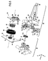
- This second ground assembly is mounted on the ground plate 26 at a second location forming the opening of the second floor passage 28 2 which has, successively in the extension of one another, a first portion 28 2 has rectilinear parallel to the X axis and the second channel 2 Basement 22, a second rectilinear portion 28 2 b substantially parallel to the axis Y which extends almost at right angles from the first portion 28 2a toward the first passage 1 and a ground 28 third annular portion 28 2c which extends to the outlet of the second passage 2 and ground 28 which surrounds the downstream portion of the first passage floor 28 1 (see figure 7 ).
- the first edge assembly formed by the first edge channel 38 1 and the first edge valve 36 1 is located parallel to the side of the second edge assembly formed by the second edge channel 38 2 and the second edge valve 36 2 .
- This first edge assembly is mounted on the edge plate 32 at a first location forming the opening of the first edge passage 34 1 which is rectilinear to its exit.
- This second edge assembly is mounted on the edge plate 32 at a second location forming the opening of the second passage edge 34 2 which has, successively in the extension of one another, a first portion 34 has two straight parallel to the X axis and the second edge channel 38 2, a second portion 34 b two straight substantially parallel to the Y axis which extends at an almost straight angle from the first portion 34 2 a towards the first edge passage 34 1 and a third portion 34 2 c annular extending to the exit of the second edge passage 34 2 and surrounding the downstream portion of the first edge passage 34 1 (see figure 7 ).
- a filter 35 is disposed inside the first edge passage 34 1 which is intended more particularly for the passage of a liquid, and this in order to avoid polluting with particles the fluid stream downstream of the refueling device 10.
- valves are ball valves.
- other types of valves such as flap valves can be envisaged.
- a threaded annular flange 33 receives by screwing a central annular cover 37 whose free end 37a turned in the opposite direction to the plate edge 32 is crenellated and flared.
- This free end 37a can receive, in the surrounding, a projecting annular portion 27 formed on the face of the ground plate 26 facing the edge module 30, this projecting annular portion 27 surrounding the downstream portion of the first passage ground 28 1 .
- the hydraulic coupling system 40 thus essentially comprises the annular flange 33 of the edge plate 32, the annular centering cover 37 and the projecting annular portion 27 of the floor plate 26.
- annular faces of the annular flange 33 and the central annular cover 37 are provided with an annular seal.
- a first annular enclosure 50 delimited radially on the outside by the first annular bellows 52 surrounds the hydraulic coupling system 40.
- the opening 54 of the ground plate is in the axial extension (along the X axis) of the first annular enclosure 50 and makes it possible, by connection with means for depressurizing (by For example, a pump) to depressurize the first annular enclosure 50.
- the end walls of the first annular bellows 52 which are covered with an annular seal are "glued" to the facing faces of the floor plates 26 and edge 32, which creates a sucker type connection.
- the refueling device 10 Figures 5 to 9 further comprises a second annular enclosure 60 adapted to be placed under an overpressure, located between the edge plate 32 and the ground plate 26, around the hydraulic coupling system 40 and around which the first annular enclosure 50 is located.
- This second annular enclosure 60 is defined radially on the outside by a second annular bellows 62 (see FIGS. Figures 4 to 6 ) which surrounds the hydraulic coupling system 40 and which is surrounded by the first annular bellows 52.
- the second annular enclosure 60 is pressurized by a dedicated supply (conduit 63 on the figure 6 ) which allows the introduction of a neutral gas overpressure through an opening of the floor plate 26: thus, it is avoided that dangerous products can not enter the vacuum zone.
- the overpressure hold of the second annular enclosure 60 does not compromise the holding in the connected position between the ground module 20 and the edge module 30 because the first annular enclosure 50 is outside the second annular enclosure 60 and has a sufficient size so that the depression inside the first annular enclosure maintains the coupling between the edge module 30 and the ground module 20.
- the overpressure of the second annular enclosure 60 allows, if necessary, to condition the hydraulic coupling system 40, namely by adding an anti-icing system in the form of a gas scan (dry air or nitrogen ) external to the first bellows 52 (leads 64 on the figure 6 ) to prevent the formation of ice, especially in the area of contact between the first bellows 52 and the edge plate 32.
- an anti-icing system in the form of a gas scan (dry air or nitrogen ) external to the first bellows 52 (leads 64 on the figure 6 ) to prevent the formation of ice, especially in the area of contact between the first bellows 52 and the edge plate 32.
- the refueling device 10 Figures 5 to 9 further comprises, between the edge plate 32 and the ground plate 26, a mechanical locking system 70 adapted to open during or before the elevation of the launcher.
- the mechanical locking system 70 comprises, on either side of the first annular enclosure 50, a release fork 72 whose lower end 72a bears on the edge plate 32 in the connected position, at the level of a receiving portion 39 on which bears the lower end 72a by complementary shape, while the upper end 72b of the release fork 72 is pivotally mounted about a ground axis 29 integral with the ground plate 26 of so that a rotation of the release fork 72 about the ground axis 29 causes a spacing between the ground plate 26 and the edge plate 32 or a cracking point on the structure on which the edge plate 32 is fixed (until at the moment when the lower end 72a leaves the receiving portion 39) and vice versa.
- the drop fork 72 is provided, between its lower end 72a and its upper end 72b, a hole for attaching a sling whose other end is fixed to the ground. In this way, during the elevation of the launcher, the ground module 20 is thus retained and separated from the edge module which is integral with the launcher.
- the mechanical locking system 70 further comprises, on either side of the first annular enclosure 50, a locking pin 74 (see FIG. figure 9 ) movable in rotation about the ground axis 29 between an open position (not shown) which does not hold between the ground plate 26 and the edge plate 32 and a closed position ( figures 4 and 6 ) in which the ground plate 26 and the edge plate 32 are retained together in that the housing 74b delimited by the upper end 74a of the locking finger 74 receives an edge axis 31 integral with the edge plate 32.
- the mechanical locking system 70 further comprises a connecting shaft 76 connecting the lower ends 74c of the locking fingers 74 and on which is mounted (with articulation) the free end of the rod 78a of the piston of a control cylinder 78 to actuate the opening or closing of the locking fingers 74.
- the cylinder 78b of the control jack 78 is mounted at the rear of the floor plate 26 by means of a V-shaped jack support 80 mounted at right angles to the rear of the floor plate 26.
- the control of the jack 78 releases the edge pins 31 out of the locking fingers 74 and thus allows the separation between the ground module 20 and the edge module 30 during the elevation of the launcher.
Landscapes
- Engineering & Computer Science (AREA)
- Physics & Mathematics (AREA)
- Astronomy & Astrophysics (AREA)
- General Physics & Mathematics (AREA)
- Remote Sensing (AREA)
- Aviation & Aerospace Engineering (AREA)
- Filling Or Discharging Of Gas Storage Vessels (AREA)
- Actuator (AREA)
- Loading And Unloading Of Fuel Tanks Or Ships (AREA)
- Portable Nailing Machines And Staplers (AREA)
- Fluid-Pressure Circuits (AREA)
- Vehicle Cleaning, Maintenance, Repair, Refitting, And Outriggers (AREA)
Applications Claiming Priority (2)
| Application Number | Priority Date | Filing Date | Title |
|---|---|---|---|
| FR0951958A FR2943626B1 (fr) | 2009-03-30 | 2009-03-30 | Dispositif d'avitaillement de propulseurs d'un lanceur |
| PCT/FR2010/050557 WO2010112736A1 (fr) | 2009-03-30 | 2010-03-26 | Dispositif d'avitaillement de propulseurs d'un lanceur |
Publications (2)
| Publication Number | Publication Date |
|---|---|
| EP2414242A1 EP2414242A1 (fr) | 2012-02-08 |
| EP2414242B1 true EP2414242B1 (fr) | 2013-05-08 |
Family
ID=41278712
Family Applications (1)
| Application Number | Title | Priority Date | Filing Date |
|---|---|---|---|
| EP10715987.3A Active EP2414242B1 (fr) | 2009-03-30 | 2010-03-26 | Dispositif d'avitaillement de propulseurs d'un lanceur |
Country Status (7)
| Country | Link |
|---|---|
| US (1) | US8991444B2 (https=) |
| EP (1) | EP2414242B1 (https=) |
| JP (1) | JP5706872B2 (https=) |
| CN (1) | CN102387964A (https=) |
| FR (1) | FR2943626B1 (https=) |
| RU (1) | RU2527584C2 (https=) |
| WO (1) | WO2010112736A1 (https=) |
Families Citing this family (17)
| Publication number | Priority date | Publication date | Assignee | Title |
|---|---|---|---|---|
| US10125052B2 (en) | 2008-05-06 | 2018-11-13 | Massachusetts Institute Of Technology | Method of fabricating electrically conductive aerogels |
| US8785881B2 (en) | 2008-05-06 | 2014-07-22 | Massachusetts Institute Of Technology | Method and apparatus for a porous electrospray emitter |
| FR2943626B1 (fr) * | 2009-03-30 | 2011-04-22 | Snecma | Dispositif d'avitaillement de propulseurs d'un lanceur |
| US10308377B2 (en) | 2011-05-03 | 2019-06-04 | Massachusetts Institute Of Technology | Propellant tank and loading for electrospray thruster |
| US20140303129A1 (en) * | 2013-03-15 | 2014-10-09 | Clarus Therapeutics, Inc. | Methods of treating testosterone deficiency |
| FR3016865B1 (fr) * | 2014-01-29 | 2016-02-19 | Snecma | Systeme d'alimentation ameliore en ergol pour un vehicule spatial |
| WO2016164004A1 (en) * | 2015-04-08 | 2016-10-13 | Massachusetts Institute Of Technology | Propellant tank and loading for electrospray thruster |
| BE1023109B1 (fr) * | 2015-05-18 | 2016-11-23 | Techspace Aero S.A. | Module de raccordement d'avitaillement pour lanceur spatial |
| CN106005487B (zh) * | 2015-07-03 | 2018-02-13 | 中国运载火箭技术研究院 | 一种空间在轨加注对接接口装置 |
| US10773822B2 (en) | 2016-05-29 | 2020-09-15 | Neoex Systems, Inc. | System and method for the transfer of cryogenic fluids |
| EP3482059B1 (en) * | 2016-07-11 | 2020-11-11 | Aerojet Rocketdyne, Inc. | Ground hydraulic system hypergolic slug injection |
| US10141855B2 (en) | 2017-04-12 | 2018-11-27 | Accion Systems, Inc. | System and method for power conversion |
| EP3973182A4 (en) | 2019-05-21 | 2023-06-28 | Accion Systems, Inc. | Apparatus for electrospray emission |
| US12104583B2 (en) | 2020-08-24 | 2024-10-01 | Accion Systems, Inc. | Propellant apparatus |
| US12011989B1 (en) | 2021-01-17 | 2024-06-18 | Neoex Systems, Inc. | Direct liquefaction for vehicle refueling |
| BR112023024950A2 (pt) | 2021-05-28 | 2024-02-15 | Engineered Controls Int Llc | Bico de baixa emissão e acoplamento de receptáculo para fluido criogênico |
| CN114784579B (zh) * | 2022-05-18 | 2023-05-09 | 重庆交通职业学院 | 一种安全性高的新能源汽车充电枪及使用方法 |
Family Cites Families (45)
| Publication number | Priority date | Publication date | Assignee | Title |
|---|---|---|---|---|
| US2533640A (en) * | 1947-10-25 | 1950-12-12 | Raymond M Ulrich | Quick disconnect hydraulic coupler |
| US3045721A (en) * | 1960-02-04 | 1962-07-24 | Dover Corp | Under-wing fueling nozzle |
| US3216466A (en) * | 1961-09-20 | 1965-11-09 | Litton Systems Inc | Pressure actuated release mechanism |
| US3112672A (en) * | 1962-03-07 | 1963-12-03 | James E Webb | Umbilical separator for rockets |
| US3164165A (en) * | 1962-05-11 | 1965-01-05 | Thiokol Chemical Corp | Relief valve for use with cryogenic fluids |
| US3261483A (en) * | 1963-05-24 | 1966-07-19 | Peter T Calabretta | Adapter valve |
| US3217762A (en) * | 1963-07-19 | 1965-11-16 | Kreisler Mfg Corp Jacques | Refill valve for gas lighter |
| US3249013A (en) * | 1964-04-03 | 1966-05-03 | Jr Joseph D Pride | Remote controlled tubular disconnect |
| BE714446A (https=) * | 1967-05-05 | 1968-09-16 | ||
| US3530906A (en) * | 1967-06-01 | 1970-09-29 | Standard Oil Co | Apparatus for automatically fuelling vehicles |
| US3763747A (en) * | 1971-06-28 | 1973-10-09 | Aerojet General Co | Fluid-operable linear actuators |
| US3863688A (en) * | 1973-06-18 | 1975-02-04 | Parker Hannifin Corp | Convertor for top loading tanks |
| US4567924A (en) * | 1983-02-25 | 1986-02-04 | Brown Albert W | Aircraft under-wing fueling nozzle system |
| DE3346069C2 (de) * | 1983-12-21 | 1986-07-31 | Uhde Gmbh, 4600 Dortmund | Rohrverbindung mit fernbetätigbaren Festlege- und Löseeinrichtungen |
| JPS60245895A (ja) * | 1984-05-17 | 1985-12-05 | 川崎重工業株式会社 | 二重偶管構造 |
| JPH01182199A (ja) * | 1988-01-14 | 1989-07-20 | Natl Space Dev Agency Japan<Nasda> | ロツクリリースピン |
| US5117876A (en) * | 1991-04-11 | 1992-06-02 | Spokane Industries, Inc. | Defueling fitting and method for removing fuel from an aircraft fuel cell |
| US5404909A (en) * | 1992-06-11 | 1995-04-11 | Parker-Hannifin Corporation | Coupling device |
| US5301723A (en) * | 1992-11-06 | 1994-04-12 | Hydra Rig, Inc. | Apparatus and method of preventing ice accumulation on coupling valves for cryogenic fluids |
| US5404923A (en) * | 1993-05-26 | 1995-04-11 | Rockwell International Corporation | Apparatus for automated fueling of a launch vehicle |
| US5582366A (en) * | 1995-01-19 | 1996-12-10 | Motorola, Inc. | Satellite fueling system and method therefor |
| US5765612A (en) * | 1996-08-21 | 1998-06-16 | Morin; Claude | Quick-connect engine oil drainage system |
| US5904302A (en) * | 1997-03-21 | 1999-05-18 | Brown; Albert W. | Aircraft fueling nozzle |
| US6125871A (en) * | 1999-01-22 | 2000-10-03 | Ashland, Inc. | Valve assembly with flush and sample capability |
| US6142194A (en) * | 1999-03-09 | 2000-11-07 | Cla-Val | Pressure fuel servicing nozzle |
| JP4616436B2 (ja) * | 1999-12-14 | 2011-01-19 | 三菱重工業株式会社 | 流体注入装置 |
| US6289949B1 (en) * | 2000-05-03 | 2001-09-18 | Hall Industries Inc. | Preconditioned air adapter chute |
| JP2002005378A (ja) * | 2000-06-23 | 2002-01-09 | Ishikawajima Harima Heavy Ind Co Ltd | 極低温配管の結合装置 |
| US7257940B1 (en) * | 2001-06-12 | 2007-08-21 | Knight Andrew F | Device and method for pumping a fluid |
| US7082750B2 (en) * | 2002-08-09 | 2006-08-01 | Knight Andrew F | Pressurizer for a rocket engine |
| US7194853B1 (en) * | 2001-06-12 | 2007-03-27 | Knight Andrew F | Pressurizer for a rocket engine |
| RU2179941C1 (ru) * | 2001-07-12 | 2002-02-27 | ЗАО "Пусковые услуги" | Космический ракетный комплекс и способ обеспечения услуг по запуску космических аппаратов с использованием космического ракетного комплекса |
| JP3711369B2 (ja) * | 2001-10-02 | 2005-11-02 | 独立行政法人 宇宙航空研究開発機構 | 極低温配管継手 |
| FR2842277B1 (fr) * | 2002-07-12 | 2004-10-01 | Snecma Moteurs | Raccord tournant cryotechnique et application notamment a des lignes d'alimentation de fluide articulees et a des moteurs-fusees a ergols cryogeniques |
| FR2849144B1 (fr) * | 2002-12-18 | 2005-10-21 | Snecma Moteurs | Dispositif de vanne cryogenique a actionneur pneumatique |
| US20050151107A1 (en) * | 2003-12-29 | 2005-07-14 | Jianchao Shu | Fluid control system and stem joint |
| JP5078219B2 (ja) * | 2004-04-26 | 2012-11-21 | 三菱重工業株式会社 | 接続具、流体供給システム、接続具接続方法、及び接続具分離方法 |
| US20080216640A1 (en) * | 2005-01-27 | 2008-09-11 | John Brand | Lightweight rammer |
| GB0526207D0 (en) * | 2005-12-22 | 2006-02-01 | Airbus Uk Ltd | Fuel tank valve |
| RU2607912C2 (ru) * | 2007-03-09 | 2017-01-11 | Макдоналд Деттуилер энд Ассошиэйтс Инк. | Система и способ дозаправки спутников |
| US8235337B2 (en) * | 2008-03-25 | 2012-08-07 | Bohl AG | Vacuum lifter |
| US20100018608A1 (en) * | 2008-07-24 | 2010-01-28 | Daniel Joseph Huegerich | Arm Arrangement For Supporting Coupler Section Carried At End Of Nurse Vehicle Fluid Transfer Conduit |
| US7681482B1 (en) * | 2008-09-03 | 2010-03-23 | The Boeing Company | Automatic connector system |
| FR2943626B1 (fr) * | 2009-03-30 | 2011-04-22 | Snecma | Dispositif d'avitaillement de propulseurs d'un lanceur |
| US8820353B2 (en) * | 2010-06-30 | 2014-09-02 | Carleton Technologies, Inc. | Interface assembly for space vehicles |
-
2009
- 2009-03-30 FR FR0951958A patent/FR2943626B1/fr not_active Expired - Fee Related
-
2010
- 2010-03-26 US US13/262,113 patent/US8991444B2/en active Active
- 2010-03-26 WO PCT/FR2010/050557 patent/WO2010112736A1/fr not_active Ceased
- 2010-03-26 JP JP2012502739A patent/JP5706872B2/ja active Active
- 2010-03-26 EP EP10715987.3A patent/EP2414242B1/fr active Active
- 2010-03-26 RU RU2011140789/11A patent/RU2527584C2/ru active
- 2010-03-26 CN CN2010800153755A patent/CN102387964A/zh active Pending
Also Published As
| Publication number | Publication date |
|---|---|
| FR2943626B1 (fr) | 2011-04-22 |
| JP5706872B2 (ja) | 2015-04-22 |
| JP2012521927A (ja) | 2012-09-20 |
| US20120024421A1 (en) | 2012-02-02 |
| RU2011140789A (ru) | 2013-05-10 |
| EP2414242A1 (fr) | 2012-02-08 |
| US8991444B2 (en) | 2015-03-31 |
| RU2527584C2 (ru) | 2014-09-10 |
| FR2943626A1 (fr) | 2010-10-01 |
| CN102387964A (zh) | 2012-03-21 |
| WO2010112736A1 (fr) | 2010-10-07 |
Similar Documents
| Publication | Publication Date | Title |
|---|---|---|
| EP2414242B1 (fr) | Dispositif d'avitaillement de propulseurs d'un lanceur | |
| EP2374711B1 (fr) | Ligne de transfert de fluide à modules de serrage | |
| FR2622930A1 (fr) | Capotage pour turboreacteur a double flux | |
| EP2447159B1 (fr) | Capot d'aéronef incorporant des moyens pour limiter les phénomènes d'écope de type pneumatique | |
| EP0225225B1 (fr) | Valve d'alimentation d'une capacité puis de décharge brutale de cette capacité | |
| EP2306061B1 (fr) | Elément femelle de raccord rapide et raccord rapide incorporant un tel élement | |
| CA2715750C (fr) | Element femelle de raccord rapide et raccord rapide incorporant un tel element | |
| FR2491028A1 (fr) | Dispositif hydraulique d'orientation-inclinaison pour groupes propulseurs hors bord de bateaux | |
| FR2794101A1 (fr) | Actionneur pneumatique | |
| EP3594508A1 (fr) | Circuit hydraulique d'alimentation d'un verin, notamment utilise pour manoeuvrer une porte de soute d'aeronef | |
| EP2364911A1 (fr) | Dispositif de remplissage d'un réservoir par gravité ou sous pression | |
| EP3099577B1 (fr) | Système d'alimentation amélioré en ergol pour un véhicule spatial | |
| EP4455021B1 (fr) | Aéronef comprenant au moins un dispositif d'alimentation en hydrogène équipé d'au moins un système d'évacuation de gaz en cas de fuite | |
| EP2758332B1 (fr) | Procede et bec de remplissage a niveau constant avec un liquide | |
| EP0494818B1 (fr) | Dispositif de remplissage à distance d'un réservoir d'huile | |
| EP3841022B1 (fr) | Ensemble et procédé de manutention d'un ensemble propulsif d'aéronef | |
| EP4331993A1 (fr) | Ensemble propulsif pour aéronef | |
| EP2758333A1 (fr) | Dispositif d'echappement controle associe a un dispositif de distribution sous pression de liquide dans un recipient | |
| EP4458682B1 (fr) | Aéronef comprenant au moins un circuit d'alimentation en fluide équipé d'au moins un obturateur à fermeture automatique | |
| EP2623918B1 (fr) | Dispositif de lancement pneumatique | |
| FR2466643A1 (fr) | Ensemble a obturateur de l'orifice d'aspiration d'une pompe et mecanisme de commande de cet obturateur | |
| EP3891375B1 (fr) | Propulseur solide pour lanceur | |
| FR3142458A1 (fr) | Ensemble propulsif pour un aeronef | |
| FR3014831A1 (fr) | Reducteur de pression pour detendeur de plongee. | |
| FR3035922A1 (fr) | Dispositif d'inversion de poussee pour un turboreacteur d'aeronef, et nacelle comportant le dispositif |
Legal Events
| Date | Code | Title | Description |
|---|---|---|---|
| PUAI | Public reference made under article 153(3) epc to a published international application that has entered the european phase |
Free format text: ORIGINAL CODE: 0009012 |
|
| 17P | Request for examination filed |
Effective date: 20111020 |
|
| AK | Designated contracting states |
Kind code of ref document: A1 Designated state(s): AT BE BG CH CY CZ DE DK EE ES FI FR GB GR HR HU IE IS IT LI LT LU LV MC MK MT NL NO PL PT RO SE SI SK SM TR |
|
| DAX | Request for extension of the european patent (deleted) | ||
| GRAP | Despatch of communication of intention to grant a patent |
Free format text: ORIGINAL CODE: EPIDOSNIGR1 |
|
| GRAS | Grant fee paid |
Free format text: ORIGINAL CODE: EPIDOSNIGR3 |
|
| GRAA | (expected) grant |
Free format text: ORIGINAL CODE: 0009210 |
|
| AK | Designated contracting states |
Kind code of ref document: B1 Designated state(s): AT BE BG CH CY CZ DE DK EE ES FI FR GB GR HR HU IE IS IT LI LT LU LV MC MK MT NL NO PL PT RO SE SI SK SM TR |
|
| REG | Reference to a national code |
Ref country code: GB Ref legal event code: FG4D Free format text: NOT ENGLISH |
|
| REG | Reference to a national code |
Ref country code: AT Ref legal event code: REF Ref document number: 610948 Country of ref document: AT Kind code of ref document: T Effective date: 20130515 Ref country code: CH Ref legal event code: EP |
|
| REG | Reference to a national code |
Ref country code: IE Ref legal event code: FG4D Free format text: LANGUAGE OF EP DOCUMENT: FRENCH |
|
| REG | Reference to a national code |
Ref country code: DE Ref legal event code: R096 Ref document number: 602010006954 Country of ref document: DE Effective date: 20130711 |
|
| REG | Reference to a national code |
Ref country code: AT Ref legal event code: MK05 Ref document number: 610948 Country of ref document: AT Kind code of ref document: T Effective date: 20130508 |
|
| REG | Reference to a national code |
Ref country code: LT Ref legal event code: MG4D |
|
| REG | Reference to a national code |
Ref country code: NL Ref legal event code: VDEP Effective date: 20130508 |
|
| PG25 | Lapsed in a contracting state [announced via postgrant information from national office to epo] |
Ref country code: AT Free format text: LAPSE BECAUSE OF FAILURE TO SUBMIT A TRANSLATION OF THE DESCRIPTION OR TO PAY THE FEE WITHIN THE PRESCRIBED TIME-LIMIT Effective date: 20130508 Ref country code: FI Free format text: LAPSE BECAUSE OF FAILURE TO SUBMIT A TRANSLATION OF THE DESCRIPTION OR TO PAY THE FEE WITHIN THE PRESCRIBED TIME-LIMIT Effective date: 20130508 Ref country code: ES Free format text: LAPSE BECAUSE OF FAILURE TO SUBMIT A TRANSLATION OF THE DESCRIPTION OR TO PAY THE FEE WITHIN THE PRESCRIBED TIME-LIMIT Effective date: 20130819 Ref country code: SI Free format text: LAPSE BECAUSE OF FAILURE TO SUBMIT A TRANSLATION OF THE DESCRIPTION OR TO PAY THE FEE WITHIN THE PRESCRIBED TIME-LIMIT Effective date: 20130508 Ref country code: LT Free format text: LAPSE BECAUSE OF FAILURE TO SUBMIT A TRANSLATION OF THE DESCRIPTION OR TO PAY THE FEE WITHIN THE PRESCRIBED TIME-LIMIT Effective date: 20130508 Ref country code: SE Free format text: LAPSE BECAUSE OF FAILURE TO SUBMIT A TRANSLATION OF THE DESCRIPTION OR TO PAY THE FEE WITHIN THE PRESCRIBED TIME-LIMIT Effective date: 20130508 Ref country code: PT Free format text: LAPSE BECAUSE OF FAILURE TO SUBMIT A TRANSLATION OF THE DESCRIPTION OR TO PAY THE FEE WITHIN THE PRESCRIBED TIME-LIMIT Effective date: 20130909 Ref country code: GR Free format text: LAPSE BECAUSE OF FAILURE TO SUBMIT A TRANSLATION OF THE DESCRIPTION OR TO PAY THE FEE WITHIN THE PRESCRIBED TIME-LIMIT Effective date: 20130809 Ref country code: NO Free format text: LAPSE BECAUSE OF FAILURE TO SUBMIT A TRANSLATION OF THE DESCRIPTION OR TO PAY THE FEE WITHIN THE PRESCRIBED TIME-LIMIT Effective date: 20130808 Ref country code: IS Free format text: LAPSE BECAUSE OF FAILURE TO SUBMIT A TRANSLATION OF THE DESCRIPTION OR TO PAY THE FEE WITHIN THE PRESCRIBED TIME-LIMIT Effective date: 20130908 |
|
| PG25 | Lapsed in a contracting state [announced via postgrant information from national office to epo] |
Ref country code: BG Free format text: LAPSE BECAUSE OF FAILURE TO SUBMIT A TRANSLATION OF THE DESCRIPTION OR TO PAY THE FEE WITHIN THE PRESCRIBED TIME-LIMIT Effective date: 20130808 Ref country code: CY Free format text: LAPSE BECAUSE OF FAILURE TO SUBMIT A TRANSLATION OF THE DESCRIPTION OR TO PAY THE FEE WITHIN THE PRESCRIBED TIME-LIMIT Effective date: 20130508 Ref country code: HR Free format text: LAPSE BECAUSE OF FAILURE TO SUBMIT A TRANSLATION OF THE DESCRIPTION OR TO PAY THE FEE WITHIN THE PRESCRIBED TIME-LIMIT Effective date: 20130508 Ref country code: PL Free format text: LAPSE BECAUSE OF FAILURE TO SUBMIT A TRANSLATION OF THE DESCRIPTION OR TO PAY THE FEE WITHIN THE PRESCRIBED TIME-LIMIT Effective date: 20130508 |
|
| PG25 | Lapsed in a contracting state [announced via postgrant information from national office to epo] |
Ref country code: LV Free format text: LAPSE BECAUSE OF FAILURE TO SUBMIT A TRANSLATION OF THE DESCRIPTION OR TO PAY THE FEE WITHIN THE PRESCRIBED TIME-LIMIT Effective date: 20130508 |
|
| PG25 | Lapsed in a contracting state [announced via postgrant information from national office to epo] |
Ref country code: EE Free format text: LAPSE BECAUSE OF FAILURE TO SUBMIT A TRANSLATION OF THE DESCRIPTION OR TO PAY THE FEE WITHIN THE PRESCRIBED TIME-LIMIT Effective date: 20130508 Ref country code: CZ Free format text: LAPSE BECAUSE OF FAILURE TO SUBMIT A TRANSLATION OF THE DESCRIPTION OR TO PAY THE FEE WITHIN THE PRESCRIBED TIME-LIMIT Effective date: 20130508 Ref country code: SK Free format text: LAPSE BECAUSE OF FAILURE TO SUBMIT A TRANSLATION OF THE DESCRIPTION OR TO PAY THE FEE WITHIN THE PRESCRIBED TIME-LIMIT Effective date: 20130508 Ref country code: DK Free format text: LAPSE BECAUSE OF FAILURE TO SUBMIT A TRANSLATION OF THE DESCRIPTION OR TO PAY THE FEE WITHIN THE PRESCRIBED TIME-LIMIT Effective date: 20130508 |
|
| PG25 | Lapsed in a contracting state [announced via postgrant information from national office to epo] |
Ref country code: NL Free format text: LAPSE BECAUSE OF FAILURE TO SUBMIT A TRANSLATION OF THE DESCRIPTION OR TO PAY THE FEE WITHIN THE PRESCRIBED TIME-LIMIT Effective date: 20130508 Ref country code: RO Free format text: LAPSE BECAUSE OF FAILURE TO SUBMIT A TRANSLATION OF THE DESCRIPTION OR TO PAY THE FEE WITHIN THE PRESCRIBED TIME-LIMIT Effective date: 20130508 |
|
| PLBE | No opposition filed within time limit |
Free format text: ORIGINAL CODE: 0009261 |
|
| STAA | Information on the status of an ep patent application or granted ep patent |
Free format text: STATUS: NO OPPOSITION FILED WITHIN TIME LIMIT |
|
| 26N | No opposition filed |
Effective date: 20140211 |
|
| REG | Reference to a national code |
Ref country code: DE Ref legal event code: R097 Ref document number: 602010006954 Country of ref document: DE Effective date: 20140211 |
|
| PG25 | Lapsed in a contracting state [announced via postgrant information from national office to epo] |
Ref country code: LU Free format text: LAPSE BECAUSE OF FAILURE TO SUBMIT A TRANSLATION OF THE DESCRIPTION OR TO PAY THE FEE WITHIN THE PRESCRIBED TIME-LIMIT Effective date: 20140326 |
|
| REG | Reference to a national code |
Ref country code: CH Ref legal event code: PL |
|
| REG | Reference to a national code |
Ref country code: IE Ref legal event code: MM4A |
|
| PG25 | Lapsed in a contracting state [announced via postgrant information from national office to epo] |
Ref country code: LI Free format text: LAPSE BECAUSE OF NON-PAYMENT OF DUE FEES Effective date: 20140331 Ref country code: CH Free format text: LAPSE BECAUSE OF NON-PAYMENT OF DUE FEES Effective date: 20140331 Ref country code: IE Free format text: LAPSE BECAUSE OF NON-PAYMENT OF DUE FEES Effective date: 20140326 |
|
| PG25 | Lapsed in a contracting state [announced via postgrant information from national office to epo] |
Ref country code: MT Free format text: LAPSE BECAUSE OF FAILURE TO SUBMIT A TRANSLATION OF THE DESCRIPTION OR TO PAY THE FEE WITHIN THE PRESCRIBED TIME-LIMIT Effective date: 20130508 |
|
| REG | Reference to a national code |
Ref country code: FR Ref legal event code: PLFP Year of fee payment: 7 |
|
| PG25 | Lapsed in a contracting state [announced via postgrant information from national office to epo] |
Ref country code: SM Free format text: LAPSE BECAUSE OF FAILURE TO SUBMIT A TRANSLATION OF THE DESCRIPTION OR TO PAY THE FEE WITHIN THE PRESCRIBED TIME-LIMIT Effective date: 20130508 |
|
| PG25 | Lapsed in a contracting state [announced via postgrant information from national office to epo] |
Ref country code: MC Free format text: LAPSE BECAUSE OF FAILURE TO SUBMIT A TRANSLATION OF THE DESCRIPTION OR TO PAY THE FEE WITHIN THE PRESCRIBED TIME-LIMIT Effective date: 20130508 |
|
| PG25 | Lapsed in a contracting state [announced via postgrant information from national office to epo] |
Ref country code: HU Free format text: LAPSE BECAUSE OF FAILURE TO SUBMIT A TRANSLATION OF THE DESCRIPTION OR TO PAY THE FEE WITHIN THE PRESCRIBED TIME-LIMIT; INVALID AB INITIO Effective date: 20100326 Ref country code: TR Free format text: LAPSE BECAUSE OF FAILURE TO SUBMIT A TRANSLATION OF THE DESCRIPTION OR TO PAY THE FEE WITHIN THE PRESCRIBED TIME-LIMIT Effective date: 20130508 |
|
| REG | Reference to a national code |
Ref country code: FR Ref legal event code: PLFP Year of fee payment: 8 |
|
| REG | Reference to a national code |
Ref country code: FR Ref legal event code: CD Owner name: SNECMA, FR Effective date: 20170713 |
|
| REG | Reference to a national code |
Ref country code: FR Ref legal event code: PLFP Year of fee payment: 9 |
|
| PG25 | Lapsed in a contracting state [announced via postgrant information from national office to epo] |
Ref country code: MK Free format text: LAPSE BECAUSE OF FAILURE TO SUBMIT A TRANSLATION OF THE DESCRIPTION OR TO PAY THE FEE WITHIN THE PRESCRIBED TIME-LIMIT Effective date: 20130508 |
|
| PGFP | Annual fee paid to national office [announced via postgrant information from national office to epo] |
Ref country code: IT Payment date: 20250218 Year of fee payment: 16 |
|
| PGFP | Annual fee paid to national office [announced via postgrant information from national office to epo] |
Ref country code: GB Payment date: 20260324 Year of fee payment: 17 |
|
| PGFP | Annual fee paid to national office [announced via postgrant information from national office to epo] |
Ref country code: DE Payment date: 20260320 Year of fee payment: 17 |
|
| PGFP | Annual fee paid to national office [announced via postgrant information from national office to epo] |
Ref country code: BE Payment date: 20260323 Year of fee payment: 17 |
|
| PGFP | Annual fee paid to national office [announced via postgrant information from national office to epo] |
Ref country code: FR Payment date: 20260324 Year of fee payment: 17 |