US8991444B2 - Device for fueling launcher thrusters - Google Patents
Device for fueling launcher thrusters Download PDFInfo
- Publication number
- US8991444B2 US8991444B2 US13/262,113 US201013262113A US8991444B2 US 8991444 B2 US8991444 B2 US 8991444B2 US 201013262113 A US201013262113 A US 201013262113A US 8991444 B2 US8991444 B2 US 8991444B2
- Authority
- US
- United States
- Prior art keywords
- ground
- board
- plate
- valve
- passage
- Prior art date
- Legal status (The legal status is an assumption and is not a legal conclusion. Google has not performed a legal analysis and makes no representation as to the accuracy of the status listed.)
- Active, expires
Links
- 239000012530 fluid Substances 0.000 claims abstract description 30
- 230000008878 coupling Effects 0.000 claims abstract description 29
- 238000010168 coupling process Methods 0.000 claims abstract description 29
- 238000005859 coupling reaction Methods 0.000 claims abstract description 29
- 238000011144 upstream manufacturing Methods 0.000 claims description 20
- 239000007789 gas Substances 0.000 description 8
- 239000000446 fuel Substances 0.000 description 6
- 239000003380 propellant Substances 0.000 description 5
- 230000009194 climbing Effects 0.000 description 4
- 238000007789 sealing Methods 0.000 description 4
- IJGRMHOSHXDMSA-UHFFFAOYSA-N Atomic nitrogen Chemical compound N#N IJGRMHOSHXDMSA-UHFFFAOYSA-N 0.000 description 2
- 238000009434 installation Methods 0.000 description 2
- 239000007788 liquid Substances 0.000 description 2
- 230000000149 penetrating effect Effects 0.000 description 2
- 239000000126 substance Substances 0.000 description 2
- MYMOFIZGZYHOMD-UHFFFAOYSA-N Dioxygen Chemical compound O=O MYMOFIZGZYHOMD-UHFFFAOYSA-N 0.000 description 1
- QVGXLLKOCUKJST-UHFFFAOYSA-N atomic oxygen Chemical compound [O] QVGXLLKOCUKJST-UHFFFAOYSA-N 0.000 description 1
- 230000000295 complement effect Effects 0.000 description 1
- 238000005336 cracking Methods 0.000 description 1
- 230000007423 decrease Effects 0.000 description 1
- 238000007872 degassing Methods 0.000 description 1
- 238000010586 diagram Methods 0.000 description 1
- 238000007599 discharging Methods 0.000 description 1
- 230000000694 effects Effects 0.000 description 1
- 238000000605 extraction Methods 0.000 description 1
- 239000011261 inert gas Substances 0.000 description 1
- 230000010354 integration Effects 0.000 description 1
- 230000002452 interceptive effect Effects 0.000 description 1
- 230000002427 irreversible effect Effects 0.000 description 1
- 238000004519 manufacturing process Methods 0.000 description 1
- 229910052757 nitrogen Inorganic materials 0.000 description 1
- 239000001301 oxygen Substances 0.000 description 1
- 229910052760 oxygen Inorganic materials 0.000 description 1
- 239000002245 particle Substances 0.000 description 1
- 238000002360 preparation method Methods 0.000 description 1
- 238000010926 purge Methods 0.000 description 1
- 230000000717 retained effect Effects 0.000 description 1
- 238000000926 separation method Methods 0.000 description 1
Images


Classifications
-
- B—PERFORMING OPERATIONS; TRANSPORTING
- B64—AIRCRAFT; AVIATION; COSMONAUTICS
- B64G—COSMONAUTICS; VEHICLES OR EQUIPMENT THEREFOR
- B64G5/00—Ground equipment for vehicles, e.g. starting towers, fuelling arrangements
-
- B—PERFORMING OPERATIONS; TRANSPORTING
- B64—AIRCRAFT; AVIATION; COSMONAUTICS
- B64G—COSMONAUTICS; VEHICLES OR EQUIPMENT THEREFOR
- B64G1/00—Cosmonautic vehicles
- B64G1/22—Parts of, or equipment specially adapted for fitting in or to, cosmonautic vehicles
- B64G1/40—Arrangements or adaptations of propulsion systems
- B64G1/402—Propellant tanks; Feeding propellants
Definitions
- the invention relates to a device for fueling thrusters, in particular the cryogenic thrusters of a launcher, the device enabling the filling pipework to be separated on launcher lift-off.
- Such a fueling device serves to fill the cryogenic thrusters with propellants and to do so up to the moment of lift-off.
- This constraint leads to a certain number of technical difficulties, since the pipework connecting the ground to the launcher must be reliably disconnected at the moment of launch, and this must take place without modifying the trajectory of the launcher and without interfering with the equipment that remains on the ground or the equipment that is on board the cryogenic stage or any other stage of the launcher.
- cryogenic arms are used that are fitted with valve plates.
- These valve plates which provide an on-board/ground connection, enable various filling and pressurizing operations to be performed that are needed for launch checking and preparation. They comprise an on-board plate and a ground plate, both of which are fitted with valves that serve to close the hydraulic and pneumatic circuits on board and on the ground (for filling, and purging/degassing).
- This unlocking between the ground and on-board plates is performed by using unlocking actuators that have two portions that are made movable relative to each other when pressure is applied to the actuator. These portions are fastened respectively to the ground plate and to the on-board plate so they are moved apart from each other when the unlocking actuators are pressurized. Thereafter, as a result of the weight of the plates and of the hoses that are attached thereto and as a result of the traction exerted by a dedicated extraction cable while the launcher is climbing, the ground and on-board plates pivot about a hinge pin that connects them together until the hinge pin is released, thereby leading to the ground and on-board plates being separated.
- Such a change of the ground/on-board connection includes replacing the valve plate and involves a complete reconfiguration of the propellant circuit, including emptying the tanks, which can take a very large amount of time (about one week).
- the operation of disengaging the cryogenic arms during a launch is difficult to perform: if the arm is retracted a little too late, even though that does not unbalance the launcher, there exists a risk of damaging the fueling device both in the ground installations and in the installations on board the launcher.
- An object of the present invention is to provide a device for fueling the thrusters of a launcher that enables the drawbacks of the prior art to be overcome, in particular by making it possible to establish reconnection in the event of a launch being aborted.
- the fueling device is characterized in that it comprises:
- the presence of the first annular enclosure makes it possible to conserve hydraulic coupling between the on-board module and the ground module so long as suction is maintained.
- This solution also presents an additional advantage of further making it possible to maintain the connection between the on-board module and the ground module by using means that are extremely simple and reliable.
- FIGS. 1 to 3 are diagrammatic longitudinal section views showing the principle of the fueling device of the invention during three successive stages;
- FIGS. 1A to 3A are views analogous to those of FIGS. 1 to 3 for an alternative embodiment
- FIG. 1B is a view analogous to the view of FIG. 1 for another alternative embodiment
- FIG. 4 is a general perspective view from the side of an embodiment of the fueling device of the invention.
- FIG. 5 is a perspective view from above of the FIG. 4 fueling device, with some of its parts shown exploded;
- FIG. 6 is a section view on a horizontal plane of the fueling device seen in direction VI of FIG. 4 ;
- FIG. 7 is a section view on a transverse vertical pane of the fueling device from direction VII of FIG. 4 , level with the ground plate;
- FIG. 8 is a section view on a transverse vertical plane of the fueling devices seen from direction VIII of FIG. 4 , level with the on-board plate;
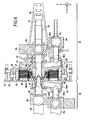
- FIG. 9 is a section view on an axial vertical plane of the fueling device seen from direction IX of FIG. 4 , at the front of a locking finger.
- FIGS. 1 to 3 are diagrams showing the principle of the invention with a fueling device 10 comprising a ground module 20 , to the right in the figures, and an on-board module 30 , to the left in the figures.
- the ground and on-board modules 20 and 30 are in position connected to each other and the fueling circuit is open to allow the tanks to be fed with fluid.
- the ground module 20 From upstream to downstream in the direction of arrows that show the flow of the fuel fluid, the ground module 20 comprises a ground valve 21 housed in or opening out into a ground pipe 22 placed upstream from a source of fuel fluid (not shown), a ground control unit 24 , and a ground plate 26 including a ground passage 28 leading to the on-board module 30 .
- the ground control unit 24 is shown in the form of an actuator having a piston 24 a that is slidably movable in a cylinder 24 b that defines two chambers: a front chamber 24 c connected to the ground pipe 22 and a rear chamber 24 d in which the piston head 24 e is housed.
- An opening 24 f in the rear chamber 24 d enables gas under pressure to enter therein, thereby enabling the piston head 24 e to advance into an advanced position, driving the piston rod 24 g to the left in FIG. 1 , into the on-board module 30 , thereby placing an on-board valve 36 in an open position, the valve member 36 a of the on-board valve 36 being beforehand in a closed position.
- the rear chamber 24 d also includes return means (here a coil spring 24 h ) serving to return the piston 24 a into a rear position which corresponds to a closed position for the on-board valve 36 ( FIGS. 2 and 3 ) when the pressure of gas in the rear chamber 24 d decreases.
- return means here a coil spring 24 h
- the on-board plate 26 surrounds the front portion of the cylinder 24 b of the piston 24 a defining the ground passage 28 extending the front chamber 24 c.
- the on-board module 30 comprises an on-board plate 32 defining a passage 34 that, in FIGS. 1 and 2 , extends the ground passage 28 , and comprises also the on-board valve 36 and an on-board pipe 38 connected to the cryogenic tanks.
- the on-board valve 36 is shown in the form of a valve member 36 a or plug suitable for closing the on-board passage 34 , having a portion that forms the seat 36 b of the on-board valve 36 , and an O-ring 36 c serving to improve sealing between the valve member 36 a and the seat 36 b when the on-board valve 36 is in the closed position ( FIG. 3 ).
- Return means serve to return the on-board valve 36 to the closed position in which the on-board passage 34 is no longer in fluid communication with the ground passage 28 ( FIG. 3 ).
- opening/closing control of the ground valve 21 is independent of opening/closing control of the on-board valve 36 .
- FIGS. 1A to 1C there can be seen a variant embodiment that differs from the embodiment of FIGS. 1 to 3 by the fact that the ground valve 21 is housed in the front chamber 24 c and is also controlled by the ground control unit 24 .
- the ground valve 21 comprises an annular valve member 21 a securely mounted around the piston rod 24 g and an annular seat 21 b mounted on the inside face of the wall of the cylinder 24 b , behind the valve member 21 a .
- An O-ring 21 c serves to improve sealing between the valve member 21 a and the seat 21 b when the ground valve 21 is in the closed position ( FIGS. 2A and 3A ).
- Forward movement of the piston rod 24 g (to the left in FIGS. 1A to 3A ) serves, by moving both the valve member 36 a of the on-board valve 36 and the valve member 21 a of the ground valve 21 in a forward direction, to open simultaneously the on-board valve 36 and the ground valve 21 .
- causing the ground valve 21 to open also causes the on-board valve 36 to open, and causing the ground valve 21 to close also causes the on-board valve 36 to close.
- FIGS. 1 and 1A show the situation in which the opening 24 f leads into the rear portion of the rear chamber 24 d , while the coil spring 24 h bears against the piston head 24 e by being housing in the front portion of the rear chamber 24 d , however this arrangement could be inverted (opening 24 f leading into the front portion of the rear chamber 24 d and coil spring 24 h housed in the rear portion of the rear chamber 24 d ). It is also possible to use two openings leading respectively into the front portion and into the rear portion of the rear chamber 24 d , which openings are suitable for delivering gas at different pressures, thereby enabling the piston head 24 e and the piston rod 24 g to be caused to move forwards or rearwards.
- the ground control unit 24 is constituted by no more than the cylinder 24 b defining a single chamber without a piston that is connected to the ground pipe 22 .
- it is the pressure of the fluid penetrating via the ground pipe that serves to move the valve member 36 a and to open the on-board valve 36 .
- the ground valve (not shown) is situated upstream from the hydraulic coupling system 40 .
- provision may also be made (configuration not shown) for the on-board valve 36 to be placed further downstream in the hydraulic coupling system 40 : thus, each of the ground valve 21 and the on-board valve 36 has its own control unit.
- the ground module 20 and the on-board module 30 are connected to each other via a hydraulic coupling system 40 that comprises an annular gasket 40 a providing sealing between the ground module 20 and the on-board module 30 (between the on-board plate 32 and the ground plate 26 ).
- a first annular enclosure 50 surrounds the hydraulic coupling system 40 , which enclosure is suitable for being connected to suction.
- this first annular enclosure 50 extends between the ground plate 26 and the on-board plate 32 (respectively to the right and to the left in FIGS. 1 to 3 ).
- the first annular enclosure 50 is defined in an outward radial direction by a first annular bellows 52 surrounding the hydraulic coupling system 40 and having its end bearing in leaktight manner against the on-board plate 32 and the ground plate 26 .
- the ground plate includes an opening 54 leading into said first enclosure 50 and suitable for being connected to suction means (not shown).
- the ground plate 26 and the on-board plate 32 are held in connection by a suction-cup effect, thereby enabling the ground module 20 and the on-board module 30 to be kept connected together (see FIGS. 1 and 2 , 1 A and 1 B, and 1 C).
- the gas pressure is increased in the first annular enclosure 50 by injecting gas via the opening 54 so that the ground and on-board modules 20 and 30 are disconnected and become mutually separable, e.g. during launcher climb.
- This increase in the gas pressures inside the first annular enclosure 50 may involve applying atmospheric pressure or a higher pressure (a pressure higher than atmospheric pressure).
- the invention makes it very simple, merely by having a negative pressure difference between the first annular enclosure 50 and the outside, to keep the ground module 20 and the on-board module 30 connected together, this connection being opened by varying the pressure inside the first annular enclosure 50 (connecting it to atmospheric pressure or to a higher pressure).
- FIGS. 4 to 9 show more particularly an embodiment of the fueling device 10 .
- reference signs that are already used above are used again to designate portions of the fueling device that are already mentioned above.
- This embodiment has two parallel flow paths for feeding and discharging fluid, e.g. making it possible to fill simultaneously the cryogenic tanks with different propellants (different in chemical nature and/or physical state), and in particular with a liquid propellant and a gaseous propellant, e.g. liquid oxygen via one part and gaseous oxygen in parallel via the other.
- different propellants different in chemical nature and/or physical state
- a liquid propellant and a gaseous propellant e.g. liquid oxygen via one part and gaseous oxygen in parallel via the other.
- the two parallel flow paths for feeding fluid are coaxial.
- the first ground passage 28 1 and the second ground passage 28 2 are mutually coaxial, as are the first on-board passage 34 1 and the second on-board passage 34 2 , at least over a segment of said passages 28 1 , 28 2 , 34 1 , 34 2 .
- the first ground assembly formed by the first ground pipe 22 1 and the first ground valve 24 1 is situated parallel beside the second ground assembly formed by the second ground pipe 22 2 and the second ground valve 24 2 .
- This first ground assembly is mounted on the ground plate 26 at a first location forming the opening of the first ground passage 28 1 that is rectilinear all the way to its outlet.
- This second ground assembly is mounted on the ground plate 26 at a second location forming the opening of the second ground passage 28 2 that presents, successively in line with one another, a first rectilinear portion 28 2 a that is parallel to the axis X and to the second ground pipe 22 2 , a second rectilinear portion 28 2 b that is substantially parallel to the axis Y that extends at almost right angles from the first portion 28 2 a towards the first ground passage 28 1 , and an annular third portion 28 2 c that extends as far as the outlet of the second ground passage 28 2 and that surrounds the downstream portion of the first ground passage 28 1 (see FIG. 7 ).
- the first on-board assembly formed by the first on-board pipe 38 1 and the first on-board valve 36 1 is situated parallel beside the second on-board assembly formed by the second on-board pipe 38 2 and the second on-board valve 36 2 .
- This first on-board assembly is mounted on the on-board plate 32 at a first location forming the opening of the first on-board passage 34 1 and it is rectilinear all the way to its outlet.
- This second on-board assembly is mounted on the on-board plate 32 at a second location forming the opening of the second on-board passage 34 2 and that presents, successively in line with one another, a rectilinear first portion 34 2 a parallel to the axis X and to the second on-board pipe 38 2 , a rectilinear second portion 34 2 b substantially parallel to the axis Y and extending at almost right angles relative to the first portion 34 2 a towards the first on-board passage 34 1 , and an annular third portion 34 2 c that extends as far as the outlet of the second on-board passage 34 2 and that surrounds the downstream portion of the first on-board passage 34 1 (see FIG. 7 ).
- a filter 35 is located inside the first on-board passage 34 1 that is intended more particularly for passing a liquid, in order to avoid particles polluting the fluid flow passage downstream from the fueling device 10 .
- valves are ball valves.
- valves of other types such as flap valves.
- the hydraulic coupling system 40 is described below with reference to FIGS. 5 and 6 : around the inlet of the first on-board passage 34 1 in the on-board plate 32 , a threaded annular collar 33 receives a centralizing annular cover 37 by screw-fastening, with the free end 37 a thereof that points away from the on-board plate 32 being crenellated and flared.
- This free end 37 a serves to receive a projecting annular portion 27 formed on the face of the ground plate 26 that faces towards the on-board module 30 by surrounding said projecting annular portion 27 , which itself surrounds the downstream portion of the first ground passage 28 1 .
- the hydraulic coupling system 40 thus essentially comprises the annular collar 33 of the on-board plate 32 , the centralizing annular cover 37 , and the projecting annular portion 27 of the ground plate 26 .
- the outer annular faces of the annular collar 33 and of the centralizing annular cover 37 are provided with respective O-rings.
- a first annular enclosure 50 defined radially on the outside by the first annular bellows 52 surrounds the hydraulic coupling system 40 .
- the opening 54 of the first ground plate is axially in line (along the X axis) with the first annular enclosure 50 and by being connected to suction means (e.g. a pump) it serves to apply suction to the first annular enclosure 50 .
- suction means e.g. a pump
- the end walls of the first annular bellows 52 that are covered in an O-ring are “stuck” against the facing faces of the ground and on-board plates 26 and 32 , thereby creating a suction-cup type connection.
- the fueling device 10 of FIGS. 5 to 9 further includes a second annular enclosure 60 suitable for being connected to high pressure, the second enclosure being situated between the on-board plate 32 and the ground plate 26 around the hydraulic coupling system 40 and around which the first annular enclosure 50 is located.
- This second annular enclosure 60 is defined radially on the outside by a second annular bellows 62 (see FIGS. 4 to 6 ) that surrounds the hydraulic coupling system 40 and that is itself surrounded by the first annular bellows 52 .
- the second annular enclosure 60 is pressurized by means of a dedicated feed (duct 63 in FIG. 6 ) that enables an inert gas under pressure to be introduced via an opening in the ground plate 26 : this avoids any dangerous substances penetrating into the suction zone.
- Maintaining the second annular enclosure 60 under pressure does not compromise maintaining the ground module 20 and the on-board module 30 in a connected position since the first annular enclosure 50 is outside the second annular enclosure 60 and is of a size that is sufficient to ensure that the suction inside the first annular enclosure maintains coupling between the on-board module 30 and the ground module 20 .
- the extra pressure in the second annular enclosure 60 makes it possible, where necessary, to condition the hydraulic coupling system 40 , i.e. to add an anti-frosting system thereto in the form of a flow of gas (dry air or nitrogen) outside the first bellows 52 (duct 64 in FIG. 6 ), thereby making it possible to avoid ice forming, in particular in the zone of contact between the first bellows 52 and the on-board plate 32 .
- the fueling device 10 of FIGS. 5 to 9 also includes, between the on-board plate 32 and the ground plate 26 , a mechanical locking system 70 that suitable for opening while the launcher is climbing when lifting off, or beforehand.
- the mechanical locking system 70 includes, on either side of the first annular enclosure 50 , a release fork 72 having a bottom end 72 a bearing against the on-board plate 32 in the connected position via a receiver portion 39 against which the bottom end 72 a bears via a complementary shape, while the top end 72 b of the release fork 72 is pivotally mounted about a ground pin 29 secured to the ground plate 26 so that pivoting of the release fork 72 about the ground pin 29 moves the ground plate 26 apart from the on-board plate 32 or gives rise to a cracking point on the structure on which the ground plate 32 is fastened (until the moment when the bottom end 72 a escapes from the receiver portion 39 ), and vice versa.
- the release fork 72 is provided between its bottom end 72 a and its top end 72 b with a hole enabling a sling to be attached thereto, the other end of the sling being fastened to the ground. In this manner, while the launcher is climbing, the ground module 20 is thus retained and separated from the on-board module which is secured to the launcher.
- the mechanical locking system 70 includes, on either side of the first annular enclosure 50 , a locking finger 74 (see FIG. 9 ) that is movable in pivoting about the ground pin 29 between an open position (not shown) that does not hold the ground plate 26 and the on-board plate 32 together, and a closed position ( FIGS. 4 and 6 ) in which the ground plate 26 and the on-board plate 32 are held together by the fact that the housing 74 b defined by the top end 74 a of the locking finger 74 receives an on-board pin 31 secured to the on-board plate 32 .
- the mechanical locking system 70 also includes a connection shaft 76 connecting together the bottom ends 74 c of the locking fingers 74 and having mounted thereon (via a hinge) the free end of the piston rod 78 a of a control actuator 78 serving to actuate opening or closing of the locking fingers 74 .
- the cylinder 78 b of the control actuator 78 is mounted at the rear of the ground plate 26 by means of a V-shaped actuator support 80 projecting at right angles from the rear of the ground plate 26 .
- the actuator 78 serves to release the on-board pins 31 from the locking fingers 74 and thus enables the ground module 20 to be separated from the on-board module 30 while the launcher is climbing.
Landscapes
- Engineering & Computer Science (AREA)
- Physics & Mathematics (AREA)
- Astronomy & Astrophysics (AREA)
- General Physics & Mathematics (AREA)
- Remote Sensing (AREA)
- Aviation & Aerospace Engineering (AREA)
- Filling Or Discharging Of Gas Storage Vessels (AREA)
- Actuator (AREA)
- Loading And Unloading Of Fuel Tanks Or Ships (AREA)
- Portable Nailing Machines And Staplers (AREA)
- Fluid-Pressure Circuits (AREA)
- Vehicle Cleaning, Maintenance, Repair, Refitting, And Outriggers (AREA)
Applications Claiming Priority (3)
| Application Number | Priority Date | Filing Date | Title |
|---|---|---|---|
| FR0951958 | 2009-03-30 | ||
| FR0951958A FR2943626B1 (fr) | 2009-03-30 | 2009-03-30 | Dispositif d'avitaillement de propulseurs d'un lanceur |
| PCT/FR2010/050557 WO2010112736A1 (fr) | 2009-03-30 | 2010-03-26 | Dispositif d'avitaillement de propulseurs d'un lanceur |
Publications (2)
| Publication Number | Publication Date |
|---|---|
| US20120024421A1 US20120024421A1 (en) | 2012-02-02 |
| US8991444B2 true US8991444B2 (en) | 2015-03-31 |
Family
ID=41278712
Family Applications (1)
| Application Number | Title | Priority Date | Filing Date |
|---|---|---|---|
| US13/262,113 Active 2032-05-06 US8991444B2 (en) | 2009-03-30 | 2010-03-26 | Device for fueling launcher thrusters |
Country Status (7)
| Country | Link |
|---|---|
| US (1) | US8991444B2 (https=) |
| EP (1) | EP2414242B1 (https=) |
| JP (1) | JP5706872B2 (https=) |
| CN (1) | CN102387964A (https=) |
| FR (1) | FR2943626B1 (https=) |
| RU (1) | RU2527584C2 (https=) |
| WO (1) | WO2010112736A1 (https=) |
Cited By (4)
| Publication number | Priority date | Publication date | Assignee | Title |
|---|---|---|---|---|
| US20170341769A1 (en) * | 2016-05-29 | 2017-11-30 | Neoex Systems, Inc. | System and method for the transfer of cryogenic fluids |
| US10308376B2 (en) * | 2014-01-29 | 2019-06-04 | Safran Aircraft Engines | Propellant feed system for a space vehicle |
| US12011989B1 (en) | 2021-01-17 | 2024-06-18 | Neoex Systems, Inc. | Direct liquefaction for vehicle refueling |
| US12429153B2 (en) * | 2021-05-28 | 2025-09-30 | Engineered Controls International, Llc | Low-emission nozzle and receptacle coupling for cryogenic fluid |
Families Citing this family (13)
| Publication number | Priority date | Publication date | Assignee | Title |
|---|---|---|---|---|
| US10125052B2 (en) | 2008-05-06 | 2018-11-13 | Massachusetts Institute Of Technology | Method of fabricating electrically conductive aerogels |
| US8785881B2 (en) | 2008-05-06 | 2014-07-22 | Massachusetts Institute Of Technology | Method and apparatus for a porous electrospray emitter |
| FR2943626B1 (fr) * | 2009-03-30 | 2011-04-22 | Snecma | Dispositif d'avitaillement de propulseurs d'un lanceur |
| US10308377B2 (en) | 2011-05-03 | 2019-06-04 | Massachusetts Institute Of Technology | Propellant tank and loading for electrospray thruster |
| US20140303129A1 (en) * | 2013-03-15 | 2014-10-09 | Clarus Therapeutics, Inc. | Methods of treating testosterone deficiency |
| WO2016164004A1 (en) * | 2015-04-08 | 2016-10-13 | Massachusetts Institute Of Technology | Propellant tank and loading for electrospray thruster |
| BE1023109B1 (fr) * | 2015-05-18 | 2016-11-23 | Techspace Aero S.A. | Module de raccordement d'avitaillement pour lanceur spatial |
| CN106005487B (zh) * | 2015-07-03 | 2018-02-13 | 中国运载火箭技术研究院 | 一种空间在轨加注对接接口装置 |
| EP3482059B1 (en) * | 2016-07-11 | 2020-11-11 | Aerojet Rocketdyne, Inc. | Ground hydraulic system hypergolic slug injection |
| US10141855B2 (en) | 2017-04-12 | 2018-11-27 | Accion Systems, Inc. | System and method for power conversion |
| EP3973182A4 (en) | 2019-05-21 | 2023-06-28 | Accion Systems, Inc. | Apparatus for electrospray emission |
| US12104583B2 (en) | 2020-08-24 | 2024-10-01 | Accion Systems, Inc. | Propellant apparatus |
| CN114784579B (zh) * | 2022-05-18 | 2023-05-09 | 重庆交通职业学院 | 一种安全性高的新能源汽车充电枪及使用方法 |
Citations (39)
| Publication number | Priority date | Publication date | Assignee | Title |
|---|---|---|---|---|
| US2533640A (en) * | 1947-10-25 | 1950-12-12 | Raymond M Ulrich | Quick disconnect hydraulic coupler |
| US3045721A (en) * | 1960-02-04 | 1962-07-24 | Dover Corp | Under-wing fueling nozzle |
| US3112672A (en) * | 1962-03-07 | 1963-12-03 | James E Webb | Umbilical separator for rockets |
| US3164165A (en) * | 1962-05-11 | 1965-01-05 | Thiokol Chemical Corp | Relief valve for use with cryogenic fluids |
| US3216466A (en) * | 1961-09-20 | 1965-11-09 | Litton Systems Inc | Pressure actuated release mechanism |
| US3217762A (en) * | 1963-07-19 | 1965-11-16 | Kreisler Mfg Corp Jacques | Refill valve for gas lighter |
| US3249013A (en) * | 1964-04-03 | 1966-05-03 | Jr Joseph D Pride | Remote controlled tubular disconnect |
| US3261483A (en) * | 1963-05-24 | 1966-07-19 | Peter T Calabretta | Adapter valve |
| US3501059A (en) * | 1967-05-05 | 1970-03-17 | Ary Van Der Lely | Implements for transporting materials |
| US3530906A (en) * | 1967-06-01 | 1970-09-29 | Standard Oil Co | Apparatus for automatically fuelling vehicles |
| US3763747A (en) * | 1971-06-28 | 1973-10-09 | Aerojet General Co | Fluid-operable linear actuators |
| US3863688A (en) * | 1973-06-18 | 1975-02-04 | Parker Hannifin Corp | Convertor for top loading tanks |
| EP0146684A1 (de) | 1983-12-21 | 1985-07-03 | Uhde GmbH | Rohrverbindung mit fernbetätigbaren Festlege- und Löse-einrichtungen |
| US4567924A (en) * | 1983-02-25 | 1986-02-04 | Brown Albert W | Aircraft under-wing fueling nozzle system |
| US5117876A (en) * | 1991-04-11 | 1992-06-02 | Spokane Industries, Inc. | Defueling fitting and method for removing fuel from an aircraft fuel cell |
| US5301723A (en) * | 1992-11-06 | 1994-04-12 | Hydra Rig, Inc. | Apparatus and method of preventing ice accumulation on coupling valves for cryogenic fluids |
| US5404923A (en) * | 1993-05-26 | 1995-04-11 | Rockwell International Corporation | Apparatus for automated fueling of a launch vehicle |
| US5404909A (en) * | 1992-06-11 | 1995-04-11 | Parker-Hannifin Corporation | Coupling device |
| US5765612A (en) * | 1996-08-21 | 1998-06-16 | Morin; Claude | Quick-connect engine oil drainage system |
| US5904302A (en) * | 1997-03-21 | 1999-05-18 | Brown; Albert W. | Aircraft fueling nozzle |
| US6125871A (en) * | 1999-01-22 | 2000-10-03 | Ashland, Inc. | Valve assembly with flush and sample capability |
| US6142194A (en) * | 1999-03-09 | 2000-11-07 | Cla-Val | Pressure fuel servicing nozzle |
| US20010054818A1 (en) * | 2000-06-23 | 2001-12-27 | Hiroshi Fujikawa | Device for coupling pipelines for running cryogenic liquid |
| US20020014279A1 (en) * | 2000-05-03 | 2002-02-07 | Hall Industries , Inc. | Preconditioned air adapter chute |
| US20040055642A1 (en) * | 2002-07-12 | 2004-03-25 | Dominique Valentian | Cryogenic rotary coupling, and use thereof in particular in articulated fluid feed lines, and in cryogenic propellant rocket engines |
| US20040129906A1 (en) * | 2002-12-18 | 2004-07-08 | Snecma Moteurs | Cryogenic valve device |
| US20040148925A1 (en) * | 2002-08-09 | 2004-08-05 | Knight Andrew F. | Pressurizer for a rocket engine |
| US20050151107A1 (en) * | 2003-12-29 | 2005-07-14 | Jianchao Shu | Fluid control system and stem joint |
| US20050247352A1 (en) * | 2004-04-26 | 2005-11-10 | Takanobu Kamiya | Connector, fluid supply apparatus, movable body, fluid supply system, and connector connection method and connector separation method |
| US7194853B1 (en) * | 2001-06-12 | 2007-03-27 | Knight Andrew F | Pressurizer for a rocket engine |
| US7257940B1 (en) * | 2001-06-12 | 2007-08-21 | Knight Andrew F | Device and method for pumping a fluid |
| US20080216640A1 (en) * | 2005-01-27 | 2008-09-11 | John Brand | Lightweight rammer |
| US20080315038A1 (en) * | 2005-12-22 | 2008-12-25 | Airbus Uk Limited | Fuel Tank Valve |
| US20100018608A1 (en) * | 2008-07-24 | 2010-01-28 | Daniel Joseph Huegerich | Arm Arrangement For Supporting Coupler Section Carried At End Of Nurse Vehicle Fluid Transfer Conduit |
| US7681482B1 (en) * | 2008-09-03 | 2010-03-23 | The Boeing Company | Automatic connector system |
| FR2943626A1 (fr) * | 2009-03-30 | 2010-10-01 | Snecma | Dispositif d'avitaillement de propulseurs d'un lanceur |
| US20110127395A1 (en) * | 2008-03-25 | 2011-06-02 | Bohle Ag | Vacuum lifter |
| US20120080563A1 (en) * | 2007-03-09 | 2012-04-05 | Macdonald Dettwiler & Associates Inc. | Robotic satellite refueling tool |
| US8820353B2 (en) * | 2010-06-30 | 2014-09-02 | Carleton Technologies, Inc. | Interface assembly for space vehicles |
Family Cites Families (6)
| Publication number | Priority date | Publication date | Assignee | Title |
|---|---|---|---|---|
| JPS60245895A (ja) * | 1984-05-17 | 1985-12-05 | 川崎重工業株式会社 | 二重偶管構造 |
| JPH01182199A (ja) * | 1988-01-14 | 1989-07-20 | Natl Space Dev Agency Japan<Nasda> | ロツクリリースピン |
| US5582366A (en) * | 1995-01-19 | 1996-12-10 | Motorola, Inc. | Satellite fueling system and method therefor |
| JP4616436B2 (ja) * | 1999-12-14 | 2011-01-19 | 三菱重工業株式会社 | 流体注入装置 |
| RU2179941C1 (ru) * | 2001-07-12 | 2002-02-27 | ЗАО "Пусковые услуги" | Космический ракетный комплекс и способ обеспечения услуг по запуску космических аппаратов с использованием космического ракетного комплекса |
| JP3711369B2 (ja) * | 2001-10-02 | 2005-11-02 | 独立行政法人 宇宙航空研究開発機構 | 極低温配管継手 |
-
2009
- 2009-03-30 FR FR0951958A patent/FR2943626B1/fr not_active Expired - Fee Related
-
2010
- 2010-03-26 US US13/262,113 patent/US8991444B2/en active Active
- 2010-03-26 WO PCT/FR2010/050557 patent/WO2010112736A1/fr not_active Ceased
- 2010-03-26 JP JP2012502739A patent/JP5706872B2/ja active Active
- 2010-03-26 EP EP10715987.3A patent/EP2414242B1/fr active Active
- 2010-03-26 RU RU2011140789/11A patent/RU2527584C2/ru active
- 2010-03-26 CN CN2010800153755A patent/CN102387964A/zh active Pending
Patent Citations (42)
| Publication number | Priority date | Publication date | Assignee | Title |
|---|---|---|---|---|
| US2533640A (en) * | 1947-10-25 | 1950-12-12 | Raymond M Ulrich | Quick disconnect hydraulic coupler |
| US3045721A (en) * | 1960-02-04 | 1962-07-24 | Dover Corp | Under-wing fueling nozzle |
| US3216466A (en) * | 1961-09-20 | 1965-11-09 | Litton Systems Inc | Pressure actuated release mechanism |
| US3112672A (en) * | 1962-03-07 | 1963-12-03 | James E Webb | Umbilical separator for rockets |
| US3164165A (en) * | 1962-05-11 | 1965-01-05 | Thiokol Chemical Corp | Relief valve for use with cryogenic fluids |
| US3261483A (en) * | 1963-05-24 | 1966-07-19 | Peter T Calabretta | Adapter valve |
| US3217762A (en) * | 1963-07-19 | 1965-11-16 | Kreisler Mfg Corp Jacques | Refill valve for gas lighter |
| US3249013A (en) * | 1964-04-03 | 1966-05-03 | Jr Joseph D Pride | Remote controlled tubular disconnect |
| US3501059A (en) * | 1967-05-05 | 1970-03-17 | Ary Van Der Lely | Implements for transporting materials |
| US3530906A (en) * | 1967-06-01 | 1970-09-29 | Standard Oil Co | Apparatus for automatically fuelling vehicles |
| US3763747A (en) * | 1971-06-28 | 1973-10-09 | Aerojet General Co | Fluid-operable linear actuators |
| US3863688A (en) * | 1973-06-18 | 1975-02-04 | Parker Hannifin Corp | Convertor for top loading tanks |
| US4567924A (en) * | 1983-02-25 | 1986-02-04 | Brown Albert W | Aircraft under-wing fueling nozzle system |
| EP0146684A1 (de) | 1983-12-21 | 1985-07-03 | Uhde GmbH | Rohrverbindung mit fernbetätigbaren Festlege- und Löse-einrichtungen |
| US5117876A (en) * | 1991-04-11 | 1992-06-02 | Spokane Industries, Inc. | Defueling fitting and method for removing fuel from an aircraft fuel cell |
| US5404909A (en) * | 1992-06-11 | 1995-04-11 | Parker-Hannifin Corporation | Coupling device |
| US5301723A (en) * | 1992-11-06 | 1994-04-12 | Hydra Rig, Inc. | Apparatus and method of preventing ice accumulation on coupling valves for cryogenic fluids |
| US5404923A (en) * | 1993-05-26 | 1995-04-11 | Rockwell International Corporation | Apparatus for automated fueling of a launch vehicle |
| US5765612A (en) * | 1996-08-21 | 1998-06-16 | Morin; Claude | Quick-connect engine oil drainage system |
| US5904302A (en) * | 1997-03-21 | 1999-05-18 | Brown; Albert W. | Aircraft fueling nozzle |
| US6125871A (en) * | 1999-01-22 | 2000-10-03 | Ashland, Inc. | Valve assembly with flush and sample capability |
| US6405768B1 (en) * | 1999-03-09 | 2002-06-18 | Cla-Val Co. | Pressure fuel servicing nozzle |
| US6142194A (en) * | 1999-03-09 | 2000-11-07 | Cla-Val | Pressure fuel servicing nozzle |
| US20020014279A1 (en) * | 2000-05-03 | 2002-02-07 | Hall Industries , Inc. | Preconditioned air adapter chute |
| US20010054818A1 (en) * | 2000-06-23 | 2001-12-27 | Hiroshi Fujikawa | Device for coupling pipelines for running cryogenic liquid |
| US7257940B1 (en) * | 2001-06-12 | 2007-08-21 | Knight Andrew F | Device and method for pumping a fluid |
| US7194853B1 (en) * | 2001-06-12 | 2007-03-27 | Knight Andrew F | Pressurizer for a rocket engine |
| US20040055642A1 (en) * | 2002-07-12 | 2004-03-25 | Dominique Valentian | Cryogenic rotary coupling, and use thereof in particular in articulated fluid feed lines, and in cryogenic propellant rocket engines |
| US7082750B2 (en) * | 2002-08-09 | 2006-08-01 | Knight Andrew F | Pressurizer for a rocket engine |
| US20040148925A1 (en) * | 2002-08-09 | 2004-08-05 | Knight Andrew F. | Pressurizer for a rocket engine |
| US20040129906A1 (en) * | 2002-12-18 | 2004-07-08 | Snecma Moteurs | Cryogenic valve device |
| US20050151107A1 (en) * | 2003-12-29 | 2005-07-14 | Jianchao Shu | Fluid control system and stem joint |
| US20050247352A1 (en) * | 2004-04-26 | 2005-11-10 | Takanobu Kamiya | Connector, fluid supply apparatus, movable body, fluid supply system, and connector connection method and connector separation method |
| US20080216640A1 (en) * | 2005-01-27 | 2008-09-11 | John Brand | Lightweight rammer |
| US20080315038A1 (en) * | 2005-12-22 | 2008-12-25 | Airbus Uk Limited | Fuel Tank Valve |
| US20120080563A1 (en) * | 2007-03-09 | 2012-04-05 | Macdonald Dettwiler & Associates Inc. | Robotic satellite refueling tool |
| US20110127395A1 (en) * | 2008-03-25 | 2011-06-02 | Bohle Ag | Vacuum lifter |
| US20100018608A1 (en) * | 2008-07-24 | 2010-01-28 | Daniel Joseph Huegerich | Arm Arrangement For Supporting Coupler Section Carried At End Of Nurse Vehicle Fluid Transfer Conduit |
| US7681482B1 (en) * | 2008-09-03 | 2010-03-23 | The Boeing Company | Automatic connector system |
| FR2943626A1 (fr) * | 2009-03-30 | 2010-10-01 | Snecma | Dispositif d'avitaillement de propulseurs d'un lanceur |
| US20120024421A1 (en) * | 2009-03-30 | 2012-02-02 | Eric Boutet | Device for fueling launcher thrusters |
| US8820353B2 (en) * | 2010-06-30 | 2014-09-02 | Carleton Technologies, Inc. | Interface assembly for space vehicles |
Cited By (8)
| Publication number | Priority date | Publication date | Assignee | Title |
|---|---|---|---|---|
| US10308376B2 (en) * | 2014-01-29 | 2019-06-04 | Safran Aircraft Engines | Propellant feed system for a space vehicle |
| US20170341769A1 (en) * | 2016-05-29 | 2017-11-30 | Neoex Systems, Inc. | System and method for the transfer of cryogenic fluids |
| US10773822B2 (en) * | 2016-05-29 | 2020-09-15 | Neoex Systems, Inc. | System and method for the transfer of cryogenic fluids |
| US10981666B1 (en) * | 2016-05-29 | 2021-04-20 | Neoex Systems, Inc. | System and method for the transfer of cryogenic fluids |
| US11286055B2 (en) | 2016-05-29 | 2022-03-29 | Neoex Systems, Inc. | System and method for the transfer of cryogenic fluids |
| US12011989B1 (en) | 2021-01-17 | 2024-06-18 | Neoex Systems, Inc. | Direct liquefaction for vehicle refueling |
| US12429153B2 (en) * | 2021-05-28 | 2025-09-30 | Engineered Controls International, Llc | Low-emission nozzle and receptacle coupling for cryogenic fluid |
| US12601435B2 (en) | 2021-05-28 | 2026-04-14 | Engineered Controls International, Llc | Low-emission nozzle and receptacle coupling for cryogenic fluid |
Also Published As
| Publication number | Publication date |
|---|---|
| EP2414242B1 (fr) | 2013-05-08 |
| FR2943626B1 (fr) | 2011-04-22 |
| JP5706872B2 (ja) | 2015-04-22 |
| JP2012521927A (ja) | 2012-09-20 |
| US20120024421A1 (en) | 2012-02-02 |
| RU2011140789A (ru) | 2013-05-10 |
| EP2414242A1 (fr) | 2012-02-08 |
| RU2527584C2 (ru) | 2014-09-10 |
| FR2943626A1 (fr) | 2010-10-01 |
| CN102387964A (zh) | 2012-03-21 |
| WO2010112736A1 (fr) | 2010-10-07 |
Similar Documents
| Publication | Publication Date | Title |
|---|---|---|
| US8991444B2 (en) | Device for fueling launcher thrusters | |
| EP2148119B1 (en) | A fluid coupler arrangement, combination of a fluid coupler arrangement with a control arrangement and combination of a variable displacement pump with a control system | |
| CN109163624B (zh) | 一种可分离的火箭推进系统 | |
| EP3689758B1 (en) | A fluid transfer system | |
| CN102159494B (zh) | 燃料分配喷嘴 | |
| CN114291297B (zh) | 月面发射飞行器推进系统 | |
| EP3696080B1 (en) | Tethered helium kite gas replenishment device and gas replenishment method | |
| CN102213352A (zh) | 具有夹紧模块的流体传输管路 | |
| US9162775B2 (en) | Venting gas from a tank | |
| US20170260929A1 (en) | Device and locking of a fueling device | |
| US12072063B2 (en) | Safety joint | |
| EP3925893A1 (fr) | Procédé de dépressurisation d'une cabine d'un aéronef au sol depuis l extérieur de l aéronef | |
| US6848481B1 (en) | Method and apparatus for removing hazardous liquid from petroleum tanker trailer delivery/loading piping | |
| US6289818B1 (en) | Stage separation system and method | |
| US10308376B2 (en) | Propellant feed system for a space vehicle | |
| US10640213B2 (en) | Ejector rack | |
| EP4455021A1 (fr) | Aéronef comprenant au moins un dispositif d'alimentation en hydrogène équipé d'au moins un système d'évacuation de gaz en cas de fuite | |
| CN114941800B (zh) | 一种火箭可燃推进剂加注平台及加注方法 | |
| US9676495B2 (en) | Hydrant coupler with articulating handle assembly | |
| CN107002931A (zh) | 具有紧急释放系统的用于递送加压气体的耦合组合件 | |
| Schneider | Method and Apparatus for Coupling Space Vehicles |
Legal Events
| Date | Code | Title | Description |
|---|---|---|---|
| AS | Assignment |
Owner name: SNECMA, FRANCE Free format text: ASSIGNMENT OF ASSIGNORS INTEREST;ASSIGNORS:BOUTET, ERIC;PATTYN, JEAN-LUC;MEYER, FRANCIS;REEL/FRAME:027133/0071 Effective date: 20110902 |
|
| STCF | Information on status: patent grant |
Free format text: PATENTED CASE |
|
| AS | Assignment |
Owner name: SAFRAN AIRCRAFT ENGINES, FRANCE Free format text: CHANGE OF NAME;ASSIGNOR:SNECMA;REEL/FRAME:046479/0807 Effective date: 20160803 |
|
| MAFP | Maintenance fee payment |
Free format text: PAYMENT OF MAINTENANCE FEE, 4TH YEAR, LARGE ENTITY (ORIGINAL EVENT CODE: M1551); ENTITY STATUS OF PATENT OWNER: LARGE ENTITY Year of fee payment: 4 |
|
| AS | Assignment |
Owner name: SAFRAN AIRCRAFT ENGINES, FRANCE Free format text: CORRECTIVE ASSIGNMENT TO CORRECT THE COVER SHEET TO REMOVE APPLICATION NOS. 10250419, 10786507, 10786409, 12416418, 12531115, 12996294, 12094637 12416422 PREVIOUSLY RECORDED ON REEL 046479 FRAME 0807. ASSIGNOR(S) HEREBY CONFIRMS THE CHANGE OF NAME;ASSIGNOR:SNECMA;REEL/FRAME:046939/0336 Effective date: 20160803 |
|
| MAFP | Maintenance fee payment |
Free format text: PAYMENT OF MAINTENANCE FEE, 8TH YEAR, LARGE ENTITY (ORIGINAL EVENT CODE: M1552); ENTITY STATUS OF PATENT OWNER: LARGE ENTITY Year of fee payment: 8 |