EP2412636B3 - Anlage zur Verpackung von Warenlosen - Google Patents
Anlage zur Verpackung von Warenlosen Download PDFInfo
- Publication number
- EP2412636B3 EP2412636B3 EP11173722.7A EP11173722A EP2412636B3 EP 2412636 B3 EP2412636 B3 EP 2412636B3 EP 11173722 A EP11173722 A EP 11173722A EP 2412636 B3 EP2412636 B3 EP 2412636B3
- Authority
- EP
- European Patent Office
- Prior art keywords
- conveyor
- transfer conveyor
- products
- batches
- conveyor belt
- Prior art date
- Legal status (The legal status is an assumption and is not a legal conclusion. Google has not performed a legal analysis and makes no representation as to the accuracy of the status listed.)
- Active
Links
Images



Classifications
-
- B—PERFORMING OPERATIONS; TRANSPORTING
- B65—CONVEYING; PACKING; STORING; HANDLING THIN OR FILAMENTARY MATERIAL
- B65B—MACHINES, APPARATUS OR DEVICES FOR, OR METHODS OF, PACKAGING ARTICLES OR MATERIALS; UNPACKING
- B65B65/00—Details peculiar to packaging machines and not otherwise provided for; Arrangements of such details
- B65B65/003—Packaging lines, e.g. general layout
-
- B—PERFORMING OPERATIONS; TRANSPORTING
- B65—CONVEYING; PACKING; STORING; HANDLING THIN OR FILAMENTARY MATERIAL
- B65B—MACHINES, APPARATUS OR DEVICES FOR, OR METHODS OF, PACKAGING ARTICLES OR MATERIALS; UNPACKING
- B65B59/00—Arrangements to enable machines to handle articles of different sizes, to produce packages of different sizes, to vary the contents of packages, to handle different types of packaging material, or to give access for cleaning or maintenance purposes
- B65B59/001—Arrangements to enable adjustments related to the product to be packaged
-
- B—PERFORMING OPERATIONS; TRANSPORTING
- B65—CONVEYING; PACKING; STORING; HANDLING THIN OR FILAMENTARY MATERIAL
- B65B—MACHINES, APPARATUS OR DEVICES FOR, OR METHODS OF, PACKAGING ARTICLES OR MATERIALS; UNPACKING
- B65B59/00—Arrangements to enable machines to handle articles of different sizes, to produce packages of different sizes, to vary the contents of packages, to handle different types of packaging material, or to give access for cleaning or maintenance purposes
- B65B59/003—Arrangements to enable adjustments related to the packaging material
-
- B—PERFORMING OPERATIONS; TRANSPORTING
- B65—CONVEYING; PACKING; STORING; HANDLING THIN OR FILAMENTARY MATERIAL
- B65B—MACHINES, APPARATUS OR DEVICES FOR, OR METHODS OF, PACKAGING ARTICLES OR MATERIALS; UNPACKING
- B65B59/00—Arrangements to enable machines to handle articles of different sizes, to produce packages of different sizes, to vary the contents of packages, to handle different types of packaging material, or to give access for cleaning or maintenance purposes
- B65B59/005—Adjustable conveying means
-
- B—PERFORMING OPERATIONS; TRANSPORTING
- B65—CONVEYING; PACKING; STORING; HANDLING THIN OR FILAMENTARY MATERIAL
- B65B—MACHINES, APPARATUS OR DEVICES FOR, OR METHODS OF, PACKAGING ARTICLES OR MATERIALS; UNPACKING
- B65B2210/00—Specific aspects of the packaging machine
- B65B2210/02—Plurality of alternative input or output lines or plurality of alternative packaging units on the same packaging line for improving machine flexibility
-
- B—PERFORMING OPERATIONS; TRANSPORTING
- B65—CONVEYING; PACKING; STORING; HANDLING THIN OR FILAMENTARY MATERIAL
- B65B—MACHINES, APPARATUS OR DEVICES FOR, OR METHODS OF, PACKAGING ARTICLES OR MATERIALS; UNPACKING
- B65B59/00—Arrangements to enable machines to handle articles of different sizes, to produce packages of different sizes, to vary the contents of packages, to handle different types of packaging material, or to give access for cleaning or maintenance purposes
- B65B59/04—Machines constructed with readily-detachable units or assemblies, e.g. to facilitate maintenance
Definitions
- the present invention relates to packaging facilities for batches of products, in particular plastic film.
- the stations and / or packaging modules that are located upstream of the final phase of removal of the plastic film are often frozen in a particular mode of operation;
- preconditioning and / or packaging of batches of products of a particular type are carried out, such as, for example, packaging made from a cardboard cut of the tray or wrap type. around, which packaging then passes into the shrinkwrapper to be wrapped in a plastic film before crossing the heat shrink tunnel of said plastic film.
- the preparation module of this type of packaging comprises a cleated conveyor to accompany the cuts, which cleats form a sort of reference and allow the realization of a precise operation of folding the cut.
- This packaging preparation module of the wrap-around type or tray also generally comprises a complementary apparatus which, in the final phase of the process of shaping the package, performs the folding and shaping of the cut.
- This apparatus is located above the level of the downstream portion of the cleated conveyor and it extends substantially over the output conveyor which extends, downstream, the preparation module of the package.
- This packaging preparation module thus has features that freeze the installation on a single packaging mode.
- the shrinkwrapper and the heat shrink tunnel of the plastic film are machines that can accept all kinds of batches of products: batches of products already packaged in a packaging of the tray or wrap-around type or simply batches of products that are grouped, or not, on a single sheet of cardboard; it is the heat-shrinkable plastic film that will secure and / or form the final packaging.
- These machines end of line, shrinkwrapper or tunnel can also be inactive and serve as simple transit conveyors.
- the present invention proposes a product packaging installation which, precisely, has a certain versatility in the methods of preparation and pre-conditioning of the products, that is to say an installation that can accommodate several modes of packaging of batches of products and all kinds of types of batches of products.
- the present invention proposes an arrangement for this type of packaging installation which enables it to be able to carry out packing operations of the tray or wrap-around type and, also, to carry out a simple conveying of products or batches of products, that is to say a bare passage of these products or batches of products in the installation, before, possibly, the plastic filming and the passage through the heat shrink tunnel to finalize the packaging.
- the installation according to the invention thus becomes very flexible to use and can accept the treatment of large or small series of batches of products with packaging of all types, suitable for the batches in question; it can also ensure a simple transit of the products or group of products, if necessary, when the shrinkwrapper and heat shrink tunnel are not operational, for example.
- the product batch packaging plant according to the invention is defined by claim 1.
- the substitution conveyor system is vertically movable, carried by a support which is secured to the general frame of the installation and / or the forming module and which extends above the sole circulation batches of products, vis-à-vis the upstream portion of the cleated conveyor and upstream of the apparatus that performs the folding and the final shaping of the type of cut tray or wrap.
- the support of the substitution conveyor system consists, on each side, of a pantograph which extends between the frame of the installation and / or the module for shaping the packaging. and a structure which carries the upstream conveyor belt, which structure serves at the same time as a guide to the frame of the downstream conveyor belt.
- the pantograph comprises scissor arms disposed laterally, which arms are sufficiently spaced in a transverse direction to leave free a maximum of space and allow the passage through bare batches of products and, in particular, the passage batches that do not require a special packing operation with a tray-like or wrap-around cut, which arms are operated by appropriate screw-nut means to move the conveyor system from its inactive position to its active position and conversely, as needed.
- the downstream conveyor belt is disposed on a frame which is carried by the structure of the upstream conveyor belt by means of a system of slides, which sliding system allows, under the effect of means of appropriate maneuvering, to retract said downstream conveyor belt under said upstream conveyor belt to give the whole of the substitution conveyor system a space compatible with the space that is available upstream of the apparatus for bulking the package andin the bulk of the forming module.
- downstream conveyor belt is mounted vertically movable relative to its frame between an active substitution position in which it is located at the output conveyor and an inactive position in which it is located below the carpet level.
- upstream conveyor which downstream conveyor belt comprises feet and is movably mounted relative to said frame by means of its feet which slide vertically in said frame, said active substitution position being obtained by means of supports arranged on the general chassis and on which support said feet.
- the installation represented figure 1 corresponds to a packaging installation of lots of various products such as bottles, cans, canned goods, jars, etc.
- This packaging installation comprises several parts: - a station 1 for grouping and preparation of the product batches 2, located at the entrance, - a machine of the wrapping type 3 for the placement of a plastic film around the batch of products 2, which shrinkwrapper 3 is followed by a heat-shrinking tunnel 4 of said plastic film and, between said preparation station 1 and said shrinkwrapper 3, - a forming module 5 which carries out the packaging of the batch of products 2 by means of a cutout 6 of the wrap-around type or tray.
- This forming module 5 is interposed between an input conveyor 7 which brings the batches of products 2 from the preparation station 1 and an exit conveyor 8 which transports the said packs of packaged products 2 to the bundling machine 3.
- cutouts 6 are conveyed to the volume setting station of the forming module 5 which comprises a conveyor 11 of the cleat type.
- the packaging volume station is arranged around the upper end of the lug conveyor 11 and comprises means for forming said cutout 6 around the batch of products 2 and, in particular, an apparatus 12 which is located above the end portion of the sole formed by the downstream portion of said conveyor 11 cleats.
- This apparatus 12 completes the folding, shaping and gluing of the blank 6, to envelop the batch of products 2.
- This apparatus is adjustable, in particular height, to adapt to the size of products or batches of products crossing the installation.
- a conveying system 13 is disposed above the forming module 5, in its upstream part and also upstream of the apparatus 12. This conveyor system 13 is arranged to replace the conveyor 11 with stops when the Packaging facility is intended to pass batches of products naked, that is to say, batches of products that do not require a particular package by means of a cutter-type tray or wrap-around.
- This substitution conveying system 13 is located in the bulk of the forming module 5; it comprises two conveyor belts 14 and 15 which are represented, in strong lines, in the waiting position. In this standby position, or inactive position, they are superimposed and retracted upstream of the apparatus 12 to allow the operation of the packaging and packaging installation.
- the conveyor belts 14 and 15 are also shown in fine dotted lines, abutting with respect to each other, positioned above the conveyor 11 with stops, that is to say in an intermediate position, when placing them in the active substitution position or in the inactive position.
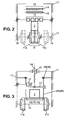
- the figure 2 is a schematic cross-sectional elevation according to 2-2, showing the various elements of the packaging plant according to the invention, at the level of the substitution conveyor system 13.
- conveyor 11 with cleats which consists of two chains 11a and 11b endless whose spacing is adjustable to take into account the size of product batches 2 and dimensions of the cutout 6.
- the apparatus 12 of the type with belts or lug chains.
- This apparatus 12 is carried by means of supports which are secured to the general frame 17 of the installation and / or the forming module 5.
- substitution conveyor system 13 in the inactive position, that is to say in a position which is located at a level substantially greater than the level of said apparatus 12.
- the figure 3 shows, in schematic cross-section according to 3-3, the installation in a configuration which allows the bare passage of batches of products 2 at the forming module 5, which module 5 is completely shunted, that is to say that it is totally inoperative.
- the chains 11a and 11b of the conveyor 11 with lugs are spaced relative to each other to make room for the substitution conveyor system 13, which conveyor system 13 is positioned at the same level as the active part of the chains 11a and 11b, acting as sole between the conveyor 7 input and the conveyor 8 output.
- the apparatus 12 retains its position above the downstream portion of the forming module 5; it can be retracted in height depending on the size of the products. In this configuration of the installation, the product batches 2 can flow freely between the input conveyor 7 and the output conveyor 8.
- the figure 4 shows, in the form of a schematic elevation, the installation according to the invention and in particular the positioning of the substitution conveying system 13, between the input conveyor 7 and the output conveyor 8.
- This substitute conveyor system 13 comprises a conveyor belt 14 which serves as an upstream conveyor belt 14 and a conveyor belt 15 which acts as a downstream conveyor belt. These two conveyor belts 14 and 15 are abutted with each other and with, respectively, the conveyor 7 input and the conveyor 8 output. They establish a continuity for the surface or sole circulation of product batches 2 between the input conveyor 7 and the output conveyor 8.
- the substitution conveying system 13 is carried on each side by a pantograph-shaped support 19 which is hinged, at its upper part, on the general frame 17 of the installation.
- the pantographs 19 carry a structure 20 on which the upstream conveyor belt 14 is installed and this structure 20 serves as a support and a guide for the frame 21 of the downstream conveyor belt 15.
- the downstream conveyor belt 15 is carried by the frame 21 but, in the active conveying position, as shown figure 4 it is wedged with respect to the frame 17 by means of vertically disposed legs 22, which feet 22 serve as a support for the downstream conveyor belt 15 and they rest on supports 23 arranged at the level of the general frame 17 for placing said conveyor belt 15 in the active position substitution, projecting downstream of the installation relative to the conveyor belt 14 upstream.
- the feet 22 are slidably mounted on the frame 21 and this frame 21 is itself guided on the structure by means of a system of slides 24 to move from the downstream to the upstream when, as shown figure 5 , the entire substitution conveyor system 13 changes from the active substitution position to the inactive position.
- the substitution conveyor system 13 actually comprises a kind of telescopic conveyor belt which consists of the upstream conveyor belt 14 and the downstream conveyor belt 15.
- the downstream conveyor belt 15 moves vertically to pass under the level of the upstream conveyor belt 14, guided by its frame 21 in which slide its feet 22 which serve as a support. This retraction of the downstream conveyor belt 15 allows the latter to position itself under the upstream conveyor belt 14 before terminating the complete retraction of this substitution conveying system 13, as represented figure 5 in strong lines.
- the pantograph system 19 comprises two arms 25 and 26 hinged together at their middle portion, forming scissors; they are articulated about a central axis 27 which is located at least at the apparatus 12, preferably substantially above.
- the arm 25 extends between a hinge 28 located at the upper part of the installation, secured to the frame 17, and a hinge 29 which is movable on a slide system 30 which extends longitudinally on the structure 20 which carries the conveyor belt 14 upstream.
- the arm 26 extends between a fixed point 31 located on the structure 20 of the conveyor belt 14 upstream and a hinge 32 which is movable, guided on a slide system 33 which is secured to the frame 17 general of the installation and / or module 5 shaping.
- the deployment or folding of the pantograph 19 is effected, for example, by means of a screw-nut system; the screw 34 being interposed between the central axis 27 of the pantograph and a nut 35, which nut 35, which is operated by appropriate means, is secured to the frame 17 generally by means of a bearing 36 mounted on a hinge 37.
- This pantograph 19 is also sketched figure 5 , showing the position of the arms 25 and 26, which arms are sufficiently spaced apart to provide a passage whose width corresponds at least to the dimensions of the batches of products to be passed through, which batches are transported by the conveyor belt 13 of conveyor substitution conveyors 14 and 15 upstream and downstream.
Landscapes
- Engineering & Computer Science (AREA)
- Mechanical Engineering (AREA)
- Auxiliary Devices For And Details Of Packaging Control (AREA)
- Intermediate Stations On Conveyors (AREA)
Claims (6)
- Vorrichtung zum Verpacken von Produktlosen (2), die über einen gemeinsamen Hauptchassis verteilt aufweist:- eine Eingangsfördereinrichtung (7), auf der die Produkte (2) als Lose angeordnet sind die von einer Vorbereitungs- und Gruppierungsstation kommen,- eine Ausgangsfördereinrichtung (8), die die Produkte (2) in Richtung einer Folienverpackmaschine (3) in Form von Losen abführt,- ein Bearbeitungsmodul (5) für eine Schalen- oder Wrap-Around-Verpackung,wobei der Bearbeitungsmodul zum einen eine Mitnehmerfördereinrichtung (11) aufweist, die aus zwei einen Boden ausbildenden Endlosketten (11a, 11b) ausgebildet ist, der sich zwischen der Eingangsfördereinrichtung (7) und der Ausgangsfördereinrichtung (8) erstreckt, wobei die Endlosketten (11a, 11b) in Querrichtung zum Verändern der Breite des Bodens einstellbar sind, und andererseits eine Einrichtung (12) zum Falten und zur Formgebung der Verpackung, die oberhalb des Endabschnitts des durch die Mitnehmerfördereinrichtung (11) gebildeten Bodens angeordnet ist,wobei die Vorrichtung ein Einfahrmittel für die Endlosketten (11a, 11b), ein Mittel zum Ermöglichen des Austauschens der Endlosketten und ein Fördersystem (13) aufweist, das angepasst ist, einen einfachen unverpackten Durchgang der Produktlose (2) zwischen der Eingangsfördereinrichtung (7) und der Ausgangsfördereinrichtung (8) zu ermöglichen, wobei sich das Austauschfördersystem (13) zwischen den Endlosketten (11a, 11b) zum Ausbilden eines zwischen der Eingangsfördereinrichtung (7) und der Ausgangsfördereinrichtung (8) fortlaufenden Bodens einfügt,
dadurch gekennzeichnet, dass das Austauschfördersystem (13) aus einer Vielzahl von Endlosförderbändern ausgebildet ist: mindestens einem stromaufwärtigen Förderband (14) und mindestens einem stromabwärtigen Förderband (15), wobei die Förderbänder (14, 15) zueinander und jeweils mit der Eingangsfördereinrichtung (7) und der Ausgangsfördereinrichtung (8) zusammenbringbar sind, wobei die stromaufwärtigen und stromabwärtigen Förderbänder den Raum zwischen der Eingangs- und Ausgangsfördereinrichtungen nach dem Einfahren der Mitnehmerfördereinrichtung (11) ausfüllen und insbesondere nach dem Auseinanderfahren der Endlosketten (11a, 11b) der Mitnehmerfördereinrichtung des Bearbeitungsmoduls (5) für Verpackungen,
und dass das Austauschfördersystem (13) mit zwei Förderbändern (14, 15) ausgebildet ist, die im Verhältnis zueinander in Längsrichtung der Laufrichtung der Produktlose (2) bewegbar sind und in einer vertikalen Richtung, wobei die Förderbänder (14, 15) im Verhältnis zueinander zwischen einer inaktiven Position, in der sie übereinander angeordnet sind, und einer aktiven Position, in der sie aneinander liegen, bewegbar sind, um den Abschnitt des Bodens auszubilden, der sich zwischen der Eingangsfördereinrichtung (7) und der Ausgangsfördereinrichtung (8) erstreckt und die Endlosketten (11a, 11b) der Mitnehmerfördereinrichtung (11) ersetzt. - Vorrichtung zum Verpacken nach Anspruch 1, dadurch gekennzeichnet, dass das Austauschfördersystem (13) vertikal bewegbar ist und auf jeder Seite durch eine Unterstützung getragen wird, die mit dem Hauptchassis (17) verbunden ist und die sich oberhalb des umlaufenden Bodens für die Produktlose (2) erstreckt, und zwar gegenüberliegend zu dem stromaufwärtigen Abschnitt der Mitnehmerfördereinrichtung (11) und stromaufwärtig zur Einrichtung (12).
- Vorrichtung zum Verpacken nach Anspruch 2, dadurch gekennzeichnet, dass jede Unterstützung des Austauschfördersystem (13) mit einem Pantographen (19) ausgebildet ist, der sich zwischen dem Hauptchassis (17) und einer Struktur (20) erstreckt, die das stromaufwärtige Förderband (14) trägt, wobei die Struktur gleichzeitig als Führung des Trageelements (21) des stromabwärtigen Förderbands (15) dient.
- Vorrichtung zum Verpacken nach Anspruch 3, dadurch gekennzeichnet, dass der Pantograph (19) Scherenarme (25, 26) aufweist, die seitlich angeordnet und ausreichend in Querrichtung beabstandet sind, um einen maximalen Raum freizulassen, der einen unverpackten Durchgang der Produktlose (2) ermöglicht, wobei die Arme (25, 26) durch ein geeignetes Mittel betrieben werden, um das Fördersystem (13) je nach Bedarf aus seiner inaktiven Position in seine aktive Position zu überführen und umgekehrt.
- Vorrichtung zum Verpacken nach Anspruch 3, dadurch gekennzeichnet, dass das stromabwärtige Förderband (15) auf einem Trageelement (21) angeordnet ist, das mittels eines Laufschienensystems (24) durch die Struktur (20) des stromaufwärtigen Förderbands (14) getragen wird, wobei das Laufschienensystem unter Wirkung des geeigneten Betriebsmittels zulässt, das stromabwärtige Förderband (15) unter dem stromaufwärtigen Förderband (14) einzuziehen, um dem Aufbau des Austauschfördersystems (13) eine Abmessung zu verleihen, die mit dem stromaufwärts zur Einrichtung (12) zur Verfügung stehenden Platz kompatibel ist, und zwar innerhalb der Abmessungen des Bearbeitungsmoduls (5).
- Vorrichtung zum Verpacken nach Anspruch 3, dadurch gekennzeichnet, dass das stromabwärtige Förderband (15) bewegbar auf dem Trageelement (21) montiert ist, und zwar zwischen einer aktiven Austauschposition, in der es sich auf dem Niveau der Ausgangsfördereinrichtung (8) befindet, und einer inaktiven Position, in der es sich unter dem Niveau des stromaufwärtigen Förderbands (14) befindet, wobei das stromabwärtige Förderband (15) im Verhältnis zum Trageelement (21) beweglich mittels Füßen (22) montiert ist, die vertikal in dem Trageelement (21) gleiten und die aktive Austauschposition mittels einer auf dem Vorrichtungschassis (17) angeordneten Auflage (23) erreicht wird, auf der die Füße (22) aufliegen.
Applications Claiming Priority (1)
| Application Number | Priority Date | Filing Date | Title |
|---|---|---|---|
| FR1056215A FR2963321B1 (fr) | 2010-07-28 | 2010-07-28 | Installation de conditionnement de lots de produits |
Publications (3)
| Publication Number | Publication Date |
|---|---|
| EP2412636A1 EP2412636A1 (de) | 2012-02-01 |
| EP2412636B1 EP2412636B1 (de) | 2012-12-12 |
| EP2412636B3 true EP2412636B3 (de) | 2013-11-06 |
Family
ID=43663641
Family Applications (1)
| Application Number | Title | Priority Date | Filing Date |
|---|---|---|---|
| EP11173722.7A Active EP2412636B3 (de) | 2010-07-28 | 2011-07-13 | Anlage zur Verpackung von Warenlosen |
Country Status (5)
| Country | Link |
|---|---|
| US (1) | US8966864B2 (de) |
| EP (1) | EP2412636B3 (de) |
| CN (1) | CN102424129B (de) |
| BR (1) | BRPI1103446A2 (de) |
| FR (1) | FR2963321B1 (de) |
Families Citing this family (24)
| Publication number | Priority date | Publication date | Assignee | Title |
|---|---|---|---|---|
| DE202010018316U1 (de) | 2010-11-08 | 2015-08-07 | Krones Aktiengesellschaft | Maschine zur Verarbeitung und/oder Verpackung von Gegenständen |
| DE102010064601B3 (de) * | 2010-11-08 | 2025-11-20 | Krones Aktiengesellschaft | Maschine zur Verarbeitung und/oder Verpackung von Gegenständen und Verfahren zum Modifizieren einer Transportstrecke dieser Maschine |
| JP5865164B2 (ja) * | 2012-04-16 | 2016-02-17 | オイレス工業株式会社 | 離間距離調整装置およびこれを用いた搬送装置 |
| DE102014112341A1 (de) | 2014-08-28 | 2016-03-03 | Krones Aktiengesellschaft | Verpackungsvorrichtung und verfahren zum modifizieren einer transportstrecke einer verpackungsvorrichtung |
| US9938031B2 (en) * | 2014-10-27 | 2018-04-10 | Standard Knapp Inc. | Method of processing a plurality of articles through a processing section of a packaging machine and method of reconfiguring a processing section of a packaging machine |
| DE102016205255A1 (de) * | 2016-03-30 | 2017-10-05 | Krones Aktiengesellschaft | Modulsystem zum Umgang mit Getränkebehältnissen und entsprechendes Verfahren hierfür |
| CN109661623A (zh) | 2016-09-09 | 2019-04-19 | 宝洁公司 | 用于在单条生产线上同时生产不同产品的方法 |
| US10442629B2 (en) | 2016-09-09 | 2019-10-15 | The Procter & Gamble Company | Vacuum holder and carrier with autonomous vacuum |
| CN109690430B (zh) | 2016-09-09 | 2022-06-24 | 宝洁公司 | 基于需求生产产品的系统和方法 |
| US10640249B2 (en) | 2016-09-09 | 2020-05-05 | The Procter & Gamble Company | Track system for creating finished products |
| EP3509979B1 (de) | 2016-09-09 | 2023-06-14 | The Procter & Gamble Company | System und verfahren zum unabhängigen lenken von fahrzeugen und zum zuführen von behältern und verschlüssen an einheitsbedienstationen |
| MX2019002780A (es) | 2016-09-09 | 2019-09-04 | Procter & Gamble | Sistema y método para llenar simultáneamente recipientes de formas y/o tamaños diferentes. |
| CN109661624B (zh) | 2016-09-09 | 2022-10-25 | 宝洁公司 | 用于独立地引导装载容器的载具以创建不同成品的系统和方法 |
| MX2019002782A (es) | 2016-09-09 | 2019-09-04 | Procter & Gamble | Sistema y método para llenar simultáneamente recipientes con diferentes composiciones de fluidos. |
| DE102016124400A1 (de) * | 2016-12-14 | 2018-06-14 | Krones Ag | Verfahren und Vorrichtung zum Erfassen von Störungen beim Objekttransport |
| DE102017203581A1 (de) * | 2017-03-06 | 2018-09-06 | Krones Aktiengesellschaft | Transportabschnitt einer Verpackungsstrecke sowie Verfahren zum Modifizieren einer für Artikel oder Zusammenstellungen an Artikeln vorgesehenen Verpackungsstrecke |
| DE102017203588B4 (de) * | 2017-03-06 | 2024-07-18 | Krones Aktiengesellschaft | Vorrichtung zum Umgang mit Artikeln sowie Verfahren zum Tauschen mindestens eines Transportmoduls und wenigstens eines Arbeitsmoduls der Vorrichtung |
| DE102017107609A1 (de) | 2017-04-10 | 2018-10-11 | Khs Gmbh | Vorrichtung und Verfahren zur Bildung von Gebinden |
| DE102017109470A1 (de) * | 2017-05-03 | 2018-11-08 | Illinois Tool Works Inc. | Verpackungsmaschine und verfahren zum verpacken von produkten |
| DE102017210405A1 (de) * | 2017-06-21 | 2018-12-27 | Krones Aktiengesellschaft | Transporteinrichtung für eine verpackungsmaschine und verfahren zum tauschen eines umlaufend geführten transportmittels innerhalb einer verpackungsmaschine |
| US11345554B2 (en) | 2018-04-10 | 2022-05-31 | The Procter & Gamble Company | Method and apparatus for flexibly assembling packages of absorbent articles |
| EP4031473A4 (de) | 2020-11-24 | 2023-09-06 | FMH Conveyors LLC | Transfereinheit mit angehobenem band |
| IT202300025146A1 (it) * | 2023-11-27 | 2025-05-27 | Ocme Srl | Macchina fardellatrice. |
| WO2025257764A1 (en) * | 2024-06-13 | 2025-12-18 | Aetna Group S.P.A. | Packaging machine |
Family Cites Families (38)
| Publication number | Priority date | Publication date | Assignee | Title |
|---|---|---|---|---|
| US2632557A (en) * | 1950-10-16 | 1953-03-24 | Lindberg Bror Allan | Portable supporting device for conveyers |
| US3243033A (en) * | 1964-02-18 | 1966-03-29 | Package Machinery Co | Machines employing article raising elevators |
| DE2035874A1 (de) * | 1970-07-20 | 1972-01-27 | Wollenhaupt A | Baukastensystem für Werkzeugmaschinen und Fertigungsstraßen |
| US3739904A (en) * | 1971-10-20 | 1973-06-19 | Continental Can Co | Modular conveyor support assembly |
| US4194633A (en) * | 1977-09-12 | 1980-03-25 | Raytheon Company | Adjustable conveyor |
| US4709531A (en) * | 1984-05-23 | 1987-12-01 | Teraoka Seiko Co., Ltd. | Stretch film packaging machine |
| US4643299A (en) * | 1984-06-07 | 1987-02-17 | Caljan A/S | Telescopic belt conveyor |
| DE3615064A1 (de) * | 1986-05-03 | 1987-11-05 | Bosch Gmbh Robert | Foerdereinrichtung zum transport von werkstuecken |
| US4925009A (en) * | 1987-11-02 | 1990-05-15 | Aec Machinery Limited | Portable conveyor |
| IT227686Y1 (it) * | 1992-11-20 | 1997-12-15 | Hitech Systems Srl | Convogliatore per lo smaltimento di generici prodotti a macchine con- fezionatrici o inscatolatrici |
| US5421446A (en) * | 1993-03-12 | 1995-06-06 | United Parcel Service Of America, Inc. | Article diverter apparatus for use in conveyor systems |
| GB9506541D0 (en) * | 1995-03-30 | 1995-05-17 | Mead Corp | Packaging machine for beverage multi-packs |
| US5823316A (en) * | 1995-10-04 | 1998-10-20 | Motorola, Inc. | Method for automatic conveyor width adjustment |
| US6012568A (en) * | 1996-03-15 | 2000-01-11 | Kane; Joseph R. | Adjustable conveyor |
| US5813518A (en) * | 1996-05-03 | 1998-09-29 | Odawara Automation, Inc. | Conveyor system |
| IT1299962B1 (it) * | 1998-04-07 | 2000-04-04 | Baumer Srl | Metodo e macchina per imballare oggetti mediante spezzoni di materiale in foglio ottenuti da un nastro continuo. |
| US6607066B1 (en) * | 1998-07-10 | 2003-08-19 | Crisplant A/S | Conveyor |
| US6484475B1 (en) * | 1999-02-02 | 2002-11-26 | Kisters Kayat, Inc. | Modular packaging machine |
| US6427831B1 (en) * | 1999-11-19 | 2002-08-06 | Frank B. Norton | Convertible conveyor bed and method |
| US6409011B1 (en) * | 2000-05-24 | 2002-06-25 | Precision Handling Devices, Inc. | Gate conveyor |
| US6688458B2 (en) * | 2001-10-09 | 2004-02-10 | Speedline Technologies, Inc. | System and method for controlling a conveyor system configuration to accommodate different size substrates |
| US6588173B1 (en) * | 2002-02-21 | 2003-07-08 | Illinois Tool Works Inc. | Machine for packaging containers |
| WO2003078282A1 (de) * | 2002-03-15 | 2003-09-25 | Siemens Aktiengesellschaft | Breitenverstellbare fördereinrichtung zum transportieren von werkstücken |
| ITBO20020614A1 (it) * | 2002-09-30 | 2004-04-01 | Baumer Srl | Metodo operativo per una macchina imballatrice del tipo |
| US20040083689A1 (en) * | 2002-10-31 | 2004-05-06 | Floding Daniel Leonard | Methods and apparatus for adjustable wrapping |
| ITBO20020693A1 (it) * | 2002-11-04 | 2004-05-05 | Baumer Srl | Sistema di macchina imballatrice, del tipo a manica, |
| US7909153B2 (en) * | 2004-06-18 | 2011-03-22 | Pogue Richard W | Extendible conveyor system |
| DE202005018076U1 (de) | 2005-11-18 | 2007-03-29 | Seho Systemtechnik Gmbh | Stützvorrichtung einer Transportvorrichtung einer Lötanlage |
| US7650729B2 (en) * | 2006-09-08 | 2010-01-26 | Tipper Tie, Inc. | Telescoping conveyor mechanisms that cooperate with packaging systems having clippers and related methods |
| US7810788B2 (en) * | 2006-09-12 | 2010-10-12 | Flexible Steel Lacing Company | Belt lifter apparatus |
| US7328554B1 (en) * | 2006-10-18 | 2008-02-12 | Alain Cerf | Adjustable height film wrapping machine |
| US7918332B2 (en) * | 2007-06-29 | 2011-04-05 | Chrysler Group Llc | Cantilever roll-up conveyor arrangement |
| US7941990B2 (en) * | 2009-01-06 | 2011-05-17 | Pi-Wi Beheer B.V. | Apparatus for packaging products into a container |
| US7909159B1 (en) * | 2009-08-10 | 2011-03-22 | Honda Motor Co., Ltd. | Adjustable multi-lane conveyor |
| US8356456B2 (en) * | 2010-03-04 | 2013-01-22 | Douglas Machine Inc. | Apparatus for adjustable wrapping |
| DE102010015865A1 (de) * | 2010-03-09 | 2011-09-15 | Krones Ag | Vorrichtung und Verfahren zum Verpacken von Artikeln |
| US8944239B2 (en) * | 2010-10-26 | 2015-02-03 | Engineered Lifting Systems & Equipment Inc. | Conveyor apparatus for loading or unloading packages from shipping containers |
| US8684171B1 (en) * | 2012-07-10 | 2014-04-01 | Bouldin Corporation | Modular conveyor |
-
2010
- 2010-07-28 FR FR1056215A patent/FR2963321B1/fr active Active
-
2011
- 2011-07-13 EP EP11173722.7A patent/EP2412636B3/de active Active
- 2011-07-20 US US13/186,693 patent/US8966864B2/en active Active
- 2011-07-26 CN CN201110220464.XA patent/CN102424129B/zh active Active
- 2011-07-26 BR BRPI1103446-7A patent/BRPI1103446A2/pt not_active IP Right Cessation
Also Published As
| Publication number | Publication date |
|---|---|
| BRPI1103446A2 (pt) | 2012-12-25 |
| US20120023866A1 (en) | 2012-02-02 |
| FR2963321B1 (fr) | 2012-08-17 |
| EP2412636B1 (de) | 2012-12-12 |
| FR2963321A1 (fr) | 2012-02-03 |
| CN102424129A (zh) | 2012-04-25 |
| CN102424129B (zh) | 2015-03-11 |
| US8966864B2 (en) | 2015-03-03 |
| EP2412636A1 (de) | 2012-02-01 |
Similar Documents
| Publication | Publication Date | Title |
|---|---|---|
| EP2412636B1 (de) | Anlage zur Verpackung von Warenlosen | |
| FR2943643A1 (fr) | Palettiseur avec preparation de couches de caisses | |
| FR2950615A1 (fr) | Chaine de dechargement de palettes | |
| EP3732121A1 (de) | Transfer von produkten zwischen einer durchgangszone und einer sammelfläche | |
| EP0645309B1 (de) | Verfahren und Vorrichtung zur Anpassung der Höhe einer Verpackung an die Höhe ihres Inhalts und Schneidevorrichtung dafür | |
| WO2021052961A1 (fr) | Dispositif et procede de formage de conteneur par pliage | |
| EP2490965B1 (de) | Vorrichtung zur herstellung von produktchargen zu ihrer abfüllung in behältnisse | |
| EP1973819B1 (de) | Verfahren und gruppierstation für einen palettierer | |
| FR2855147A1 (fr) | Procede et unite pour emballer des groupes de produits | |
| EP2772457A1 (de) | Hilfsanlage zur Verpackung von Artikeln | |
| FR2891264A1 (fr) | Mecanisme d'evacuation destine a une machine d'inspection de verre de type distributeur en etoile | |
| FR3072949A1 (fr) | Etuyeuse et procede d'etuyage | |
| EP0288371A1 (de) | Apparat zur automatischen Entfernung einer Gruppe von zu behandelnden Gegenständen, von deren mindestens einer fehlt oder mangelhaft ist | |
| FR2935963A1 (fr) | Dispositif de manutention de plaques en carton. | |
| EP1361183B1 (de) | Speicherförderer | |
| EP0267863B1 (de) | Automatische Verpackungsmaschine für Flaschen in einzelnen Hülsen | |
| EP0257161A1 (de) | Maschine zum Anbringen und Verriegeln von Verpackungskartons auf einer Behältergruppe | |
| FR2750967A1 (fr) | Dispositif de transfert de recipients tels que bouteilles ou analogues d'un convoyeur sur un autre | |
| FR2884506A1 (fr) | Dispositif d'entrainement pour convoyeurs ou transporteurs de charges | |
| FR3164991A1 (fr) | Dispositif de poussée et convoyeur de caisses cartonnées, ainsi que l'installation de conditionnement de produits | |
| FR2669604A1 (fr) | Dispositif de banderolage pour colis. | |
| EP1220807A1 (de) | Fördervorrichtung für hohl-verpackungen in einer automatischen behandlungsstrasse | |
| FR2711353A1 (fr) | Dispositif de conditionnement automatique, dans des boîtes non compartimentées, de produits alimentaires, ou autres. | |
| FR2734799A1 (fr) | Installation de redressement de recipients presentant une tete plus grande que le corps et le pied | |
| FR2773778A1 (fr) | Caisse de section ajustee au contenu, flan necessaire et dispositif d'encaissage utilisant notamment ladite caisse |
Legal Events
| Date | Code | Title | Description |
|---|---|---|---|
| AK | Designated contracting states |
Kind code of ref document: A1 Designated state(s): AL AT BE BG CH CY CZ DE DK EE ES FI FR GB GR HR HU IE IS IT LI LT LU LV MC MK MT NL NO PL PT RO RS SE SI SK SM TR |
|
| AX | Request for extension of the european patent |
Extension state: BA ME |
|
| PUAI | Public reference made under article 153(3) epc to a published international application that has entered the european phase |
Free format text: ORIGINAL CODE: 0009012 |
|
| GRAP | Despatch of communication of intention to grant a patent |
Free format text: ORIGINAL CODE: EPIDOSNIGR1 |
|
| 17P | Request for examination filed |
Effective date: 20120615 |
|
| RIC1 | Information provided on ipc code assigned before grant |
Ipc: B65B 59/00 20060101AFI20120706BHEP Ipc: B65G 21/00 20060101ALI20120706BHEP Ipc: B65B 65/00 20060101ALI20120706BHEP |
|
| GRAS | Grant fee paid |
Free format text: ORIGINAL CODE: EPIDOSNIGR3 |
|
| GRAA | (expected) grant |
Free format text: ORIGINAL CODE: 0009210 |
|
| AK | Designated contracting states |
Kind code of ref document: B1 Designated state(s): AL AT BE BG CH CY CZ DE DK EE ES FI FR GB GR HR HU IE IS IT LI LT LU LV MC MK MT NL NO PL PT RO RS SE SI SK SM TR |
|
| REG | Reference to a national code |
Ref country code: GB Ref legal event code: FG4D Free format text: NOT ENGLISH |
|
| REG | Reference to a national code |
Ref country code: CH Ref legal event code: EP |
|
| REG | Reference to a national code |
Ref country code: AT Ref legal event code: REF Ref document number: 588202 Country of ref document: AT Kind code of ref document: T Effective date: 20121215 |
|
| REG | Reference to a national code |
Ref country code: IE Ref legal event code: FG4D Free format text: LANGUAGE OF EP DOCUMENT: FRENCH |
|
| REG | Reference to a national code |
Ref country code: DE Ref legal event code: R096 Ref document number: 602011000581 Country of ref document: DE Effective date: 20130207 |
|
| PG25 | Lapsed in a contracting state [announced via postgrant information from national office to epo] |
Ref country code: ES Free format text: LAPSE BECAUSE OF FAILURE TO SUBMIT A TRANSLATION OF THE DESCRIPTION OR TO PAY THE FEE WITHIN THE PRESCRIBED TIME-LIMIT Effective date: 20130323 Ref country code: SE Free format text: LAPSE BECAUSE OF FAILURE TO SUBMIT A TRANSLATION OF THE DESCRIPTION OR TO PAY THE FEE WITHIN THE PRESCRIBED TIME-LIMIT Effective date: 20121212 Ref country code: FI Free format text: LAPSE BECAUSE OF FAILURE TO SUBMIT A TRANSLATION OF THE DESCRIPTION OR TO PAY THE FEE WITHIN THE PRESCRIBED TIME-LIMIT Effective date: 20121212 Ref country code: NO Free format text: LAPSE BECAUSE OF FAILURE TO SUBMIT A TRANSLATION OF THE DESCRIPTION OR TO PAY THE FEE WITHIN THE PRESCRIBED TIME-LIMIT Effective date: 20130312 Ref country code: LT Free format text: LAPSE BECAUSE OF FAILURE TO SUBMIT A TRANSLATION OF THE DESCRIPTION OR TO PAY THE FEE WITHIN THE PRESCRIBED TIME-LIMIT Effective date: 20121212 |
|
| REG | Reference to a national code |
Ref country code: NL Ref legal event code: VDEP Effective date: 20121212 |
|
| REG | Reference to a national code |
Ref country code: AT Ref legal event code: MK05 Ref document number: 588202 Country of ref document: AT Kind code of ref document: T Effective date: 20121212 |
|
| REG | Reference to a national code |
Ref country code: LT Ref legal event code: MG4D |
|
| PG25 | Lapsed in a contracting state [announced via postgrant information from national office to epo] |
Ref country code: GR Free format text: LAPSE BECAUSE OF FAILURE TO SUBMIT A TRANSLATION OF THE DESCRIPTION OR TO PAY THE FEE WITHIN THE PRESCRIBED TIME-LIMIT Effective date: 20130313 Ref country code: LV Free format text: LAPSE BECAUSE OF FAILURE TO SUBMIT A TRANSLATION OF THE DESCRIPTION OR TO PAY THE FEE WITHIN THE PRESCRIBED TIME-LIMIT Effective date: 20121212 Ref country code: SI Free format text: LAPSE BECAUSE OF FAILURE TO SUBMIT A TRANSLATION OF THE DESCRIPTION OR TO PAY THE FEE WITHIN THE PRESCRIBED TIME-LIMIT Effective date: 20121212 |
|
| REG | Reference to a national code |
Ref country code: DE Ref legal event code: R055 Ref document number: 602011000581 Country of ref document: DE |
|
| PG25 | Lapsed in a contracting state [announced via postgrant information from national office to epo] |
Ref country code: BG Free format text: LAPSE BECAUSE OF FAILURE TO SUBMIT A TRANSLATION OF THE DESCRIPTION OR TO PAY THE FEE WITHIN THE PRESCRIBED TIME-LIMIT Effective date: 20130312 Ref country code: RS Free format text: LAPSE BECAUSE OF FAILURE TO SUBMIT A TRANSLATION OF THE DESCRIPTION OR TO PAY THE FEE WITHIN THE PRESCRIBED TIME-LIMIT Effective date: 20121212 Ref country code: IS Free format text: LAPSE BECAUSE OF FAILURE TO SUBMIT A TRANSLATION OF THE DESCRIPTION OR TO PAY THE FEE WITHIN THE PRESCRIBED TIME-LIMIT Effective date: 20130412 Ref country code: AT Free format text: LAPSE BECAUSE OF FAILURE TO SUBMIT A TRANSLATION OF THE DESCRIPTION OR TO PAY THE FEE WITHIN THE PRESCRIBED TIME-LIMIT Effective date: 20121212 Ref country code: SK Free format text: LAPSE BECAUSE OF FAILURE TO SUBMIT A TRANSLATION OF THE DESCRIPTION OR TO PAY THE FEE WITHIN THE PRESCRIBED TIME-LIMIT Effective date: 20121212 Ref country code: CZ Free format text: LAPSE BECAUSE OF FAILURE TO SUBMIT A TRANSLATION OF THE DESCRIPTION OR TO PAY THE FEE WITHIN THE PRESCRIBED TIME-LIMIT Effective date: 20121212 Ref country code: EE Free format text: LAPSE BECAUSE OF FAILURE TO SUBMIT A TRANSLATION OF THE DESCRIPTION OR TO PAY THE FEE WITHIN THE PRESCRIBED TIME-LIMIT Effective date: 20121212 |
|
| PLCP | Request for limitation filed |
Free format text: ORIGINAL CODE: EPIDOSNLIM1 |
|
| PLCQ | Request for limitation of patent found admissible |
Free format text: ORIGINAL CODE: 0009231 |
|
| PLCR | Communication despatched that request for limitation of patent was allowed |
Free format text: ORIGINAL CODE: 0009245 |
|
| PG25 | Lapsed in a contracting state [announced via postgrant information from national office to epo] |
Ref country code: PT Free format text: LAPSE BECAUSE OF FAILURE TO SUBMIT A TRANSLATION OF THE DESCRIPTION OR TO PAY THE FEE WITHIN THE PRESCRIBED TIME-LIMIT Effective date: 20130412 Ref country code: RO Free format text: LAPSE BECAUSE OF FAILURE TO SUBMIT A TRANSLATION OF THE DESCRIPTION OR TO PAY THE FEE WITHIN THE PRESCRIBED TIME-LIMIT Effective date: 20121212 Ref country code: PL Free format text: LAPSE BECAUSE OF FAILURE TO SUBMIT A TRANSLATION OF THE DESCRIPTION OR TO PAY THE FEE WITHIN THE PRESCRIBED TIME-LIMIT Effective date: 20121212 Ref country code: NL Free format text: LAPSE BECAUSE OF FAILURE TO SUBMIT A TRANSLATION OF THE DESCRIPTION OR TO PAY THE FEE WITHIN THE PRESCRIBED TIME-LIMIT Effective date: 20121212 |
|
| LIM1 | Request for limitation found admissible |
Free format text: SEQUENCE NO: 1; FILED DURING OPPOSITION PERIOD Filing date: 20130725 Effective date: 20130725 |
|
| PLCN | Payment of fee for limitation of patent |
Free format text: ORIGINAL CODE: EPIDOSNRAL3 |
|
| PUAM | (expected) publication of b3 document |
Free format text: ORIGINAL CODE: 0009410 |
|
| STAA | Information on the status of an ep patent application or granted ep patent |
Free format text: STATUS: THE PATENT HAS BEEN LIMITED |
|
| PLBE | No opposition filed within time limit |
Free format text: ORIGINAL CODE: 0009261 |
|
| PG25 | Lapsed in a contracting state [announced via postgrant information from national office to epo] |
Ref country code: DK Free format text: LAPSE BECAUSE OF FAILURE TO SUBMIT A TRANSLATION OF THE DESCRIPTION OR TO PAY THE FEE WITHIN THE PRESCRIBED TIME-LIMIT Effective date: 20121212 |
|
| REG | Reference to a national code |
Ref country code: DE Ref legal event code: R056 Ref document number: 602011000581 Country of ref document: DE Effective date: 20130827 |
|
| REG | Reference to a national code |
Ref country code: CH Ref legal event code: AELM |
|
| 26N | No opposition filed |
Effective date: 20130913 |
|
| PG25 | Lapsed in a contracting state [announced via postgrant information from national office to epo] |
Ref country code: CY Free format text: LAPSE BECAUSE OF FAILURE TO SUBMIT A TRANSLATION OF THE DESCRIPTION OR TO PAY THE FEE WITHIN THE PRESCRIBED TIME-LIMIT Effective date: 20121212 Ref country code: HR Free format text: LAPSE BECAUSE OF FAILURE TO SUBMIT A TRANSLATION OF THE DESCRIPTION OR TO PAY THE FEE WITHIN THE PRESCRIBED TIME-LIMIT Effective date: 20121212 |
|
| REG | Reference to a national code |
Ref country code: DE Ref legal event code: R097 Ref document number: 602011000581 Country of ref document: DE Effective date: 20130913 |
|
| BERE | Be: lapsed |
Owner name: SIDEL PARTICIPATIONS Effective date: 20130731 |
|
| PG25 | Lapsed in a contracting state [announced via postgrant information from national office to epo] |
Ref country code: MC Free format text: LAPSE BECAUSE OF FAILURE TO SUBMIT A TRANSLATION OF THE DESCRIPTION OR TO PAY THE FEE WITHIN THE PRESCRIBED TIME-LIMIT Effective date: 20121212 |
|
| REG | Reference to a national code |
Ref country code: IE Ref legal event code: MM4A |
|
| PG25 | Lapsed in a contracting state [announced via postgrant information from national office to epo] |
Ref country code: BE Free format text: LAPSE BECAUSE OF NON-PAYMENT OF DUE FEES Effective date: 20130731 |
|
| PG25 | Lapsed in a contracting state [announced via postgrant information from national office to epo] |
Ref country code: LV Free format text: LAPSE BECAUSE OF FAILURE TO SUBMIT A TRANSLATION OF THE DESCRIPTION OR TO PAY THE FEE WITHIN THE PRESCRIBED TIME-LIMIT Effective date: 20131106 |
|
| PG25 | Lapsed in a contracting state [announced via postgrant information from national office to epo] |
Ref country code: IE Free format text: LAPSE BECAUSE OF NON-PAYMENT OF DUE FEES Effective date: 20130713 |
|
| REG | Reference to a national code |
Ref country code: CH Ref legal event code: PL |
|
| PG25 | Lapsed in a contracting state [announced via postgrant information from national office to epo] |
Ref country code: CH Free format text: LAPSE BECAUSE OF NON-PAYMENT OF DUE FEES Effective date: 20140731 Ref country code: LI Free format text: LAPSE BECAUSE OF NON-PAYMENT OF DUE FEES Effective date: 20140731 |
|
| PG25 | Lapsed in a contracting state [announced via postgrant information from national office to epo] |
Ref country code: SM Free format text: LAPSE BECAUSE OF FAILURE TO SUBMIT A TRANSLATION OF THE DESCRIPTION OR TO PAY THE FEE WITHIN THE PRESCRIBED TIME-LIMIT Effective date: 20121212 |
|
| REG | Reference to a national code |
Ref country code: FR Ref legal event code: PLFP Year of fee payment: 5 |
|
| PG25 | Lapsed in a contracting state [announced via postgrant information from national office to epo] |
Ref country code: TR Free format text: LAPSE BECAUSE OF FAILURE TO SUBMIT A TRANSLATION OF THE DESCRIPTION OR TO PAY THE FEE WITHIN THE PRESCRIBED TIME-LIMIT Effective date: 20121212 Ref country code: MT Free format text: LAPSE BECAUSE OF FAILURE TO SUBMIT A TRANSLATION OF THE DESCRIPTION OR TO PAY THE FEE WITHIN THE PRESCRIBED TIME-LIMIT Effective date: 20121212 |
|
| PG25 | Lapsed in a contracting state [announced via postgrant information from national office to epo] |
Ref country code: MK Free format text: LAPSE BECAUSE OF FAILURE TO SUBMIT A TRANSLATION OF THE DESCRIPTION OR TO PAY THE FEE WITHIN THE PRESCRIBED TIME-LIMIT Effective date: 20121212 Ref country code: LU Free format text: LAPSE BECAUSE OF NON-PAYMENT OF DUE FEES Effective date: 20130713 Ref country code: HU Free format text: LAPSE BECAUSE OF FAILURE TO SUBMIT A TRANSLATION OF THE DESCRIPTION OR TO PAY THE FEE WITHIN THE PRESCRIBED TIME-LIMIT; INVALID AB INITIO Effective date: 20110713 |
|
| GBPC | Gb: european patent ceased through non-payment of renewal fee |
Effective date: 20150713 |
|
| PG25 | Lapsed in a contracting state [announced via postgrant information from national office to epo] |
Ref country code: GB Free format text: LAPSE BECAUSE OF NON-PAYMENT OF DUE FEES Effective date: 20150713 |
|
| REG | Reference to a national code |
Ref country code: FR Ref legal event code: PLFP Year of fee payment: 6 |
|
| REG | Reference to a national code |
Ref country code: FR Ref legal event code: PLFP Year of fee payment: 7 |
|
| REG | Reference to a national code |
Ref country code: FR Ref legal event code: PLFP Year of fee payment: 8 |
|
| PG25 | Lapsed in a contracting state [announced via postgrant information from national office to epo] |
Ref country code: AL Free format text: LAPSE BECAUSE OF FAILURE TO SUBMIT A TRANSLATION OF THE DESCRIPTION OR TO PAY THE FEE WITHIN THE PRESCRIBED TIME-LIMIT Effective date: 20121212 |
|
| P01 | Opt-out of the competence of the unified patent court (upc) registered |
Effective date: 20230418 |
|
| PGFP | Annual fee paid to national office [announced via postgrant information from national office to epo] |
Ref country code: FR Payment date: 20250620 Year of fee payment: 15 |
|
| PGFP | Annual fee paid to national office [announced via postgrant information from national office to epo] |
Ref country code: DE Payment date: 20250620 Year of fee payment: 15 |
|
| PGFP | Annual fee paid to national office [announced via postgrant information from national office to epo] |
Ref country code: IT Payment date: 20250619 Year of fee payment: 15 |