EP2410102A2 - Bausteinsystem, insbesondere zur Erstellung von Bauwerken - Google Patents
Bausteinsystem, insbesondere zur Erstellung von Bauwerken Download PDFInfo
- Publication number
- EP2410102A2 EP2410102A2 EP11167200A EP11167200A EP2410102A2 EP 2410102 A2 EP2410102 A2 EP 2410102A2 EP 11167200 A EP11167200 A EP 11167200A EP 11167200 A EP11167200 A EP 11167200A EP 2410102 A2 EP2410102 A2 EP 2410102A2
- Authority
- EP
- European Patent Office
- Prior art keywords
- plastic
- block system
- building block
- block
- building
- Prior art date
- Legal status (The legal status is an assumption and is not a legal conclusion. Google has not performed a legal analysis and makes no representation as to the accuracy of the status listed.)
- Granted
Links
- 238000010276 construction Methods 0.000 title claims description 7
- 239000004033 plastic Substances 0.000 claims abstract description 24
- 229920003023 plastic Polymers 0.000 claims abstract description 24
- -1 polyethylene terephthalate Polymers 0.000 claims abstract description 8
- 239000004734 Polyphenylene sulfide Substances 0.000 claims abstract description 7
- 229920001707 polybutylene terephthalate Polymers 0.000 claims abstract description 7
- 229920000139 polyethylene terephthalate Polymers 0.000 claims abstract description 7
- 239000005020 polyethylene terephthalate Substances 0.000 claims abstract description 7
- 229920000069 polyphenylene sulfide Polymers 0.000 claims abstract description 7
- 238000001746 injection moulding Methods 0.000 claims description 6
- 230000000295 complement effect Effects 0.000 claims description 3
- 238000001125 extrusion Methods 0.000 claims description 3
- 239000011449 brick Substances 0.000 description 21
- 238000004519 manufacturing process Methods 0.000 description 11
- 239000004927 clay Substances 0.000 description 5
- 229920001817 Agar Polymers 0.000 description 4
- 239000011505 plaster Substances 0.000 description 4
- XLYOFNOQVPJJNP-UHFFFAOYSA-N water Substances O XLYOFNOQVPJJNP-UHFFFAOYSA-N 0.000 description 4
- 238000005520 cutting process Methods 0.000 description 3
- 239000011451 fired brick Substances 0.000 description 3
- 238000010304 firing Methods 0.000 description 3
- 238000009434 installation Methods 0.000 description 3
- 238000001035 drying Methods 0.000 description 2
- 230000007613 environmental effect Effects 0.000 description 2
- 238000000034 method Methods 0.000 description 2
- 239000002994 raw material Substances 0.000 description 2
- 238000010521 absorption reaction Methods 0.000 description 1
- 239000011230 binding agent Substances 0.000 description 1
- 239000000969 carrier Substances 0.000 description 1
- 239000011248 coating agent Substances 0.000 description 1
- 238000000576 coating method Methods 0.000 description 1
- 239000002131 composite material Substances 0.000 description 1
- 239000004567 concrete Substances 0.000 description 1
- 238000011161 development Methods 0.000 description 1
- 230000018109 developmental process Effects 0.000 description 1
- 238000005265 energy consumption Methods 0.000 description 1
- 238000011049 filling Methods 0.000 description 1
- 230000037406 food intake Effects 0.000 description 1
- 239000008187 granular material Substances 0.000 description 1
- 230000002209 hydrophobic effect Effects 0.000 description 1
- 238000009776 industrial production Methods 0.000 description 1
- 229910052500 inorganic mineral Inorganic materials 0.000 description 1
- 239000012774 insulation material Substances 0.000 description 1
- 239000000463 material Substances 0.000 description 1
- 239000002184 metal Substances 0.000 description 1
- 239000011707 mineral Substances 0.000 description 1
- 239000000203 mixture Substances 0.000 description 1
- 239000011454 mudbrick Substances 0.000 description 1
- 239000003973 paint Substances 0.000 description 1
- 238000001556 precipitation Methods 0.000 description 1
- 239000004575 stone Substances 0.000 description 1
Images


Classifications
-
- E—FIXED CONSTRUCTIONS
- E04—BUILDING
- E04C—STRUCTURAL ELEMENTS; BUILDING MATERIALS
- E04C1/00—Building elements of block or other shape for the construction of parts of buildings
-
- E—FIXED CONSTRUCTIONS
- E04—BUILDING
- E04B—GENERAL BUILDING CONSTRUCTIONS; WALLS, e.g. PARTITIONS; ROOFS; FLOORS; CEILINGS; INSULATION OR OTHER PROTECTION OF BUILDINGS
- E04B2/00—Walls, e.g. partitions, for buildings; Wall construction with regard to insulation; Connections specially adapted to walls
- E04B2/02—Walls, e.g. partitions, for buildings; Wall construction with regard to insulation; Connections specially adapted to walls built-up from layers of building elements
- E04B2/14—Walls having cavities in, but not between, the elements, i.e. each cavity being enclosed by at least four sides forming part of one single element
- E04B2/16—Walls having cavities in, but not between, the elements, i.e. each cavity being enclosed by at least four sides forming part of one single element using elements having specially-designed means for stabilising the position
- E04B2/18—Walls having cavities in, but not between, the elements, i.e. each cavity being enclosed by at least four sides forming part of one single element using elements having specially-designed means for stabilising the position by interlocking of projections or inserts with indentations, e.g. of tongues, grooves, dovetails
-
- E—FIXED CONSTRUCTIONS
- E04—BUILDING
- E04C—STRUCTURAL ELEMENTS; BUILDING MATERIALS
- E04C1/00—Building elements of block or other shape for the construction of parts of buildings
- E04C1/39—Building elements of block or other shape for the construction of parts of buildings characterised by special adaptations, e.g. serving for locating conduits, for forming soffits, cornices, or shelves, for fixing wall-plates or door-frames, for claustra
- E04C1/397—Building elements of block or other shape for the construction of parts of buildings characterised by special adaptations, e.g. serving for locating conduits, for forming soffits, cornices, or shelves, for fixing wall-plates or door-frames, for claustra serving for locating conduits
-
- E—FIXED CONSTRUCTIONS
- E04—BUILDING
- E04B—GENERAL BUILDING CONSTRUCTIONS; WALLS, e.g. PARTITIONS; ROOFS; FLOORS; CEILINGS; INSULATION OR OTHER PROTECTION OF BUILDINGS
- E04B2/00—Walls, e.g. partitions, for buildings; Wall construction with regard to insulation; Connections specially adapted to walls
- E04B2/02—Walls, e.g. partitions, for buildings; Wall construction with regard to insulation; Connections specially adapted to walls built-up from layers of building elements
- E04B2002/0202—Details of connections
- E04B2002/0204—Non-undercut connections, e.g. tongue and groove connections
- E04B2002/0206—Non-undercut connections, e.g. tongue and groove connections of rectangular shape
-
- E—FIXED CONSTRUCTIONS
- E04—BUILDING
- E04B—GENERAL BUILDING CONSTRUCTIONS; WALLS, e.g. PARTITIONS; ROOFS; FLOORS; CEILINGS; INSULATION OR OTHER PROTECTION OF BUILDINGS
- E04B2/00—Walls, e.g. partitions, for buildings; Wall construction with regard to insulation; Connections specially adapted to walls
- E04B2/02—Walls, e.g. partitions, for buildings; Wall construction with regard to insulation; Connections specially adapted to walls built-up from layers of building elements
- E04B2002/0202—Details of connections
- E04B2002/0232—Undercut connections, e.g. using undercut tongues and grooves
Definitions
- the invention relates to a modular system, in particular for the construction of buildings.
- bricks are typically made in an industrial way of clay or clay.
- the bricks can be fired or dried.
- the bricks get their shape mostly by bar presses and can be cut in this process.
- bar-pressed bricks also have very smooth surfaces.
- rustic shaped bricks are manufactured in industrial production by mechanically inserting the clay mass into molds.
- Air-dried bricks so-called Adoben
- Such air-dried bricks are also referred to as mud bricks.
- Burnt bricks are baked in the kiln.
- These bricks are permanently solidified in air-dried bricks, but are not very weather-resistant, as the fired bricks have a high porosity and water absorption capacity.
- Such fired bricks are used indoors for building purposes or usually covered with plaster on the finished structure.
- Hardburned bricks are fired at higher temperatures, making them harder and denser than bricks fired at low temperature. This type of brick is used outdoors in particular. These include, among others, facing bricks, clinker and roof tiles.
- the corresponding structures are usually erected by juxtaposing and superimposing individual loose building blocks, typically also employing a binder for bonding the building blocks.
- Various brick sizes and geometries are known in the art.
- larger units such. B. entire wall parts made of concrete, are used. In the production, transport and installation of these units, however, suitable load carriers are to be provided.
- Bindmitte The building blocks of small and medium-sized bricks as well as larger wall parts are complex to produce, require a high level of expert knowledge and skills in the installation and must be held together by Bindmitte.
- the material of these components is brittle and in particular also has significant disadvantages in the occurrence of water and moisture.
- To protect the building blocks and to produce an individually desired surface property of the structures must have a Coating z. B. be used by a plaster, a wallpaper or a paint or a color.
- the present invention has for its object to improve a block system of the type mentioned, in particular, a cost-effective and resource-saving production and longevity of the blocks should be guaranteed.
- a modular system in particular for the construction of structures, in which a plurality of substantially formed plastic, modular composite blocks are present, which are provided for mutual fixation at the top and / or at the bottom with at least one connecting element.
- the inventive measures a cost-effective, stable and durable modular system is created.
- the building blocks are environmentally friendly to manufacture, quick and easy to install and can have individual color and surface properties. It provides blocks with a special geometry and thereby allows a quick and easy shoring, with individual adjustments such. B. color or desired surface structures can be realized.
- the mentioned disadvantages of the prior art such as the high energy consumption in the production, the necessary high level of expertise in handling and the limitation of the application, do not occur in the building blocks according to the invention.
- the at least one connecting element of a module can be formed as part of a positive connection in the form of an elongated recess, in particular a groove or an elongate projection, in particular a rib and engageable with a corresponding complementary formed connecting element of another module. This allows the individual blocks are stacked in a simple manner one above the other.
- the connecting elements may face each other
- the raw material of the building blocks used can be a high-performance plastic, such as.
- a high-performance plastic such as.
- PET polyethylene terephthalate
- PPS polyphenylene sulfide
- PBT polybutylene terephthalate
- the plastic of the building blocks may at least partially comprise recycled plastic.
- the at least one connecting element may be integral with the composable building blocks.
- the base body has at least one of the modules through-holes.
- the at least one edge of at least one of the building blocks may have a chamfer, i. H. one or more edges may have cut-off surfaces or be rounded.
- the module can be produced in an advantageous manner by an injection molding process or by extrusion. During injection molding, the plastic components cool down automatically after production and can be used after just a few seconds.
- At least one side surface of at least one of the building blocks may be at least partially roughened. Under side surfaces are here in particular visible surfaces, which do not face other building blocks to understand.
- the building blocks may advantageously be at least partially provided with roughened surfaces in order to facilitate or facilitate the application of mineral plaster.
- the method provides to produce cost-effective, stable and durable plastic building blocks.
- the building blocks are not made of clay or clay, but of high-strength and temperature-resistant high-performance plastics. In production, these are not formed by deep drawing of plastic plates, but produced in a resource-saving manner by a conventional injection molding process.
- a metal mold which is located in the injection molding machine, the pre-dried plastic granulate is "shot" directly into the mold via cylinders and screws and can be given its final shape depending on the filling and holding pressure.
- the building blocks either use the plastic of recycled products or they can easily be recycled after use.
- a plastic component for the modular system according to the invention is specified in claim 11.
- the block is heat-resistant, UV-stable, fireproof, impact-resistant, resistant to stress cracks, biodegradable, impermeable to water (hydrophobic), heat-insulating and not least dimensionally stable.
- These building blocks must be due to their stability and resistance can not be protected by a plaster from environmental influences.
- the building blocks can thus also be used, for example, for basements in flood areas.
- the color and / or the surface shape of the plastic tiles can be individually designed according to customer requirements and produced by a batch addition (color).
- the load capacity of these components is the requirement of 500 kg / cm 2 immediately after production.
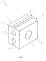
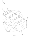
- FIG. 1 shows a building block 1.1 of a building block system according to the invention for the construction of buildings (not shown) in a first embodiment.
- the modular system according to the invention is formed by a plurality of substantially or in the present embodiment, completely made of plastic, especially high-performance plastic, preferably polyethylene terephthalate (PET) formed modularly composable building blocks 1.1, which for mutual fixation on a top 2a and 2b on a base body 2 with a connecting element 4, 5 are provided.
- the base body 2 may, as shown here, be cuboid and be provided with bushings 3 and 3 '.
- the bushings 3 and 3 ' can be substantially cylindrical or have other cross-sectional geometries. Also, the number and the lateral dimensions of the bushings 3 and 3 'are limited only by the outer shape of the base body 2. Through the bushings 3 and 3 ', inter alia, cables and pipes can be placed.
- the connecting elements 4, 5 of the module 1.1 are formed as part of a positive connection in the form of an elongated recess designed as a groove 4 or an elongated projection designed as a rib 5 and engageable with correspondingly complementary connecting elements 4, 5 of a further module 1.1.
- the groove 4 is located in the example shown on the bottom 2b of the base body 2 and on the opposite side, the top of the base body 2, the rib 5 is arranged.
- the groove 4 and the rib 5 are both cuboid shaped, with other geometries are possible in principle.
- the dimensions of the groove 4 and the rib 5 are selected such that the module shown 1.1 can be stacked with other components 1.1 not shown here, wherein the rib 5 of a block 1.1 engages in the groove 4 of the other block 1.1.
- the connecting elements 4, 5 are formed integrally with the composable building blocks 1.1 in the present embodiment.
- FIG. 1 also visible edges 6 of the block 1.1 are provided with chamfers.
- plastics such as polyphenylene sulfide (PPS) or polybutylene terephthalate (PBT) may also be used as the raw material.
- PPS polyphenylene sulfide
- PBT polybutylene terephthalate
- the plastic may at least partially contain recycled plastic.
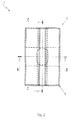
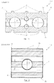
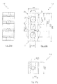
- FIG. 2 shows a plan view of the block 1.1, with cutting curves BB and CC are shown.
- FIGS. 3 and 4 which contain the sectional views BB and CC, in particular, the course of the bushings 3 and 3 'can be seen.
- FIG. 5 shows a block 1.2 of a block system according to the invention in a second embodiment with chamfers on the edges 6, two grooves 4 and two ribs 5, wherein the base body 2 in this embodiment, the bushings 3 and 3 'has.
- FIG. 6 shows a plan view of the module 1.2, wherein the sectional curves DD and EE are drawn.
- FIGS. 7 and 8 which contain the sectional views DD and EE, in particular the course of the bushings 3 and 3 'can be seen.
- FIG. 9 shows a module 1.3 of a modular system according to the invention in a third embodiment with chamfers on the edges 6, three grooves 4 and three ribs 5, which are respectively arranged opposite one another.
- FIG. 10 shows a plan view of the module 1.3, wherein the cutting lines FF and HH are located.
- FIGS. 11 and 12 which include the sectional views FF and HH, in particular, the course of the bushings 3 and 3 'can be seen.
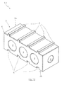
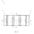
- FIG. 13 shows a block 1.4 of a modular system according to the invention in a fourth embodiment with chamfers on the edges 6, four grooves 4 and four ribs 5, which are respectively arranged opposite one another.
- FIG. 14 shows a plan view of the module 1.4, wherein the cutting lines II and JJ are located.
- FIGS. 15 and 16 which contain the sectional views II and JJ, in particular the course of the bushings 3 and 3 'can be seen.
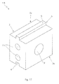
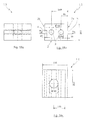
- FIG. 17 shows a module 1.5 of a modular system according to the invention in a fifth embodiment with a groove 4 and a rib 5.
- the edges 6, in contrast to the blocks 1.1 to 1.4 on no chamfers.
- the FIGS. 18a to 18c Some also have dimensions for a specific embodiment of the module 1.5.
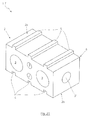
- FIG. 19 shows a module 1.6 of a modular system according to the invention in a sixth embodiment with two grooves 4 and two ribs 5.
- the edges 6 have no chamfers.
- the FIGS. 20a to 20c Some also have dimensions for a specific embodiment of the module 1.6.
- FIG. 21 1 shows a module 1.7 of a modular system according to the invention in a seventh embodiment with three grooves 4 and three ribs 5.
- the edges 6 have no chamfers.
- the FIGS. 22a to 22c Some also have dimensions for a specific embodiment of the module 1.7.
- FIG. 23 shows a module 1.8 of a modular system according to the invention in an eighth embodiment with four grooves 4 and four ribs 5.
- the edges 6 have no chamfers.
- the FIGS. 24a to 24c Some also have dimensions for a specific embodiment of the module 1.8.
- FIG. 25 shows a building block 1.9 of a building block system according to the invention in a ninth embodiment with a groove 4 and a rib 5 and with additional recesses 7 and projections 8 on side surfaces 4a of the groove 4 and 5a of the rib fifth
- the additional lateral projections 8 of the rib 5 can be brought into the corresponding additional lateral recesses 7 of the groove 4 in engagement.
- the module 1.9 also has recesses 9 for insulation material or the like.
- FIG. 26 shows the module 1.9 in a perspective view.
- the building blocks 1.1 - 1.9 can be produced by an injection molding process or by extrusion.
- the surfaces, in particular the side surfaces of the building blocks 1.1 - 1.9 may also be provided with, in particular elongate recesses or grooves in further embodiments, not shown, in order to allow a flush installation of cables, wires and the like.
- At least one side surface of at least one of the building blocks 1.1 - 1.9 may be at least partially roughened.
Landscapes
- Engineering & Computer Science (AREA)
- Architecture (AREA)
- Civil Engineering (AREA)
- Structural Engineering (AREA)
- Physics & Mathematics (AREA)
- Electromagnetism (AREA)
- Floor Finish (AREA)
- Roof Covering Using Slabs Or Stiff Sheets (AREA)
Abstract
Description
- Die Erfindung betrifft ein Bausteinsystem, insbesondere zur Erstellung von Bauwerken.
- Zur Erstellung von Wänden, Garagen, Häusern und anderen Bauwerken kommen bisher häufig Ziegelsteine zum Einsatz, die typischerweise in industrieller Weise aus Ton bzw. Lehm hergestellt sind. Die Ziegelsteine können dabei gebrannt oder getrocknet sein. Die Ziegel erhalten ihre Form meistens durch Stangenpressen und können bei diesem Vorgang auch geschnitten werden. In der Regel haben stangengepresste Ziegel auch sehr glatte Oberflächen. Gemäß dem historischen Vorbild werden rustikale Formbackziegel in der industriellen Fertigung durch ein maschinelles Einwerfen der Tonmasse in Formen gefertigt.
- Bei dem konventionellen Trocknen werden drei verschiedene Typen unterschieden:
- Luftgetrocknete Ziegel mit einer Belastbarkeit von 150 kg/cm2,
- Gebrannte Ziegel mit einer Belastbarkeit von 250 kg/cm2, und
- Hartgebrannte Ziegel mit einer Belastbarkeit von 500 kg/cm2.
- Insbesondere sind auch Unterschiede bei dem jeweiligen Trocknungsverfahren festzustellen. Luftgetrocknete Ziegel, sogenannte Adoben, werden nicht gebrannt, sondern über eine längere Zeit an der Luft getrocknet. Das bedeutet jedoch auch, dass diese bei Aufnahme von Wasser wieder aufweichen können. Somit ist der Einsatz von luftgetrockneten Ziegeln lediglich in niederschlagsarmen bzw. trockenen Regionen der Welt möglich. Derartige luftgetrocknete Ziegelsteine werden auch als Lehmziegel bezeichnet. Gebrannte Ziegel werden im Brennofen gebacken. Im Gegensatz zu luftgetrockneten Ziegeln sind diese Ziegel dauerhaft verfestigt, aber nicht sehr witterungsbeständig, da die gebrannten Ziegel eine hohe Porosität und Wasseraufnahmefähigkeit aufweisen. Solche gebrannten Ziegel werden für Bauzwecke im Innenbereich verwendet oder am fertigen Bauwerk üblicherweise mit Putz abgedeckt. Hartgebrannte Ziegel werden mit höheren Temperaturen gebrannt und sind dadurch härter und dichter als die Ziegel, welche bei niedriger Temperatur gebrannt werden. Dieser Typ von Ziegel findet insbesondere im Außenbereich Verwendung. Dazu zählen unter anderem Vormauerziegel, Klinker und Dachziegel.
- Abhängig von der Brenntemperatur und der Brennatmosphäre kann eine hell- oder dunkelrote Farbtonmischung erzielt werden. Beim Brennvorgang der Ziegel ist ein hoher Energieeinsatz notwendig und die Herstellung ist auch vergleichsweise zeitaufwändig.
- Die entsprechenden Bauwerke werden in der Regel durch ein Aneinander- und ein Übereinandersetzen von einzelnen losen Bausteinen errichtet, wobei typischerweise auch ein Bindemittel zum Verbinden der Bausteine eingesetzt wird. Nach dem Stand der Technik sind verschiedene Bausteingrößen und -geometrien bekannt. Für die Erstellung von Bauwerken können auch größere Einheiten, wie z. B. ganze Wandteile aus Beton, zum Einsatz kommen. Bei der Herstellung, bei dem Transport und beim Verbauen dieser Einheiten sind jedoch geeignete Lastenträger vorzuhalten.
- Die Bausteine aus kleineren und mittelgroßen Ziegelsteinen sowie auch größere Wandteile sind aufwändig in der Herstellung, benötigen ein hohes fachmännisches Wissen und Können bei dem Verbauen und müssen durch Bindemitte zusammengehalten werden. Das Material dieser Bausteine ist spröde und weist insbesondere auch deutliche Nachteile beim Auftreten von Wasser und Feuchtigkeit auf. Zum Schutz der Bausteine und zur Herstellung einer individuell gewünschten Oberflächeneigenschaft der Bauwerke muss eine Beschichtung z. B. durch ein Verputz, eine Tapete oder ein Lack bzw. eine Farbe verwendet werden.
- Der vorliegenden Erfindung liegt die Aufgabe zugrunde, ein Bausteinsystem der eingangs erwähnten Art zu verbessern, wobei insbesondere eine kostengünstige und ressourcenschonende Herstellung sowie eine Langlebigkeit der Bausteine gewährleistet sein soll.
- Diese Aufgabe wird erfindungsgemäß durch ein Bausteinsystem, insbesondere zur Erstellung von Bauwerken, gelöst bei welchem mehrere im wesentlichen aus Kunststoff gebildete, modular zusammensetzbare Bausteine vorhanden sind, welche zur gegenseitigen Fixierung an der Oberseite und/oder an der Unterseite mit wenigstens einem Verbindungselement versehen sind.
- Durch die erfindungsgemäßen Maßnahmen wird ein kostengünstiges, stabiles und langlebiges Bausteinsystem geschaffen. Die Bausteine sind umweltfreundlich herzustellen, einfach und schnell zu verbauen und können individuelle Farb- und Oberflächeneigenschaften aufweisen. Es werden Bausteine mit einer speziellen Geometrie bereitgestellt und dadurch ein schnelles und leichtes Verbauen ermöglicht, wobei auch individuelle Anpassungen, wie z. B. Farbe oder gewünschte Oberflächenstrukturen realisierbar sind. Die genannten Nachteile des Standes der Technik, etwa der hohe Energiebedarf bei der Herstellung, das notwendige hohe Fachwissen bei der Handhabung und die Einschränkung des Einsatzgebiets, treten bei den erfindungsgemäßen Bausteinen nicht auf.
- Das wenigstens eine Verbindungselement eines Bausteins kann als Teil einer formschlüssigen Verbindung in Form einer länglichen Ausnehmung, insbesondere einer Nut oder eines länglichen Vorsprungs, insbesondere einer Rippe ausgebildet und mit einem entsprechend komplementär ausgebildeten Verbindungselement eines weiteren Bausteins in Eingriff bringbar sein. Dadurch können die einzelnen Bausteine in einfacher Weise übereinander gestapelt werden. Die Verbindungselemente können einander gegenüber liegen
- Sehr vorteilhaft ist es, wenn an Seitenflächen des länglichen Vorsprungs eines Bausteins jeweils zusätzliche Vorsprünge vorhanden sind, welche in entsprechende zusätzliche seitliche Ausnehmungen einer länglichen Ausnehmung eines weiteren Bausteins in Eingriff bringbar ist. Sonach kann die Verbindung zwischen den einzelnen Bausteinen noch stabiler ausgeführt werden.
- Das verwendete Rohmaterial der Bausteine kann ein Hochleistungskunststoff, wie z. B. Polyethylenterephthalat (PET), Polyphenylensulfid (PPS) oder Polybutylenterephthalat (PBT) sein. Dadurch werden alle Regularien erfülllt, die auch ein Naturstein erfüllen muss.
- Der Kunststoff der Bausteine kann wenigstens teilweise Recycling-Kunststoff aufweisen.
- Das wenigstens eine Verbindungselement kann einstückig mit den zusammensetzbaren Bausteinen sein.
- Erfindungsgemäß kann ferner vorgesehen sein, dass der Grundkörper wenigstens eines der Bausteine Durchführungen aufweist.
- Die wenigstens eine Kante wenigstens eines der Bausteine kann eine Fase aufweisen, d. h. eine oder mehrere Kanten können abgeschrängte Flächen aufweisen oder abgerundet sein.
- Der Baustein kann in vorteilhafter Weise durch einen Spritzgießvorgang oder durch Extrusion herstellbar sein. Bei dem Spritzgießen kühlen die Kunststoffbausteine nach der Fertigung sofort selbstständig ab und sind nach nur wenigen Sekunden einsetzbar.
- Wenigstens eine Seitenfläche wenigstens eines der Bausteine kann zumindest teilweise aufgeraut sein. Unter Seitenflächen sind hier insbesondere sichtbare Flächen, welche nicht anderen Bausteinen zugewandt sind, zu verstehen. Die Bausteine können in vorteilhafter Weise zumindest teilweise mit aufgerauten Oberflächen versehen sein, um das Aufbringen von mineralischem Putz zu ermöglichen bzw. zu erleichtern.
- Das Verfahren sieht vor, kostengünstige, stabile und langlebige Kunststoffbausteine hervorzubringen. Bei dem neuen Herstellungsverfahren werden die Bausteine nicht aus Lehm oder Ton hergestellt, sondern aus hochfesten und temperaturbeständigen Hochleistungskunststoffen. Bei der Produktion werden diese nicht durch ein Tiefziehen von Kunststoffplatten geformt, sondern ressourcenschonend durch ein konventionelles Spritzgießverfahren hergestellt. In eine Metallform, die sich in der Spritzgießmaschine befindet, wird über Zylinder und Schnecken das vorgetrocknete Kunststoffgranulat direkt in die Form "geschossen" und kann je nach Füll- und Nachdruck seine endgültige Form erhalten. Insbesondere wird bei dieser Herstellung bezogen auf einen Baustein weniger Energie der Umwelt benötigt als beim Brennen von Ziegelsteinen in den modernen Öfen der Industrie. Zudem verwenden die Bausteine entweder den Kunststoff von recycelten Produkten oder sie können nach Verwendung problemlos wieder recycelt werden.
- Ein Kunststoffbaustein für das erfindungsgemäße Bausteinsystem ist in Anspruch 11 angegeben. Durch die Eigenschaften des erfindungsgemäßen Bausteins ist gewährleistet, dass die Herstellung kostengünstig und umweltfreundlich erfolgt und somit einen Beitrag für den Umweltschutz bei gleichzeitiger Langlebigkeit leistet. So ist der Baustein hitzebeständig, UV-stabil, brandsicher, schlagfest, resistent gegenüber Spannungsrissen, biologisch abbaubar, wasserundurchlässig (hydrophob), wärmedämmend und nicht zuletzt formstabil. Diese Bausteine müssen aufgrund ihrer Stabilität und Widerstandskraft auch nicht durch einen Putz vor Umwelteinflüssen geschützt werden. Die Bausteine können somit beispielsweise auch für Keller in Hochwassergebieten zum Einsatz kommen. Die Farbe und/oder die Oberflächengestalt der Kunststoffziegel lassen sich je nach Kundenwunsch individuell gestalten und durch eine Batch-Zugabe (Farbe) produzieren. Die Belastbarkeit dieser Bausteine besteht direkt nach der Herstellung die Anforderung von 500 kg/cm2.
- Die Unteransprüche betreffen vorteilhafte Ausgestaltungen und Weiterbildungen der Erfindung. Im Folgenden sind Ausführungsbeispiele der Erfindung anhand der Zeichnung prinzipmäßig beschrieben.
- Es zeigen:
- Fig. 1
- eine perspektivische Darstellung eines Bausteins eines erfindungsgemäßen Bausteinsystems in einer ersten Ausführungsform mit Fasen an den Kanten, einer Rippe und einer Nut;
- Fig. 2
- eine Draufsicht auf den Baustein aus
Figur 1 ; - Fig. 3
- eine erste Schnittdarstellung des Bausteins aus
Figur 2 ; - Fig. 4
- eine zweite Schnittdarstellung des Bausteins aus
Figur 2 ; - Fig. 5
- eine perspektivische Darstellung eines Bausteins eines erfindungsgemäßen Bausteinsystems in einer zweiten Ausführungsform mit Fasen an den Kanten, zwei Rippen und zwei Nuten;
- Fig. 6
- eine Draufsicht auf den Baustein aus
Figur 5 ; - Fig. 7
- eine erste Schnittdarstellung des Bausteins aus
Figur 6 ; - Fig. 8
- eine zweite Schnittdarstellung des Bausteins aus
Figur 6 ; - Fig. 9
- eine perspektivische Darstellung eines Bausteins eines erfindungsgemäßen Bausteinsystems in einer dritten Ausführungsform mit Fasen an den Kanten, drei Rippen und drei Nuten;
- Fig. 10
- eine Draufsicht auf den Baustein aus
Figur 9 ; - Fig. 11
- eine erste Schnittdarstellung des Bausteins aus
Figur 10 ; - Fig. 12
- eine zweite Schnittdarstellung des Bausteins aus
Figur 10 ; - Fig. 13
- eine perspektivische Darstellung eines Bausteins eines erfindungsgemäßen Bausteinsystems in einer vierten Ausführungsform mit Fasen an den Kanten, vier Rippen und vier Nuten;
- Fig. 14
- eine Draufsicht auf den Baustein aus
Figur 13 ; - Fig. 15
- eine erste Schnittdarstellung des Bausteins aus
Figur 14 ; - Fig. 16
- eine zweite Schnittdarstellung des Bausteins aus
Figur 14 ; - Fig. 17
- eine perspektivische Darstellung eines Bausteins eines erfindungsgemäßen Bausteinsystems in einer fünften Ausführungsform mit einer Rippe und einer Nut;
- Fig. 18a
- bis 18c weitere, teilweise bemaßte Darstellungen des Bausteins aus
Figur 17 ; - Fig. 19
- eine perspektivische Darstellung eines Bausteins eines erfindungsgemäßen Bausteinsystems in einer sechsten Ausführungsform mit zwei Rippen und zwei Nuten;
- Fig. 20a
- bis 20c weitere, teilweise bemaßte Darstellungen des Bausteins aus
Figur 19 ; - Fig. 21
- eine perspektivische Darstellung eines Bausteins eines erfindungsgemäßen Bausteinsystems in einer siebten Ausführungsform mit drei Rippen und drei Nuten;
- Fig. 22
- a bis 22c weitere, teilweise bemaßte Darstellungen des Bausteins aus
Figur 21 ; - Fig. 23
- eine perspektivische Darstellung eines Bausteins eines erfindungsgemäßen Bausteinsystems in einer achten Ausführungsform mit vier Rippen und vier Nuten;
- Fig. 24a
- bis 24c weitere, teilweise bemaßte Darstellungen des Bausteins aus
Figur 23 ; - Fig. 25
- eine Seitenansicht eines Bausteins eines erfindungsgemäßen Bausteinsystems in einer neunten Ausführungsform mit einer Rippe und einer Nut und mit zusätzlichen Vorsprüngen und Ausnehmungen; und
- Fig. 26
- eine perspektivische Darstellung des Bausteins aus
Figur 25 . -
Figur 1 zeigt einen Baustein 1.1 eines erfindungsgemäßen Bausteinsystems zur Erstellung von Bauwerken (nicht dargestellt) in einer ersten Ausführungsform. Das erfindungsgemäße Bausteinsystem wird durch mehrere im wesentlichen bzw. im vorliegenden Ausführungsbeispiel vollständig aus Kunststoff, insbesondere Hochleistungskunststoff, vorzugsweise Polyethylenterephthalat (PET) gebildete, modular zusammensetzbare Bausteine 1.1 gebildet, welche zur gegenseitigen Fixierung an einer Oberseite 2a und an einer Unterseite 2b eines Grundkörpers 2 mit einem Verbindungselement 4, 5 versehen sind. Der Grundkörper 2 kann, wie hier dargestellt, quaderförmig sein und mit Durchführungen 3 bzw. 3' versehen sein. Die Durchführungen 3 bzw. 3' können dabei im Wesentlichen zylindrisch sein oder auch andere Querschnittsgeometrien besitzen. Auch die Anzahl und die lateralen Abmessungen der Durchführungen 3 bzw. 3' werden lediglich durch die äußere Form des Grundkörpers 2 begrenzt. Durch die Durchführungen 3 bzw. 3' können unter anderem Kabel und Rohrleitungen gelegt werden. - Die Verbindungselemente 4, 5 des Bausteins 1.1 sind als Teil einer formschlüssigen Verbindung in Form einer als Nut 4 ausgeführten länglichen Ausnehmung oder eines als Rippe 5 ausgeführten länglichen Vorsprungs ausgebildet und mit entsprechend komplementär ausgebildeten Verbindungselementen 4, 5 eines weiteren Bausteins 1.1 in Eingriff bringbar. Die Nut 4 befindet sich in dem gezeigten Beispiel an der Unterseite 2b des Grundkörpers 2 und auf der gegenüberliegenden Seite, der Oberseite des Grundkörpers 2, ist die Rippe 5 angeordnet. Die Nut 4 und die Rippe 5 sind hier beide quaderförmig gestaltet, wobei prinzipiell auch andere Geometrien möglich sind. Die Abmessungen der Nut 4 und der Rippe 5 sind derart gewählt, dass der gezeigte Baustein 1.1 mit weiteren hier nicht dargestellten Bausteinen 1.1 stapelbar ist, wobei die Rippe 5 des einen Bausteins 1.1 in die Nut 4 des anderen Bausteins 1.1 greift. Die Verbindungselemente 4, 5 sind im vorliegenden Ausführungsbeispiel einstückig mit den zusammensetzbaren Bausteinen 1.1 ausgebildet.
- Wie aus
Figur 1 weiter ersichtlich sind Kanten 6 des Bausteins 1.1 mit Fasen versehen. - In anderen Ausführungsbeispielen können auch weitere Kunststoffe, wie etwa Polyphenylensulfid (PPS) oder Polybutylenterephthalat (PBT) als Rohmaterial verwendet werden. Der Kunststoff kann wenigstens teilweise Recycling-Kunststoff aufweisen.
- Die
Figur 2 zeigt eine Draufsicht des Bausteins 1.1, wobei Schnittverläufe B-B und C-C eingezeichnet sind. - Aus den
Figuren 3 und 4 , welche die Schnittdarstellungen B-B bzw. C-C enthalten, ist insbesondere der Verlauf der Durchführungen 3 und 3' zu erkennen. -
Figur 5 zeigt einen Baustein 1.2 eines erfindungsgemäßen Bausteinsystems in einer zweiten Ausführungsform mit Fasen an den Kanten 6, zwei Nuten 4 und zwei Rippen 5, wobei der Grundkörper 2 bei diesem Ausführungsbeispiel die Durchführungen 3 und 3' aufweist. - Die
Figur 6 zeigt eine Draufsicht des Bausteins 1.2, wobei die Schnittverläufe D-D und E-E eingezeichnet sind. - Aus den
Figuren 7 und 8 , welche die Schnittdarstellungen D-D bzw. E-E enthalten, ist insbesondere der Verlauf der Durchführungen 3 und 3' ersichtlich. -
Figur 9 zeigt einen Baustein 1.3 eines erfindungsgemäßen Bausteinsystems in einer dritten Ausführungsform mit Fasen an den Kanten 6, drei Nuten 4 und drei Rippen 5, die jeweils gegenüberliegend angeordnet sind. -
Figur 10 zeigt eine Draufsicht des Bausteins 1.3, wobei die Schnittverläufe F-F und H-H eingezeichnet sind. - In den
Figuren 11 und 12 , welche die Schnittdarstellungen F-F bzw. H-H enthalten, ist insbesondere der Verlauf der Durchführungen 3 und 3' zu erkennen. -
Figur 13 zeigt einen Baustein 1.4 eines erfindungsgemäßen Bausteinsystems in einer vierten Ausführungsform mit Fasen an den Kanten 6, vier Nuten 4 und vier Rippen 5, die jeweils gegenüberliegend angeordnet sind. -
Figur 14 zeigt eine Draufsicht des Bausteins 1.4, wobei die Schnittverläufe I-I und J-J eingezeichnet sind. - Aus den
Figuren 15 und 16 , welche die Schnittdarstellungen I-I bzw. J-J enthalten, ist insbesondere der Verlauf der Durchführungen 3 und 3' ersichtlich. -
Figur 17 zeigt einen Baustein 1.5 eines erfindungsgemäßen Bausteinsystems in einer fünften Ausführungsform mit einer Nut 4 und einer Rippe 5. Die Kanten 6 weisen im Gegensatz zu den Bausteinen 1.1 bis 1.4 keine Fasen auf. DieFiguren 18a bis 18c weisen teilweise auch Maßangaben für ein konkretes Ausführungsbeispiel des Bausteins 1.5 auf. -
Figur 19 zeigt einen Baustein 1.6 eines erfindungsgemäßen Bausteinsystems in einer sechsten Ausführungsform mit zwei Nuten 4 und zwei Rippen 5. Die Kanten 6 weisen keine Fasen auf. DieFiguren 20a bis 20c weisen teilweise auch Maßangaben für ein konkretes Ausführungsbeispiel des Bausteins 1.6 auf. -
Figur 21 zeigt einen Baustein 1.7 eines erfindungsgemäßen Bausteinsystems in einer siebten Ausführungsform mit drei Nuten 4 und drei Rippen 5. Die Kanten 6 weisen keine Fasen auf. DieFiguren 22a bis 22c weisen teilweise auch Maßangaben für ein konkretes Ausführungsbeispiel des Bausteins 1.7 auf. -
Figur 23 zeigt einen Baustein 1.8 eines erfindungsgemäßen Bausteinsystems in einer achten Ausführungsform mit vier Nuten 4 und vier Rippen 5. Die Kanten 6 weisen keine Fasen auf. DieFiguren 24a bis 24c weisen teilweise auch Maßangaben für ein konkretes Ausführungsbeispiel des Bausteins 1.8 auf. -
Figur 25 zeigt einen Baustein 1.9 eines erfindungsgemäßen Bausteinsystems in einer neunten Ausführungsform mit einer Nut 4 und einer Rippe 5 und mit zusätzlichen Ausnehmungen 7 und Vorsprüngen 8 an Seitenflächen 4a der Nut 4 bzw. 5a der Rippe 5. - Die zusätzlichen seitlichen Vorsprünge 8 der Rippe 5 sind in die entsprechenden zusätzlichen seitlichen Ausnehmungen 7 der Nut 4 in Eingriff bringbar.
- Der Baustein 1.9 weist darüber hinaus Ausnehmungen 9 für Dämmmaterial oder dergleichen auf.
-
Figur 26 zeigt den Baustein 1.9 in einer perspektivischen Darstellung. - In weiteren nicht dargestellten Ausführungsbeispielen können selbstverständlich auch andere Anzahlen von Rippen 5 und Nuten 4 - auch in unterschiedlich Anzahlen auf der Oberseite 2a und der Unterseite 2b oder nicht gegenüberliegend vorgesehen sein.
- Die Maße, d. h. Länge, Breite und Höhe der Bausteine 1.1 - 1.9 sind selbstverständlich entsprechend frei wählbar.
- Die Bausteine 1.1 - 1.9 können durch einen Spritzgießvorgang oder durch Extrusion herstellbar sein.
- Die Flächen, insbesondere die Seitenflächen der Bausteine 1.1 - 1.9 können in weiteren nicht dargestellten Ausführungsbeispielen auch mit, insbesondere länglichen Ausnehmungen bzw. Nuten versehen sein, um eine Unterputzverlegung von Kabeln, Leitungen und dergleichen zu ermöglichen.
- Wenigstens eine Seitenfläche wenigstens eines der Bausteine 1.1 - 1.9 kann zumindest teilweise aufgeraut sein.
-
- 1.1 - 1.9
- Baustein
- 2
- Grundkörper
- 2a
- Oberseite
- 2b
- Unterseite
- 3, 3'
- Durchführungen
- 4
- Nut
- 4a
- Seitenfläche
- 5
- Rippe
- 5a
- Seitenfläche
- 6
- Kante
- 7
- Ausnehmung
- 8
- Vorsprung
- 9
- Ausnehmung
Claims (11)
- Bausteinsystem, insbesondere zur Erstellung von Bauwerken, gekennzeichnet durch
mehrere im wesentlichen aus Kunststoff gebildete, modular zusammensetzbare Bausteine (1.1 bis 1.9), welche zur gegenseitigen Fixierung an der Oberseite (2a) und/oder an der Unterseite (2b) mit wenigstens einem Verbindungselement (4,5) versehen sind. - Bausteinsystem nach Anspruch 1,
dadurch gekennzeichnet, dass das wenigstens eine Verbindungselement (4,5) eines Bausteins (1.1 bis 1.9) als Teil einer formschlüssigen Verbindung in Form einer länglichen Ausnehmung (4) oder eines länglichen Vorsprungs (5) ausgebildet und mit einem entsprechend komplementär ausgebildeten Verbindungselement (4,5) eines weiteren Bausteins (1.1-1.9) in Eingriff bringbar ist. - Bausteinsystem nach Anspruch 2,
dadurch gekennzeichnet, dass an Seitenflächen (4a,5a) des länglichen Vorsprungs (5) eines Bausteins (1.9) jeweils zusätzliche Vorsprünge (8) vorhanden sind, welche in entsprechende zusätzliche seitliche Ausnehmungen (7) einer länglichen Ausnehmung (4) eines weiteren Bausteins (1.9) in Eingriff bringbar ist. - Bausteinsystem nach Anspruch 1, 2 oder 3,
dadurch gekennzeichnet, dass der Kunststoff ein Hochleistungskunststoff, insbesondere Polyethylenterephthalat (PET), Polyphenylensulfid (PPS) oder Polybutylenterephthalat (PBT) ist. - Bausteinsystem nach einem der Ansprüche 1 bis 4,
dadurch gekennzeichnet, dass der Kunststoff wenigstens teilweise Recycling-Kunststoff aufweist. - Bausteinsystem nach einem der Ansprüche 1 bis 5,
dadurch gekennzeichnet, dass das wenigstens eine Verbindungselement (4,5) einstückig mit den zusammensetzbaren Bausteinen (1.1-1.9) ist. - Bausteinsystem nach einem der Ansprüche 1 bis 6,
dadurch gekennzeichnet, dass der Grundkörper (2) wenigstens eines der Bausteine (1.1-1.9) Durchführungen (3,3') aufweist. - Bausteinsystem nach einem der Ansprüche 1 bis 7,
dadurch gekennzeichnet, dass wenigstens eine Kante (6) wenigstens eines der Bausteine (1.1-1.4) eine Fase aufweist. - Bausteinsystem nach einem der Ansprüche 1 bis 8,
dadurch gekennzeichnet, dass wenigstens einer der Bausteine (1.1-1.9) durch einen Spritzgießvorgang oder durch Extrusion herstellbar ist. - Bausteinsystem nach einem der Ansprüche 1 bis 9,
dadurch gekennzeichnet, dass wenigstens eine Seitenfläche wenigstens eines der Bausteine (1.1-1.9) zumindest teilweise aufgeraut ist. - Kunststoffbaustein (1.1-1.9) eines Bausteinsystems nach einem der Ansprüche 1 bis 10.
Applications Claiming Priority (2)
| Application Number | Priority Date | Filing Date | Title |
|---|---|---|---|
| DE102010027600 | 2010-07-20 | ||
| DE201110005178 DE102011005178A1 (de) | 2010-07-20 | 2011-03-07 | Bausteinsystem, insbesondere zur Erstellung von Bauwerken |
Publications (3)
| Publication Number | Publication Date |
|---|---|
| EP2410102A2 true EP2410102A2 (de) | 2012-01-25 |
| EP2410102A3 EP2410102A3 (de) | 2012-11-28 |
| EP2410102B1 EP2410102B1 (de) | 2016-07-20 |
Family
ID=44278956
Family Applications (1)
| Application Number | Title | Priority Date | Filing Date |
|---|---|---|---|
| EP11167200.2A Not-in-force EP2410102B1 (de) | 2010-07-20 | 2011-05-24 | Bausteinsystem, insbesondere zur Erstellung von Bauwerken |
Country Status (2)
| Country | Link |
|---|---|
| EP (1) | EP2410102B1 (de) |
| DE (1) | DE102011005178A1 (de) |
Cited By (3)
| Publication number | Priority date | Publication date | Assignee | Title |
|---|---|---|---|---|
| EP3168382A1 (de) * | 2015-11-12 | 2017-05-17 | RC Beton A/S | Bausteinsystem |
| WO2018157134A1 (en) * | 2017-02-27 | 2018-08-30 | Ball Corporation | Pallet-less brick |
| FR3120883A1 (fr) * | 2021-03-17 | 2022-09-23 | Eloge Franck David Koubemba | Parpaing semi-emboitee realise manuellement |
Families Citing this family (1)
| Publication number | Priority date | Publication date | Assignee | Title |
|---|---|---|---|---|
| MX2024003430A (es) * | 2024-03-19 | 2024-04-08 | Alejandro Jose Biehl Flores | Elementos constructivos rectangulares y cuadrangulares de ensamble. |
Family Cites Families (6)
| Publication number | Priority date | Publication date | Assignee | Title |
|---|---|---|---|---|
| GR61482B (en) * | 1978-09-15 | 1978-11-18 | A Sagionis | Manufacture of building bricks with outside coating and inside line |
| GB2272229B (en) * | 1992-04-24 | 1996-06-19 | Sean Lawless | Insulation of walls |
| DE4323049A1 (de) * | 1993-07-11 | 1995-03-30 | Philipp Stephanie | Bauteile für den Wohnungs-, Hallenbau usw., Herstellungsverfahren für Baustoffe use. |
| GB0425630D0 (en) * | 2004-11-22 | 2004-12-22 | Whitaker Jace | Building block |
| US20060156656A1 (en) * | 2005-01-19 | 2006-07-20 | Robinson Gerald M | Aggregate log and method of building construction |
| ES2298029B1 (es) * | 2006-04-24 | 2009-06-29 | Pablo Campos Lopez | Elemento constructivo. |
-
2011
- 2011-03-07 DE DE201110005178 patent/DE102011005178A1/de not_active Withdrawn
- 2011-05-24 EP EP11167200.2A patent/EP2410102B1/de not_active Not-in-force
Non-Patent Citations (1)
| Title |
|---|
| None |
Cited By (4)
| Publication number | Priority date | Publication date | Assignee | Title |
|---|---|---|---|---|
| EP3168382A1 (de) * | 2015-11-12 | 2017-05-17 | RC Beton A/S | Bausteinsystem |
| WO2018157134A1 (en) * | 2017-02-27 | 2018-08-30 | Ball Corporation | Pallet-less brick |
| US10486873B2 (en) | 2017-02-27 | 2019-11-26 | Ball Corporation | Pallet-less brick |
| FR3120883A1 (fr) * | 2021-03-17 | 2022-09-23 | Eloge Franck David Koubemba | Parpaing semi-emboitee realise manuellement |
Also Published As
| Publication number | Publication date |
|---|---|
| DE102011005178A1 (de) | 2012-01-26 |
| EP2410102A3 (de) | 2012-11-28 |
| EP2410102B1 (de) | 2016-07-20 |
Similar Documents
| Publication | Publication Date | Title |
|---|---|---|
| DE3610030C1 (de) | Bauelement fuer Hochbauwerke | |
| DE102007061451A1 (de) | Hochlochziegel | |
| EP2410102B1 (de) | Bausteinsystem, insbesondere zur Erstellung von Bauwerken | |
| DE202018100177U1 (de) | Schalungsvorrichtung zur Herstellung von Betonstützen, insbesondere zur Herstellung von Teile einer Mauer bildenden vertikalen Betonstützen | |
| DE102008039919A1 (de) | Vorgefertigte Ziegeleinheit | |
| DE202011110256U1 (de) | Baustein, insbesondere zur Erstellung von Bauwerken | |
| DE69321222T2 (de) | Verstärktes Produkt, bestehend aus Naturstein- oder Konglomerat-Platte | |
| DE202011110213U1 (de) | Vorrichtung zum Herstellen eines Formkörpers mit Lichtleitern sowie Formkörper aus einer härtbaren oder aushärtbaren gießfähigen Masse | |
| DE102017011331A1 (de) | Formstein zur Errichtung von Mauern und Gebäuden | |
| EP3569788B1 (de) | Segment für ein bauwerk, verfahren zu dessen herstellung, ecksegment für ein bauwerk, verfahren zu dessen herstellung, bauwerk und verfahren zu dessen herstellung | |
| EP3768908B1 (de) | Wand oder gebäudehülle | |
| EP2692960A1 (de) | Bauelement mit lichtdurchlässigen Eigenschaften | |
| DE2939768A1 (de) | Bauelement, insbesondere fuer wandkonstruktionen, und ziegel als vorfabrikat zu dessen herstellung | |
| EP0748905B1 (de) | Bauelement | |
| DE102016003219A1 (de) | Baustein zur Bildung von Bauwerken aus Kunststoff mit Fixirungselementen an Ober-/Unterseite. Zur Stabilität trägt die hochfeste Wabenstruktur im Inneren des Bausteinkörpers, sowie die eingeschlossenen Wabenkammern zur Dämmung bei. Aufgeraute Flächen ermöglichen das anbringen von weiteren Stoffen (z.B. Putz). | |
| EP0470945B1 (de) | Schornsteinbauteil, Mehrfach Schornsteinsystem sowie Verfahren zur Herstellung eines Schornsteinbauteiles | |
| EP3456896A1 (de) | Schalungsvorrichtung zur herstellung von betonstützen, insbesondere zur herstellung von teile einer mauer bildenden vertikalen betonstützen | |
| DE102008017720A1 (de) | Isolierschalstein | |
| DE3025135A1 (de) | Verbundbauelement aus beton, insbesondere deckenelement, verfahren zu seiner herstellung und verwendung im bauwesen | |
| DE4443185C2 (de) | Fliese sowie Verfahren zum Herstellen von Fliesen | |
| AT500732A2 (de) | Formsteinsatz zum erstellen von flächenbelägen aus betonstein | |
| DE102018101708A1 (de) | Mauerstein sowie Verfahren zu dessen Herstellung | |
| EP4382688A1 (de) | Kammerstein, mauerwerk und verfahren zum herstellen eines kammersteins | |
| DE102023107633A1 (de) | Baukastensystem zur Herstellung von Bauwerken | |
| DE4200815A1 (de) | Formstein |
Legal Events
| Date | Code | Title | Description |
|---|---|---|---|
| AK | Designated contracting states |
Kind code of ref document: A2 Designated state(s): AL AT BE BG CH CY CZ DE DK EE ES FI FR GB GR HR HU IE IS IT LI LT LU LV MC MK MT NL NO PL PT RO RS SE SI SK SM TR |
|
| AX | Request for extension of the european patent |
Extension state: BA ME |
|
| PUAI | Public reference made under article 153(3) epc to a published international application that has entered the european phase |
Free format text: ORIGINAL CODE: 0009012 |
|
| PUAL | Search report despatched |
Free format text: ORIGINAL CODE: 0009013 |
|
| AK | Designated contracting states |
Kind code of ref document: A3 Designated state(s): AL AT BE BG CH CY CZ DE DK EE ES FI FR GB GR HR HU IE IS IT LI LT LU LV MC MK MT NL NO PL PT RO RS SE SI SK SM TR |
|
| AX | Request for extension of the european patent |
Extension state: BA ME |
|
| RIC1 | Information provided on ipc code assigned before grant |
Ipc: E04B 2/18 20060101ALI20121025BHEP Ipc: E04C 1/00 20060101AFI20121025BHEP |
|
| 17P | Request for examination filed |
Effective date: 20130528 |
|
| RBV | Designated contracting states (corrected) |
Designated state(s): AL AT BE BG CH CY CZ DE DK EE ES FI FR GB GR HR HU IE IS IT LI LT LU LV MC MK MT NL NO PL PT RO RS SE SI SK SM TR |
|
| 17Q | First examination report despatched |
Effective date: 20140826 |
|
| GRAP | Despatch of communication of intention to grant a patent |
Free format text: ORIGINAL CODE: EPIDOSNIGR1 |
|
| INTG | Intention to grant announced |
Effective date: 20160308 |
|
| GRAS | Grant fee paid |
Free format text: ORIGINAL CODE: EPIDOSNIGR3 |
|
| GRAA | (expected) grant |
Free format text: ORIGINAL CODE: 0009210 |
|
| AK | Designated contracting states |
Kind code of ref document: B1 Designated state(s): AL AT BE BG CH CY CZ DE DK EE ES FI FR GB GR HR HU IE IS IT LI LT LU LV MC MK MT NL NO PL PT RO RS SE SI SK SM TR |
|
| REG | Reference to a national code |
Ref country code: GB Ref legal event code: FG4D Free format text: NOT ENGLISH |
|
| REG | Reference to a national code |
Ref country code: CH Ref legal event code: EP |
|
| REG | Reference to a national code |
Ref country code: IE Ref legal event code: FG4D Free format text: LANGUAGE OF EP DOCUMENT: GERMAN |
|
| REG | Reference to a national code |
Ref country code: AT Ref legal event code: REF Ref document number: 814233 Country of ref document: AT Kind code of ref document: T Effective date: 20160815 |
|
| REG | Reference to a national code |
Ref country code: DE Ref legal event code: R096 Ref document number: 502011010189 Country of ref document: DE |
|
| REG | Reference to a national code |
Ref country code: LT Ref legal event code: MG4D |
|
| REG | Reference to a national code |
Ref country code: NL Ref legal event code: MP Effective date: 20160720 |
|
| PG25 | Lapsed in a contracting state [announced via postgrant information from national office to epo] |
Ref country code: RS Free format text: LAPSE BECAUSE OF FAILURE TO SUBMIT A TRANSLATION OF THE DESCRIPTION OR TO PAY THE FEE WITHIN THE PRESCRIBED TIME-LIMIT Effective date: 20160720 Ref country code: NL Free format text: LAPSE BECAUSE OF FAILURE TO SUBMIT A TRANSLATION OF THE DESCRIPTION OR TO PAY THE FEE WITHIN THE PRESCRIBED TIME-LIMIT Effective date: 20160720 Ref country code: NO Free format text: LAPSE BECAUSE OF FAILURE TO SUBMIT A TRANSLATION OF THE DESCRIPTION OR TO PAY THE FEE WITHIN THE PRESCRIBED TIME-LIMIT Effective date: 20161020 Ref country code: HR Free format text: LAPSE BECAUSE OF FAILURE TO SUBMIT A TRANSLATION OF THE DESCRIPTION OR TO PAY THE FEE WITHIN THE PRESCRIBED TIME-LIMIT Effective date: 20160720 Ref country code: LT Free format text: LAPSE BECAUSE OF FAILURE TO SUBMIT A TRANSLATION OF THE DESCRIPTION OR TO PAY THE FEE WITHIN THE PRESCRIBED TIME-LIMIT Effective date: 20160720 Ref country code: IT Free format text: LAPSE BECAUSE OF FAILURE TO SUBMIT A TRANSLATION OF THE DESCRIPTION OR TO PAY THE FEE WITHIN THE PRESCRIBED TIME-LIMIT Effective date: 20160720 Ref country code: FI Free format text: LAPSE BECAUSE OF FAILURE TO SUBMIT A TRANSLATION OF THE DESCRIPTION OR TO PAY THE FEE WITHIN THE PRESCRIBED TIME-LIMIT Effective date: 20160720 Ref country code: IS Free format text: LAPSE BECAUSE OF FAILURE TO SUBMIT A TRANSLATION OF THE DESCRIPTION OR TO PAY THE FEE WITHIN THE PRESCRIBED TIME-LIMIT Effective date: 20161120 |
|
| PG25 | Lapsed in a contracting state [announced via postgrant information from national office to epo] |
Ref country code: GR Free format text: LAPSE BECAUSE OF FAILURE TO SUBMIT A TRANSLATION OF THE DESCRIPTION OR TO PAY THE FEE WITHIN THE PRESCRIBED TIME-LIMIT Effective date: 20161021 Ref country code: SE Free format text: LAPSE BECAUSE OF FAILURE TO SUBMIT A TRANSLATION OF THE DESCRIPTION OR TO PAY THE FEE WITHIN THE PRESCRIBED TIME-LIMIT Effective date: 20160720 Ref country code: PT Free format text: LAPSE BECAUSE OF FAILURE TO SUBMIT A TRANSLATION OF THE DESCRIPTION OR TO PAY THE FEE WITHIN THE PRESCRIBED TIME-LIMIT Effective date: 20161121 Ref country code: LV Free format text: LAPSE BECAUSE OF FAILURE TO SUBMIT A TRANSLATION OF THE DESCRIPTION OR TO PAY THE FEE WITHIN THE PRESCRIBED TIME-LIMIT Effective date: 20160720 Ref country code: ES Free format text: LAPSE BECAUSE OF FAILURE TO SUBMIT A TRANSLATION OF THE DESCRIPTION OR TO PAY THE FEE WITHIN THE PRESCRIBED TIME-LIMIT Effective date: 20160720 Ref country code: PL Free format text: LAPSE BECAUSE OF FAILURE TO SUBMIT A TRANSLATION OF THE DESCRIPTION OR TO PAY THE FEE WITHIN THE PRESCRIBED TIME-LIMIT Effective date: 20160720 |
|
| REG | Reference to a national code |
Ref country code: DE Ref legal event code: R097 Ref document number: 502011010189 Country of ref document: DE |
|
| PG25 | Lapsed in a contracting state [announced via postgrant information from national office to epo] |
Ref country code: RO Free format text: LAPSE BECAUSE OF FAILURE TO SUBMIT A TRANSLATION OF THE DESCRIPTION OR TO PAY THE FEE WITHIN THE PRESCRIBED TIME-LIMIT Effective date: 20160720 Ref country code: EE Free format text: LAPSE BECAUSE OF FAILURE TO SUBMIT A TRANSLATION OF THE DESCRIPTION OR TO PAY THE FEE WITHIN THE PRESCRIBED TIME-LIMIT Effective date: 20160720 |
|
| PLBE | No opposition filed within time limit |
Free format text: ORIGINAL CODE: 0009261 |
|
| STAA | Information on the status of an ep patent application or granted ep patent |
Free format text: STATUS: NO OPPOSITION FILED WITHIN TIME LIMIT |
|
| PG25 | Lapsed in a contracting state [announced via postgrant information from national office to epo] |
Ref country code: SK Free format text: LAPSE BECAUSE OF FAILURE TO SUBMIT A TRANSLATION OF THE DESCRIPTION OR TO PAY THE FEE WITHIN THE PRESCRIBED TIME-LIMIT Effective date: 20160720 Ref country code: SM Free format text: LAPSE BECAUSE OF FAILURE TO SUBMIT A TRANSLATION OF THE DESCRIPTION OR TO PAY THE FEE WITHIN THE PRESCRIBED TIME-LIMIT Effective date: 20160720 Ref country code: DK Free format text: LAPSE BECAUSE OF FAILURE TO SUBMIT A TRANSLATION OF THE DESCRIPTION OR TO PAY THE FEE WITHIN THE PRESCRIBED TIME-LIMIT Effective date: 20160720 Ref country code: CZ Free format text: LAPSE BECAUSE OF FAILURE TO SUBMIT A TRANSLATION OF THE DESCRIPTION OR TO PAY THE FEE WITHIN THE PRESCRIBED TIME-LIMIT Effective date: 20160720 Ref country code: BG Free format text: LAPSE BECAUSE OF FAILURE TO SUBMIT A TRANSLATION OF THE DESCRIPTION OR TO PAY THE FEE WITHIN THE PRESCRIBED TIME-LIMIT Effective date: 20161020 |
|
| 26N | No opposition filed |
Effective date: 20170421 |
|
| PG25 | Lapsed in a contracting state [announced via postgrant information from national office to epo] |
Ref country code: LU Free format text: LAPSE BECAUSE OF NON-PAYMENT OF DUE FEES Effective date: 20170531 Ref country code: SI Free format text: LAPSE BECAUSE OF FAILURE TO SUBMIT A TRANSLATION OF THE DESCRIPTION OR TO PAY THE FEE WITHIN THE PRESCRIBED TIME-LIMIT Effective date: 20160720 |
|
| REG | Reference to a national code |
Ref country code: CH Ref legal event code: PL |
|
| GBPC | Gb: european patent ceased through non-payment of renewal fee |
Effective date: 20170524 |
|
| PG25 | Lapsed in a contracting state [announced via postgrant information from national office to epo] |
Ref country code: MC Free format text: LAPSE BECAUSE OF FAILURE TO SUBMIT A TRANSLATION OF THE DESCRIPTION OR TO PAY THE FEE WITHIN THE PRESCRIBED TIME-LIMIT Effective date: 20160720 |
|
| REG | Reference to a national code |
Ref country code: IE Ref legal event code: MM4A |
|
| PG25 | Lapsed in a contracting state [announced via postgrant information from national office to epo] |
Ref country code: CH Free format text: LAPSE BECAUSE OF NON-PAYMENT OF DUE FEES Effective date: 20170531 Ref country code: LI Free format text: LAPSE BECAUSE OF NON-PAYMENT OF DUE FEES Effective date: 20170531 |
|
| REG | Reference to a national code |
Ref country code: FR Ref legal event code: ST Effective date: 20180131 |
|
| PG25 | Lapsed in a contracting state [announced via postgrant information from national office to epo] |
Ref country code: LU Free format text: LAPSE BECAUSE OF NON-PAYMENT OF DUE FEES Effective date: 20170524 |
|
| REG | Reference to a national code |
Ref country code: BE Ref legal event code: MM Effective date: 20170531 |
|
| PG25 | Lapsed in a contracting state [announced via postgrant information from national office to epo] |
Ref country code: GB Free format text: LAPSE BECAUSE OF NON-PAYMENT OF DUE FEES Effective date: 20170524 Ref country code: IE Free format text: LAPSE BECAUSE OF NON-PAYMENT OF DUE FEES Effective date: 20170524 |
|
| PG25 | Lapsed in a contracting state [announced via postgrant information from national office to epo] |
Ref country code: FR Free format text: LAPSE BECAUSE OF NON-PAYMENT OF DUE FEES Effective date: 20170531 |
|
| REG | Reference to a national code |
Ref country code: AT Ref legal event code: MM01 Ref document number: 814233 Country of ref document: AT Kind code of ref document: T Effective date: 20170524 |
|
| PGFP | Annual fee paid to national office [announced via postgrant information from national office to epo] |
Ref country code: DE Payment date: 20180525 Year of fee payment: 8 |
|
| PG25 | Lapsed in a contracting state [announced via postgrant information from national office to epo] |
Ref country code: AT Free format text: LAPSE BECAUSE OF NON-PAYMENT OF DUE FEES Effective date: 20170524 Ref country code: BE Free format text: LAPSE BECAUSE OF NON-PAYMENT OF DUE FEES Effective date: 20170531 |
|
| PG25 | Lapsed in a contracting state [announced via postgrant information from national office to epo] |
Ref country code: MT Free format text: LAPSE BECAUSE OF FAILURE TO SUBMIT A TRANSLATION OF THE DESCRIPTION OR TO PAY THE FEE WITHIN THE PRESCRIBED TIME-LIMIT Effective date: 20160720 |
|
| PG25 | Lapsed in a contracting state [announced via postgrant information from national office to epo] |
Ref country code: AL Free format text: LAPSE BECAUSE OF FAILURE TO SUBMIT A TRANSLATION OF THE DESCRIPTION OR TO PAY THE FEE WITHIN THE PRESCRIBED TIME-LIMIT Effective date: 20160720 |
|
| PG25 | Lapsed in a contracting state [announced via postgrant information from national office to epo] |
Ref country code: HU Free format text: LAPSE BECAUSE OF FAILURE TO SUBMIT A TRANSLATION OF THE DESCRIPTION OR TO PAY THE FEE WITHIN THE PRESCRIBED TIME-LIMIT; INVALID AB INITIO Effective date: 20110524 |
|
| PG25 | Lapsed in a contracting state [announced via postgrant information from national office to epo] |
Ref country code: CY Free format text: LAPSE BECAUSE OF NON-PAYMENT OF DUE FEES Effective date: 20160720 |
|
| PG25 | Lapsed in a contracting state [announced via postgrant information from national office to epo] |
Ref country code: MK Free format text: LAPSE BECAUSE OF FAILURE TO SUBMIT A TRANSLATION OF THE DESCRIPTION OR TO PAY THE FEE WITHIN THE PRESCRIBED TIME-LIMIT Effective date: 20160720 |
|
| REG | Reference to a national code |
Ref country code: DE Ref legal event code: R119 Ref document number: 502011010189 Country of ref document: DE |
|
| PG25 | Lapsed in a contracting state [announced via postgrant information from national office to epo] |
Ref country code: TR Free format text: LAPSE BECAUSE OF FAILURE TO SUBMIT A TRANSLATION OF THE DESCRIPTION OR TO PAY THE FEE WITHIN THE PRESCRIBED TIME-LIMIT Effective date: 20160720 |
|
| PG25 | Lapsed in a contracting state [announced via postgrant information from national office to epo] |
Ref country code: DE Free format text: LAPSE BECAUSE OF NON-PAYMENT OF DUE FEES Effective date: 20191203 |