EP2409626A1 - Staubsauger, insbesondere einen Bodenstaubsauger, mit mindestens einer Aufnahme für Saugzubehör - Google Patents
Staubsauger, insbesondere einen Bodenstaubsauger, mit mindestens einer Aufnahme für Saugzubehör Download PDFInfo
- Publication number
- EP2409626A1 EP2409626A1 EP10401117A EP10401117A EP2409626A1 EP 2409626 A1 EP2409626 A1 EP 2409626A1 EP 10401117 A EP10401117 A EP 10401117A EP 10401117 A EP10401117 A EP 10401117A EP 2409626 A1 EP2409626 A1 EP 2409626A1
- Authority
- EP
- European Patent Office
- Prior art keywords
- vacuum cleaner
- functional module
- suction
- receptacle
- hooks
- Prior art date
- Legal status (The legal status is an assumption and is not a legal conclusion. Google has not performed a legal analysis and makes no representation as to the accuracy of the status listed.)
- Granted
Links
Images



Classifications
-
- A—HUMAN NECESSITIES
- A47—FURNITURE; DOMESTIC ARTICLES OR APPLIANCES; COFFEE MILLS; SPICE MILLS; SUCTION CLEANERS IN GENERAL
- A47L—DOMESTIC WASHING OR CLEANING; SUCTION CLEANERS IN GENERAL
- A47L9/00—Details or accessories of suction cleaners, e.g. mechanical means for controlling the suction or for effecting pulsating action; Storing devices specially adapted to suction cleaners or parts thereof; Carrying-vehicles specially adapted for suction cleaners
- A47L9/0009—Storing devices ; Supports, stands or holders
-
- A—HUMAN NECESSITIES
- A47—FURNITURE; DOMESTIC ARTICLES OR APPLIANCES; COFFEE MILLS; SPICE MILLS; SUCTION CLEANERS IN GENERAL
- A47L—DOMESTIC WASHING OR CLEANING; SUCTION CLEANERS IN GENERAL
- A47L9/00—Details or accessories of suction cleaners, e.g. mechanical means for controlling the suction or for effecting pulsating action; Storing devices specially adapted to suction cleaners or parts thereof; Carrying-vehicles specially adapted for suction cleaners
- A47L9/0009—Storing devices ; Supports, stands or holders
- A47L9/0018—Storing devices ; Supports, stands or holders integrated in or removably mounted upon the suction cleaner for storing parts of said suction cleaner
- A47L9/0027—Storing devices ; Supports, stands or holders integrated in or removably mounted upon the suction cleaner for storing parts of said suction cleaner specially adapted for holding the suction cleaning tools
Definitions
- the invention relates to a vacuum cleaner, in particular a canister vacuum cleaner, comprising a housing which comprises a cover-like upper part for closing a dust collecting space and arranged at the dust collecting space inside arranged functional module, wherein on the outside of the upper part at least one receptacle for suction accessories is arranged, and wherein the receptacle is assigned at least one latching hook for holding the suction accessory.
- the invention thus raises the problem of disclosing a vacuum cleaner of the type mentioned, which avoids the aforementioned disadvantages and ensures proper functioning of the locking hooks.
- each receptacle is assigned at least one latching hook. This allows all accessories to be held securely in the receptacle.
- the latching hooks are resiliently mounted on the functional module. It is also useful if the recordings are closed by a lid pivotally mounted on the lid.
- a boom for guiding the cable and / or the hose line is arranged in a pivot axis region of the upper part of the functional module.
- FIG. 1 It comprises a lower part 3, a cover frame 4, an upper part 5, a cap 6 and a rear wall 7.
- Cover frame 4 and lower part 3 form inside the housing a dust collection chamber 8, introduced into the dirt-laden air and with the help a dust bag, not shown, is filtered.
- the lid-like upper part 5 is pivotally mounted and serves to seal the dust collecting space 8. Furthermore, in the upper part 5 receptacles 9 (see FIG. 2 ) For Suction accessories (see FIG. 5 ), which can be closed by a cover 10.
- FIG. 2 the upper part 5 is shown without cover 10.
- a functional module 11 is inserted into the upper part 5, the structure and functions of which are explained in detail later.
- three resilient latching hooks 20, 21, 22 are formed, which serve to hold the suction accessory.
- the latching hooks 20 to 22 as the module 11 itself are made of polypropylene (PP).
- PP polypropylene
- FIG. 5 the upper part is shown with the suction accessories held by the latching hooks 20 to 22, a crevice nozzle 25, a suction brush 26 and a cushioning nozzle 27.
- FIG. 6 shows a functional module 11 as a detail.
- the functional module 11 has in addition to the property as a carrier for the latching hooks 20 to 22 still other tasks.
- an opening 30 and 31 is arranged on each side, in the cover located on the closure hooks 32 and 33 (see FIGS. 3 to 5 ) can dive.
- the locking hooks are then held by a resilient latch (not shown).
- the lock can be released by pressing a release button 34.
- Above the unlock button a filter change indicator 35 is present. This measures known in the dust collection space vacuum and indicates when it rises due to the blockage of a filter.
- Under the unlocking button 34 is a connection piece 36 for a suction hose, not shown.
- the design summarized unit of pipe connection 36, release button 34 and filter change indicator 35 emerges during assembly of the functional module 11 through a corresponding opening 37 in the upper part 5, see FIG. 3 ,
- FIG. 7 another embodiment of a functional module 110 is shown. This has in addition to the features of in FIG. 6 illustrated variant of an outlet 111 to power a suction accessory such. B. a Elektrossendüse with rotating bristle roller.
- the cable 112 to the socket is in the module 110 to the pivot axis portion 51 of the upper part (see FIG. 3 ) and connected there via a connector 113 with the power supply of the vacuum cleaner 1, not shown.
- a hose line 114 is laid, which from an opening (not visible in the figures) in the connection piece 36 into the Swivel axis portion 51 of the upper part 5 leads.
- the hose 114 is used to determine the pressure in the region of the connecting piece 36 by means of a pressure sensor, not shown.
- a cantilever 115 is integrally formed on the functional module 110.
Landscapes
- Engineering & Computer Science (AREA)
- Mechanical Engineering (AREA)
- Filters For Electric Vacuum Cleaners (AREA)
- Electric Vacuum Cleaner (AREA)
Abstract
Description
- Die Erfindung betrifft einen Staubsauger, insbesondere einen Bodenstaubsauger, mit einem Gehäuse, welches ein deckelartiges Oberteil zum Verschluss eines Staubsammelraums und ein an der zum Staubsammelraum gerichteten Innenseite angeordnetes Funktionsmodul umfasst, wobei an der Außenseite des Oberteils mindestens eine Aufnahme für Saugzubehör angeordnet ist, und wobei der Aufnahme mindestens ein Rasthaken zur Halterung des Saugzubehörs zugeordnet ist.
- Bei bekannten Staubsaugern sind im Oberteil Aufnahmen vorgesehen, in denen Saugzubehör wie Fugendüsen, Saugpinsel etc. aufbewahrt werden kann. Es ist auch bekannt, an das Oberteil im Bereich der Aufnahmen Rasthaken anzuformen, welche das Zubehör in der Aufnahme halten. Solche Haken sind spritzgusstechnisch schwer zu entformen. Oft ist auch das Material, welches zur Herstellung des Oberteils gewählt wird, für federnde Rasthaken nicht geeignet. Ein weiterer Nachteil entsteht, wenn das Oberteil lackiert oder anderweitig beschichtet wird, weil dann Kanten, die für die Funktion der Haken wichtig sind, durch Ablagerung der Beschichtung gerundet werden.
- Der Erfindung stellt sich somit das Problem, einen Staubsauger der eingangs genannten Art zu offenbaren, welcher die vorgenannten Nachteile vermeidet und eine einwandfreie Funktion der Rasthaken gewährleistet.
- Erfindungsgemäß wird dieses Problem durch einen Staubsauger mit den Merkmalen des Patentanspruchs 1 gelöst. Vorteilhafte Ausgestaltungen und Weiterbildungen der Erfindung ergeben sich aus den nachfolgenden Unteransprüchen.
- Die mit der Erfindung erreichbaren Vorteile ergeben sich dadurch, dass der Haken an dem Funktionsmodul angeordnet ist und eine Öffnung in dem Oberteil durchtaucht. Hierdurch ergibt sich Freiheit in der Materialwahl sowohl für das Oberteil als auch für das Funktionsmodul.
- Es ist vorteilhaft, wenn in dem Oberteil mehrere, vorzugsweise drei Aufnahmen angeordnet sind, und dass jeder Aufnahme mindestens ein Rasthaken zugeordnet ist. Hierdurch können alle Zubehörteile sicher in der Aufnahme gehalten werden.
- In einer weiteren vorteilhaften Ausführungsform tauchen mehrere, vorzugsweise alle Rasthaken durch eine gemeinsame Öffnung im Oberteil. Hierdurch wird die Montage vereinfacht.
- Zur besseren Halterung ist es zweckmäßig, wenn die Rasthaken an dem Funktionsmodul federnd gelagert sind. Es ist außerdem zweckmäßig, wenn die Aufnahmen durch einen am Oberteil schwenkbar gelagerten Deckel verschließbar sind.
- In einer vorteilhaften Ausführungsform des Funktionsmoduls ist dieses als Baugruppe ausgeführt, in die möglichst viele komplexe Funktionen integriert sind. Es sind dies
- eine Verschlusseinrichtung für den Deckel,
- ein Anschlussstutzen für einen Saugschlauch,
- eine Filterwechselanzeige,
- eine Steckdose zur Stromversorgung eines Saugzubehörs,
- ein Kabel zur Verbindung der Steckdose mit der Stromversorgung des Staubsaugers,
- eine Schlauchleitung zur Verbindung einer Luftöffnung mit einem Drucksensor.
- Es ist außerdem zweckmäßig, wenn an dem Funktionsmodul ein Ausleger zur Führung des Kabels und/oder der Schlauchleitung in einen Schwenkachsenbereich des Oberteils angeordnet ist.
- Ein Ausführungsbeispiel der Erfindung ist in den Zeichnungen rein schematisch dargestellt und wird nachfolgend näher beschrieben. Es zeigt
- Figur 1
- das Gehäuse eines Bodenstaubsaugers in der Draufsicht,
- Figur 2
- Oberteil und Funktionsmodul vor dem Zusammenbau das Oberteil des Staubsaugers mit geöffnetem Deckel und mit Zubehör,
- Figur 3
- das Oberteil mit geöffnetem Deckel,
- Figur 4
- das Oberteil mit geöffnetem Deckel und mit montiertem Funktionsmodul,
- Figur 5
- das Oberteil mit geöffnetem Deckel, mit montiertem Funktionsmodul und mit eingelegtem Saugzubehör,
- Figuren 6, 7
- verschiedene Ausführungsbeispiele eines Funktionsmoduls.
-
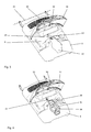
Figur 1 zeigt das Gehäuse 2 eines Bodenstaubsaugers 1. Es umfasst ein Unterteil 3, einen Abdeckrahmen 4, ein Oberteil 5, eine Kappe 6 und eine Rückwand 7. Abdeckrahmen 4 und Unterteil 3 formen im Gehäuseinneren einen Staubsammelraum 8, in den schmutzbeladene Luft eingeleitet und mit Hilfe eines nicht dargestellten Staubbeutels gefiltert wird. Das deckelartige Oberteil 5 ist schwenkbar gelagert und dient zum Verschluss des Staubsammelraums 8. Des Weiteren sind in dem Oberteil 5 Aufnahmen 9 (sieheFigur 2 ) für Saugzubehör (sieheFigur 5 ) angeordnet, welche durch einen Deckel 10 verschlossen werden können. - In der
Figur 2 ist das Oberteil 5 ohne Deckel 10 dargestellt. Von der Staubsammelraumseite her ist in das Oberteil 5 ein Funktionsmodul 11 eingesetzt, dessen Aufbau und Funktionen später detailliert erklärt sind. An dem Funktionsmodul 11 sind drei federnde Rasthaken 20, 21, 22 angeformt, die zur Halterung des Saugzubehörs dienen. Zur Erlangung der Federeigenschaften sind die Rasthaken 20 bis 22 wie das Modul 11 selbst aus Polypropylen (PP) hergestellt. Bei der Montage des Moduls 11 an dem Oberteil tauchen die Rasthaken 20 bis 22 durch eine gemeinsame Öffnung 23. Es zeigt dann je ein Rasthaken 20, 21, bzw. 22 auf eine der drei Aufnahmen 9. DieFiguren 3 und 4 verdeutlichen den Montagevorgang,Figur 3 zeigt die Öffnung 23, die nach oben durch einen Steg 24 verkleidet ist. Es ist außerdem erkennbar, wie die Rasthaken (hier 21), durch die inFigur 3 leere Öffnung 23 inFigur 4 hindurchtauchen. InFigur 5 ist das Oberteil mit dem durch die Rasthaken 20 bis 22 gehaltenen Saugzubehör, einer Fugendüse 25, einem Saugpinsel 26 und einer Polsterdüse 27 dargestellt. -
Figur 6 zeigt ein Funktionsmodul 11 als Einzelheit. Das Funktionsmodul 11 besitzt neben der Eigenschaft als Träger für die Rasthaken 20 bis 22 noch andere Aufgaben. In dem Modul 11 ist auf jeder Seite eine Öffnung 30 und 31 angeordnet, in die am Deckel befindliche Verschlusshaken 32 und 33 (sieheFiguren 3 bis 5 ) eintauchen können. Die Verschlusshaken werden dann durch eine federnde Verriegelung (nicht dargestellt) gehalten. Die Verriegelung kann durch Druck auf einen Entriegelungsknopf 34 gelöst werden. Oberhalb des Entriegelungsknopfes ist eine Filterwechselanzeige 35 vorhanden. Diese misst in bekannter Weise den im Staubsammelraum befindlichen Unterdruck und zeigt an, wenn dieser aufgrund der Verstopfung eines Filters steigt. Unter dem Entriegelungsknopf 34 befindet sich ein Anschlusstutzen 36 für einen nicht dargestellten Saugschlauch. Die designmäßig zusammengefasste Einheit aus Anschlussstutzen 36, Entriegelungsknopf 34 und Filterwechselanzeige 35 taucht bei der Montage des Funktionsmoduls 11 durch eine entsprechende Öffnung 37 im Oberteil 5, sieheFigur 3 . - In
Figur 7 ist ein weiteres Ausführungsbeispiel eines Funktionsmoduls 110 dargestellt. Dieses besitzt zusätzlich zu den Features der inFigur 6 dargestellten Variante eine Steckdose 111 zur Stromversorgung eines Saugzubehörs wie z. B. einer Elektrobodendüse mit rotierender Borstenwalze. Das Kabel 112 zur Steckdose wird in dem Modul 110 bis in den Schwenkachsenbereich 51 des Oberteils (sieheFigur 3 ) geführt und dort über eine Steckerverbindung 113 mit der nicht dargestellten Stromversorgung des Staubsaugers 1 verbunden. Des Weiteren ist in dem Funktionsmodul 110 eine Schlauchleitung 114 verlegt, die von einer Öffnung (in den Figuren nicht sichtbar) im Anschlusstutzen 36 bis in den Schwenkachsenbereich 51 des Oberteils 5 führt. Die Schlauchleitung 114 dient zur Ermittlung des Drucks im Bereich des Anschlussstutzens 36 mit Hilfe eines nicht dargestellten Drucksensors. Zur Halterung des Kabels 112 und/oder der Schlauchleitung 114 ist an das Funktionsmodul 110 ein Ausleger 115 angeformt.
Claims (12)
- Staubsauger (1), insbesondere Bodenstaubsauger, mit einem Gehäuse (2), welches ein deckelartiges Oberteil (5) zum Verschluss eines Staubsammelraums (8) und ein an der zum Staubsammelraum (8) gerichteten Innenseite angeordnetes Funktionsmodul (11, 110) umfasst, wobei an der Auβenseite des Oberteils (5) mindestens eine Aufnahme (9) für Saugzubehör (25, 26, 27) angeordnet ist, und wobei der Aufnahme (9) mindestens ein Rasthaken (20, 21, 22) zur Halterung des Saugzubehörs (25, 26, 27) zugeordnet ist, dadurch gekennzeichnet,
dass der Haken (20, 21, 22) an dem Funktionsmodul (11, 110) angeordnet ist und eine Öffnung (23) in dem Oberteil (5) durchtaucht. - Staubsauger (1) nach Anspruch 1,
dadurch gekennzeichnet,
dass in dem Oberteil (5) mehrere, vorzugsweise drei Aufnahmen (9) angeordnet sind, und dass jeder Aufnahme (9) mindestens ein Rasthaken (20, 21, 22) zugeordnet ist. - Staubsauger (1) nach Anspruch 2,
dadurch gekennzeichnet,
dass mehrere, vorzugsweise alle Rasthaken (20, 21, 22) durch eine gemeinsame Öffnung (23) im Oberteil (5) tauchen. - Staubsauger (1) nach mindestens einem der vorhergehenden Ansprüche,
dadurch gekennzeichnet,
dass die Rasthaken (20, 21, 22) an dem Funktionsmodul (11, 110) federnd gelagert sind. - Staubsauger (1) nach mindestens einem der vorhergehenden Ansprüche,
dadurch gekennzeichnet,
dass die Aufnahmen (9) durch einen am Oberteil (5) schwenkbar gelagerten Deckel (10) verschließbar sind. - Staubsauger (1) nach Anspruch 5,
dadurch gekennzeichnet,
dass an dem Funktionsmodul (11, 110) eine Verschlusseinrichtung für den Deckel (10) angeordnet ist. - Staubsauger (1) nach einem der vorhergehenden Ansprüche,
dadurch gekennzeichnet,
dass an dem Funktionsmodul (11, 110) ein Anschlussstutzen (36) für einen Saugschlauch angeordnet ist. - Staubsauger (1) nach einem der vorhergehenden Ansprüche,
dadurch gekennzeichnet,
dass an dem Funktionsmodul (11, 110) eine Filterwechselanzeige (35) angeordnet ist. - Staubsauger (1) nach einem der vorhergehenden Ansprüche,
dadurch gekennzeichnet,
dass an dem Funktionsmodul (110) eine Steckdose (111) zur Stromversorgung eines Saugzubehörs angeordnet ist. - Staubsauger (1) nach einem der vorhergehenden Ansprüche,
dadurch gekennzeichnet,
dass an dem Funktionsmodul (110) ein Kabel (112) zur Verbindung der Steckdose (111) mit der Stromversorgung des Staubsaugers (1) angeordnet ist. - Staubsauger (1) nach einem der vorhergehenden Ansprüche,
dadurch gekennzeichnet,
dass an dem Funktionsmodul (110) eine Schlauchleitung (114) zur Verbindung einer Luftöffnung mit einem Drucksensor angeordnet ist. - Staubsauger (1) nach mindestens einem der Ansprüche 10 oder 11,
dadurch gekennzeichnet,
dass an dem Funktionsmodul (110) ein Ausleger (115) zur Führung des Kabels (112) und/oder der Schlauchleitung (114) in einen Schwenkachsenbereich (51) des Oberteils (5) angeordnet ist.
Priority Applications (1)
| Application Number | Priority Date | Filing Date | Title |
|---|---|---|---|
| EP20100401117 EP2409626B1 (de) | 2010-07-20 | 2010-07-20 | Staubsauger, insbesondere einen Bodenstaubsauger, mit mindestens einer Aufnahme für Saugzubehör |
Applications Claiming Priority (1)
| Application Number | Priority Date | Filing Date | Title |
|---|---|---|---|
| EP20100401117 EP2409626B1 (de) | 2010-07-20 | 2010-07-20 | Staubsauger, insbesondere einen Bodenstaubsauger, mit mindestens einer Aufnahme für Saugzubehör |
Publications (2)
| Publication Number | Publication Date |
|---|---|
| EP2409626A1 true EP2409626A1 (de) | 2012-01-25 |
| EP2409626B1 EP2409626B1 (de) | 2014-04-16 |
Family
ID=43302243
Family Applications (1)
| Application Number | Title | Priority Date | Filing Date |
|---|---|---|---|
| EP20100401117 Active EP2409626B1 (de) | 2010-07-20 | 2010-07-20 | Staubsauger, insbesondere einen Bodenstaubsauger, mit mindestens einer Aufnahme für Saugzubehör |
Country Status (1)
| Country | Link |
|---|---|
| EP (1) | EP2409626B1 (de) |
Citations (3)
| Publication number | Priority date | Publication date | Assignee | Title |
|---|---|---|---|---|
| DE8423477U1 (de) | 1984-08-07 | 1985-12-05 | Bosch-Siemens Hausgeräte GmbH, 7000 Stuttgart | Staubsauger mit einem abnehmbaren Zubehörträger |
| DE3440910A1 (de) * | 1984-11-09 | 1986-05-15 | Licentia Patent-Verwaltungs-Gmbh, 6000 Frankfurt | Staubsauger mit einem klappbaren deckel fuer zubehoerteile |
| WO2006021503A1 (de) * | 2004-08-24 | 2006-03-02 | BSH Bosch und Siemens Hausgeräte GmbH | Staubsauger mit einer aufnahme für zubehörteile |
-
2010
- 2010-07-20 EP EP20100401117 patent/EP2409626B1/de active Active
Patent Citations (3)
| Publication number | Priority date | Publication date | Assignee | Title |
|---|---|---|---|---|
| DE8423477U1 (de) | 1984-08-07 | 1985-12-05 | Bosch-Siemens Hausgeräte GmbH, 7000 Stuttgart | Staubsauger mit einem abnehmbaren Zubehörträger |
| DE3440910A1 (de) * | 1984-11-09 | 1986-05-15 | Licentia Patent-Verwaltungs-Gmbh, 6000 Frankfurt | Staubsauger mit einem klappbaren deckel fuer zubehoerteile |
| WO2006021503A1 (de) * | 2004-08-24 | 2006-03-02 | BSH Bosch und Siemens Hausgeräte GmbH | Staubsauger mit einer aufnahme für zubehörteile |
Also Published As
| Publication number | Publication date |
|---|---|
| EP2409626B1 (de) | 2014-04-16 |
Similar Documents
| Publication | Publication Date | Title |
|---|---|---|
| DE112009002586B4 (de) | Handstaubsauger | |
| DE3417163C2 (de) | ||
| DE69920858T2 (de) | Kombination von Schmutzwassertank und Saugdüse für einen Staubsauger | |
| DE202017106417U1 (de) | Handextraktionsreiniger | |
| DE69622694T2 (de) | Elektrischer besen | |
| DE112009002152T5 (de) | Beutelankoppelanordnung für einen Staubsauger | |
| DE202016008976U1 (de) | Oberflächenreinigungsvorrichtung | |
| DE102010038095B4 (de) | Entleerungsstation für einen akkumulatorbetriebenen Elektrostaubsauger | |
| CN109068915A (zh) | 用于真空吸尘器的灰尘容器 | |
| EP2895045B1 (de) | Staubsauger | |
| US20130228194A1 (en) | Vacuum Filter System and Method with Integrated Filter Cleaning | |
| DE102011050181A1 (de) | Bodenwischgerät | |
| DE102014111248A1 (de) | Staubfilterbeutel für einen Staubsauger sowie Anordnung eines Staubfilterbeutels in einem Staubsauger | |
| WO2021233515A1 (de) | Rückentragbares batteriebetriebenes sauggerät | |
| DE102019128051B4 (de) | Saugreinigungsgerät mit einem eine Filterkammer verschließenden Kammerdeckel | |
| EP2409626B1 (de) | Staubsauger, insbesondere einen Bodenstaubsauger, mit mindestens einer Aufnahme für Saugzubehör | |
| DE3743083A1 (de) | Handstaubsauger | |
| DE102011054048A1 (de) | Bodenwischgerät | |
| DE102019121499A1 (de) | Wandhalterung für Staubsauger | |
| EP3772306A1 (de) | Wandhalterung für staubsauger, staubsauger und bodenpflegesystem | |
| DE102007040963A1 (de) | Staubsauger mit einem Motorgebläse, in dessen Ausblas-Luftstrom ein Feinfilter angeordnet ist | |
| EP3772305A1 (de) | Wandhalterung für staubsauger | |
| EP4154782B1 (de) | Staubsauger und staubbeutel | |
| CN111286932A (zh) | 用于衣物处理设备的衣物处理剂投放装置及衣物处理设备 | |
| DE102017208686A1 (de) | Reinigungsmittelkartusche, Reinigungsmitteldosiersystem und Haushalts-Geschirrspülmaschine |
Legal Events
| Date | Code | Title | Description |
|---|---|---|---|
| 17P | Request for examination filed |
Effective date: 20110107 |
|
| AK | Designated contracting states |
Kind code of ref document: A1 Designated state(s): AL AT BE BG CH CY CZ DE DK EE ES FI FR GB GR HR HU IE IS IT LI LT LU LV MC MK MT NL NO PL PT RO SE SI SK SM TR |
|
| AX | Request for extension of the european patent |
Extension state: BA ME RS |
|
| PUAI | Public reference made under article 153(3) epc to a published international application that has entered the european phase |
Free format text: ORIGINAL CODE: 0009012 |
|
| RIN1 | Information on inventor provided before grant (corrected) |
Inventor name: ROTH, MARTIN Inventor name: GERTH, VOLKER Inventor name: THAMM, MARKUS |
|
| RIC1 | Information provided on ipc code assigned before grant |
Ipc: A47L 9/00 20060101AFI20131106BHEP |
|
| GRAP | Despatch of communication of intention to grant a patent |
Free format text: ORIGINAL CODE: EPIDOSNIGR1 |
|
| INTG | Intention to grant announced |
Effective date: 20140103 |
|
| GRAS | Grant fee paid |
Free format text: ORIGINAL CODE: EPIDOSNIGR3 |
|
| GRAA | (expected) grant |
Free format text: ORIGINAL CODE: 0009210 |
|
| AK | Designated contracting states |
Kind code of ref document: B1 Designated state(s): AL AT BE BG CH CY CZ DE DK EE ES FI FR GB GR HR HU IE IS IT LI LT LU LV MC MK MT NL NO PL PT RO SE SI SK SM TR |
|
| REG | Reference to a national code |
Ref country code: GB Ref legal event code: FG4D Free format text: NOT ENGLISH |
|
| REG | Reference to a national code |
Ref country code: CH Ref legal event code: EP |
|
| REG | Reference to a national code |
Ref country code: DE Ref legal event code: R084 Ref document number: 502010006662 Country of ref document: DE |
|
| REG | Reference to a national code |
Ref country code: AT Ref legal event code: REF Ref document number: 662003 Country of ref document: AT Kind code of ref document: T Effective date: 20140515 |
|
| REG | Reference to a national code |
Ref country code: IE Ref legal event code: FG4D Free format text: LANGUAGE OF EP DOCUMENT: GERMAN |
|
| REG | Reference to a national code |
Ref country code: DE Ref legal event code: R096 Ref document number: 502010006662 Country of ref document: DE Effective date: 20140528 |
|
| REG | Reference to a national code |
Ref country code: GB Ref legal event code: 746 Effective date: 20140515 |
|
| REG | Reference to a national code |
Ref country code: DE Ref legal event code: R084 Ref document number: 502010006662 Country of ref document: DE Effective date: 20140514 |
|
| REG | Reference to a national code |
Ref country code: NL Ref legal event code: VDEP Effective date: 20140416 |
|
| REG | Reference to a national code |
Ref country code: LT Ref legal event code: MG4D |
|
| PG25 | Lapsed in a contracting state [announced via postgrant information from national office to epo] |
Ref country code: NL Free format text: LAPSE BECAUSE OF FAILURE TO SUBMIT A TRANSLATION OF THE DESCRIPTION OR TO PAY THE FEE WITHIN THE PRESCRIBED TIME-LIMIT Effective date: 20140416 Ref country code: FI Free format text: LAPSE BECAUSE OF FAILURE TO SUBMIT A TRANSLATION OF THE DESCRIPTION OR TO PAY THE FEE WITHIN THE PRESCRIBED TIME-LIMIT Effective date: 20140416 Ref country code: BG Free format text: LAPSE BECAUSE OF FAILURE TO SUBMIT A TRANSLATION OF THE DESCRIPTION OR TO PAY THE FEE WITHIN THE PRESCRIBED TIME-LIMIT Effective date: 20140716 Ref country code: LT Free format text: LAPSE BECAUSE OF FAILURE TO SUBMIT A TRANSLATION OF THE DESCRIPTION OR TO PAY THE FEE WITHIN THE PRESCRIBED TIME-LIMIT Effective date: 20140416 Ref country code: GR Free format text: LAPSE BECAUSE OF FAILURE TO SUBMIT A TRANSLATION OF THE DESCRIPTION OR TO PAY THE FEE WITHIN THE PRESCRIBED TIME-LIMIT Effective date: 20140717 Ref country code: IS Free format text: LAPSE BECAUSE OF FAILURE TO SUBMIT A TRANSLATION OF THE DESCRIPTION OR TO PAY THE FEE WITHIN THE PRESCRIBED TIME-LIMIT Effective date: 20140816 Ref country code: CY Free format text: LAPSE BECAUSE OF FAILURE TO SUBMIT A TRANSLATION OF THE DESCRIPTION OR TO PAY THE FEE WITHIN THE PRESCRIBED TIME-LIMIT Effective date: 20140416 Ref country code: NO Free format text: LAPSE BECAUSE OF FAILURE TO SUBMIT A TRANSLATION OF THE DESCRIPTION OR TO PAY THE FEE WITHIN THE PRESCRIBED TIME-LIMIT Effective date: 20140716 |
|
| PG25 | Lapsed in a contracting state [announced via postgrant information from national office to epo] |
Ref country code: SE Free format text: LAPSE BECAUSE OF FAILURE TO SUBMIT A TRANSLATION OF THE DESCRIPTION OR TO PAY THE FEE WITHIN THE PRESCRIBED TIME-LIMIT Effective date: 20140416 Ref country code: LV Free format text: LAPSE BECAUSE OF FAILURE TO SUBMIT A TRANSLATION OF THE DESCRIPTION OR TO PAY THE FEE WITHIN THE PRESCRIBED TIME-LIMIT Effective date: 20140416 Ref country code: PL Free format text: LAPSE BECAUSE OF FAILURE TO SUBMIT A TRANSLATION OF THE DESCRIPTION OR TO PAY THE FEE WITHIN THE PRESCRIBED TIME-LIMIT Effective date: 20140416 Ref country code: HR Free format text: LAPSE BECAUSE OF FAILURE TO SUBMIT A TRANSLATION OF THE DESCRIPTION OR TO PAY THE FEE WITHIN THE PRESCRIBED TIME-LIMIT Effective date: 20140416 Ref country code: ES Free format text: LAPSE BECAUSE OF FAILURE TO SUBMIT A TRANSLATION OF THE DESCRIPTION OR TO PAY THE FEE WITHIN THE PRESCRIBED TIME-LIMIT Effective date: 20140416 |
|
| PG25 | Lapsed in a contracting state [announced via postgrant information from national office to epo] |
Ref country code: PT Free format text: LAPSE BECAUSE OF FAILURE TO SUBMIT A TRANSLATION OF THE DESCRIPTION OR TO PAY THE FEE WITHIN THE PRESCRIBED TIME-LIMIT Effective date: 20140818 |
|
| REG | Reference to a national code |
Ref country code: DE Ref legal event code: R097 Ref document number: 502010006662 Country of ref document: DE |
|
| PG25 | Lapsed in a contracting state [announced via postgrant information from national office to epo] |
Ref country code: EE Free format text: LAPSE BECAUSE OF FAILURE TO SUBMIT A TRANSLATION OF THE DESCRIPTION OR TO PAY THE FEE WITHIN THE PRESCRIBED TIME-LIMIT Effective date: 20140416 Ref country code: DK Free format text: LAPSE BECAUSE OF FAILURE TO SUBMIT A TRANSLATION OF THE DESCRIPTION OR TO PAY THE FEE WITHIN THE PRESCRIBED TIME-LIMIT Effective date: 20140416 Ref country code: RO Free format text: LAPSE BECAUSE OF FAILURE TO SUBMIT A TRANSLATION OF THE DESCRIPTION OR TO PAY THE FEE WITHIN THE PRESCRIBED TIME-LIMIT Effective date: 20140416 Ref country code: CZ Free format text: LAPSE BECAUSE OF FAILURE TO SUBMIT A TRANSLATION OF THE DESCRIPTION OR TO PAY THE FEE WITHIN THE PRESCRIBED TIME-LIMIT Effective date: 20140416 Ref country code: SK Free format text: LAPSE BECAUSE OF FAILURE TO SUBMIT A TRANSLATION OF THE DESCRIPTION OR TO PAY THE FEE WITHIN THE PRESCRIBED TIME-LIMIT Effective date: 20140416 |
|
| PLBE | No opposition filed within time limit |
Free format text: ORIGINAL CODE: 0009261 |
|
| STAA | Information on the status of an ep patent application or granted ep patent |
Free format text: STATUS: NO OPPOSITION FILED WITHIN TIME LIMIT |
|
| PG25 | Lapsed in a contracting state [announced via postgrant information from national office to epo] |
Ref country code: LU Free format text: LAPSE BECAUSE OF FAILURE TO SUBMIT A TRANSLATION OF THE DESCRIPTION OR TO PAY THE FEE WITHIN THE PRESCRIBED TIME-LIMIT Effective date: 20140720 |
|
| REG | Reference to a national code |
Ref country code: CH Ref legal event code: PL |
|
| 26N | No opposition filed |
Effective date: 20150119 |
|
| REG | Reference to a national code |
Ref country code: IE Ref legal event code: MM4A |
|
| PG25 | Lapsed in a contracting state [announced via postgrant information from national office to epo] |
Ref country code: CH Free format text: LAPSE BECAUSE OF NON-PAYMENT OF DUE FEES Effective date: 20140731 Ref country code: LI Free format text: LAPSE BECAUSE OF NON-PAYMENT OF DUE FEES Effective date: 20140731 |
|
| REG | Reference to a national code |
Ref country code: DE Ref legal event code: R097 Ref document number: 502010006662 Country of ref document: DE Effective date: 20150119 |
|
| PG25 | Lapsed in a contracting state [announced via postgrant information from national office to epo] |
Ref country code: SI Free format text: LAPSE BECAUSE OF FAILURE TO SUBMIT A TRANSLATION OF THE DESCRIPTION OR TO PAY THE FEE WITHIN THE PRESCRIBED TIME-LIMIT Effective date: 20140416 |
|
| PG25 | Lapsed in a contracting state [announced via postgrant information from national office to epo] |
Ref country code: IE Free format text: LAPSE BECAUSE OF NON-PAYMENT OF DUE FEES Effective date: 20140720 |
|
| PGFP | Annual fee paid to national office [announced via postgrant information from national office to epo] |
Ref country code: IT Payment date: 20150728 Year of fee payment: 6 |
|
| PG25 | Lapsed in a contracting state [announced via postgrant information from national office to epo] |
Ref country code: SM Free format text: LAPSE BECAUSE OF FAILURE TO SUBMIT A TRANSLATION OF THE DESCRIPTION OR TO PAY THE FEE WITHIN THE PRESCRIBED TIME-LIMIT Effective date: 20140416 Ref country code: MC Free format text: LAPSE BECAUSE OF FAILURE TO SUBMIT A TRANSLATION OF THE DESCRIPTION OR TO PAY THE FEE WITHIN THE PRESCRIBED TIME-LIMIT Effective date: 20140416 |
|
| PG25 | Lapsed in a contracting state [announced via postgrant information from national office to epo] |
Ref country code: MT Free format text: LAPSE BECAUSE OF FAILURE TO SUBMIT A TRANSLATION OF THE DESCRIPTION OR TO PAY THE FEE WITHIN THE PRESCRIBED TIME-LIMIT Effective date: 20140416 |
|
| REG | Reference to a national code |
Ref country code: FR Ref legal event code: PLFP Year of fee payment: 7 |
|
| PG25 | Lapsed in a contracting state [announced via postgrant information from national office to epo] |
Ref country code: BE Free format text: LAPSE BECAUSE OF FAILURE TO SUBMIT A TRANSLATION OF THE DESCRIPTION OR TO PAY THE FEE WITHIN THE PRESCRIBED TIME-LIMIT Effective date: 20140731 Ref country code: HU Free format text: LAPSE BECAUSE OF FAILURE TO SUBMIT A TRANSLATION OF THE DESCRIPTION OR TO PAY THE FEE WITHIN THE PRESCRIBED TIME-LIMIT; INVALID AB INITIO Effective date: 20100720 Ref country code: IT Free format text: LAPSE BECAUSE OF NON-PAYMENT OF DUE FEES Effective date: 20150720 Ref country code: TR Free format text: LAPSE BECAUSE OF FAILURE TO SUBMIT A TRANSLATION OF THE DESCRIPTION OR TO PAY THE FEE WITHIN THE PRESCRIBED TIME-LIMIT Effective date: 20140416 |
|
| REG | Reference to a national code |
Ref country code: AT Ref legal event code: MM01 Ref document number: 662003 Country of ref document: AT Kind code of ref document: T Effective date: 20150720 |
|
| PG25 | Lapsed in a contracting state [announced via postgrant information from national office to epo] |
Ref country code: AT Free format text: LAPSE BECAUSE OF NON-PAYMENT OF DUE FEES Effective date: 20150720 |
|
| REG | Reference to a national code |
Ref country code: FR Ref legal event code: PLFP Year of fee payment: 8 |
|
| PG25 | Lapsed in a contracting state [announced via postgrant information from national office to epo] |
Ref country code: MK Free format text: LAPSE BECAUSE OF FAILURE TO SUBMIT A TRANSLATION OF THE DESCRIPTION OR TO PAY THE FEE WITHIN THE PRESCRIBED TIME-LIMIT Effective date: 20140416 |
|
| REG | Reference to a national code |
Ref country code: FR Ref legal event code: PLFP Year of fee payment: 9 |
|
| PG25 | Lapsed in a contracting state [announced via postgrant information from national office to epo] |
Ref country code: AL Free format text: LAPSE BECAUSE OF FAILURE TO SUBMIT A TRANSLATION OF THE DESCRIPTION OR TO PAY THE FEE WITHIN THE PRESCRIBED TIME-LIMIT Effective date: 20140416 |
|
| P01 | Opt-out of the competence of the unified patent court (upc) registered |
Effective date: 20230529 |
|
| PGFP | Annual fee paid to national office [announced via postgrant information from national office to epo] |
Ref country code: DE Payment date: 20250731 Year of fee payment: 16 |
|
| PGFP | Annual fee paid to national office [announced via postgrant information from national office to epo] |
Ref country code: GB Payment date: 20250722 Year of fee payment: 16 |
|
| PGFP | Annual fee paid to national office [announced via postgrant information from national office to epo] |
Ref country code: FR Payment date: 20250725 Year of fee payment: 16 |